
Design Scalability Study of the Γ-Shaped Piezoelectric Harvester Based on Generalized Classical Ritz Method and Optimization


Abstract
:1. Introduction
- Development of a GCRM-P model to predict linear electromechanical behaviors of PE harvesters having multiple structural members,
- Experimental validation for the GCRM-P model in terms of energy harvesting performance,
- Study of design scalability—design optimization of EH under different mass scales, and comparison of the power output performance with the other recent PE harvester studies.
2. Generalized CRM for Piezoelectric Harvester (GCRM-P)
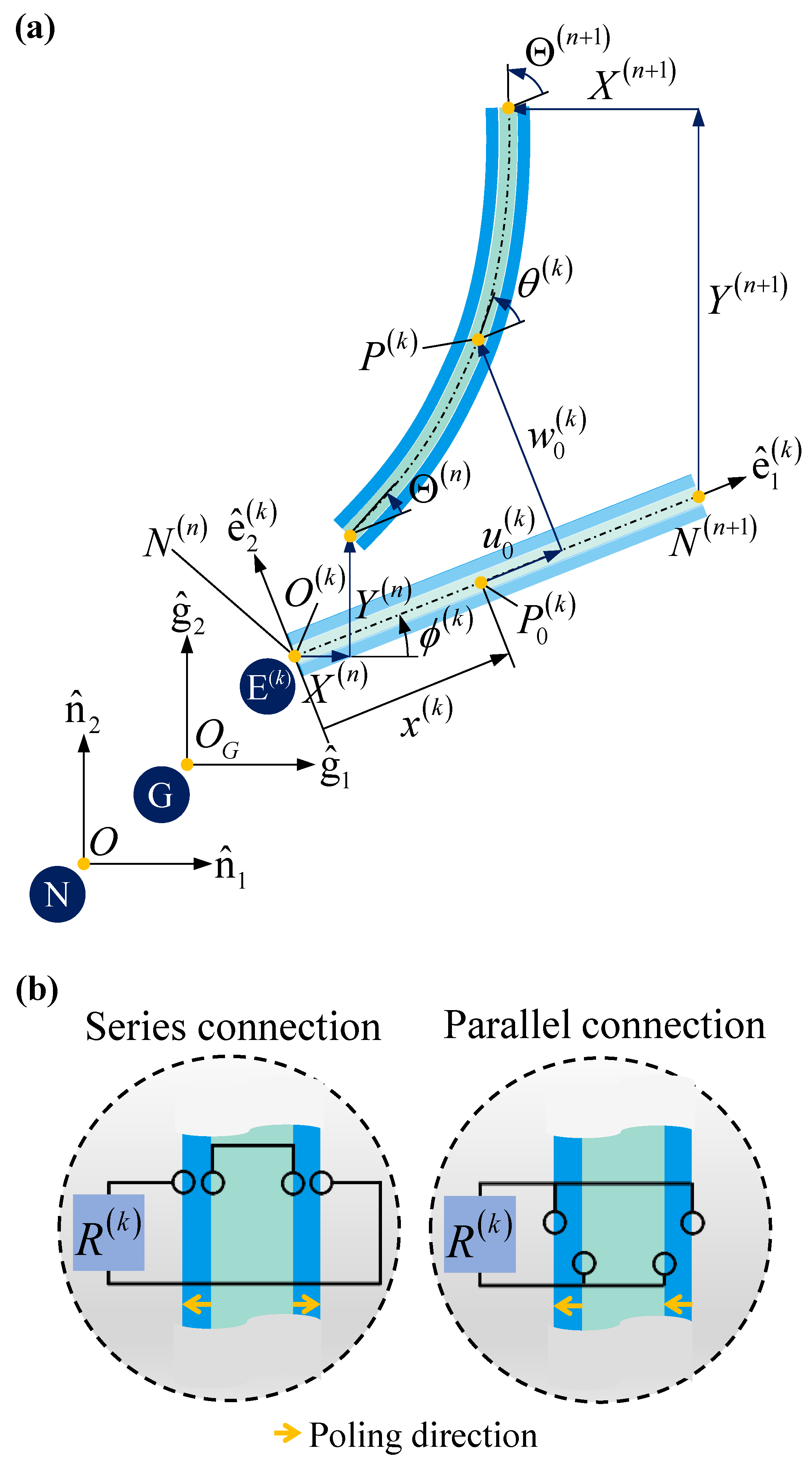
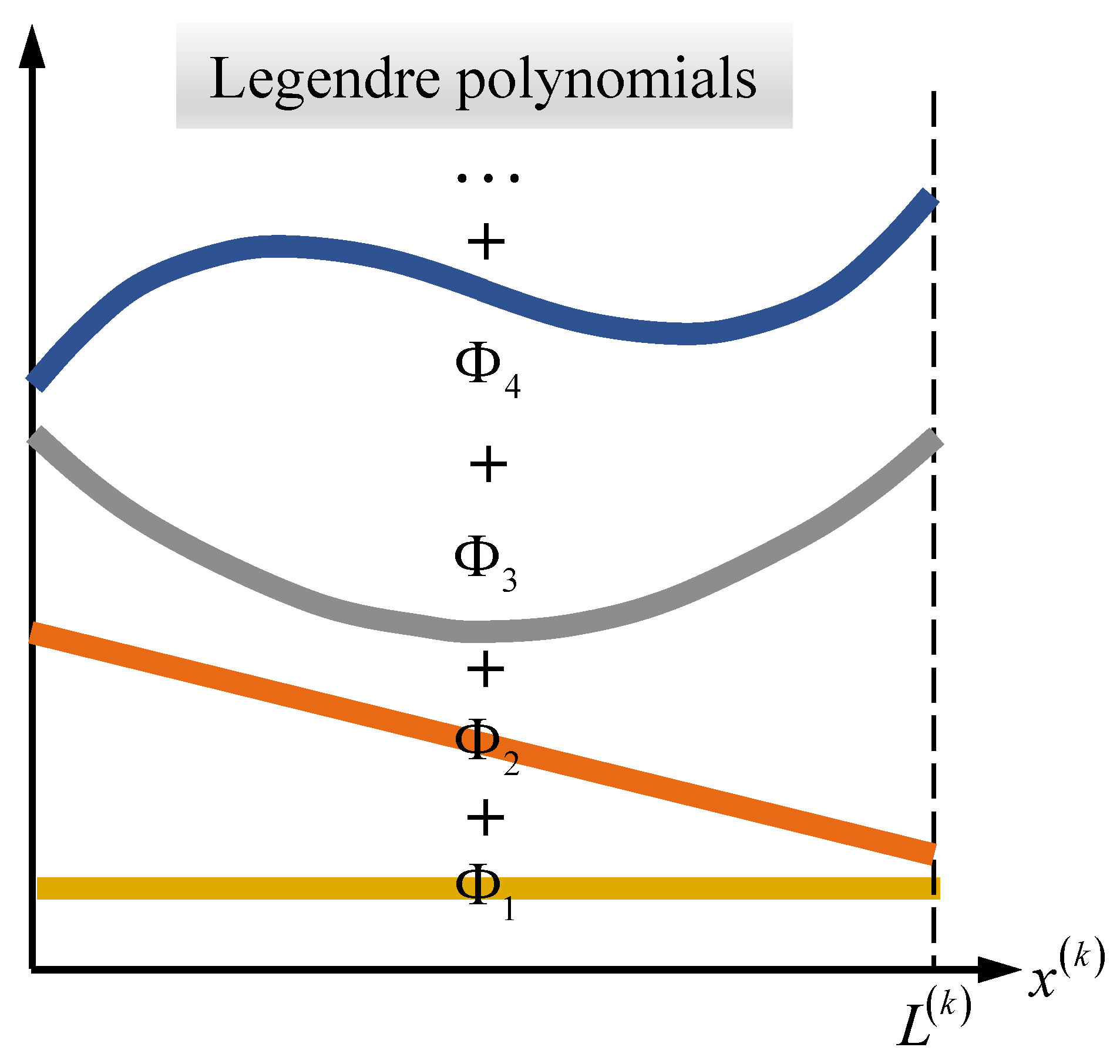
2.1. Description for a Unit Element
2.2. Electromechanical Energy Formulations
2.3. Constraint Equations
2.4. Spatial Discretization and Electromechanical Equations of Motion
3. System Descriptions for the EH
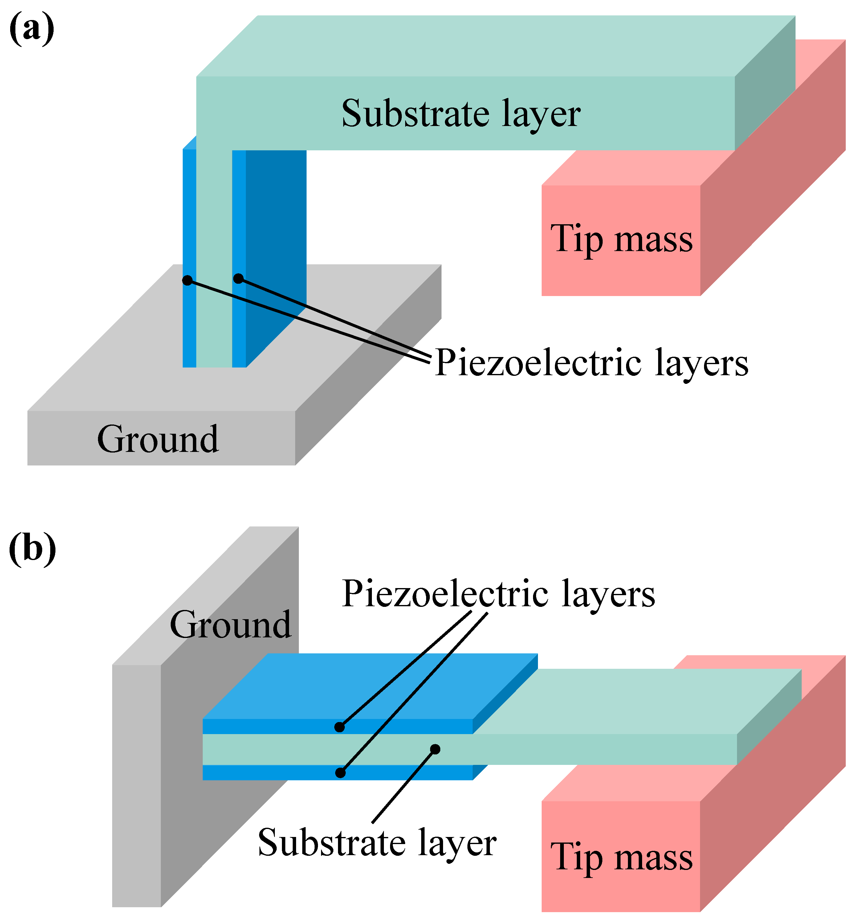
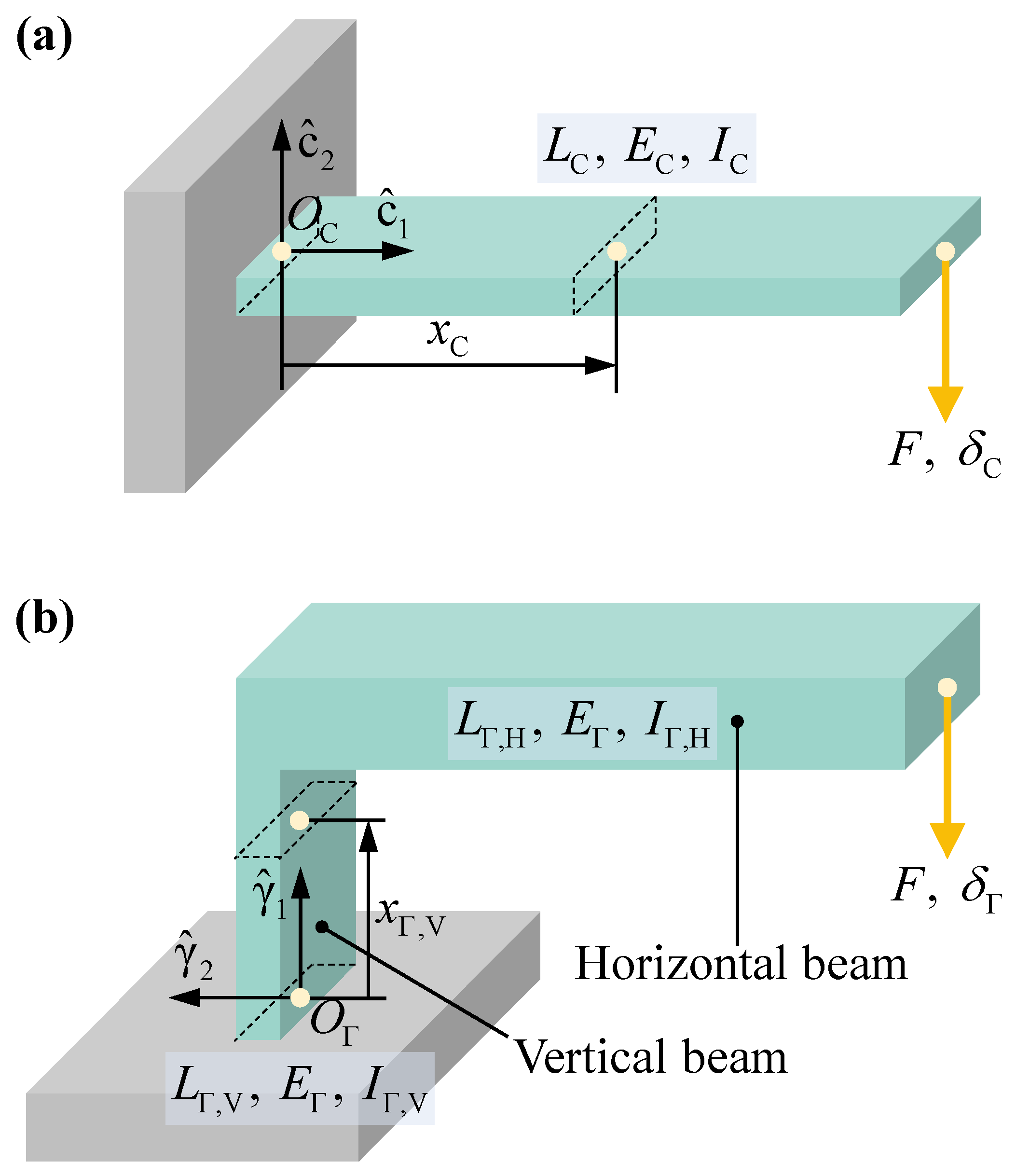
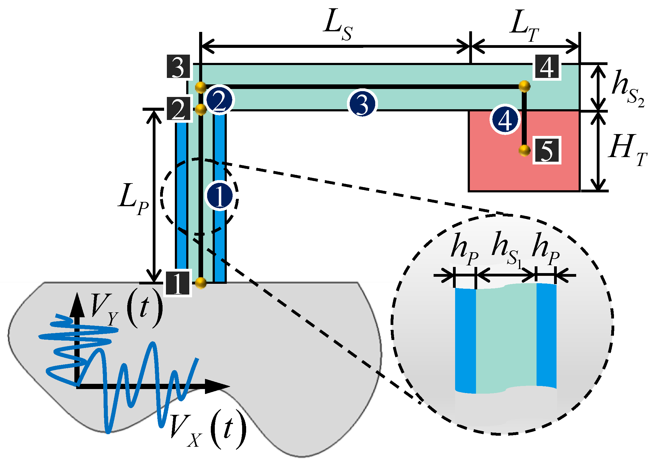
3.1. Uniform Strain Distribution in -Shaped Structure
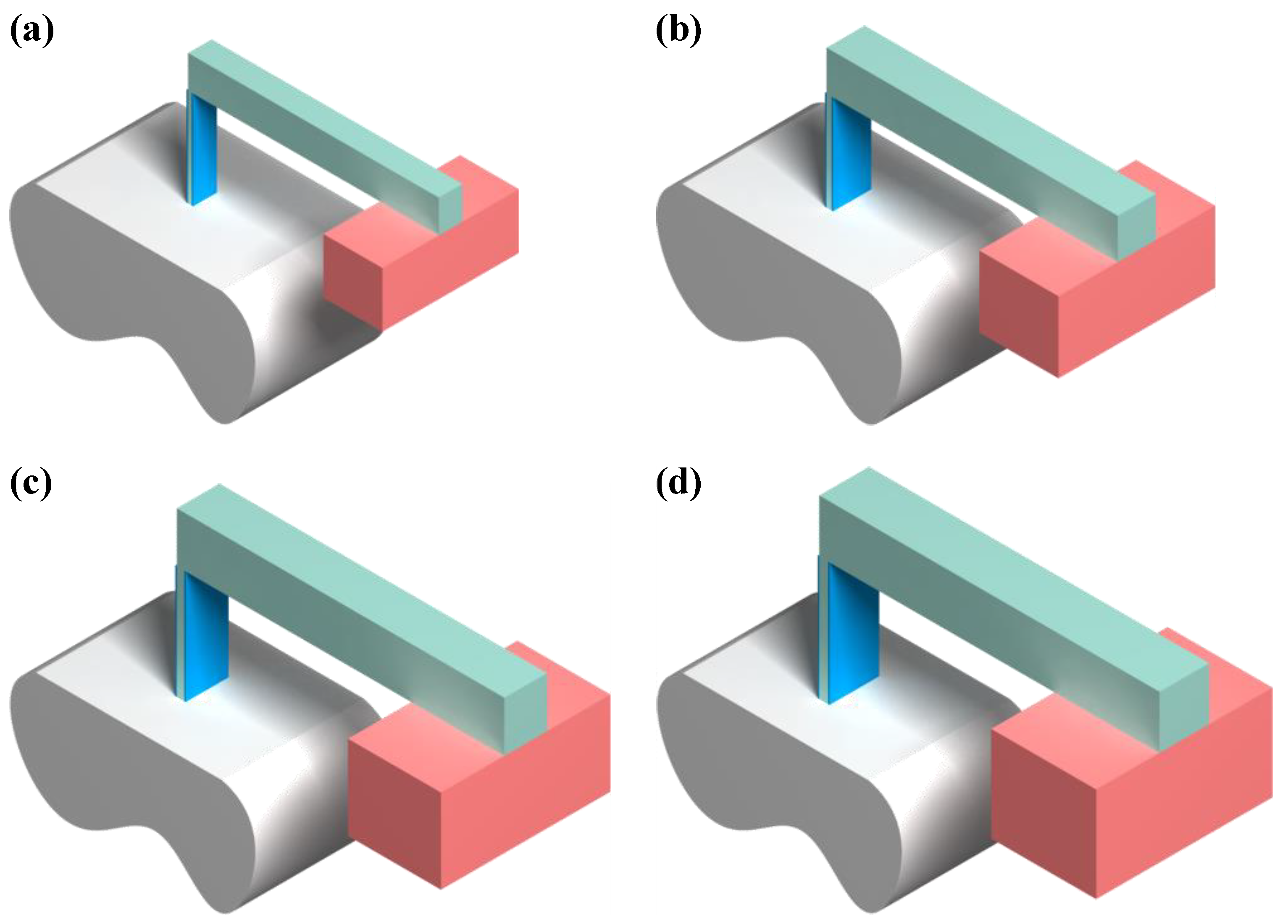
3.2. Configuration of -Shaped Harvester
4. Shape Optimization
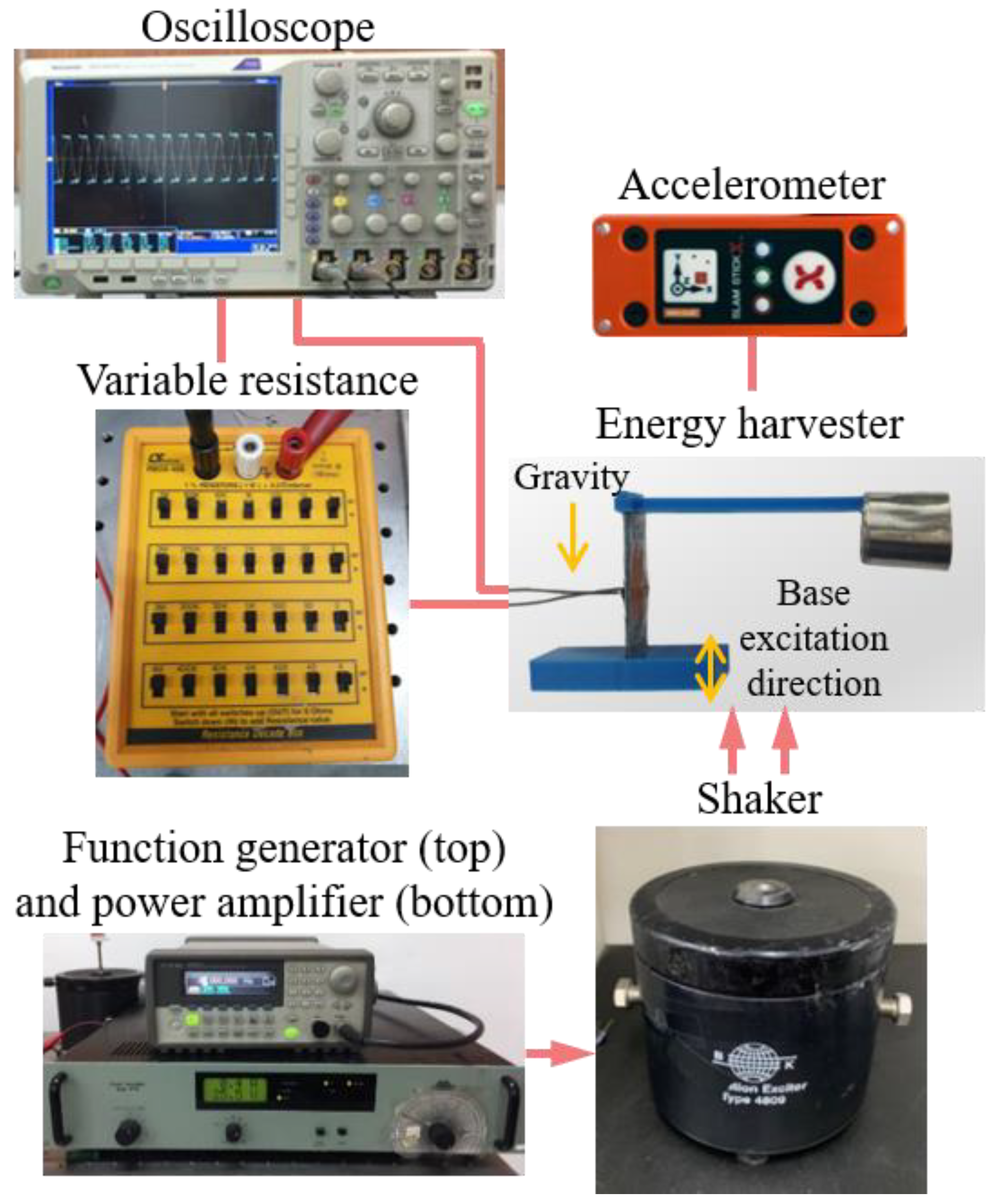
4.1. Experimental Validation of the GCRM-P Model for EH
4.2. Design Formulation
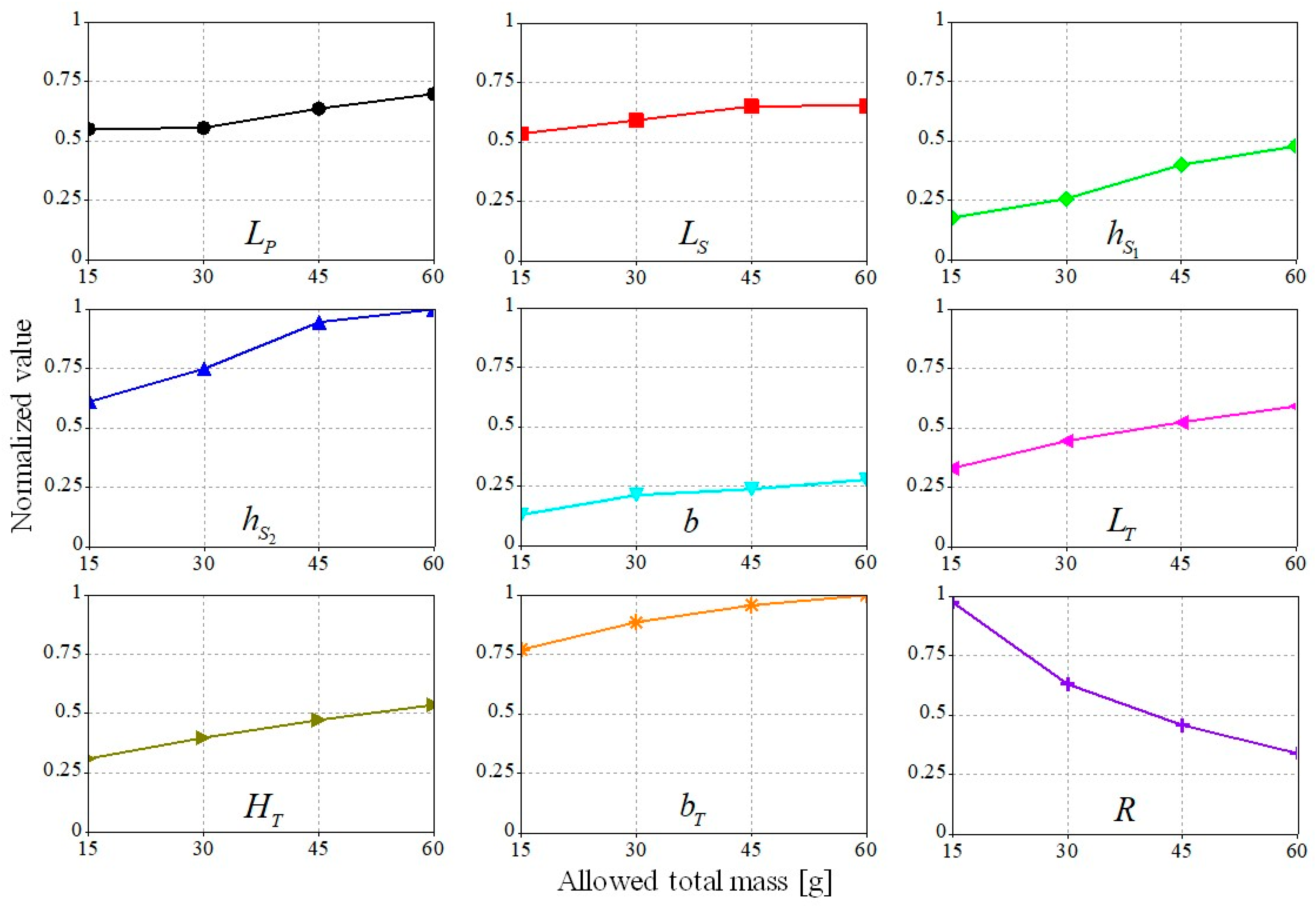
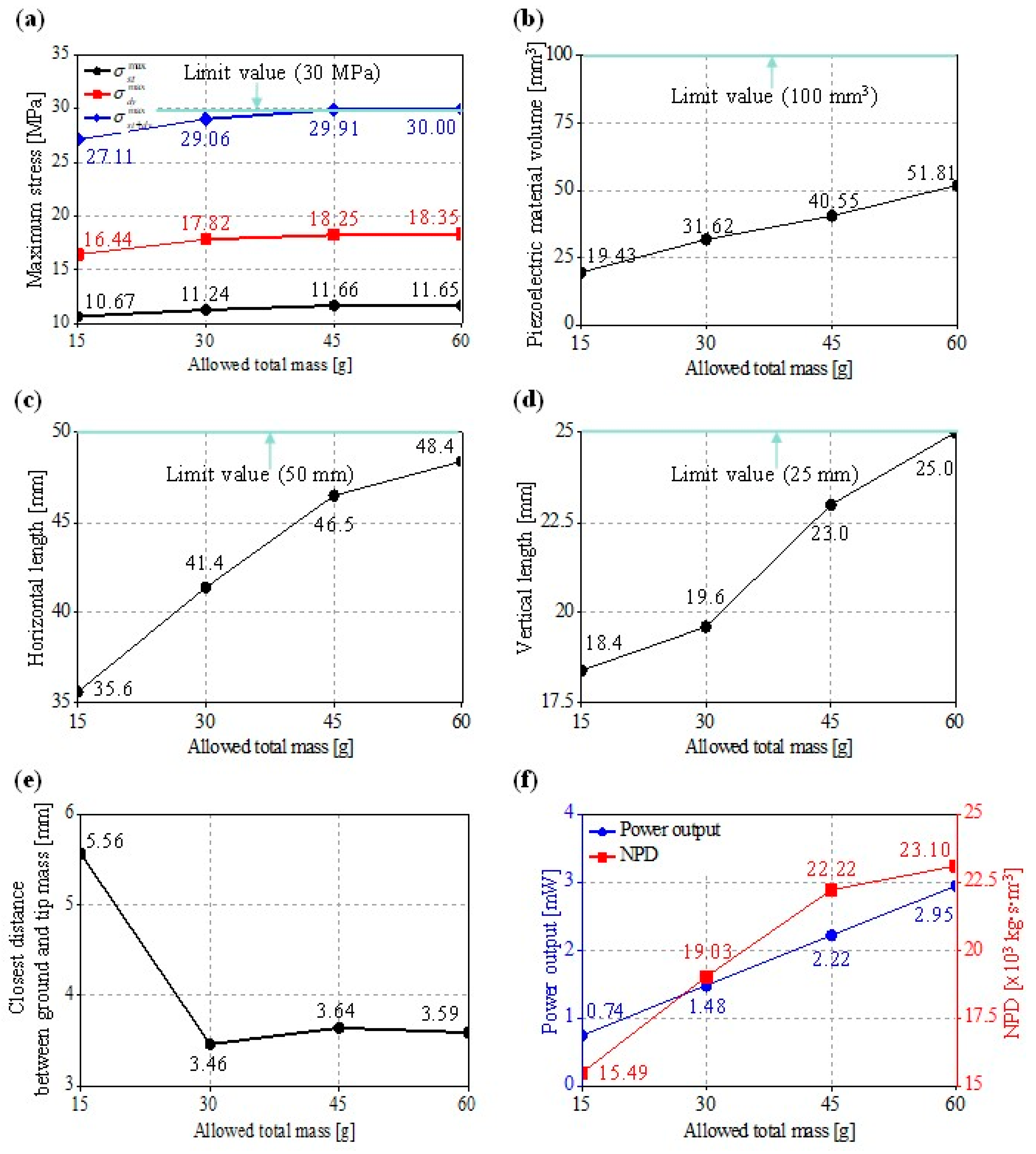
4.3. Shape Optimization Results and Discussions
5. Conclusions
- (1)
- The accuracy of the proposed GCRM-P model used for the frequency response analysis of the EH was experimentally validated with the error 5.5% for the peak power frequency.
- (2)
- The proposed DE-based approach successfully provided the optimized solutions with the high NPDs, while satisfying the six design constraints. Specifically, we could obtain higher harvester NPDs than the multiple mesoscale PE harvesters from recent studies.
- (3)
- The linear relation between the harvester mass (Mallowed) and power performance does not necessarily mean that all the design variables are linearly scaled—they need to be carefully chosen to maximize the power output while satisfying all of the constraints, especially the stress and the natural frequency measures.
Author Contributions
Funding
Data Availability Statement
Acknowledgments
Conflicts of Interest
References
- Erturk, A.; Inman, D.J. Piezoelectric Energy Harvesting; John Wiley & Sons Ltd: Hoboken, NJ, USA, 2011. [Google Scholar]
- Cook-Chennault, K.A.; Thambi, N.; Sastry, A.M. Powering MEMS portable devices—a review of non-regenerative and re-generative power supply systems with special emphasis on piezoelectric energy harvesting systems. Smart Mater. Struct. 2008, 17, 043001. [Google Scholar] [CrossRef] [Green Version]
- Jeon, Y.; Sood, R.; Jeong, J.-H.; Kim, S.-G. MEMS power generator with transverse mode thin film PZT. Sens. Actuators A Phys. 2005, 122, 16–22. [Google Scholar] [CrossRef]
- Yang, Z.; Zhou, S.; Zu, J.; Inman, D. High-performance piezoelectric energy harvesters and their applications. Joule 2018, 2, 642–697. [Google Scholar] [CrossRef] [Green Version]
- Safaei, M.; Sodano, H.A.; Anton, S.R. A review of energy harvesting using piezoelectric materials: State-of-the-art a decade later (2008–2018). Smart Mater. Struct. 2019, 28, 113001. [Google Scholar] [CrossRef]
- Lee, S.; Youn, B.D.; Jung, B.C. Robust segment-type energy harvester and its application to a wireless sensor. Smart Mater. Struct. 2009, 18, 095021. [Google Scholar] [CrossRef]
- Lee, S.; Youn, B.D. A design and experimental verification methodology for an energy harvester skin structure. Smart Mater. Struct. 2011, 20, 057001. [Google Scholar] [CrossRef]
- Miller, L.M.; Halvorsen, E.; Dong, T.; Wright, P.K. Modeling and experimental verification of low-frequency MEMS energy harvesting from ambient vibrations. J. Micromech. Microeng. 2011, 21, 045029. [Google Scholar] [CrossRef]
- Izadgoshasb, I.; Lim, Y.Y.; Lake, N.; Tang, L.; Padilla, R.V.; Kashiwao, T. Optimizing orientation of piezoelectric cantilever beam for harvesting energy from human walking. Energy Convers. Manag. 2018, 161, 66–73. [Google Scholar] [CrossRef]
- Izadgoshasb, I.; Lim, Y.Y.; Tang, L.; Padilla, R.V.; Tang, Z.S.; Sedighi, M. Improving efficiency of piezoelectric based energy harvesting from human motions using double pendulum system. Energy Convers. Manag. 2019, 184, 559–570. [Google Scholar] [CrossRef]
- Turkmen, A.C.; Celik, C. Energy harvesting with the piezoelectric material integrated shoe. Energy 2018, 150, 556–564. [Google Scholar] [CrossRef]
- Qian, F.; Xu, T.-B.; Zuo, L. Piezoelectric energy harvesting from human walking using a two-stage amplification mechanism. Energy 2019, 189, 116140. [Google Scholar] [CrossRef]
- Jeong, S.Y.; Hwang, W.S.; Cho, J.Y.; Jeong, J.C.; Ahn, J.H.; Kim, K.B.; Hong, S.D.; Song, G.J.; Jeon, D.H.; Sung, T.H. Piezoelectric device operating as sensor and harvester to drive switching circuit in LED shoes. Energy 2019, 177, 87–93. [Google Scholar] [CrossRef]
- Song, G.J.; Cho, J.Y.; Kim, K.-B.; Ahn, J.H.; Song, Y.; Hwang, W.; Hong, S.D.; Sung, T.H. Development of a pavement block piezoelectric energy harvester for self-powered walkway applications. Appl. Energy 2019, 256, 113916. [Google Scholar] [CrossRef]
- Cho, J.Y.; Kim, K.-B.; Hwang, W.S.; Yang, C.H.; Ahn, J.H.; Hong, S.D.; Jeon, D.H.; Song, G.J.; Ryu, C.H.; Woo, S.B.; et al. A multifunctional road-compatible piezoelectric energy harvester for autonomous driver-assist LED indicators with a self-monitoring system. Appl. Energy 2019, 242, 294–301. [Google Scholar] [CrossRef]
- Hwang, W.; Kim, K.B.; Cho, J.Y.; Yang, C.H.; Kim, J.H.; Song, G.J.; Kim, J. Watts-level road-compatible piezo-electric energy harvester for a self-powered temperature monitoring system on an actual roadway. Appl. Energy 2019, 243, 313–320. [Google Scholar] [CrossRef]
- Wang, S.; Wang, C.; Yu, G.; Gao, Z. Development and performance of a piezoelectric energy conversion structure applied in pavement. Energy Convers. Manag. 2020, 207, 112571. [Google Scholar] [CrossRef]
- Peigney, M.; Siegert, D. Piezoelectric energy harvesting from traffic-induced bridge vibrations. Smart Mater. Struct. 2013, 22, 095019. [Google Scholar] [CrossRef] [Green Version]
- Usman, M.; Hanif, A.; Kim, I.-H.; Jung, H.-J. Experimental validation of a novel piezoelectric energy harvesting system employing wake galloping phenomenon for a broad wind spectrum. Energy 2018, 153, 882–889. [Google Scholar] [CrossRef]
- Bolat, F.C.; Basaran, S.; Sivrioglu, S. Piezoelectric and electromagnetic hybrid energy harvesting with low-frequency vibrations of an aerodynamic profile under the air effect. Mech. Syst. Signal Process. 2019, 133, 106246. [Google Scholar] [CrossRef]
- Jia, J.; Shan, X.; Upadrashta, D.; Xie, T.; Yang, Y.; Song, R. An asymmetric bending-torsional piezoelectric energy harvester at low wind speed. Energy 2020, 198, 117287. [Google Scholar] [CrossRef]
- Bao, B.; Chen, W.; Wang, Q. A piezoelectric hydro-energy harvester featuring a special container structure. Energy 2019, 189, 116261. [Google Scholar] [CrossRef]
- Wong, V.-K.; Ho, J.-H.; Chai, A.-B. Performance of a piezoelectric energy harvester in actual rain. Energy 2017, 124, 364–371. [Google Scholar] [CrossRef]
- Lee, J.; Choi, B. Development of a piezoelectric energy harvesting system for implementing wireless sensors on the tires. Energy Convers. Manag. 2014, 78, 32–38. [Google Scholar] [CrossRef]
- Eshghi, A.T.; Lee, S.; Sadoughi, M.K.; Hu, C.; Kim, Y.-C.; Seo, J.-H. Design optimization under uncertainty and speed variability for a piezoelectric energy harvester powering a tire pressure monitoring sensor. Smart Mater. Struct. 2017, 26, 105037. [Google Scholar] [CrossRef]
- Dagdeviren, C.; Yang, B.D.; Su, Y.; Tran, P.L.; Joe, P.; Anderson, E.; Xia, J.; Doraiswamy, V.; Dehdashti, B.; Feng, X.; et al. Conformal piezoelectric energy harvesting and storage from motions of the heart, lung, and diaphragm. Proc. Natl. Acad. Sci. USA 2014, 111, 1927–1932. [Google Scholar] [CrossRef] [PubMed] [Green Version]
- Zhang, H.; Zhang, X.-S.; Cheng, X.; Liu, Y.; Han, M.; Xue, X.; Wang, S.; Yang, F.; Smitha, A.S.; Zhang, H.; et al. A flexible and implantable piezoelectric generator harvesting energy from the pulsation of ascending aorta: In vitro and in vivo studies. Nano Energy 2015, 12, 296–304. [Google Scholar] [CrossRef]
- Lü, C.; Zhang, Y.; Zhang, H.; Zhang, Z.; Shen, M.; Chen, Y. Generalized optimization method for energy conversion and storage efficiency of nanoscale flexible piezoelectric energy harvesters. Energy Convers. Manag. 2019, 182, 34–40. [Google Scholar] [CrossRef]
- Khazaee, M.; Rosendahl, L.; Rezania, A. A comprehensive electromechanically coupled model for non-uniform piezoelectric energy harvesting composite laminates. Mech. Syst. Signal Process. 2020, 145, 106927. [Google Scholar] [CrossRef]
- Hwang, W.-S.; Park, H.C. Finite element modeling of piezoelectric sensors and actuators. AIAA J. 1993, 31, 930–937. [Google Scholar] [CrossRef]
- Erturk, A.; Inman, D.J. An experimentally validated bimorph cantilever model for piezoelectric energy harvesting from base excitations. Smart Mater. Struct. 2009, 18, 025009. [Google Scholar] [CrossRef]
- Erturk, A.; Renno, J.; Inman, D.J. Modeling of Piezoelectric Energy Harvesting from an L-shaped Beam-mass Structure with an Application to UAVs. J. Intell. Mater. Syst. Struct. 2008, 20, 529–544. [Google Scholar] [CrossRef]
- Li, H.; Liu, D.; Wang, J.; Shang, X.; Hajj, M.R. Broadband bimorph piezoelectric energy harvesting by exploiting bending-torsion of L-shaped structure. Energy Convers. Manag. 2020, 206, 112503. [Google Scholar] [CrossRef]
- Anton, S.R.; Erturk, A.; Inman, D.J. Multifunctional self-charging structures using piezoceramics and thin-film batteries. Smart Mater. Struct. 2010, 19, 115021. [Google Scholar] [CrossRef]
- Erturk, A.; Inman, D.J. Assumed-modes formulation of piezoelectric energy harvesters: Euler-bernoulli, rayleigh and timoshenko models with axial deformations. In Proceedings of the ASME 2010 10th Biennial Conference on Engineering Systems Design and Analysis, Istanbul, Turkey, 12–14 July 2010; Volume 3, pp. 405–414. [Google Scholar] [CrossRef]
- Jeong, S.-W.; Cho, J.Y.; Sung, T.H.; Yoo, H.H. Electromechanical modeling and power performance analysis of a piezoelectric energy harvester having an attached mass and a segmented piezoelectric layer. Smart Mater. Struct. 2016, 26, 035035. [Google Scholar] [CrossRef]
- Jung, H.J.; Lee, S.; Jeong, S.-W.; Yoo, H.H. Segmented impact-type piezoelectric energy harvester for self-start impedance matching circuit. Smart Mater. Struct. 2018, 27, 114006. [Google Scholar] [CrossRef]
- Morales, C. Dynamic analysis of frames by a Rayleigh–Ritz based substructure synthesis method. Eng. Struct. 2000, 22, 1632–1640. [Google Scholar] [CrossRef]
- Meirovitch, L.; Kwak, M.K. Convergence of the classical Rayleigh-Ritz method and the finite element method. AIAA J. 1990, 28, 1509–1516. [Google Scholar] [CrossRef]
- Jeong, S.; Yoo, H.H. Flexibility modeling of a beam undergoing large deflection using the assumed mode meth-od. Int. J. Mech. Sci. 2017, 133, 611–618. [Google Scholar] [CrossRef]
- Jeong, S.; Yoo, H.H. Nonlinear structural analysis of a flexible multibody system using the classical Rayleigh–Ritz method. Int. J. Non-Linear Mech. 2019, 110, 69–80. [Google Scholar] [CrossRef]
- Jeong, S.; Yoo, H.H. Generalized classical Ritz method for modeling geometrically nonlinear flexible multibody systems having a general topology. Int. J. Mech. Sci. 2020, 181, 105687. [Google Scholar] [CrossRef]
- Leadenham, S.; Erturk, A. M-shaped asymmetric nonlinear oscillator for broadband vibration energy harvesting: Harmonic balance analysis and experimental validation. J. Sound Vib. 2014, 333, 6209–6223. [Google Scholar] [CrossRef]
- Leadenham, S.; Erturk, A. Nonlinear M-shaped broadband piezoelectric energy harvester for very low base accel-erations: Primary and secondary resonances. Smart Mater. Struct. 2015, 24, 055021. [Google Scholar] [CrossRef] [Green Version]
- Essink, B.C.; Hobeck, J.D.; Owen, R.B.; Inman, D.J. Magnetoelastic energy harvester for structural health monitoring applications. In Active and Passive Smart Structures and Integrated Systems; SPIE: Bellingham, WA, USA, 2015; Volume 9431, p. 943123. [Google Scholar]
- Hobeck, J.D.; Inman, D.J., Sr. Simultaneous passive broadband vibration suppression and energy harvesting with multifunctional metastructures. In A Tribute Conference Honoring Daniel Inman; SPIE: Bellington, WA, USA, 2017; Volume 10172, p. 101720K. [Google Scholar]
- Zhou, S.; Chen, W.; Malakooti, M.H.; Cao, J.; Inman, D.J. Design and modeling of a flexible longitudinal zigzag structure for enhanced vibration energy harvesting. J. Intell. Mater. Syst. Struct. 2016, 28, 367–380. [Google Scholar] [CrossRef]
- Ramírez, J.; Gatti, C.; Machado, S.; Febbo, M. Energy harvesting for autonomous thermal sensing using a linked E-shape multi-beam piezoelectric device in a low frequency rotational motion. Mech. Syst. Signal Process. 2019, 133, 106267. [Google Scholar] [CrossRef]
- Li, X.; Upadrashta, D.; Yu, K.; Yang, Y. Analytical modeling and validation of multi-mode piezoelectric energy harvester. Mech. Syst. Signal Process. 2019, 124, 613–631. [Google Scholar] [CrossRef]
- Beeby, S.; Torah, R.; Tudor, M.J.; Glynne-Jones, P.; O’Donnell, T.; Saha, C.; Roy, S. A micro electromagnetic generator for vibration energy harvesting. J. Micromech. Microeng. 2007, 17, 1257–1265. [Google Scholar] [CrossRef]
- Moreno-García, P.; Dos Santos, J.V.A.; Lopes, H. A Review and Study on Ritz Method Admissible Functions with Emphasis on Buckling and Free Vibration of Isotropic and Anisotropic Beams and Plates. Arch. Comput. Methods Eng. 2017, 25, 785–815. [Google Scholar] [CrossRef]
- Inman, D.J.; Singh, R.C. Engineering Vibration; Prentice Hall: Englewood Cliffs, NJ, USA, 1994; Volume 3. [Google Scholar]
- Dutoit, N.E.; Wardle, B.L. Experimental Verification of Models for Microfabricated Piezoelectric Vibration Energy Harvesters. AIAA J. 2007, 45, 1126–1137. [Google Scholar] [CrossRef]
- Fett, T.; Munz, D.; Thun, G. Tensile and bending strength of piezoelectric ceramics. J. Mater. Sci. Lett. 1999, 18, 1899–1902. [Google Scholar] [CrossRef]
- Storn, R.; Price, K.V. Differential Evolution—A Simple and Efficient Heuristic for global Optimization over Continuous Spaces. J. Glob. Optim. 1997, 11, 341–359. [Google Scholar] [CrossRef]
- Price, K.; Storn, R.M.; Lampinen, J.A. Differential Evolution: A Practical Approach to Global Optimization; Springer Science & Business Media: Berlin/Heidelberg, Germany, 2006. [Google Scholar]
- Guo, S.-M.; Yang, C.-C. Enhancing Differential Evolution Utilizing Eigenvector-Based Crossover Operator. IEEE Trans. Evol. Comput. 2015, 19, 31–49. [Google Scholar] [CrossRef]
- Guo, S.-M.; Tsai, J.S.-H.; Yang, C.-C.; Hsu, P.-H. A self-optimization approach for L-SHADE incorporated with eigenvector-based crossover and successful-parent-selecting framework on CEC 2015 benchmark set. In Proceedings of the 2015 IEEE Congress on Evolutionary Computation (CEC), Sendai, Japan, 24–28 May 2015; pp. 1003–1010. [Google Scholar]
- Schlüter, M.; Gerdts, M. The oracle penalty method. J. Glob. Optim. 2009, 47, 293–325. [Google Scholar] [CrossRef]
- Paquin, S.; St-Amant, Y. Improving the performance of a piezoelectric energy harvester using a variable thickness beam. Smart Mater. Struct. 2010, 19, 105020. [Google Scholar] [CrossRef]
- Tang, L.; Yang, Y. A nonlinear piezoelectric energy harvester with magnetic oscillator. Appl. Phys. Lett. 2012, 101, 094102. [Google Scholar] [CrossRef]
- Yang, Z.; Zu, J. Comparison of PZN-PT, PMN-PT single crystals and PZT ceramic for vibration energy harvesting. Energy Convers. Manag. 2016, 122, 321–329. [Google Scholar] [CrossRef]
- Yang, Z.; Zu, J.; Luo, J.; Peng, Y. Modeling and parametric study of a force-amplified compressive-mode piezoelectric energy harvester. J. Intell. Mater. Syst. Struct. 2017, 28, 357–366. [Google Scholar] [CrossRef]
- Pan, D.; Dai, F. Design and analysis of a broadband vibratory energy harvester using bi-stable piezoelectric com-posite laminate. Energy Convers. Manag. 2018, 169, 149–160. [Google Scholar] [CrossRef]
- Li, X.; Upadrashta, D.; Yu, K.; Yang, Y. Sandwich piezoelectric energy harvester: Analytical modeling and experi-mental validation. Energy Convers. Manag. 2018, 176, 69–85. [Google Scholar] [CrossRef]
- Gao, X.; Qiu, C.; Li, G.; Ma, M.; Yang, S.; Xu, Z.; Li, F. High output power density of a shear-mode piezoelectric energy harvester based on Pb (In1/2Nb1/2) O3-Pb (Mg1/3Nb2/3) O3-PbTiO3 single crystals. Appl. Energy 2020, 271, 115193. [Google Scholar] [CrossRef]
- Lee, H.; Sharpes, N.; Abdelmoula, H.; Abdelkefi, A.; Priya, S. Higher power generation from torsion-dominant mode in a zigzag shaped two-dimensional energy harvester. Appl. Energy 2018, 216, 494–503. [Google Scholar] [CrossRef]


| PIC151 | PLA | Lead | |
|---|---|---|---|
| Young’s modulus (GPa) | 66.67 | 2.5 | Not used |
| Density () | 7800 | 1250 | 11,340 |
| Transverse strain constant, d31 (10−12 C/N) | 210 | Not used | |
| Relative permittivity at constant stress, / | 2400 | ||
| Variable | Note | Unit | Value |
|---|---|---|---|
| Length of the piezoelectric layer | mm | 22.8 | |
| Length of the horizontal substrate layer | 38 | ||
| Thickness of the vertical substrate layer | 0.25 | ||
| Thickness of the horizontal substrate layer | 2.2 | ||
| b | Width of the beam | 10 | |
| Length of the tip mass | 12 | ||
| Height of the tip mass | 9.5 | ||
| Width of the tip mass | 10 | ||
| Total mass | g | 15 | |
| R | Load resistance | k | 930 |
| Variable | Unit | Allowed Total Mass | |||
|---|---|---|---|---|---|
| 15 g | 30 g | 45 g | 60 g | ||
| mm | 13.81 | 13.95 | 15.93 | 17.50 | |
| 26.86 | 29.64 | 32.64 | 32.72 | ||
| 0.52 | 0.72 | 1.06 | 1.25 | ||
| 4.62 | 5.65 | 7.10 | 7.50 | ||
| 3.35 | 5.40 | 6.05 | 7.05 | ||
| 8.32 | 11.21 | 13.16 | 14.87 | ||
| 7.82 | 10.05 | 11.88 | 13.47 | ||
| 19.31 | 22.19 | 23.97 | 25.00 | ||
| k | 977 | 667 | 511 | 405 | |
| Variable | Unit | Value |
|---|---|---|
| mm | 16.41 | |
| 34.36 | ||
| 1.09 | ||
| 7.49 | ||
| 4.99 | ||
| 10.96 | ||
| 11.44 | ||
| 24.82 | ||
| k | 623 |
| References | Material (Piezoelectric Charge Constant (10−12 C/N)) | Excitation Amplitude (m/s2) | Piezoelectric Material Volume (mm3) | System Volume (mm3) | Power Output (mW) | Total Mass (g) | NPD (103 kg·s·m−3) | Modified NPD (106 kg·s·m−3) |
|---|---|---|---|---|---|---|---|---|
| Tang and Yang [61] | MFC (d31: 170) | 2.83 | 58.8 | 29,167 | 1.43 | 10.42 | 3.04 | 6.12 |
| Yang and Zu [62] | PZN-PT (d31: 1346) | 2.94 | 28.8 | 4277 | 0.86 | 2.61 | 3.45 | 23.26 |
| Yang et al. [63] | PZT-5H (d31: 275) | 2.94 | 300 | 101,250 | 30 | 100 | 11.55 | 34.28 |
| Pan and Dai [64] | PZT-5H (d31: 275) | 29.43 | 20 | 10,400 | 31.1 | 7.6 | 1.80 | 3.45 |
| Li et al. [65] | MFC (d31: 174) | 0.98 | 300 | 25,232 | 0.427 | 11.57 | 1.48 | 17.62 |
| Gao et al. [66] | PIN-PMN-PT (d15: 3480) | 29.43 | 200 | 7500 | 2.756 | 8.5 | 0.016 | 0.42 |
| Lee et al. [67] | PZT (N/A) | 0.98 | 17.78 | 6135 | 0.012 | N/A | 0.703 | 2.04 |
| This study (: 15 g) | PIC151 (d31: 210) | 1.57 | 19.43 | 12,684 | 0.74 | 15 | 15.49 | 23.67 |
| This study (: 30 g) | 31.62 | 18,010 | 1.48 | 30 | 19.03 | 33.34 | ||
| This study (: 45 g) | 40.55 | 25,685 | 2.22 | 45 | 22.22 | 35.06 | ||
| This study (: 60 g) | 51.81 | 30,259 | 2.95 | 60 | 23.10 | 39.55 |
Publisher’s Note: MDPI stays neutral with regard to jurisdictional claims in published maps and institutional affiliations. |
© 2021 by the authors. Licensee MDPI, Basel, Switzerland. This article is an open access article distributed under the terms and conditions of the Creative Commons Attribution (CC BY) license (https://creativecommons.org/licenses/by/4.0/).
Share and Cite
Jeong, S.; Lee, S.; Yoo, H. Design Scalability Study of the Γ-Shaped Piezoelectric Harvester Based on Generalized Classical Ritz Method and Optimization. Electronics 2021, 10, 1887. https://0-doi-org.brum.beds.ac.uk/10.3390/electronics10161887
Jeong S, Lee S, Yoo H. Design Scalability Study of the Γ-Shaped Piezoelectric Harvester Based on Generalized Classical Ritz Method and Optimization. Electronics. 2021; 10(16):1887. https://0-doi-org.brum.beds.ac.uk/10.3390/electronics10161887
Chicago/Turabian StyleJeong, Sinwoo, Soobum Lee, and Honghee Yoo. 2021. "Design Scalability Study of the Γ-Shaped Piezoelectric Harvester Based on Generalized Classical Ritz Method and Optimization" Electronics 10, no. 16: 1887. https://0-doi-org.brum.beds.ac.uk/10.3390/electronics10161887