
Shared-Aperture 24–28 GHz Waveguide Antenna Array


1
Department of Electromagnetic Field, Faculty of Electrical Engineering, Czech Technical University in Prague, 166 27 Prague, Czech Republic
2
RFspin, 160 00 Prague, Czech Republic
*
Author to whom correspondence should be addressed.
Electronics 2021, 10(23), 2976; https://0-doi-org.brum.beds.ac.uk/10.3390/electronics10232976
Submission received: 1 October 2021
/
Revised: 8 November 2021
/
Accepted: 10 November 2021
/
Published: 29 November 2021
(This article belongs to the Special Issue Antennas in the 5G System)
Abstract
:A compact three-element shared-aperture waveguide antenna array for the 24–28 GHz microwave-frequency band is presented as a proof-of-concept of an array with steerable directional beam suitable for 5G telecommunication systems. The array is intended for use in a microwave photonic link and is sufficiently steerable only with the progressively phased excitation signals of equal magnitudes. The mutual interactions between the array elements are minimized to maintain the properties of the individual elements, even if they are embedded and closely spaced in the array. The proposed concept could be simply extended by adding more elements to further increase the directivity and enhance the steering properties of the array.
1. Introduction
The 5th generation of telecommunication systems (5G)demand higher data rates [1]; therefore, higher frequency bands in the millimeter-wave range have been suggested as candidates for future 5G mobile phone applications. Since absolute frequency bandwidth is considerably wider at higher frequencies, the capacity of the telecommunication link can be increased to use several gigabits-per-second data rates [2,3]. For such systems, the concept of phantom cells is considered, where small cells are overlaid on a macrocell [4]. Macrocells, which ensure coverage and mobility, operate in the ultral-high-frequency (UHF) band, i.e., below 3 GHz, while the small cells, which enable high data rates, employ higher frequency bands such as the super-high-frequency (SHF) and extremely-high-frequency (EHF) bands with wider bandwidths [5]. It is expected that small cells will be massively used with the Internet of Things (IoT).
In recent years, the specification of frequency bands for 5G systems has been released, including, e.g., the – GHz frequency subband [6]. It is well recognized that, at these high frequencies, wireless links suffer from substantial free-space loss and potential blockage of a communication path, which significantly degrades the signal-to-interference-plus-noise ratio [7,8]. On the other hand, the links in the small cells are considered to be mostly line-of-sight [9]. For such links, the mentioned drawbacks can be overcome using an antenna array with a steerable directional beam to establish a link in different directions.
Antenna array concepts established for 5G operation in microwave-frequency bands use several types of elements, such as a planar dipole [10,11], patch [12,13] and Vivaldi [14,15] structures, substrate integrated waveguide (SIW) [16,17,18], and slotted [19] and horn (including various ridges) [20,21,22,23] waveguides. The elements based on the planar dipole, patch and Vivaldi structures, and SIW are easy to manufacture and integrate with other planar microwave circuits; however, they may exhibit higher losses since their metallic structures are supported by a dielectric substrate. On the contrary, the elements based on the slotted and horn waveguides possess low losses due to air dielectric; however, they can require more complex manufacturing and transitions to other microwave circuits. The elements radiating through the standing wave, such as the planar dipole, patch structure, and slotted waveguide, usually offer a narrow bandwidth and low gain, while the elements radiating through the traveling wave, such as the Vivaldi structure, SIW, and horn waveguide, normally have a wide bandwidth and moderate to high gain. The array based on the slotted waveguide does not enable beam steering at a single frequency. A more detailed review of antenna arrays and their elements for 5G systems can be found in [24].
In this paper, a compact three-element shared-aperture waveguide antenna array for the 24–28 GHz microwave-frequency band is presented as a proof-of-concept of an array with a steerable directional beam suitable for 5G systems. Its elements are based on an H waveguide radiating through a horn aperture and excited by a microstrip line. The proposed array is intended for use in the subsequent development of the microwave photonic link that is also investigated by the authors [25]. The concept of the shared aperture is generally discussed in [26]. Functionally comparable concepts of the array, presented in other works [20,21,22], exhibit a more complex construction that is also more difficult to manufacture. An electromagnetic band gap (EBG) structure is used to isolate elements of the array in [20]. A probe, which requires the stacking of three substrates, is necessary for a transition between an excitation SIW and radiating horn waveguide in [21], and a triangular extension of the substrate has to be employed for the same transition in [22]. An array based on an element of similar construction using the H waveguide is employed in [23]; however, the bandwidth is narrow () compared to the proposed array (>25%). The main contribution of this paper is as follows:
- The elements of the array and, thus, the whole array, are quite easy to manufacture and compact. The radiating H waveguide with the horn aperture and the supporting block of the array are made by CNC machining from aluminum. The excitation microstrip line is manufactured by standard printed circuit board (PCB) techniques. All parts are screwed together.
- The element provides an optimized transition from the microstrip line through the H waveguide with the horn aperture to the free space. The magnitude of the reflection coefficient of the elements embedded in the array is lower than dB in the entire considered frequency band.
- The mutual interactions of the array elements are minimized to maintain the properties of the individual elements, even if they are embedded and closely spaced in the array. The magnitude of the transmission coefficient between the elements is lower than dB in the entire considered frequency band.
- The array offers a beam steering with a stable gain of about 12 dBi using progressively phased excitation signals of equal magnitudes. The proposed array concept could be simply extended by adding more elements to further increase gain and enhance the steering properties of the array.
2. Element of the Antenna Array
The design of an element of the array is described in this section.
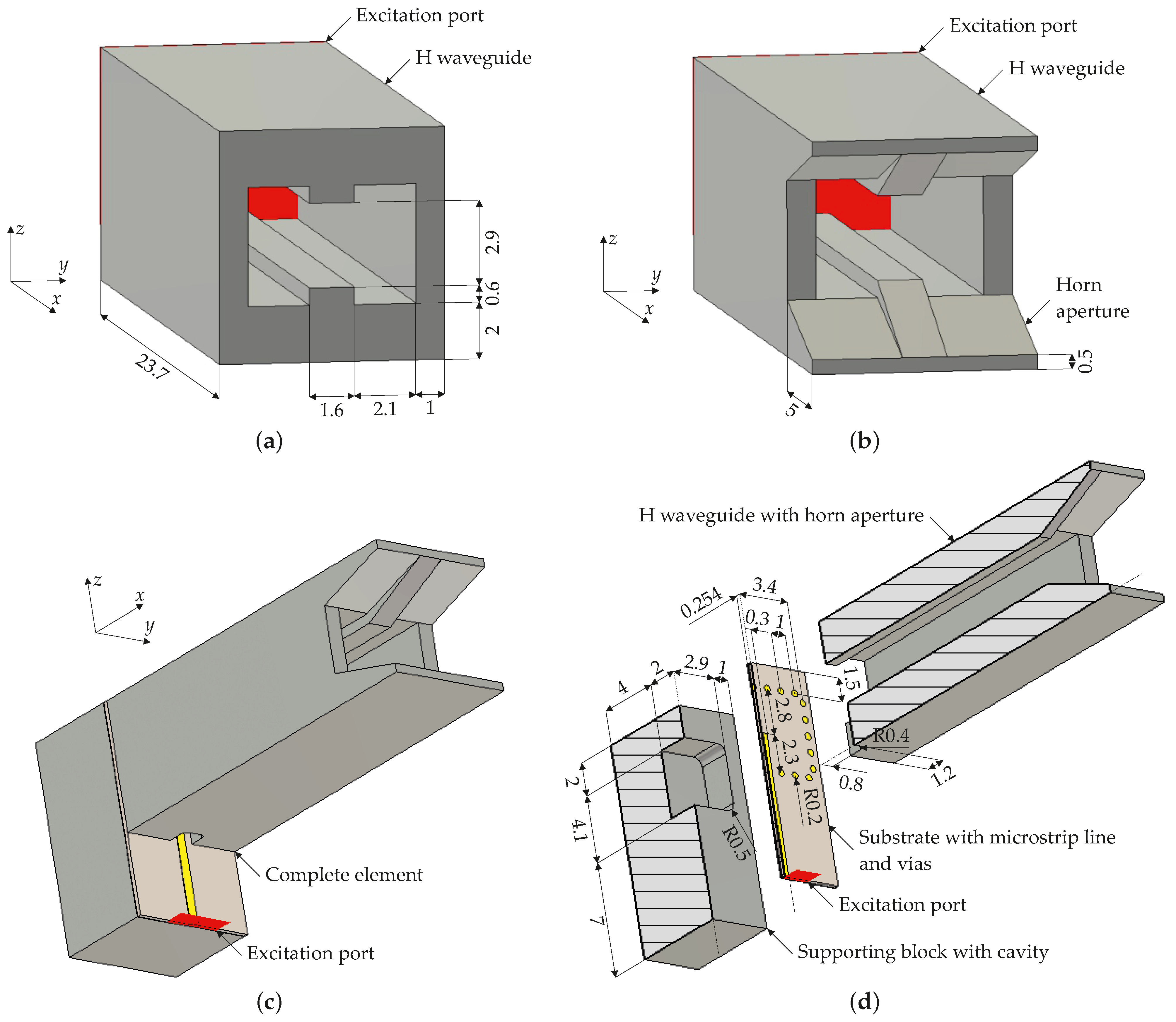
As an element, a metal H waveguide with a horn aperture is chosen, see Figure 1. The element is designed in three successive steps. Firstly, the H waveguide, which possesses a cutoff frequency of GHz with a relative bandwidth of 1:3.3 to safely cover the entire considered frequency band of 24–28 GHz, is formed, see Figure 1a. The ridges incorporated in the waveguide increase its single-mode bandwidth and keep the structure acceptably compact for the lower bound of the bandwidth [27]. The waveguide is excited on one end and radiates from the other end. The radiating end of the waveguide is then shaped as a horn aperture to provide a transition between the waveguide and the free space, see Figure 1b. Finally, the waveguide with the aperture is attached by its excitation end to a microstrip line placed on a metal supporting block with a cavity [28], see Figure 1c,d. Thus, the waveguide is excited by the microstrip line, which is designed on the substrate ASTRA MT77 with relative permittivity and loss factor to have an impedance of 50 . The microstrip line enters the waveguide through a hole that is sized to keep the impedance of the microstrip line at 50 on this discontinuity. The metallic connection of the waveguide and the supporting block is ensured by vias in the substrate. The cavity improves the matching of the transition between the microstrip line and waveguide.
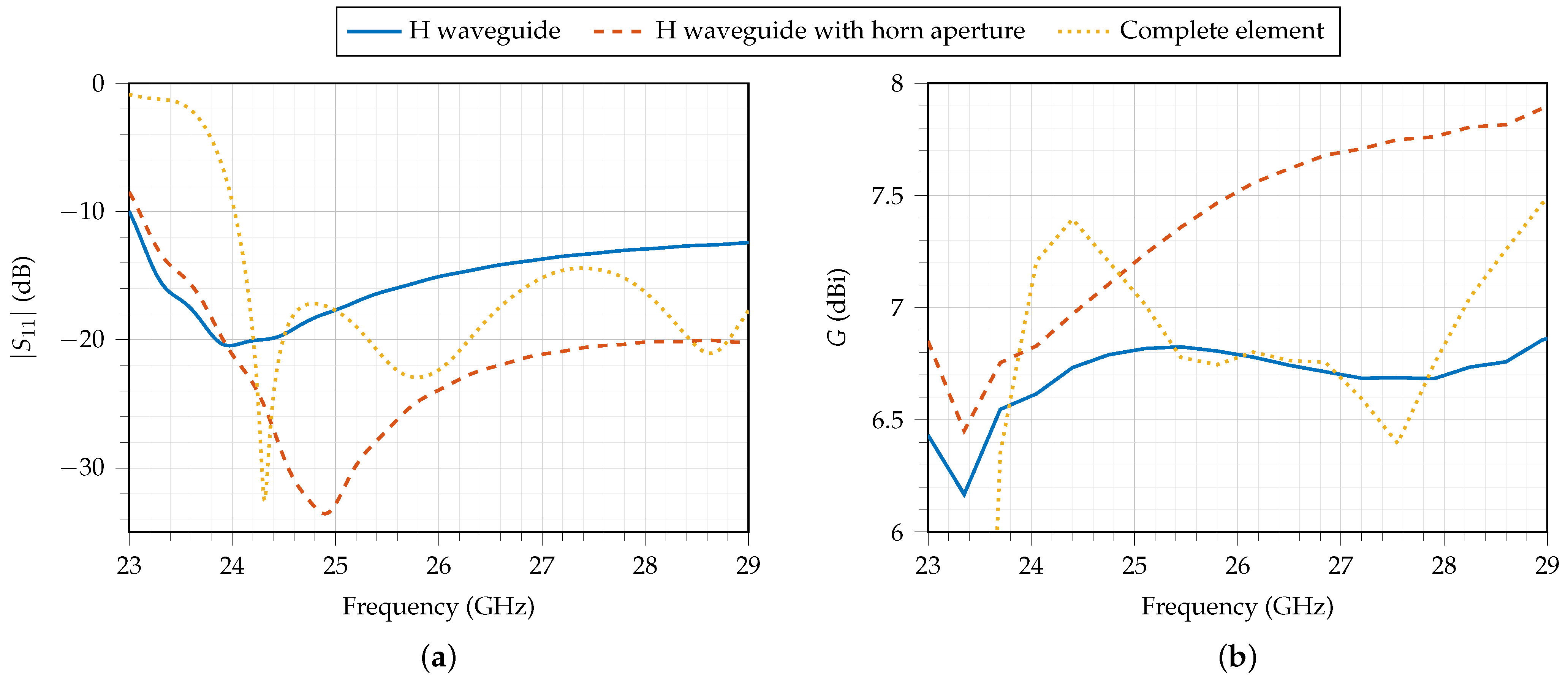
The magnitude of S-parameter and broadside gain G in the direction of the x axis obtained by the simulation for the different design steps from Figure 1 are shown in Figure 2. S-parameter is related to the excitation ports shown in Figure 1. All simulations in this paper are performed in CST Studio Suite 2021 [29]. The following observation can be made: The horn aperture decreases magnitude and increases gain G, i.e., it improves the transition between the waveguide and the free space. On the other hand, the supporting block with the cavity and the microstrip line, which are nevertheless necessary for real applications of the element, cause resonant behavior of the magnitude and decrease the gain G for some frequencies. However, the properties of the element are still acceptable for its use in the array.
3. Antenna Array
The whole structure of the array is specified, and its simulated and measured properties are discussed in this section.
3.1. Structure
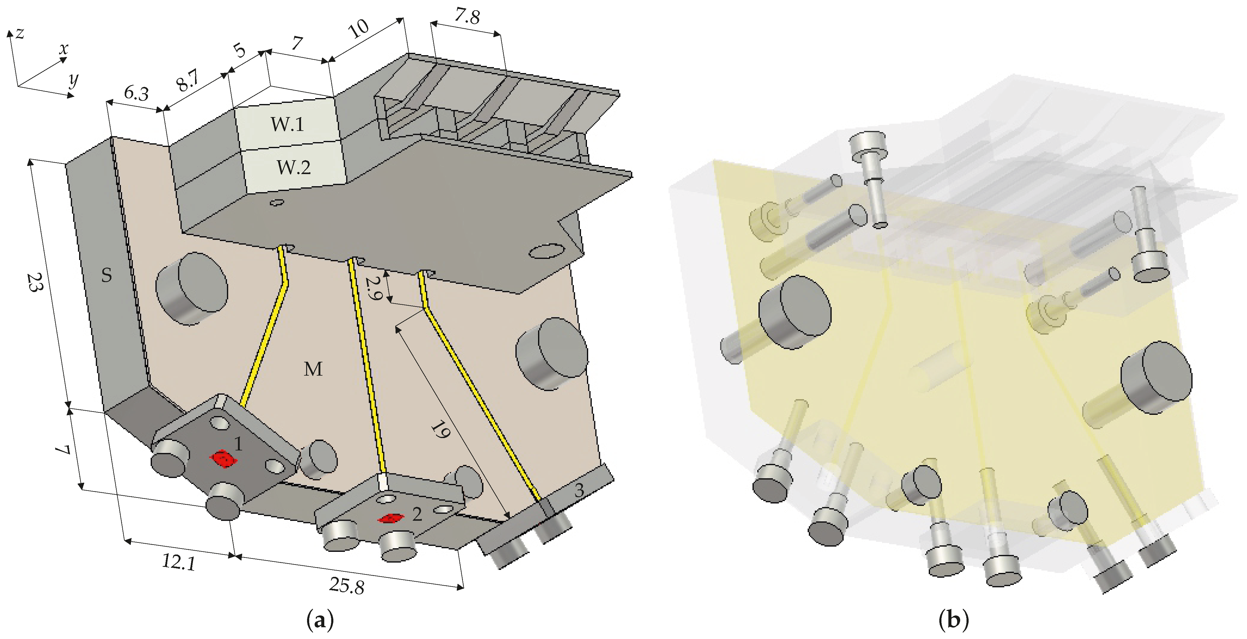
The whole structure of the array is shown in Figure 3 and consists of three elements, described in Section 2, which are linearly distributed along the direction of the y axis. Therefore, the array allows for beam steering in the plane. The elements embedded in the array may exhibit a change in properties due to mutual interactions. In this case, the mutual interactions are mainly caused by the close proximity of the apertures of the individual elements that effectively form the shared aperture of the array. Mutual interactions are minimized by the selected spacing of the elements along the y axis which is mm, where is a free space wavelength at the center frequency of 26 GHz of the considered frequency band.
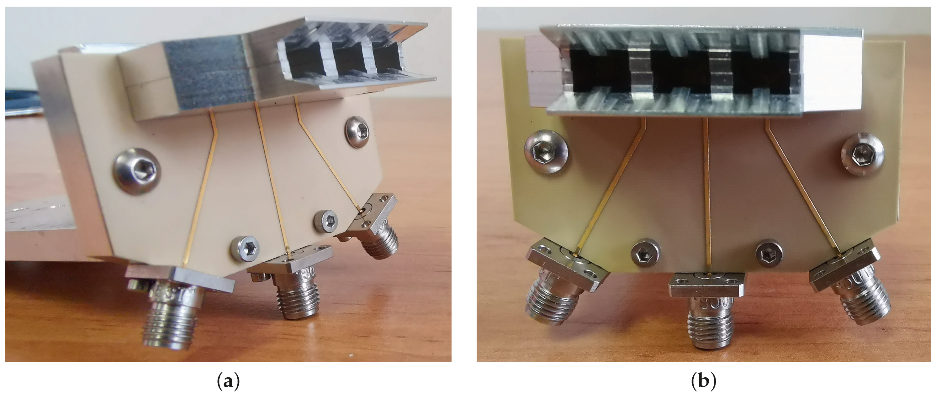
The construction parts of the elements, i.e., the H waveguide with the horn aperture, the supporting block with the cavity, and the microstrip line on the substrate, are merged to the respective construction parts of the array, denoted as W, S, and M in Figure 3, which are screwed together. Parts W and S are made by CNC machining from aluminum. Part W consists of two subparts, W.1 and W.2, to facilitate CNC machining. Part M is manufactured by standard PCB techniques. The microstrip lines are terminated by mm connectors, denoted as 1, 2, and 3 in Figure 3. The physical length of the microstrip line between the connector and excitation end of the waveguide is designed to be equal for all elements to keep the same relative phase shifts and magnitude ratios of excitation signals for the excitation of the waveguides as they are at the connectors. This explains the polygonal shape of the edge for mounting the connectors. The manufactured sample of the array is shown in Figure 4.
3.2. Simulation and Measurement
The manufactured sample was measured and the results were compared with the simulation.
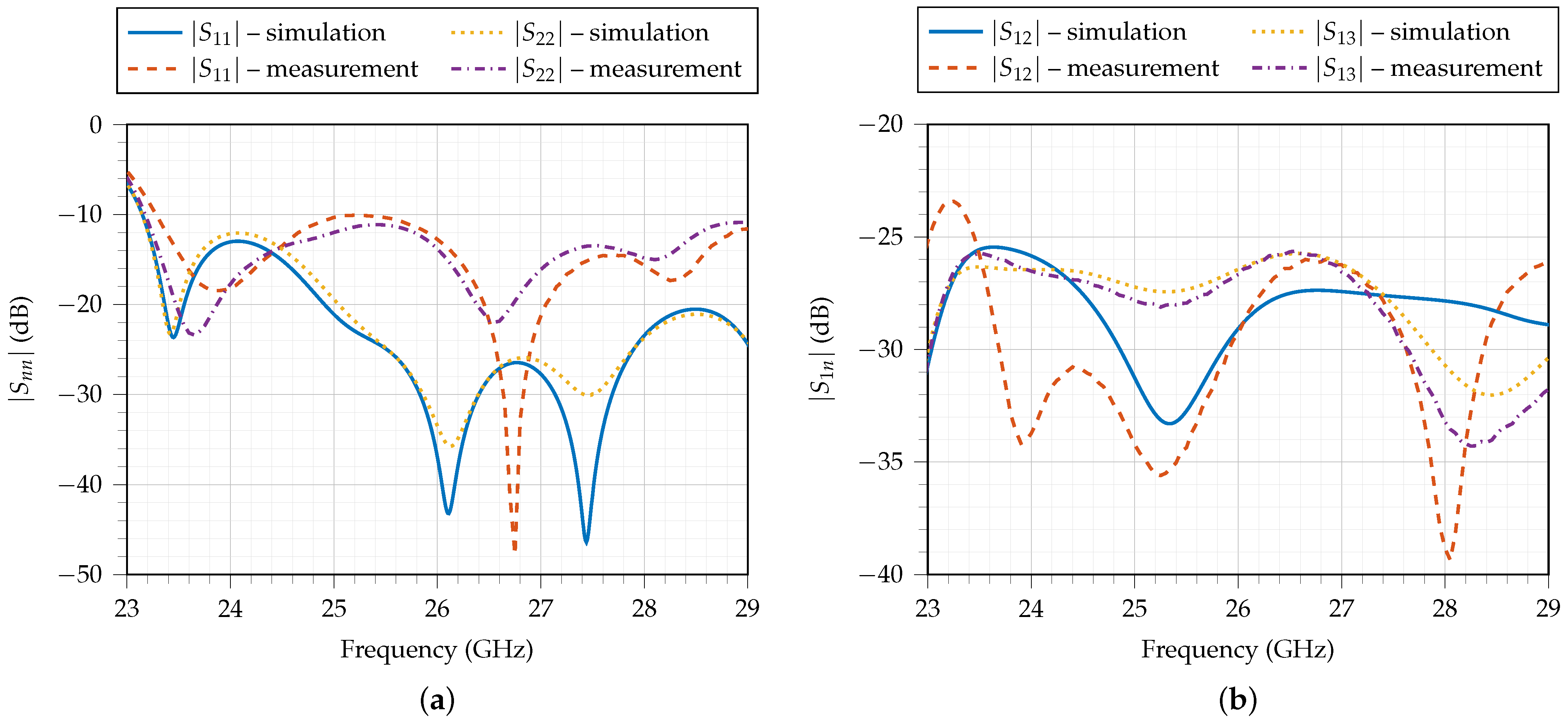
The S-parameters were measured with a vector network analyzer (VNA) Rohde & Schwarz ZVA67 [30]. The magnitude of the simulated and measured S-parameters is shown in Figure 5. The discrepancies of the results of the simulation and measurement are attributed to manufacturing intolerances and the unknown inner structure of the connectors. However, the reflection at the connectors is below dB and the transmission between them is lower than dB in the entire considered frequency band of 24–28 GHz. The low transmission also confirms minimized mutual interactions between the elements.
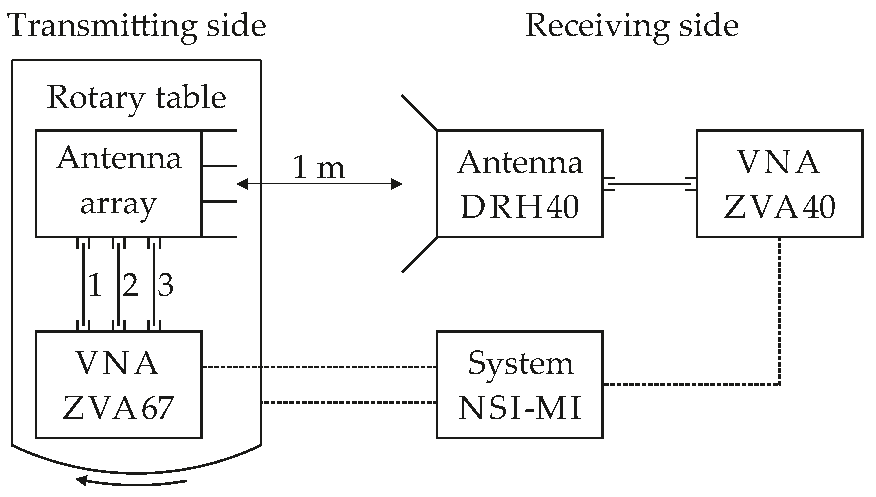
The radiation patterns for a different setting of excitation signals at the connectors were simulated and measured to test the beam-steering performance of the array, and its suitability for use in the microwave photonic link that is also investigated by the authors [25]. The measurement was performed in the anechoic chamber with the help of the NSI-MI Technologies far-field antenna measurement system [31], see Figure 6. On the transmitting side of the system, the VNA Rohde & Schwarz ZVA67 [30] was employed as a transmitter for the excitation of the array. Both the VNA ZVA67 and array were placed on a rotary table. On the receiving side, the double-ridged horn antenna RFspin DRH40 [32] connected to the VNA Rohde & Schwarz ZVA40 [30], serving as a receiver, was used. Apertures of the array and antenna DRH40 were separated by a distance of 1 m.
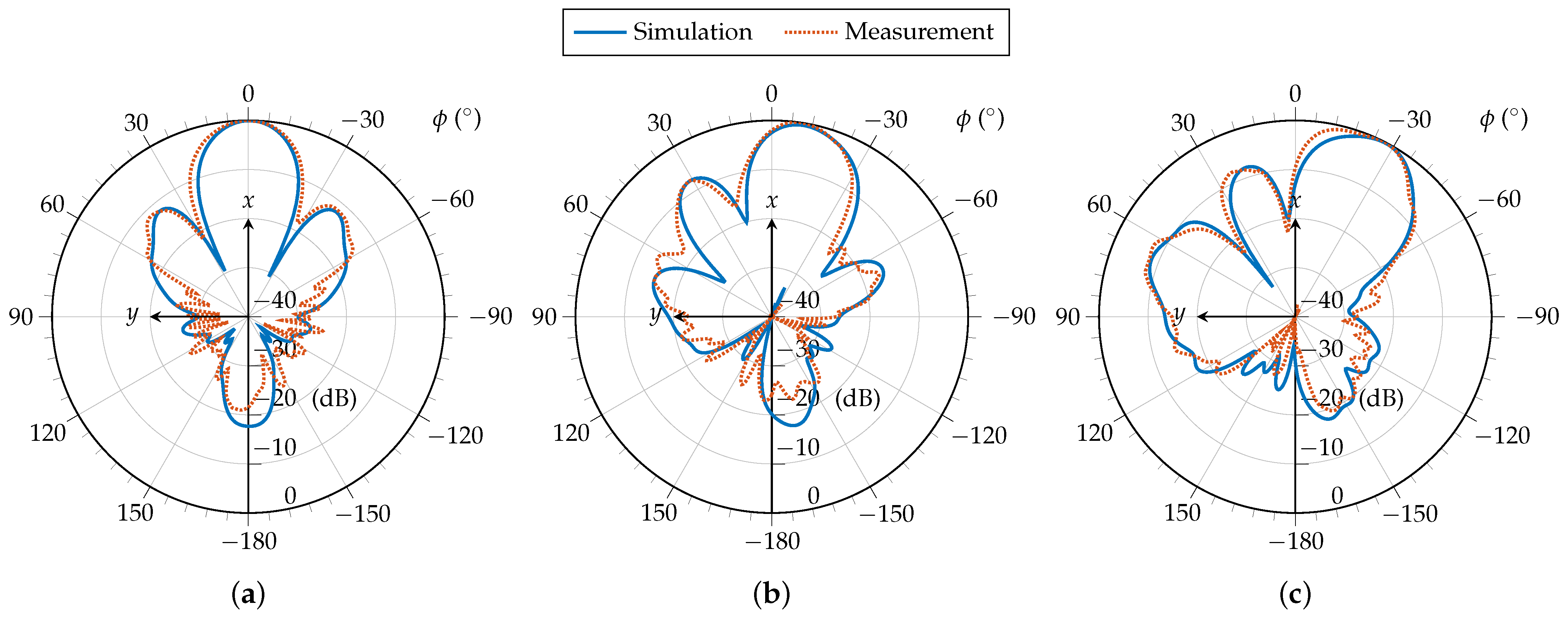
For the microwave photonic link, only beam steering using signal phasing is considered. Thus, the signals at connectors 1, 2, 3 were set with equal magnitudes and different phases . The particular tested combinations of phases with corresponding directivity D and angle in the plane of the main beam at the frequency of 26 GHz are summarized in Table 1. Simulated and measured radiation patterns are shown in Figure 7. Simulated aperture efficiency is . Due to the symmetry of the array, when angle is achieved for progressive phasing then angle is achieved for phasing .
4. Conclusions
A compact three-element shared-aperture waveguide antenna array for the 24–28 GHz microwave-frequency band is presented as a proof-of-concept of an array with steerable directional beam suitable for 5G telecommunication systems. The array is intended for use in a microwave photonic link and is sufficiently steerable only with the progressively phased excitation signals of equal magnitudes. The mutual interactions of the array elements are minimized to keep properties of the individual elements, even if they are embedded and closely spaced in the array. The proposed concept could be simply extended by adding more elements to further increase the directivity and enhance the steering properties of the array.
The main advantages of the proposed array design are ease of mechanical construction, compactness, equal electrical length of the excitation lines, high efficiency and low mutual interactions between the array elements. The array also offers a significant bandwidth due to its elements representing an optimized transition from the microstrip line through the H waveguide with the horn aperture to the free space.
Author Contributions
Conceptualization, P.H.; Investigation, P.H., J.K., T.L. and Z.H.; Validation, V.K.; Visualization, J.K.; Writing—original draft, P.H. and J.K. All authors have read and agreed to the published version of the manuscript.
Funding
This research was funded by the Czech Science Foundation (Project GA20-02046S Antenna Arrays with Quantized Controlling).
Conflicts of Interest
The authors declare no conflict of interest.
References
- Gupta, A.; Jha, R.K. A Survey of 5G Network: Architecture and Emerging Technologies. IEEE Access 2015, 3, 1206–1232. [Google Scholar] [CrossRef]
- Andrews, J.G.; Buzzi, S.; Choi, W.; Hanly, S.V.; Lozano, A.; Soong, A.C.K.; Zhang, J.C. What Will 5G Be? IEEE J. Sel. Areas Commun. 2014, 32, 1065–1082. [Google Scholar] [CrossRef]
- Qiao, J.; Shen, X.S.; Mark, J.W.; Shen, Q.; He, Y.; Lei, L. Enabling Device-to-Device Communications in Millimeter-Wave 5G Cellular Networks. IEEE Commun. Mag. 2015, 53, 209–215. [Google Scholar] [CrossRef]
- Ishii, H.; Kishiyama, Y.; Takahashi, H. A Novel Architecture for LTE-B: C-Plane/U-Plane Split and Phantom Cell Concept. In Proceedings of the 2012 IEEE Globecom Workshops, Anaheim, CA, USA, 3–7 December 2012; pp. 624–630. [Google Scholar] [CrossRef]
- Asai, T. 5G Radio Access Network and Its Requirements on Mobile Optical Network. In Proceedings of the 2015 International Conference on Optical Network Design and Modeling (ONDM), Pisa, Italy, 11–14 May 2015; pp. 7–11. [Google Scholar] [CrossRef]
- User Equipment (UE) Radio Transmission and Reception; Part 2: Range 2 Standalone (Release 17); 3rd Generation Partnership Project; Sophia Antipolis: Valbonne, France, 2021.
- Elgam, A.; Balal, Y.; Pinhasi, Y. Study of 5G-NR-MIMO Links in the Presence of an Interferer. Electronics 2021, 10, 732. [Google Scholar] [CrossRef]
- Bechta, K.; Kelner, J.M.; Ziolkowski, C.; Nowosielski, L. Inter-Beam Co-Channel Downlink and Uplink Interference for 5G New Radio in mm-Wave Bands. Sensors 2021, 21, 793. [Google Scholar] [CrossRef] [PubMed]
- Peethala, D.; Kaiser, T.; Vinck, A.J.H. Reliability Analysis of Centralized Radio Access Networks in Non-Line-of-Sight and Line-of-Sight Scenarios. IEEE Access 2019, 7, 18311–18318. [Google Scholar] [CrossRef]
- Novak, M.H.; Miranda, F.A.; Volakis, J.L. Ultra-Wideband Phased Array for Millimeter-Wave ISM and 5G Bands, Realized in PCB. IEEE Trans. Antennas Propag. 2018, 66, 6930–6938. [Google Scholar] [CrossRef]
- Bah, A.O.; Qin, P.Y.; Ziolkowski, R.W.; Guo, Y.J.; Bird, T.S. A Wideband Low-Profile Tightly Coupled Antenna Array with a Very High Figure of Merit. IEEE Trans. Antennas Propag. 2019, 67, 2332–2343. [Google Scholar] [CrossRef]
- Diawuo, H.A.; Jung, Y.B. Broadband Proximity-Coupled Microstrip Planar Antenna Array for 5G Cellular Applications. IEEE Antennas Wirel. Propag. Lett. 2018, 17, 1286–1290. [Google Scholar] [CrossRef]
- Khalily, M.; Tafazolli, R.; Xiao, P.; Kishk, A.A. Broadband mm-Wave Microstrip Array Antenna with Improved Radiation Characteristics for Different 5G Applications. IEEE Trans. Antennas Propag. 2018, 66, 4641–4647. [Google Scholar] [CrossRef]
- Zhu, S.; Liu, H.; Chen, Z.; Wen, P. A Compact Gain-Enhanced Vivaldi Antenna Array with Suppressed Mutual Coupling for 5G mmWave Application. IEEE Antennas Wirel. Propag. Lett. 2018, 17, 776–779. [Google Scholar] [CrossRef]
- Kindt, R.W.; Pickles, W.R. Ultrawideband All-Metal Flared-Notch Array Radiator. IEEE Trans. Antennas Propag. 2010, 58, 3568–3575. [Google Scholar] [CrossRef]
- Li, A.; Luk, K.M.; Li, Y. A Dual Linearly Polarized End-Fire Antenna Array for the 5G Applications. IEEE Access 2018, 6, 78276–78285. [Google Scholar] [CrossRef]
- Hong, T.; Zheng, S.; Liu, R.; Zhao, W. Design of mmWave Directional Antenna for Enhanced 5G Broadcasting Coverage. Sensors 2021, 21, 746. [Google Scholar] [CrossRef] [PubMed]
- Li, H.; Li, Y.; Chang, L.; Sun, W.; Qin, X.; Wang, H. A Wideband Dual-Polarized Endfire Antenna Array with Overlapped Apertures and Small Clearance for 5G Millimeter-Wave Applications. IEEE Trans. Antennas Propag. 2021, 69, 815–824. [Google Scholar] [CrossRef]
- Sodre, A.C.; da Costa, I.F.; dos Santos, R.A.; Filgueiras, H.R.; Spadoti, D.H. Waveguide-Based Antenna Arrays for 5G Networks. Int. J. Antennas Propag. 2018, 2018, 1–10. [Google Scholar] [CrossRef] [Green Version]
- Ashraf, N.; Sebak, A.R.; Kishk, A.A. End-Launch Horn Antenna Array for Ka-Band 5G Applications. In Proceedings of the 2018 18th International Symposium on Antenna Technology and Applied Electromagnetics (ANTEM), Waterloo, ON, Canada, 19–22 August 2018; pp. 1–2. [Google Scholar] [CrossRef]
- Li, A.; Luk, K.m. Ultra-Wideband Endfire Long-Slot-Excited Phased Array for Millimeter-Wave Applications. IEEE Trans. Antennas Propag. 2021, 69, 3284–3293. [Google Scholar] [CrossRef]
- Yang, B.; Yu, Z.; Dong, Y.; Zhou, J.; Hong, W. Compact Tapered Slot Antenna Array for 5G Millimeter-Wave Massive MIMO Systems. IEEE Trans. Antennas Propag. 2017, 65, 6721–6727. [Google Scholar] [CrossRef]
- Han, I.H.; Woo, J.M. Design of Ridge Waveguide Array Antenna for Radar. In Proceedings of the 2021 Twelfth International Conference on Ubiquitous and Future Networks (ICUFN), Jeju Island, Korea, 17–20 August 2021; pp. 179–183. [Google Scholar] [CrossRef]
- Federico, G.; Caratelli, D.; Theis, G.; Smolders, A.B. A Review of Antenna Array Technologies for Point-to-Point and Point-to-Multipoint Wireless Communications at Millimeter-Wave Frequencies. Int. J. Antennas Propag. 2021, 2021, 1–18. [Google Scholar] [CrossRef]
- Bohata, J.; Komanec, M.; Spacil, J.; Hazdra, P.; Lonsky, T.; Hradecky, Z.; Zvanovec, S. Experimental Demonstration of a Microwave Photonic Link Using an Optically Phased Antenna Array for a Millimeter Wave Band. Appl. Opt. 2021, 60, 1013–1020. [Google Scholar] [CrossRef] [PubMed]
- Kaifas, T.N.; Babas, D.G.; Sahalos, J.N. MIMO Architecture Modelling Utilizing Overlapped Element Antenna Arrays. In Proceedings of the 2019 8th International Conference on Modern Circuits and Systems Technologies (MOCAST), Thessaloniki, Greece, 13–15 May 2019; pp. 1–4. [Google Scholar] [CrossRef]
- Collin, R.E. Foundations for Microwave Engineering, 2nd ed.; John Wiley & Sons: Hoboken, NJ, USA, 2001. [Google Scholar]
- Shih, Y.C.; Ton, T.N.; Bui, L.Q. Waveguide-to-Microstrip Transitions for Millimeter-Wave Applications. In Proceedings of the 1988 IEEE MTT-S International Microwave Symposium Digest, New York, NY, USA, 25–27 May 1988; pp. 473–475. [Google Scholar] [CrossRef]
- CST Studio Suite. Available online: http://www.cst.com (accessed on 16 October 2021).
- Rohde & Schwarz. Available online: https://www.rohde-schwarz.com (accessed on 16 October 2021).
- NSI-MI Technologies. Available online: https://www.nsi-mi.com (accessed on 16 October 2021).
- RFspin Double Ridged Horn Antenna DRH40. Available online: https://www.rfspin.com/product/drh40 (accessed on 16 October 2021).
Figure 1.
Design steps of element of antenna array: (a) the H waveguide, (b) the H waveguide with horn aperture, (c,d) the complete element, i.e., the H waveguide with horn aperture, supporting block with cavity, and microstrip line. Dimensions are in millimeters.
Figure 1.
Design steps of element of antenna array: (a) the H waveguide, (b) the H waveguide with horn aperture, (c,d) the complete element, i.e., the H waveguide with horn aperture, supporting block with cavity, and microstrip line. Dimensions are in millimeters.

Figure 2.
Properties of the design steps of element of antenna array: simulated (a) magnitude of S-parameter and (b) broadside gain G in the direction of x axis.
Figure 2.
Properties of the design steps of element of antenna array: simulated (a) magnitude of S-parameter and (b) broadside gain G in the direction of x axis.

Figure 3.
(a) Whole structure of the antenna array and (b) its mounting screws. Dimensions are in millimeters.
Figure 3.
(a) Whole structure of the antenna array and (b) its mounting screws. Dimensions are in millimeters.

Figure 4.
Manufactured sample of the antenna array: (a) side view and (b) front view.

Figure 5.
Magnitude of simulated and measured S-parameters of antenna array: (a) reflection coefficients , and (b) transmission coefficients , . and due to symmetry of array. Connectors are denoted according to Figure 3.
Figure 5.
Magnitude of simulated and measured S-parameters of antenna array: (a) reflection coefficients , and (b) transmission coefficients , . and due to symmetry of array. Connectors are denoted according to Figure 3.

Figure 6.
Setup for measurement of radiation patterns.

Figure 7.
Cut in plane of simulated and measured radiation patterns for tested combinations of phases of excitation signals of equal magnitudes at the frequency of 26 GHz: (a) , (b) , and (c) .
Figure 7.
Cut in plane of simulated and measured radiation patterns for tested combinations of phases of excitation signals of equal magnitudes at the frequency of 26 GHz: (a) , (b) , and (c) .


Table 1.
Tested combinations of phases with corresponding directivity D and angle in the plane of the main beam at the frequency of 26 GHz.
Table 1.
Tested combinations of phases with corresponding directivity D and angle in the plane of the main beam at the frequency of 26 GHz.
| D | ||
|---|---|---|
| dBi | ||
| dBi | ||
| 12 dBi |
Publisher’s Note: MDPI stays neutral with regard to jurisdictional claims in published maps and institutional affiliations. |
© 2021 by the authors. Licensee MDPI, Basel, Switzerland. This article is an open access article distributed under the terms and conditions of the Creative Commons Attribution (CC BY) license (https://creativecommons.org/licenses/by/4.0/).
Share and Cite
MDPI and ACS Style
Hazdra, P.; Kracek, J.; Lonsky, T.; Kabourek, V.; Hradecky, Z. Shared-Aperture 24–28 GHz Waveguide Antenna Array. Electronics 2021, 10, 2976. https://0-doi-org.brum.beds.ac.uk/10.3390/electronics10232976
AMA Style
Hazdra P, Kracek J, Lonsky T, Kabourek V, Hradecky Z. Shared-Aperture 24–28 GHz Waveguide Antenna Array. Electronics. 2021; 10(23):2976. https://0-doi-org.brum.beds.ac.uk/10.3390/electronics10232976
Chicago/Turabian StyleHazdra, Pavel, Jan Kracek, Tomas Lonsky, Vaclav Kabourek, and Zdenek Hradecky. 2021. "Shared-Aperture 24–28 GHz Waveguide Antenna Array" Electronics 10, no. 23: 2976. https://0-doi-org.brum.beds.ac.uk/10.3390/electronics10232976
Note that from the first issue of 2016, this journal uses article numbers instead of page numbers. See further details here.