Article

Mutual Inductance Calculation of Circular Coils Sandwiched between 3-Layer Magnetic Mediums for Wireless Power Transfer Systems

1
College of Computer and Electrical Engineering, Hunan University of Arts and Science, Changde 415000, China
2
Key Laboratory of Hunan Province for Control Technology of Distributed Electric Propulsion Air Vehicle, Changde 415000, China
3
College of Transportation Engineering, Hunan University of Technology, Zhuzhou 412007, China
*
Author to whom correspondence should be addressed.
Submission received: 29 October 2021 / Revised: 27 November 2021 / Accepted: 2 December 2021 / Published: 6 December 2021
(This article belongs to the Special Issue IoT Applications for Renewable Energy Management and Control)

Abstract

:
The mutual inductance between coils directly affects many aspects of performance in wireless power transmission systems. Therefore, a reliable calculation method for the mutual inductance between coils is of great significance to the optimal design of transmission coil structures. In this paper, a mutual inductance calculation for circular coils sandwiched between 3-layer magnetic mediums in a wireless power transmission system is proposed. First, the structure of circular coils sandwiched between 3-layer magnetic mediums is presented, and then a mutual inductance model of the circular coils is established. Accordingly, a corresponding magnetic vector potential analysis method is proposed based on Maxwell equations and the Bessel transform. Finally, the mutual inductance calculation method for circular coils between 3-layer magnetic mediums is obtained. The correctness of the proposed mutual inductance calculation method is verified by comparing the calculated, simulated, and measured mutual inductance data.

1. Introduction

Wireless Power Transfer (WPT) technology, also known as contactless power transmission (CPT), is a technology that transmits electric energy from a power source to the load without physical contact [1], and the WPT system can be widely used in internet of things(IoT) device power supply [2,3].
The transferred power level and transmission performance are critical for the WPT system which is depend on the mutual inductance and coupling coefficient between the transmitting coil and receiving coil. Hence, mutual inductance must be accurately calculated for the optimal design and better performance of the WPT system.
Many scholars have studied mutual inductance calculation in air media, and reliable results have been obtained from basic calculations of mutual inductance between parallel coaxial circular coils and circular coils at any relative spatial position. Maxwell [3] provided a classical calculation method for the mutual inductance of parallel coaxial circular coils by using an elliptic integral, which laid a solid foundation for mutual inductance calculation. According a decoupling expansion formula for reciprocal distance in cylindrical coordinates, Luo Yao [4] and Slobodan Babic [5] presented the calculations for mutual inductance between parallel circular noncoaxial coils and coaxial circular coils respectively. For the receiving coil with four degrees of freedom, Grover [6] and Xiong Hui [7] have developed a classical mutual inductance calculation method for the noncoaxial coil and an improved calculation method for the mutual inductance coefficient, respectively, while the calculation process is complex. J.T. Conway [8] proposed a relatively simple expression for mutual inductance between air-cored circular coils under coaxial and noncoaxial conditions based on Maxwell equations, which markedly reduced the complexity of the formula. For the mutual inductance between the primary coil and a secondary coil with an arbitrary relative position and arbitrary shape, a linear integral expression is proposed by K.V Poletkin [9]. Slobodan Babic [10] and Luo Yao [11] deduced mutual inductance calculation methods for the secondary coil with any deviation, respectively. Xie Yue [12] deduced a theoretical calculation formula for mutual inductance between a single-turn coil with rectangular sections at arbitrary relative spatial positions. Li Zhongqi [13] provided a complete solution for arbitrary position calculation with high accuracy.
In the WPT system, multilayer magnetic medium, such as a magnetic shielding layer and an electrical shielding layer (aluminum plate, copper plate, ferrite core, and so on), are added to the resonant coils [14,15] for reducing electromagnetic radiation and energy loss, and gathering the magnetic flux; therefore, the transmission efficiency can be improved by increasing the mutual inductance between the primary coil and the secondary coil. At present, the mutual inductance between circular coils with a magnetic medium is mainly calculated based on Maxwell equations, electromagnetic field initial conditions, and boundary conditions. J.R. Claycomb [16] obtained an impedance calculation formula for two coaxial circular coils with a one-sided magnetic medium by the Poisson equation, Maxwell equation, and boundary conditions of magnetic potential. Furthermore, the impedance calculation formula between two circular coils with a single-layer magnetic medium was provided. W.G. Hurley [17] deduced the calculation method for mutual inductance by solving the electric field strength of a circular current alternating electromagnetic field, the Fourier Bessel transform was used to calculate the mutual inductance, which substantially simplifies the calculation formula. He deduced and solved more complex partial differential equations with the same method as that in [17]. Hence, the calculation formulas for mutual inductance between circular coils with a one-sided magnetic medium and circular coils sandwiched between magnetic media are obtained under the condition of single-layer media with finite magnetic thickness [18,19]. W. A. Roshen [20] used the current imaging method to calculate the mutual inductance for two circular coils that are both sandwiched between magnetic medium of finite thickness. However, this method was more complex and was difficult to solve with programming. The above works are applied to parallel circular coaxial coils; therefore, works on a parallel circular noncoaxial coils are also being carried out synchronously. JesúsAcero [21], Y.P. Su [22] and JesúsAcero [23,24] deduced mutual inductance calculation methods for circular coils sandwiched between no more than double-layer magnetic mediums, respectively; complex derivations are used to solve intermediate variables and the calculation works are difficult.
In this paper, a mutual inductance calculation for circular coils sandwiched between 3-layer magnetic mediums is first studied, and a magnetic vector potential analysis method is proposed. Next, a corresponding simulation model and measurement platform are established. The accuracy of the calculation method is preliminarily verified by comparing simulated and calculated mutual inductance values. Finally, the correctness of the proposed mutual inductance calculation method is verified by comparing calculated, simulated, and measured mutual inductance data.

2. Modeling of Mutual Inductance for Circular Coils Sandwiched between 3-Layer Magnetic Mediums

This section consists of three parts. First, the model of circular coils sandwiched between 3-layer magnetic mediums is introduced. Second, the calculation method for the electromagnetic field magnetic vector potential based on circular coils with a single-layer magnetic medium is presented [15]. Among these, the boundary conditions of 3-layer magnetic media are mainly analyzed, and then the magnetic vector potential is discussed layer by layer through the region method. On this basis, the variables are separated by the Fourier Bessel integral transform, and the formula for the magnetic vector potential is obtained by solving a huge set of equations. In sum, the mutual inductance calculation method for circular coils with 3-layer magnetic mediums on two sides is acquired for the first time according to the relationship between the magnetic vector potential and mutual inductance.

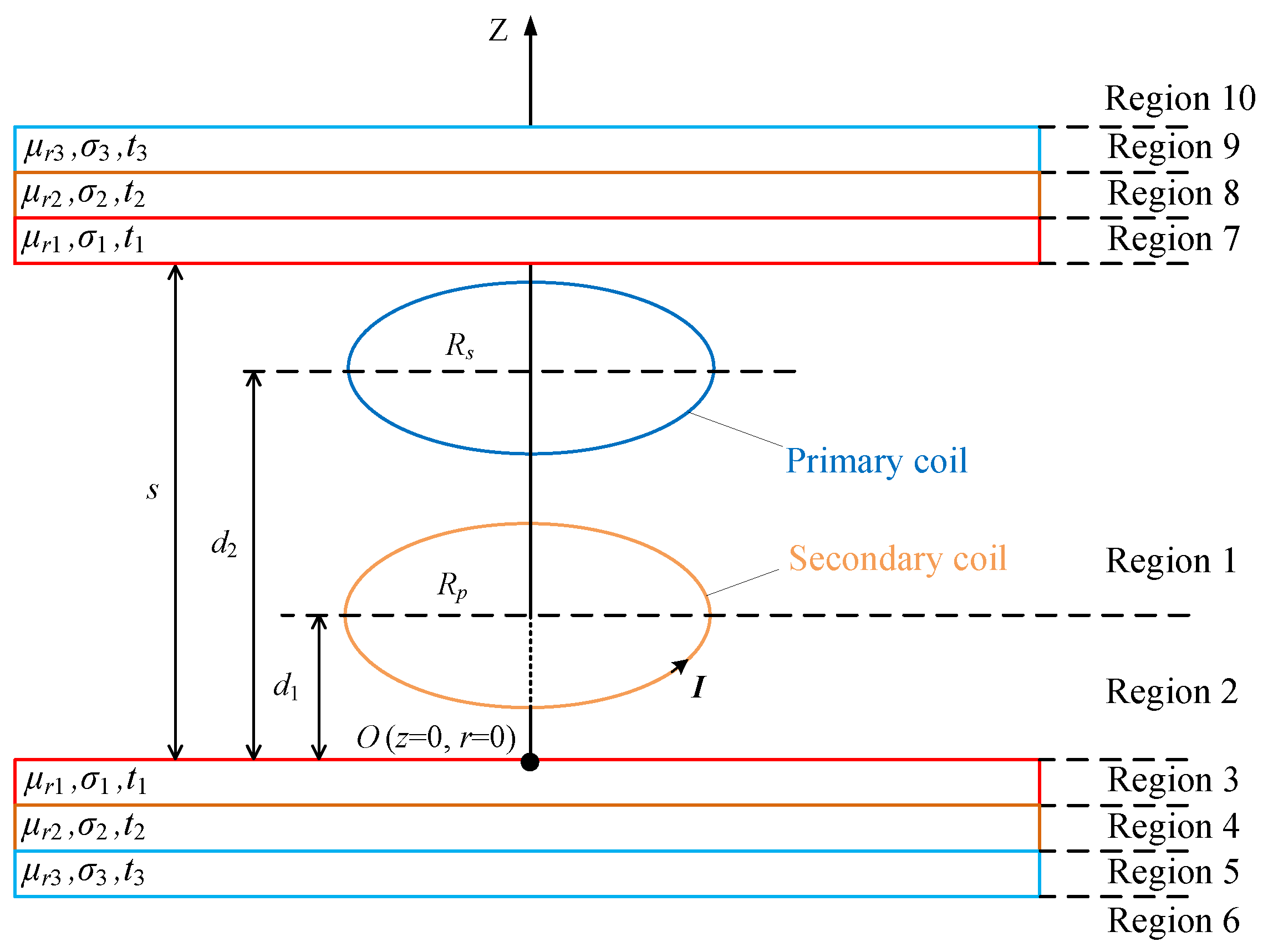
2.1. Model of Mutual Inductance

The structural model of circular coils sandwiched between 3-layer magnetic mediums is shown in Figure 1, which can be divided into three components in a sandwich structure. The middle layer includes primary and secondary coils, as well as Region 1 and Region 2, which belong to the air layer. For the upper and lower layers, Regions 3 to 10 on both sides belong to linear, uniform, isotropic, and horizontally placed magnetic dielectric layers. In addition, the parameters μ r , σ , and t are the relative permeability, conductivity, and thickness of the corresponding magnetic mediums, and R p and R s are the radii of the primary coil and secondary coil, respectively. A cylindrical coordinate system with O as the coordinate origin is established, where the Z-axis is perpendicular to the horizontal plane and passes through the center of the primary coil. Then, the parameters d 1 and d 2 are the center heights of the primary coil and the secondary coil, respectively, and S is the distance between the upper and lower magnetic dielectric layers. Since the dielectric layer and the coil are placed symmetrically and horizontally, the distance between the upper and lower magnetic dielectric layers is s = d 2 + d 1 . In this model, the sinusoidal current through the primary coil can be expressed as I = I 0 e j w t .

2.2. Magnetic Vector Potential Analysis

In the quasi-static magnetic field system in Figure 1, the magnetic vector potential A (which refers to the dynamic potential of the magnetic vector potential) generated by the sinusoidal current in the primary circular coil satisfies the following formula [15]:
2 A = μ I + μ σ A t + μ ε 2 A t 2 + μ ( 1 / μ ) × ( × A ) ,
where μ is the permeability, σ is the conductivity, and ε is the dielectric constant. In the formula, the value of μ σ A / t is much larger than the value of μ ε 2 A / t 2 , and μ ε 2 A / t 2 is negligible at low frequencies. In linear, homogeneous, and isotropic media, ( 1 / μ ) = 0 . Therefore, Equation (1) can be written as:
2 A = μ I + μ σ A t .
According to the characteristics of the time-varying electromagnetic field generated by circular coils, the initial conditions of the electromagnetic field of circular coils sandwiched between 3-layer magnetic mediums are as follows:
A r = 0 A ϕ = A A z = 0 A / ϕ = 0 ,
where A ϕ is the component of A in the ϕ direction, and A has the only component in the ϕ direction. Based on Equation (2) and initial condition Equation (3), the partial differential equation for the magnetic vector potential can be obtained as presented below:
2 A ϕ r 2 + 2 A ϕ z 2 + 1 r A ϕ r A ϕ r 2 j ω μ σ A ϕ + μ I δ r R p r d 1 = 0 .
The current of the primary coil is expressed as an impulse function in this model because only current is present in the primary coil. Applying the first-order Fourier Bessel integral transform yields [17]:
A * k 1 , z = 0 A r 1 , z r J 1 k r d r .
The variables of A can be separated, where J 1 ( k r ) represents the first-order Bessel function with the variable k r , and the essence of k is a spatial frequency. Then, the differential equations that can be easily solved are as follows:
d 2 A ϕ * d z 2 k 2 A ϕ * j ω μ σ A ϕ * + μ I R p J 1 k R p z d 1 = 0 .
Based on Equation (6), the general solution for the magnetic vector potential for each region can be obtained ( σ = 0 when the magnetic medium is air):
R e g i o n 1 A 1 * = A e k z + B e k z d 1 z < s R e g i o n 2 A 2 * = C e k z + 1 D e k z 0 z < d 1 R e g i o n 3 A 3 * = F e η 1 z + G e η 1 z t 1 z < 0 R e g i o n 4 A 4 * = I e η 2 z + K e η 2 z t 1 + t 2 z < t 1 R e g i o n 5 A 5 * = L e η 3 z + M e η 3 z t 1 + t 2 + t 3 z < t 1 + t 2 R e g i o n 6 A 6 * = N e k z z < t 1 + t 2 + t 3 R e g i o n 7 A 7 * = P e η 1 z + Q e η 1 z t 1 z < 0 R e g i o n 8 A 8 * = R e η 2 z + T e η 2 z t 1 + t 2 z < t 1 R e g i o n 9 A 9 * = U e η 3 z + V e η 3 z t 1 + t 2 + t 3 z < t 1 + t 2 R e g i o n 10 A 10 * = X e k z s + t 1 + t 2 + t 3 z .
In Equation group (7), A, B, C, D, F, G, I, K, L, M, N, P, Q, R, T, U, V, and X represent constant coefficients:
η i = k 2 + j ω μ 0 μ r i σ i i = 1 , 2 , 3
According to Maxwell’s classical theory [3], on the longitudinal interface of the medium in the time-varying electromagnetic field, boundary conditions apply to electric field strength E and magnetic field strength H :
n × E 1 E 2 = 0 n × H r 1 H r 2 = J .
In the electromagnetic field in Figure 1, the electric field intensity E = E ϕ has only one component along the direction ϕ . Moreover, the electric field intensity is the same as the direction of the magnetic vector potential according to E = j w A . Therefore, Equation (9) shows that the electromagnetic field in Figure 1 has the following boundary conditions:
A ϕ + = A ϕ n × H r + A r = J ϕ = I 0 δ r R p z d 1 .
Based on the electromagnetic field formula × A = μ H , the relationship between magnetic vector potential A and magnetic field intensity H is:
1 r r · A ϕ r = μ 0 μ r H Z A ϕ z = μ 0 μ r H r .
From A * in each region represented by Equation (7), an equation group containing 18 equations can be acquired by using boundary condition (10) on each horizontal edge interface. Accordingly, the 18 unknowns in Equation (7) can be solved by simultaneous equations, and the expressions of A and B can be obtained according to the recursive methods for each of the two equations such that A 1 * in Region 1 is
A 1 * = μ 0 2 k I R p J 1 k R p f z
where,
f z = α t 1 , t 2 , t 3 + 1 · e k z d 1 α t 1 , t 2 , t 3 β t 1 , t 2 , t 3 e 2 k s 1 + e k z + d 1 α t 1 , t 2 , t 3 β t 1 , t 2 , t 3 e 2 k s .
α ( t 1 , t 2 , t 3 ) = 1 + m 2 1 m 2 ϕ 3 k e 2 η 3 t 3 1 + m 1 e η 2 ( t 1 + t 2 ) e ( η 1 η 2 ) t 1 + 1 m 2 1 + m 2 ϕ 3 k e 2 η 3 t 3 1 m 1 e η 2 ( t 1 + t 2 ) e ( η 1 + η 2 ) t 1 + ϕ 1 k 1 + m 2 1 m 2 ϕ 3 k e 2 η 3 t 3 1 m 1 e η 2 ( t 1 + t 2 ) e ( η 1 + η 2 ) t 1 + 1 m 2 1 + m 2 ϕ 3 k e 2 η 3 t 3 1 + m 1 e η 2 ( t 1 + t 2 ) e ( η 2 η 1 ) t 1 ϕ 1 k 1 + m 2 1 m 2 ϕ 3 k e 2 η 3 t 3 1 + m 1 e η 2 ( t 1 + t 2 ) e ( η 1 η 2 ) t 1 + 1 m 2 1 + m 2 ϕ 3 k e 2 η 3 t 3 1 m 1 e η 2 ( t 1 + t 2 ) e ( η 1 + η 2 ) t 1 + 1 + m 2 1 m 2 ϕ 3 k e 2 η 3 t 3 1 m 1 e η 2 ( t 1 + t 2 ) e ( η 1 + η 2 ) t 1 + 1 m 2 1 + m 2 ϕ 3 k e 2 η 3 t 3 1 + m 1 e η 2 ( t 1 + t 2 ) e ( η 2 η 1 ) t 1
β ( t 1 , t 2 , t 3 ) = 1 + m 1 1 + m 2 ϕ 3 k e 2 η 3 t 3 η 2 t 2 + 1 m 2 e η 2 t 2 e η 1 t 1 + 1 m 1 1 m 2 ϕ 3 k e 2 η 3 t 3 2 η 2 ( s + t 1 ) η 2 t 2 + 1 + m 2 e η 2 t 2 e η 1 t 1 + ϕ 1 k 1 m 1 1 + m 2 ϕ 3 k e 2 η 3 t 3 η 2 t 2 + 1 m 2 e η 2 t 2 e η 1 t 1 + 1 + m 1 1 m 2 ϕ 3 k e 2 η 3 t 3 2 η 2 ( s + t 1 ) η 2 t 2 + 1 + m 2 e η 2 t 2 e η 1 t 1 ϕ 1 k 1 + m 1 1 + m 2 ϕ 3 k e 2 η 3 t 3 η 2 t 2 + 1 m 2 e η 2 t 2 e η 1 t 1 + 1 m 1 1 m 2 ϕ 3 k e 2 η 3 t 3 2 η 2 ( s + t 1 ) η 2 t 2 + 1 + m 2 e η 2 t 2 e η 1 t 1 + 1 m 1 1 + m 2 ϕ 3 k e 2 η 3 t 3 η 2 t 2 + 1 m 2 e η 2 t 2 e η 1 t 1 + 1 + m 1 1 m 2 ϕ 3 k e 2 η 3 t 3 2 η 2 ( s + t 1 ) η 2 t 2 + 1 + m 2 e η 2 t 2 e η 1 t 1
m 1 = μ r 1 η 2 μ r 2 η 1 , m 2 = μ r 2 η 3 μ r 3 η 2
ϕ i k = η i k μ r i η i k + μ r i .
Applying the inverse Fourier Bessel integral transform [17] yields:
A r , z = 0 A * k , z k J 1 k r d k .
According to Equation (12), the magnetic vector potential of Region 1 can be solved as follows:
A 1 = μ 0 2 I R p 0 J 1 k r J 1 k R p f z d k .

2.3. Mutual Inductance Calculation

In region 1, the induced voltage generated by the primary coil current in the secondary coil is:
V = E d l = 2 π R s E R s , d 2 = j 2 π ω R s A R s , d 2
Z p s = V I = j ω μ 0 π R p R s 0 J 1 k R s J 1 k R p f d 2 d k .
According to Equation (19), the mutual inductance formula between single-turn circular coils sandwiched between 3-layer magnetic mediums is as follows:
M p s = R e Z p s j ω = R e μ 0 π R p R s 0 J 1 k R s J 1 k R p f d 2 d k .
For the multiturn plane spiral coil, each turn can be approximately regarded as a circular coil; therefore, the mutual inductance of the plane spiral coil can be calculated by the following Equation (23):
M = p = 1 N p s = 1 N s M p s ,
where N p is the number of turns of the primary coil, N s is the number of turns of the secondary coil, p represents the primary coil of turn p, s indicates the secondary coil of turn s, and M p s is the mutual inductance between the primary coil of turn p and the secondary coil of turn s. The radius of the outer turn will have one more turn space than the radius of the inner turn. Then, the radius parameter should change based on the number of turns during superposition calculation.

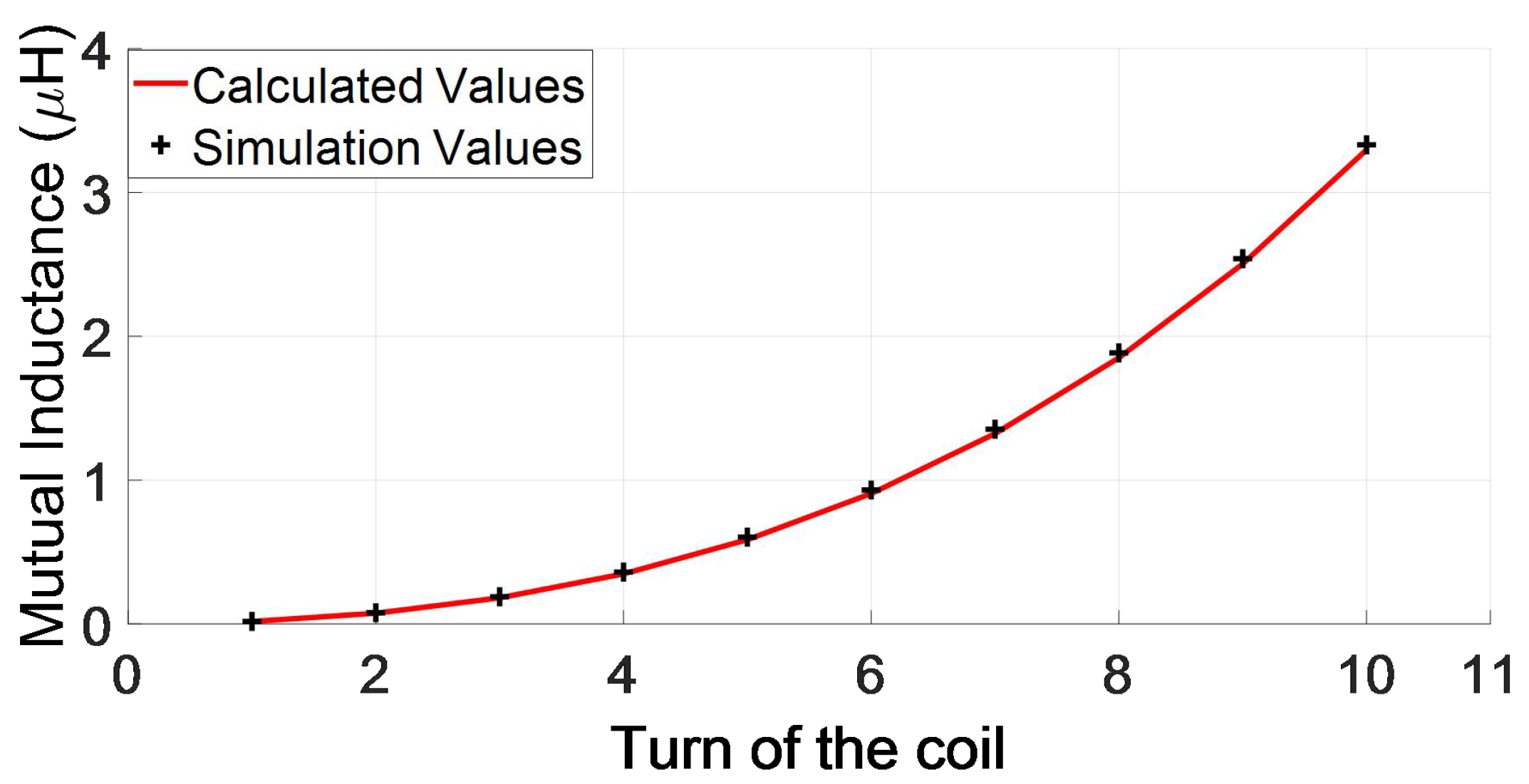
3. Simulation and Experimental Verification

In this section, the accuracy of calculation Equation (22) is first verified by simulation. Then, an experimental platform frame is designed, and a coil is created for an actual mutual inductance measurement. At the same time, a simulation model and experimental model of circular coils sandwiched between 3-layer magnetic mediums are also introduced. Furthermore, the dimensions and parameters of the coils and magnetic mediums in the model are given, as well as some parameters of the measurement device.
The calculated mutual inductance M c , simulated value M s , and measured value M m of circular coils sandwiched between 3-layer magnetic mediums are compared and analyzed in this section. Among these, the error rate δ 1 of M c and M s and the error rate δ 2 between M c and M m are defined by the following formulas:
δ 1 = M s M c M s
δ 2 = M m M c M m .
M c is obtained by calculation with MATLAB, and M s is solved by finite element simulation with ANSYS Maxwell electromagnetic analysis software. M m is acquired by measuring the actual mutual inductance with an IM3536 impedance analyzer, and the current frequency of the impedance analyzer is set to 85 kHz.

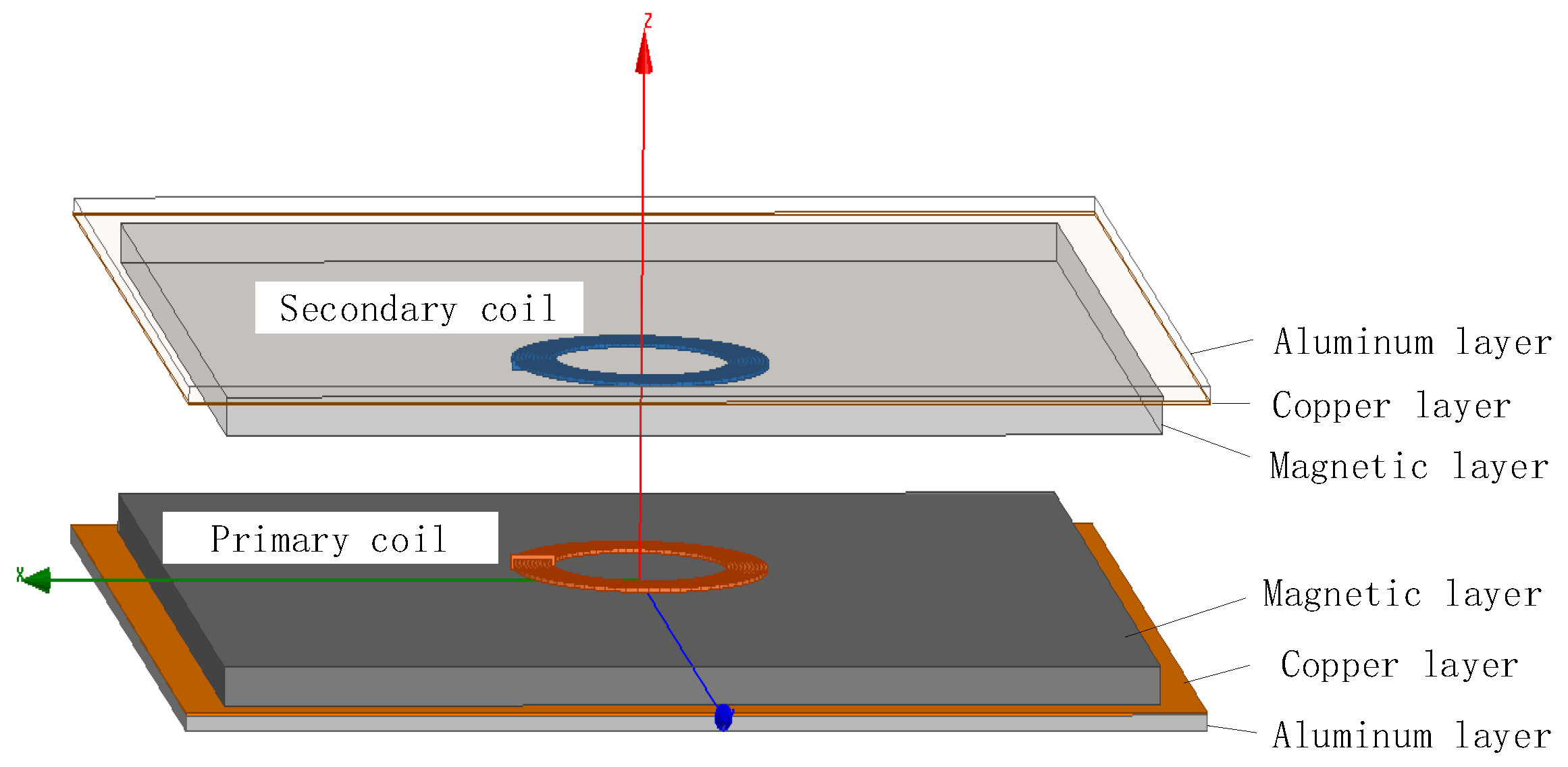
3.1. Simulation Model

In this section, the mutual inductance simulation model of circular coils sandwiched between 3-layer magnetic mediums is established based on the model in Figure 1, as shown in Figure 2. The dielectric layer and coil are placed symmetrically and horizontally; hence, the distance between the upper and lower magnetic dielectric layers is s = d 2 + d 1 , and the transmission distance is D = d 2 d 1 .
The mutual inductance of coils with different radii must be observed to verify the correctness of Equation (22). Therefore, the initial radii of the primary coil and secondary coil are set to 51 mm, and the variable quantity of the radius is 2.4 mm. In addition, the number of turns increases from 1 to 10, and the transmission distance D is 120 mm. Other parameters of coils and magnetic mediums are shown in Table 1.
The calculated mutual inductance M c and simulated value M s of circular coils sandwiched between 3-layer magnetic mediums with different turns are shown in Table 2. The calculated and simulated mutual inductance values are intuitively compared in Figure 3. Table 2 and Figure 3 show that the value calculated using Equation (22) is in good agreement with the simulated value, which preliminarily verifies the correctness of the calculation formula for circular coils sandwiched between 3-layer magnetic mediums. For the single-turn coil, the error rate between the calculated and simulated mutual inductance values is very low because simulated modeling of the single-turn coil is established with the circular coil. For coils exceeding one turn, the coil simulation model is established with a plane spiral, resulting in a slightly larger error.

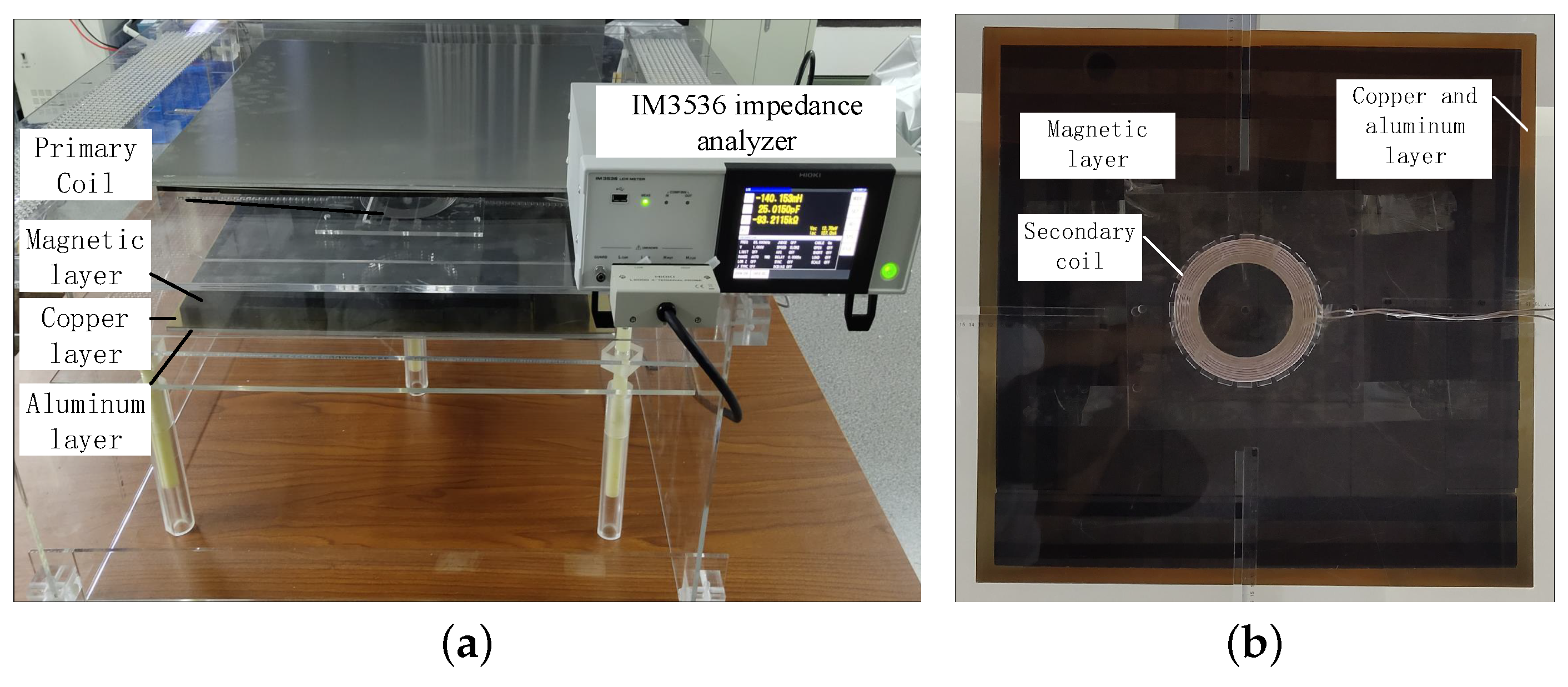
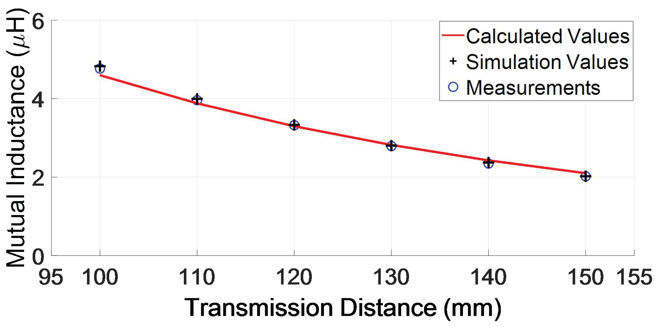
3.2. Experimental Verification

To verify the correctness of Equation (22) corresponding to the model in Figure 1, the measurement framework for mutual inductance shown in Figure 4 is designed. The front view and vertical view of the measurement device are presented; the framework is composed of acrylic and nylon, which have good magnetic flux permeability and do not affect the measured mutual inductance value. Moreover, the whole measurement process is carried out overhead on a wooden table to reduce environmental interference.
The specific parameters of the coils and magnetic mediums of the simulation model and the measurement device are shown in Table 3. The dielectric layer and the coil are placed symmetrically; thus, the distance between the upper and lower magnetic dielectric layers is s = d 2 + d 1 , and the transmission distance is D = d 2 d 1 .
In the measurement, the two coils inevitably use longer terminals to connect to the IM3536 impedance analyzer. On this basis, winding two terminals can reduce the influence of terminals on mutual inductance. The measurement is carried out on the wooden table and acrylic experimental framework to reduce the influence of the surrounding environment on the mutual inductance and obtain accurate measurement results. In addition, wood and acrylic are nonmagnetic materials, and their influence on mutual inductance can be ignored.

3.3. Analysis of Experimental Results

The calculated value M c , simulated value M s , and measured value M m of mutual inductance are shown in Table 4. Among these, the transmission distance D increases from 100 mm to 150 mm in steps of 10 mm. Table 4 and Figure 5 show that the mutual inductance between coils decreases with increasing transmission distance D.
In addition, the error rate δ 1 of the simulated and calculated values is within 5%, as well as the error rate δ 2 of the measured and calculated values. In general, the correctness of the mutual inductance calculation for circular coils sandwiched between 3-layer magnetic mediums, shown in Equation (22), is verified by simulated and measured mutual inductance results.

4. Conclusions

In this paper, the mutual inductance calculation for circular coils sandwiched between 3-layer magnetic mediums was thoroughly studied. First, the partial differential equation of the magnetic vector potential was obtained through the relationship between the magnetic vector potential and current density in a uniform magnetic medium. Next, the Bessel transform was used to separate variables to acquire the solution of the magnetic vector potential by combining the Maxwell equation and the boundary conditions of the time-varying electromagnetic field. Thus, the calculation formula for mutual inductance between circular coils with 3-layer magnetic mediums on two sides was given. Finally, the mutual inductance data obtained by calculations, the ANSYS Maxwell finite element model analysis, and the experiments on the actual coil were compared. The reliability and correctness of the proposed calculation were verified from the low error rate between the three types of data.

Author Contributions

Conceptualization, M.Y. and Z.L.; methodology, M.Z. and M.Y.; software, M.Z. and J.W.; validation, M.Z. and Z.L.; formal analysis, M.Z. and M.Y.; investigation, Z.L.; resources, Z.L.; data curation, M.Z.; writing—original draft preparation, M.Z. and J.W.; writing—review and editing, M.Y. and Z.L.; visualization, Z.L.; supervision, J.W.; project administration, M.Y. and Z.L.; funding acquisition, M.Y. and Z.L. All authors have read and agreed to the published version of the manuscript.

Funding

This research was funded by the Program of Natural Science Foundation of Hunan Province (Grant no. 2019jj40200), the Program of Natural Science Foundation of Hunan Province (Grant no. 2020jj6061), the Research Foundation of Education Bureau of Hunan Province, China (Grant no. 19B393), the Scientific And Technological Innovation And Development Project of Changde District (Grant no. 2020C083), and the Science And Technology Innovation Program of Hunan Province (Grant no. 2021GK2010).

Conflicts of Interest

The authors declare no conflict of interest.

References

  1. Lee, J.; Lee, K. Effects of Number of Relays on Achievable Efficiency of Magnetic Resonant Wireless Power Transfer. IEEE Trans. Power Electron. 2020, 35, 6697–6700. [Google Scholar] [CrossRef]
  2. Lin, W.; Ziolkowski, R.W. A Circularly Polarized Wireless Power Transfer System for Internet-of-Things (IoT) Applications. In Proceedings of the 2020 4th Australian Microwave Symposium (AMS) IEEE, Sydney, Australia, 13–14 February 2020. [Google Scholar]
  3. Yao, Y. Energy Efficiency Characterization in Heterogeneous IoT System With UAV Swarms Based on Wireless Power Transfer. IEEE Access 2020, 8, 967–979. [Google Scholar] [CrossRef]
  4. Luo, Y. A new method for mutual inductance calculation of parallel axis circular coil. Trans. China Electrotech. Soc. 2016, 31, 31–37. [Google Scholar]
  5. Babic, S.I.; Akyel, C. New analytic-numerical solutions for the mutual inductance of two coaxial circular coils with rectangular cross section in air. IEEE Trans. Magn. 2006, 42, 1661–1669. [Google Scholar] [CrossRef]
  6. Grover, F.W. The calculation of the mutual inductance of circular filaments in any desired positions. Proc. IRE 1944, 32, 620–629. [Google Scholar] [CrossRef]
  7. Xiong, H.; Liu, L. Improved calculation method of mutual inductance coefficient at any relative position. IEEE Trans. Magn. 2018, 24, 7–11. [Google Scholar]
  8. Conway, J.T. Inductance calculations for non-coaxial coils using Bessel functions. Sens. World 2007, 43, 1023–1034. [Google Scholar]
  9. Poletkin, K.V.; Korvink, J.G. Efficient calculation of the mutual inductance of arbitrarily oriented circular filaments via a generalisation of the Kalantarov-Zeitlin method. J. Magn. Magn. Mater. 2019, 48, 10–20. [Google Scholar] [CrossRef] [Green Version]
  10. Babic, S.; Sirois, F. Mutual inductance calculation between circular filaments arbitrarily positioned in space alternative to grover’s formula. IEEE Trans. Magn. 2010, 46, 3591–3600. [Google Scholar] [CrossRef]
  11. Luo, Y.; Chen, B.C. Mutual Inductance Calculations of Inclined Axial Air-Core Circular Coils with Rectangular Cross-Sections. Trans. China Electrotech. Soc. 2012, 20, 132–136. [Google Scholar]
  12. Xie, Y.; Pan, W.L. Mutual inductance calculation method of arbitrary space positioned coils. Electr. Mach. Control 2016, 20, 63–67. [Google Scholar]
  13. Li, Z.Q.; Zhang, M. Mutual inductance calculation of circular coils arbitrary positioned with magnetic tiles for wireless power transfer system. IET Power Electron. 2020, 13, 3522–3527. [Google Scholar] [CrossRef]
  14. Zhang, X.; Zhang, P.C. Magnetic Shielding Design and Analysis for Wireless Charging Coupler of Electric Vehicles Based on Finite Element Method. Trans. China Electrotech. Soc. 2016, 31, 71–79. [Google Scholar] [CrossRef]
  15. Zhang, X.; Zhang, P.C. Analytical solutions to eddy-current probe-coil problems. J. Appl. Phys. 1968, 39, 2829–2838. [Google Scholar]
  16. Claycomb, J.R.; Tralshawala, N. Theoretical investigation of eddy-current induction for nondestructive evaluation by superconducting quantum interference devices. IEEE Trans. Magn. 2000, 36, 292–298. [Google Scholar] [CrossRef]
  17. Hurley, W.G.; Duffy, M.C. Calculation of self and mutual impedances in planar magnetic structures. IEEE Trans. Magn. 1995, 31, 2416–2422. [Google Scholar] [CrossRef]
  18. Hurley, W.G.; Duffy, M.C. Calculation of self- and mutual impedances in planar sandwich inductors. IEEE Trans. Magn. 1997, 33, 2282–2290. [Google Scholar] [CrossRef]
  19. Hurley, W.G.; Duffy, M.C. Impedance formulas for planar magnetic structures with spiral windings. IEEE Trans. Ind. Electron. 1999, 46, 271–278. [Google Scholar] [CrossRef]
  20. Roshen, W.A. Effect of finite thickness of magnetic substrate on planar inductors. IEEE Trans. Magn. 1990, 26, 270–275. [Google Scholar] [CrossRef]
  21. Carretero, C.; Acero, J. Modeling mutual impedances of loaded non-coaxial inductors for induction heating applications. IEEE Trans. Magn. 2008, 44, 4115–4118. [Google Scholar] [CrossRef]
  22. Su, Y.P.; Liu, X. Mutual inductance calculation of movable planar coils on parallel surfaces. IEEE Trans. Power Electron. 2009, 24, 1115–1123. [Google Scholar] [CrossRef]
  23. Acero, J.; Alonso, R. Modeling of planar spiral inductors between two multilayer media for induction heating applications. IEEE Trans. Magn. 2006, 42, 3719–3729. [Google Scholar] [CrossRef]
  24. Acero, J.; Carretero, C. Analysis of the mutual inductance of planar-lumped inductive power transfer systems. IEEE Trans. Ind. Electron. 2013, 60, 410–420. [Google Scholar] [CrossRef]
Figure 1. Simplified schematic of the WPT system based on magnetically coupling resonator.
Electronics 10 03043 g001
Figure 2. Mutual inductance model of circular coil sandwiched between 3-layer magnetic mediums.
Electronics 10 03043 g002
Figure 3. Mutual inductance model of circular coil sandwiched between 3-layer magnetic mediums.
Electronics 10 03043 g003
Figure 4. Experimental device of a circular coil sandwiched between 3-layer magnetic mediums. (a) The front view of the measurement framework; (b) The vertical view of the measurement framework.
Electronics 10 03043 g004
Figure 5. Comparison of Mutual inductance with vertical misalignment.
Electronics 10 03043 g005
Table 1. Parameters of coils and magnetic mediums.
ParameterValue
Initial radius of primary coil R p 51 mm
Initial radius of secondary coil R s 51 mm
Turns of primary coil N p 1∼10
Turns of secondary coil N s 1∼10
Diameter of the field excitation conductor2.4 mm
Height of primary coil d 1 2 mm
Height of secondary coil d 2 5 mm
Side length of the magnetic medium550 mm
Thickness of magnetic medium t 1 15 mm
Relative permeability of magnetic medium μ r 1 1000
Conductivity of magnetic medium σ 1 0.01 (S/m)
Side length of copper600 mm
Thickness of copper t 2 1 mm
Conductivity of magnetic copper σ 2 5.8 × 10 7 (S/m)
Side length of aluminum600 mm
Thickness of aluminum t 3 6 mm
Relative permeability of aluminum μ r 3 1
Conductivity of magnetic aluminum σ 3 3.8 × 10 7 (S/m)
Table 2. Parameters of coils and magnetic mediums.
N p N s M c ( μ H) M s ( μ H) δ 1
110.01720.01741.15%
220.07460.07794.24%
330.18160.18873.76%
440.34820.36053.41%
550.58590.60392.98%
660.90660.93122.64%
771.32361.35362.22%
881.85091.88501.81%
992.50352.54001.44%
10103.29733.33191.04%
Table 3. Parameters of coils and magnetic mediums.
ParameterValue
Initial radius of primary coil R p 51 mm
Initial radius of secondary coil R s 51 mm
Turns of primary coil N p 10
Turns of secondary coil N s 10
Variable quantity of the radius85 kHz
Diameter of the field excitation conductor2.4 mm
Height of primary coil d 1 2 mm
Height of secondary coil d 2 5 mm
Side length of the magnetic medium550 mm
Thickness of magnetic medium t 1 15 mm
Conductivity of magnetic medium σ 1 0.01 (S/m)
Side length of copper600 mm
Thickness of copper t 2 1 mm
Relative permeability of copper μ r 2 1
Conductivity of magnetic copper σ 2 5.8 × 10 7 (S/m)
Side length of aluminum600 mm
Thickness of aluminum t 3 6 mm
Relative permeability of aluminum μ r 3 1
Table 4. Mutual inductance with vertical misalignment.
D (mm) M c ( μ H) M s ( μ H) M m ( μ H) δ 1 δ 1
1004.59764.82694.76704.75%3.55%
1103.88033.99543.96052.88%2.02%
1203.29733.33193.32361.04%0.79%
1302.82012.80292.79150.61%1.02%
1402.42692.37222.34632.31%3.44%
1502.10062.02232.02143.87%3.92%
Publisher’s Note: MDPI stays neutral with regard to jurisdictional claims in published maps and institutional affiliations.

