
Computational Simulation of Microflaw Detection in Carbon-Fiber-Reinforced Polymers


1
Centre for Mechanical Engineering, Materials and Processes, Univ Coimbra, 3030-290 Coimbra, Portugal
2
Centre for Informatics and Systems, Univ Coimbra, 3030-790 Coimbra, Portugal
*
Author to whom correspondence should be addressed.
Electronics 2022, 11(18), 2836; https://0-doi-org.brum.beds.ac.uk/10.3390/electronics11182836
Submission received: 3 August 2022
/
Revised: 5 September 2022
/
Accepted: 6 September 2022
/
Published: 8 September 2022
(This article belongs to the Special Issue Non-destructive Testing by Ultrasounds)
Abstract
:The evaluation of microflaws in carbon-fiber-reinforced composite laminate (CFRP) via ultrasound requires the knowledge of some important factors in addition to its structural composition. Since the laminates are heterogeneous, the high-frequency requirements to acquire high-resolution signals have limitations due to the great scattering that prevents good signal-to-noise ratios. Additionally, the ultrasonic probe’s spatial and lateral resolution characteristics are important parameters for determining the detectability level of microflaws. Modelling appears as a good approach to evaluating the abovementioned factors and the probability of detection of defects in the micron range because it makes it possible to reduce the time and cost associated with developments based on experimental tests. Concerning the subject of this work, simulation is the best way to evaluate the detectability level of the proposed defects since experimental samples are not available. In this work, the simulation was implemented using the Matlab k-Wave toolbox. A 2D matrix for mimicking a CFRP was constructed with 1 μm of resolution. Four different defect types in the micron range were created in the matrix. The simulated and experimental results presented good agreement. It was concluded that the highest frequency probe that could be used to detect the simulated defects without ambiguity was 25 MHz.
Keywords:
carbon-fiber-reinforced polymer; modelling; pulse-echo; simulation; ultrasounds; microflaw1. Introduction
Carbon-fiber-reinforced polymers (CFRP) are composed of a bonding polymer (such as epoxy) and carbon fibers in addition to other components. CFRP are used in high-performance applications in which high strength-to-weight ratio and rigidity are required [1]. The mechanical properties of composites are anisotropic and depend on the content and arrangement of fibers [1,2]. The advances in the manufacturing processes led to a great increase in applications of CFRP in industries as aerospace, automotive, defense, sport, civil engineering, music, and others [3]. However, the integrity and performance of these composites may be compromised by diverse flaws occurring during the manufacturing process or along their life span [3]. Small internal flaws commonly presenting no external signs remain undetected, ending in drastic structural failures [4].
Several non-destructive techniques (NDT) have been used to evaluate the structural integrity of composites. The most common and well-established are visual inspection, acoustic emission, ultrasonic testing, infrared thermography, terahertz testing, shearography, digital image correlation, X-ray, and neutron imaging [5]. Ultrasound testing is one of the most widely used NDT techniques for quality control and service integrity evaluation due to its relatively low cost and high resolution in defect detection [6]. Several recent studies use different ultrasound-based techniques for evaluating the integrity of composites. The effect of the distance between the impact point and holes on the fatigue life of glass fiber/epoxy laminates was evaluated by Santos [7]. Detection and characterization of delamination and rich resin in thick composites with waviness were performed by Zhang using a multifrequency ultrasonic method [8]. The influence of interlayer delaminations on the static and fatigue behavior of composite laminates was studied by Reis [9]. Another widely studied topic is related to the evaluation of damages induced by low-velocity impact, generally using the ultrasonic C-scan technique to evaluate the damage’s shape and size [10,11]. PZT sensors in a pitch-and-catch configuration and the Lamb wave symmetrical mode could also be used to characterize damages [12]. More recently, air-coupled C-scan systems working in through transmission mode have demonstrated great effectivity in detecting such defects, with resolutions comparable to the classical immersion approach [10]. Guided waves are another promising technique to locate delaminations in composite plates [13,14].
Simulation allows the prediction of the propagation of ultrasonic waves in a particular medium, enabling the optimization of configurations and procedures for NDT. Currently, the improvement of computational resources makes the implementation of numerical or grid-based methods possible. Recent works have used finite element methods (FEM) to accurately mimic wave propagation through a rather complex material [15,16,17]. The major drawback of elastic wave models based on low-order finite difference or finite element schemes is the large number of grid points per wavelength required to avoid numerical dispersion. As an alternative, the k-Wave, which is an available third-party MATLAB toolbox, makes use of a Fourier domain pseudospectral method for faster simulation and reconstruction of photoacoustic wave fields in a way that uses less memory and is user-friendly [18,19]. Fewer spatial and temporal grid points are needed for accurate simulations [18]. Recently many authors have used the k-Wave toolbox in NDT applications related to attenuation in ultrasonic computed tomography [20], guided waves in layered structures [21,22], time domain power law attenuation in breast and liver tissues [23], one-sided ultrasonic non-destructive evaluation [24], high intensity focused ultrasound [25], nonlinear ultrasound propagation in absorbing media [26], ultrasonic transducers field modelling [27], 3-D ultrasound imaging [28], and A-scan ultrasound simulation in ophthalmology [29].
In the present study, the authors intend to model and simulate microflaws in CFRP laminates, evaluating their detectability level. The importance of simulating deals with the difficulty to have experimental samples with such small defects. Additionally, simulation appears as the first approach to assist in evaluating of the probability of detection for a particular testing technique. The results showed good agreement with the experimental data. The obtained backscattered signal works as a metric for defining the detectability of the different types of simulated defects.
2. Materials and Methods
Simulation was implemented using the k-Wave toolbox of Matlab [18]. This toolbox allows the time domain simulation of acoustic wave propagating in 1D, 2D, and 3D, making use of a numerical model. The simulation was based on the experimental approach using an ultrasonic immersion system working in pulse-echo mode [10].
To simulate using the k-Wave toolbox, several parameters must be previously specified, such as the computational grid representing the medium through which the acoustic waves will propagate, the acoustic parameters characterizing the medium (propagation velocity and density), the probe (source/sensor) profile, and the excitation pulse. Attenuation was considered a posteriori.
2.1. Simulation Parameters
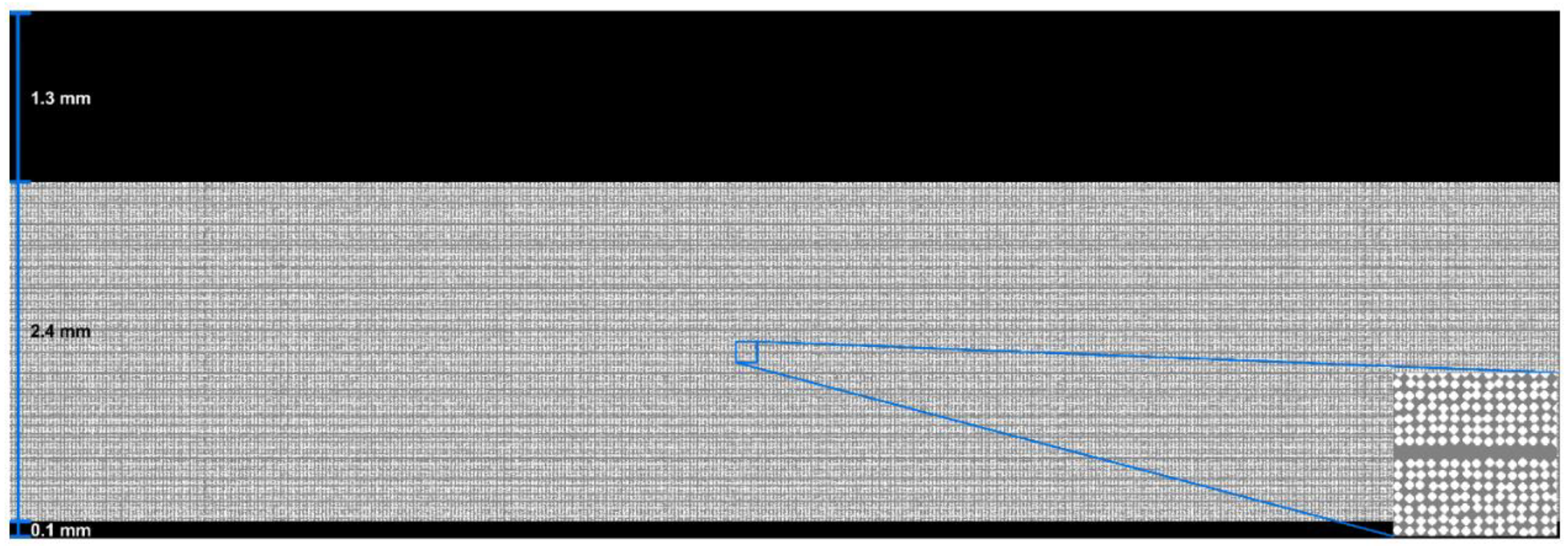
The 2D matrix for CFRP representation was constructed in Matlab with a spatial resolution of 1 μm (Figure 1). It is composed of carbon fibers embedded in an epoxy matrix with a pseudorandom distribution and with about 47% fiber content. The fiber diameter was set to 9 μm, the plies have a 0.15 mm thickness with a stacking sequence of 0°, and the ply junctions (epoxy) were represented with a thickness of 13 μm. The structure has 16 plies, a thickness of 2.4 mm, and a lateral dimension of 12 mm.
The CFRP is inspected using the immersion pulse-echo method. A water layer of 1.3 mm on the top was used to avoid multiple reflected pulses that could overlap with those from the composite.
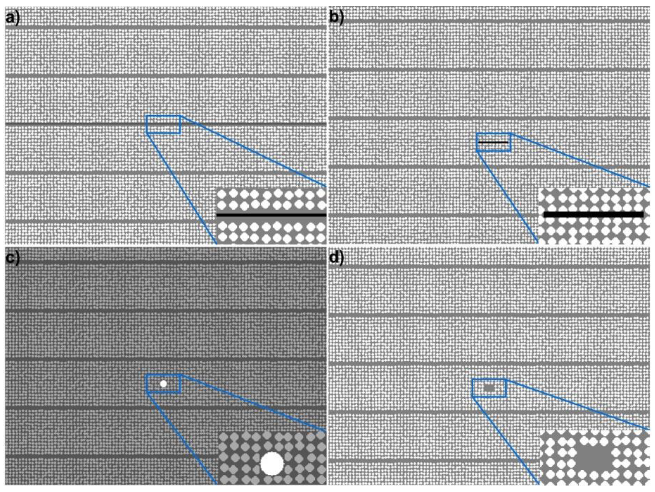
To evaluate the potential of the simulation tool in detecting very small flaws, four distinct imperfections were introduced based on [3], as shown in Figure 2. Figure 2a illustrates a total debonding 4 μm thick between plies 6 and 7. Figure 2b shows a bar-shaped delamination of 4 μm × 100 μm located at the center of ply 6. The acoustic properties of the media inside the delamination and debonding gaps correspond to that of water since the representation of epoxy/air interfaces are not viable with the k-Wave toolbox (more details in the Discussion section). A foreign body 23 μm in diameter was inserted at the center of ply 7, as shown in Figure 2c. Oil acoustic properties were attributed to this flaw since diverse particles, such as grease, hair, dirt, etc., can infiltrate during the manufacturing process [3]. The fourth simulated defect characterizes broken fibers, where the profile of some fibers is changed by epoxy, as illustrated in Figure 2d.
The acoustic properties of the CFRP components, water, and oil used in the simulation were adopted from Kinsler et al. [30] and Ono [31] and are presented in Table 1.
Since the simulated probe works in pulse-echo mode, the same probe profile (mask) was defined as source and sensor. The source was excited with a four-cycle burst of 25 MHz central frequency.
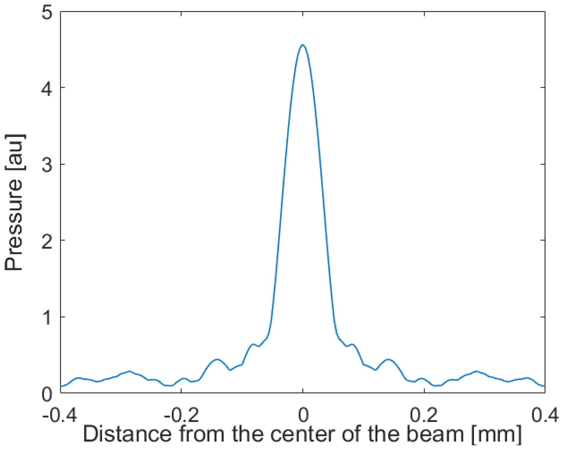
The radiation pattern of a 25 MHz transducer with 5 mm active diameter and 28 mm focal length used in the simulation is presented in Figure 3. The effective width of the ultrasonic field considered is 0.8 mm at the focus, as shown in Figure 4. This allowed the width of the computational grid to be greatly reduced from 12 mm to 0.8 mm, with a consequent decrease in processing time.
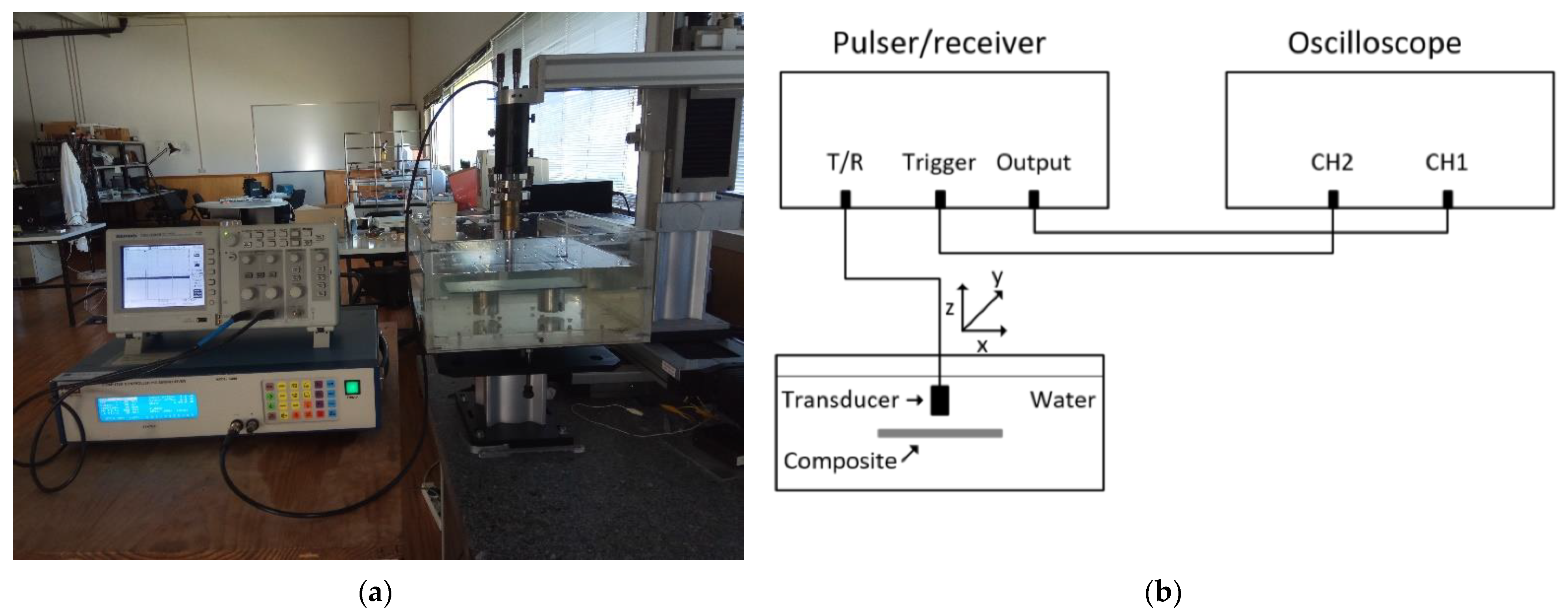
For simulated signals, attenuation effects were introduced in a post-processing step, as proposed by other authors [32]. For that purpose, the attenuation α in the CFRP composite was obtained using the experimental setup presented in Figure 5 and the method used in [33]:
where L is the sample thickness, AS the reflected signal on the sample surface, R the reflection coefficient at water-sample boundary, D the diffraction correction coefficient for the sample path, and A1 the reflected pulse from the sample back surface. The reflection coefficient was obtained from the knowledge of the sample’s and water’s acoustic impedances. The acoustic impedance of the CFRP sample was calculated using its density [30] and respective ultrasonic velocity by measuring the time of flight of a propagated wave. The reflection coefficient resulted in R = 0.52. Due to the small CFRP thickness, when compared to the transducer beam width at the focus, the diffraction correction coefficient was considered unitary. For the measurement of AS and A1 amplitudes, ten signals were collected from different locations to consider the structure spatial variations. An attenuation of 6.03 Np/cm was obtained.
2.2. Experimental Setup
The ultrasonic experimental system illustrated in Figure 5 is composed by a Panametrics pulser/receiver model 5800, a Krautkramer immersion broadband focused transducer model JAP F-25.3.1 with 25 MHz central frequency, 28 mm focal length, 5 mm active diameter (like the simulated one), and a Tektronix digital oscilloscope model TDS1002B. After propagation through the composite samples, the ultrasound signals are collected, amplified, and filtered by the pulser/receiver. Then, they are displayed on the oscilloscope and saved for further processing. The transducer is moved using a computer-controlled micropositioning system.
Ten signals were collected from different locations on a 4 mm2 surface to consider the structure’s spatial variations, and an average signal was obtained.
The CFRP samples were prepared in a laboratory from high-strength unidirectional carbon pre-preg TEXIPREG HS 160 REM (PREPREG from SEAL, Legnano, Italy) and processed in agreement with the manufacturer recommendations using the autoclave/vacuum bag molding process. The composite production encompassed the following procedures: making the hermetic bag and applying a 0.05 MPa vacuum, heating to 125 °C at 3–5 °C × min−1 rate, applying a pressure of 0.5 MPa when a temperature of 120 or 125 °C was reached, maintaining the pressure and temperature over 60 min, cooling down to room temperature while maintaining the pressure, and finally removing the part from the mold. The laminates were composed of 16 plies that were 2.4 mm thick with a stacking sequence of 0°. The acoustic properties of the CFRP samples are presented in Table 2.
3. Results
The simulated and experimental signals of a non-defective CFRP structure are presented in Figure 6. The reflected pulse on the composite surface (higher amplitude pulse) followed by low amplitude pulses from the ply boundaries is easily observed. The reflected pulse from the bottom of the plate is also visible in both figures; however, some filtering effect is observed in the experimental signal, leading to a lower amplitude and lower frequency content.
Then, the A-scan signals were obtained for the different simulated defects. Figure 7a presents the signal propagated through the structure of Figure 2a. The high-amplitude reflected pulse, marked in the graph by an arrow, demonstrates that delamination is detected without ambiguity.
The resulting A-scan signal for the structure in Figure 2b is represented in Figure 7b. Despite having lower amplitude, the reflected pulse clearly identifies the presence of the considered delamination. To evaluate the detectability degree of the simulation system, the transverse dimension of delamination was decreased as long as simulations carried on. It was found that the detectability limit was around 50 μm width and 4 μm thickness.
For the oil spherical inclusion of Figure 2c, the A-scan signal shown in Figure 7c was observed. The system was able to detect such a small inclusion, though the reflected pulse is of very low amplitude. This means that for such types of inclusions, the used size corresponds to the detectable limit.
Finally, for the case of broken fibers (Figure 2d) placed in the center of ply 8, it was found that detection is only possible when 18 fibers (nine in width and two in thickness) were substituted with epoxy. The resulting signal is presented in Figure 7d.
In Table 3, the minimum detectable dimensions for the defects considered in the study are summarized.
4. Discussion
This work aimed to evaluate through simulations the detectability of microflaws in composite structures by using high frequency ultrasound. For that goal, the k-Wave toolbox of Matlab was used to determine how far it is possible to decrease the size of defects and still detect them with a good signal-to-noise ratio. The study encompassed four distinct simulated flaws, such as a complete debonding, a small delamination such as a bar, a spherical inclusion (foreign body), and broken fibers. For the considered defects and using a high-frequency transducer of 25 MHz (observed to be the limit frequency for the studied structures), it was possible to detect delaminations 50 μm in width, a spherical inclusion with a diameter of about 23 μm, and broken fibers with an extension of about 100 μm (nine fibers wide and two fibers thick).
The simulated signals are noise-free, which differs from real situations, in which lower signal-to-noise ratios (SNR) are present. In these circumstances, small echoes from eventual microflaws can be hidden in the raw data. However, it is predictable that post-processing approaches like signal averaging will improve the SNR, making the detection of very small echoes possible.
When representing the microflaws, some limitations were found. First, it was not possible to consider air as propagation medium inside debonding or delamination because the k-Wave toolbox has some limitations on representing the acoustic wave propagation at boundaries of high acoustic impedance mismatch (as in the case of an air–epoxy boundary). For this reason, the flaws were considered to have the acoustic properties of water. Note that in real situations, when air is present, the reflected echoes at the boundaries are higher in amplitude and that the flaw signals will be more pronounced than in simulation. For similar reasons, on air testing simulations, the representation of air flaws (as void or porosity) was not possible.
Another limitation is related to the large size of the composite matrix required to represent resolutions of 1 μm, which prevents the implementation of 3D matrices with the available computational resources. However, some simulated studies related to the propagation of acoustic waves in biological media demonstrated good agreement between 2D and 3D simulations.
The flaw morphologies and sizes in real situations are variable. This work aimed to reduce the flaw size to the minimum and evaluate its detectability more than mimic morphological details. Moreover, it is not expected significant modifications in A-scan signals with slight variations in flaw morphologies.
To assess the reliability of simulations, the results from CFRP without flaws were compared to the experimental data obtained from pristine composite laminate samples and similar ultrasonic probes. Good agreement in the results was observed, showing that the simulator can mimic real situations. Despite this, it was not possible to introduce the simulated microflaws into the experimental CFRP for comparison; similar results for defective CFRP are expected based on the observations for the non-defective composite.
An additional potential use of simulation can be in the prediction of the appropriate probe characteristics for a specific application before proceeding with the experimental setup.
In conclusion, the developed tool provides a useful and easy method of predicting the behavior of A-scan ultrasounds in NDT of CFRP.
In future works, additional studies encompassing a higher number of defects and structures will be accomplished. A statistical analysis will be performed to evaluate the structure effect in the defect signal.
Author Contributions
Conceptualization, M.S.; methodology, M.S. and L.P.; software, M.S. and L.P.; validation, M.S. and J.S.; investigation, M.S.; resources, M.S. and J.S.; writing—original draft preparation, M.S.; writing—review and editing, M.S., J.S. and L.P. All authors have read and agreed to the published version of the manuscript.
Funding
This research received no external funding.
Acknowledgments
This research is sponsored by national funds through FCT–Fundação para a Ciência e a Tecnologia under the projects UIDB/00285/2020, LA/P/0112/2020, and UIDB/00326/2020.
Conflicts of Interest
The authors declare no conflict of interest.
References
- Alexander, C.S. Dynamic response of a carbon fiber—Epoxy composite subject to planar impact. In Proceedings of the 15th European Conference on Composite Materials, Venice, Italy, 24–28 June 2012. [Google Scholar]
- Joven, R.; Minaie, B. Thermal properties of autoclave and out-of-autoclave carbon fiber-epoxy composites with different fiber weave configurations. J. Compos. Mater. 2018, 52, 4075–4085. [Google Scholar] [CrossRef]
- Bowkett, M.; Thanapalan, K. Comparative analysis of failure detection methods of composites materials systems. Syst. Sci. Control Eng. 2017, 5, 168–177. [Google Scholar] [CrossRef]
- Hosseinzadeh, R.; Shokrieh, M.M.; Lessard, L. Damage behavior of fiber reinforced composite plates subjected to drop weight impacts. Compos. Sci. Technol. 2006, 66, 61–68. [Google Scholar] [CrossRef]
- Wang, B.; Zhong, S.; Lee, T.; Fancey, K.; Mi, J. Non-destructive testing and evaluation of composite materials/structures: A state-of-the-art review. Adv. Mech. Eng. 2020, 12, 1687814020913761. [Google Scholar] [CrossRef]
- Felice, M.V.; Fan, Z. Sizing of flaws using ultrasonic bulk wave testing: A review. Ultrasonics 2018, 88, 26–42. [Google Scholar] [CrossRef]
- Santos, R.; Reis, P.; Santos, M.; Coelho, C. Effect of distance between impact point and hole position on the impact fatigue strength of composite laminates. Compos. Struct. 2017, 168, 33–39. [Google Scholar] [CrossRef]
- Zhang, Z.; Guo, S.; Li, Q.; Cui, F.; Malcolm, A.; Su, Z.; Liu, M. Ultrasonic detection and characterization of delamination and rich resin in thick composites with waviness. Compos. Sci. Technol. 2020, 189, 108016. [Google Scholar] [CrossRef]
- Reis, P.; Ferreira, J.; Antunes, F.; Richardson, M. Effect of Interlayer Dalamination on Mechanical Behavior of Carbon/Epoxy Laminates. J. Compos. Mater. 2009, 43, 2609–2621. [Google Scholar] [CrossRef]
- Imielińska, K.; Castaings, M.; Wojtyra, R.; Haras, J.; Le Clezio, E.; Hosten, B. Air-coupled ultrasonic C-scan technique in impact response testing of carbon fibre and hybrid: Glass, carbon and Kevlar/epoxy composites. J. Mater. Processing Technol. 2004, 157–158, 513–522. [Google Scholar] [CrossRef]
- Kersemans, M.; Verboven, E.; Segers, J.; Hedayatrasa, S.; Paepegem, W. Non-Destructive Testing of Composites by Ultrasound, Local Defect Resonance and Thermography. Multidiscip. Digit. Publ. Inst. Proc. 2018, 2, 554. [Google Scholar] [CrossRef] [Green Version]
- Santos, M.; Santos, J.; Amaro, A.; Neto, M. Low velocity impact damage evaluation in fiber glass composite plates using PZT sensors. Compos. Part B Eng. 2013, 55, 269–276. [Google Scholar] [CrossRef]
- Gangwar, A.; Agrawal, Y.; Joglekar, D. Nonlinear Interactions of Lamb Waves with a Delamination in Composite Laminates. ASME J. Nondestruct. Eval. 2021, 4, 31008. [Google Scholar] [CrossRef]
- Agrawal, Y.; Gangwar, A.; Joglekar, D. Localization of a Breathing Delamination Using Nonlinear Lamb Wave Mixing. ASME J. Nondestruct. Eval. 2022, 5, 31005. [Google Scholar] [CrossRef]
- Chronopoulos, D. Calculation of guided wave interaction with nonlinearities and generation of harmonics in composite structures through a wave finite element method. Compos. Struct. 2018, 186, 375–384. [Google Scholar] [CrossRef]
- Imperiale, A.; Demaldent, E. A macro-element strategy based upon spectral finite elements and mortar elements for transient wave propagation modeling. Application to ultrasonic testing of laminate composite materials. Int. J. Numer. Methods Eng. 2019, 119, 964–990. [Google Scholar] [CrossRef]
- Zhang, S.; Shen, W.; Li, D.; Zhang, X.; Chen, B. Nondestructive ultrasonic testing in rod structure with a novel numerical Laplace based wavelet finite element method. Lat. Am. J. Solids Struct. 2018, 15, 1–17. [Google Scholar] [CrossRef]
- Treeby, B.; Cox, B. k-Wave: MATLAB toolbox for the simulation and reconstruction of photoacoustic wave-fields. J. Biomed. Opt. 2010, 15, 21314. [Google Scholar] [CrossRef]
- Treeby, B.; Jaros, J.; Rendell, A.; Cox, B. Modeling nonlinear ultrasound propagation in heterogeneous media with power law absorption using a k-space pseudospectral method. J. Acoust. Soc. Am. 2012, 131, 4324–4336. [Google Scholar] [CrossRef]
- Pérez-Liva, M.; Herraiz, J.; Udías, J.; Miller, E.; Cox, B.; Treeby, B. Time domain reconstruction of sound speed and attenuation in ultrasound computed tomography using full wave inversion. J. Acoust. Soc. Am. 2017, 141, 1595–1604. [Google Scholar] [CrossRef]
- Brill, T.; Klieber, C. Reflection and mode-conversion of ultrasonic leaky Lamb waves at inaccessible discontinuities in layered structures. In Proceedings of the 2016 IEEE International Ultrasonics Symposium, Tours, France, 18–21 September 2016. [Google Scholar] [CrossRef]
- Klieber, C.; Brill, T. Mapping of ultrasonic Lamb-wave field in elastic layered structures using laser probes. In Proceedings of the 173rd Meeting of Acoustical Society of America and 8th Forum Acusticum, Boston, MA, USA,, 25–29 June 2017. [Google Scholar] [CrossRef]
- Zhao, X.; McGougha, R. Time-domain analysis of power law attenuation in space-fractional wave equations. J. Acoust. Soc. Am. 2018, 144, 467–477. [Google Scholar] [CrossRef]
- Almansourin, H.; Venkatakrishnan, S.; Bouman, C.; Santos-Villalobos, H. Model-Based Iterative Reconstruction for One-Sided Ultrasonic Nondestructive Evaluation. IEEE Trans. Comput. Imaging 2019, 5, 150–164. [Google Scholar] [CrossRef]
- Matsui, K.; Azuma, T.; Fujiwara, K.; Takeuchi, H.; Itani, K.; Wang, J.; Sakuma, I. Improving high-intensity focused ultrasound beam imaging via a backscattering suppression algorithm. Jpn. J. Appl. Phys. 2017, 56, 57301. [Google Scholar] [CrossRef]
- Wang, K.; Teoh, E.; Jaros, J.; Treeby, B. Modelling nonlinear ultrasound propagation in absorbing media using the k-Wave toolbox: Experimental validation. In Proceedings of the 2012 IEEE International Ultrasonics Symposium, Dresden, Germany, 7–10 October 2012. [Google Scholar] [CrossRef]
- Acquaticci, F.; Guarracino, J.; Gwirc, S.; Lew, S. A polydimethylsiloxane-based axicon lens for focused ultrasonic brain stimulation techniques. Acoust. Sci. Technol. 2019, 40, 116–126. [Google Scholar] [CrossRef]
- Cui, W.; Qin, K. Fast 3-D Ultrasonic Imaging Using Time-Domain Synthetic Aperture Focusing Techniques Based on Circular Scan Conversions. IEEE Trans. Comput. Imaging 2018, 4, 632–639. [Google Scholar] [CrossRef]
- Petrella, L.; Perdigão, F.; Caixinha, M.; Santos, M.; Lopes, M.; Gomes, M.; Santos, J. A-scan ultrasound in ophthalmology: A simulation tool. Med. Eng. Phys. 2021, 97, 18–24. [Google Scholar] [CrossRef]
- Kinsler, L.; Frey, A.; Coppens, A.; Sanders, J. Fundamentals of Acoustics, 3rd ed.; John Wiley Sons, Inc.: New York, NY, USA, 2000. [Google Scholar]
- Ono, K. A comprehensive report on ultrasonic attenuation of engineering materials, including metals, ceramics, polymers, fiber-reinforced composites, wood, and rocks. Appl. Sci. 2020, 10, 2230. [Google Scholar] [CrossRef] [Green Version]
- Dominguez, N.; Reverdy, F. Simulation of Ultrasonic Testing of Composite Structures. In Proceedings of the 11th European Conference on NDT, Prague, Czech Republic, 6–11 October 2014. [Google Scholar]
- Santos, M.; Santos, J. Evaluation of three different approaches for the ultrasound attenuation coefficient measurement in nodular cast iron. Mat. Eval. 2019, 77, 605–612. [Google Scholar]
Figure 1.
Simulated CFRP composite structure without flaws. The right-bottom panel presents a zoomed image of the pseudorandom carbon fiber (white) distribution in the epoxy (gray) matrix, as well as the ply junction. The black areas correspond to water. Vertical dimensions are indicated on the left side, while the horizontal dimension is 12 mm.

Figure 2.
Simulated defective structures: (a) total debonding at the ply junction (black line); (b) delamination inside the ply (black rectangle); (c) foreign body representing grease (white disk); (d) broken fibers (grey area).
Figure 2.
Simulated defective structures: (a) total debonding at the ply junction (black line); (b) delamination inside the ply (black rectangle); (c) foreign body representing grease (white disk); (d) broken fibers (grey area).

Figure 3.
Simulated radiation pattern of the ultrasonic transducer.

Figure 4.
Transducer ultrasonic field in the focus.

Figure 5.
Experimental setup: (a) photo; (b) schematic.

Figure 6.
Simulated and experimental signals of a non-defective CFRP structure.

Figure 7.
A-scan signals for the different simulated defects: (a) total debonding; (b) delamination; (c) foreign body (grease); (d) broken fibers.
Figure 7.
A-scan signals for the different simulated defects: (a) total debonding; (b) delamination; (c) foreign body (grease); (d) broken fibers.


Table 1.
Acoustic properties used in the simulations.
| Component | Density [Kg/m3] | Velocity [m/s] | Impedance [MRayl] |
|---|---|---|---|
| Water | 1000 | 1500 | 1.5 |
| Epoxy | 1390 | 2750 | 3.82 |
| Fiber | 1710 | 3480 | 5.95 |
| Oil | 950 | 1540 | 1.46 |
Table 2.
CFRP acoustic properties.
| Density [Kg/m3] | Velocity [m/s] | Impedance [MRayl] |
|---|---|---|
| 1450 | 3276 | 4.75 |
Table 3.
Minimum detectable defect dimensions.
| Type of Defect | Delamination | Inclusion | Broken Fibers |
|---|---|---|---|
| Format | Rectangular | Circular | Rectangular |
| Dimensions | Width: 50 µm Thickness: 4 µm | Diameter:23 µm | Width: 100 µm Thickness: 20 µm |
Publisher’s Note: MDPI stays neutral with regard to jurisdictional claims in published maps and institutional affiliations. |
© 2022 by the authors. Licensee MDPI, Basel, Switzerland. This article is an open access article distributed under the terms and conditions of the Creative Commons Attribution (CC BY) license (https://creativecommons.org/licenses/by/4.0/).
Share and Cite
MDPI and ACS Style
Santos, M.; Santos, J.; Petrella, L. Computational Simulation of Microflaw Detection in Carbon-Fiber-Reinforced Polymers. Electronics 2022, 11, 2836. https://0-doi-org.brum.beds.ac.uk/10.3390/electronics11182836
AMA Style
Santos M, Santos J, Petrella L. Computational Simulation of Microflaw Detection in Carbon-Fiber-Reinforced Polymers. Electronics. 2022; 11(18):2836. https://0-doi-org.brum.beds.ac.uk/10.3390/electronics11182836
Chicago/Turabian StyleSantos, Mário, Jaime Santos, and Lorena Petrella. 2022. "Computational Simulation of Microflaw Detection in Carbon-Fiber-Reinforced Polymers" Electronics 11, no. 18: 2836. https://0-doi-org.brum.beds.ac.uk/10.3390/electronics11182836
Note that from the first issue of 2016, this journal uses article numbers instead of page numbers. See further details here.