Article

Control of MMC-Based STATCOM as an Effective Interface between Energy Sources and the Power Grid

by
Fatemeh Shahnazian
1,
Ebrahim Adabi
2,
Jafar Adabi
1,
Edris Pouresmaeil
3,*,
Kumars Rouzbehi
4,
Eduardo M. G. Rodrigues
5,* and
João P. S. Catalão
6
1
Faculty of Electrical and Computer Engineering, Babol (Noshirvani) University of Technology, PO Box 484, Babol, Iran
2
Intelligent Electrical Power Grids at Department of Electrical Sustainable Energy, Delft University of Technology, 5031, 2600 GA Delft, The Netherlands
3
Department of Electrical Engineering and Automation, Aalto University, 02150 Espoo, Finland
4
Department of System Engineering and Automatic Control, University of Seville, 41004 Seville, Spain
5
Management and Production Technologies of Northern Aveiro—ESAN, Estrada do Cercal 449, Santiago de Riba-Ul, 3720-509 Oliveira de Azeméis, Portugal
6
Faculty of Engineering of the University of Porto, and INESC TEC, 4200-465 Porto, Portugal
*
Authors to whom correspondence should be addressed.
Submission received: 2 October 2019 / Accepted: 30 October 2019 / Published: 1 November 2019
(This article belongs to the Special Issue Industrial Applications of Power Electronics)

Abstract

:
This paper presents a dynamic model of modular multilevel converters (MMCs), which are considered as an effective interface between energy sources and the power grid. By improving the converter performance, appropriate reactive power compensation is guaranteed. Modulation indices are calculated based on detailed harmonic evaluations of both dynamic and steady-state operation modes, which is considered as the main contribution of this paper in comparison with other methods. As another novelty of this paper, circulating current control is accomplished by embedding an additional second harmonic component in the modulation process. The proposed control method leads to an effective reduction in capacitor voltage fluctuation and losses. Finally, converter’s maximum stable operation range is modified, which provides efficiency enhancements and also stability assurance. The proficiency and functionality of the proposed controller are demonstrated through detailed theoretical analysis and simulations with MATLAB/Simulink.

1. Introduction

The growing global demand for energy consumption has led to fundamental changes in power grids. The need for improved reliability and efficiency, as well as reduced transmission and distribution losses and cost [1], has led to the widespread use of distributed generation (DG) units. In this regard, increasing utilization of DGs due to the aforementioned benefits, along with the development of high-voltage direct current (HVDC) transmission systems, has led to major power electronics advancements in terms of switching technology and converter design [2,3].
Early power conversion technology started with 2-level converters. Additional filter demand in order to overcome the high total harmonic distortion (THD) reflected in the output voltage plus limited voltage tolerance of switches have made these structures inefficient for high voltage applications [4]. Producing high voltage in stair-case waveform by means of separate DC sources [5], multilevel converters provide lower voltage stress, losses, and filter costs effectively [6]. Reference [7] provides a comprehensive study of various multilevel structures along with the most recent advances in their modulation techniques, control methods, and applications.
However, modular converters mainly replaced all other multilevel structures due to their advantages such as modularity, scalability, and performance compatibility with one common DC source [8]. Modular multilevel converter (MMC) was first proposed by Marquardt and Lesnicar in 2003 and it has been effectively providing a variety of applications since then [9]. The attractive features of MMC such as the capability of transformer-less operation, ease of scalability to higher voltage levels, low expenses and robustness in redundancy strategies and fault tolerant operation, high reliability, and good quality of the output waveforms have made this topology one of the most beneficial structures in various medium/high voltage applications [10,11]. In this regard, studying different aspects of MMC operation such as modelling, modulation, circulating current, and capacitor voltage fluctuation seems to be noteworthy.
These non-linear power electronics converters improve power quality at consumer’s end, i.e., an affordable consistent supply with fixed voltage level and suitable power factor (PF) and thus necessitate a local reactive power regulation. In this regard, limiting the grid side current flow, voltage regulation, and efficiency enhancement can be accomplished at the same time [12]. Since early fulfilling procedures include huge expensive capacitor banks, active compensation methods are becoming more common in high power applications [13]. As one of the most practical components in a flexible AC transmission system (FACTS), static synchronous compensator (STATCOM) can efficiently improve the power quality [14]. STATCOM is not only capable of fast reactive current injection but also performs voltage compensation with lower loss and lower output harmonics [15].
The conventional structures of STATCOM are usually based on two-level converters and step-up coupling transformers [16]. The embedded transformer makes the overall system expensive, bulky, and unreliable [17]. These restrictions necessitate the use of multilevel converters in high voltage applications. The most popular modular structures employed in STATCOM applications are flying-capacitor multilevel converters (FCMC), diode-clamped multilevel converters (DCMC), and cascaded H-bridge multilevel converters (CHMC) [18]. The excessive cost of flying capacitors in FCMCs, as well as the need for an additional auxiliary voltage balancing algorithm in order to solve the inherent voltage imbalances in DCMCs, is considered as the major disadvantages of these two topologies. Furthermore, the complexity of converter topology and controller design also gets significantly increased in high voltage applications. In this regard, the CHMC configuration seems more suitable among others, however the structure is unable to operate continuously under unbalanced situations. Therefore, the necessity of adding a DC voltage supply through multi-winding transformers in such situations imposes similar imperfections as the line-frequency transformer does [19].
In this regard, various MMC layouts are extensively employed in STATCOM applications [20], providing a high voltage transformer-less structure with improved efficiency and better fault tolerance [21]. Several studies have been performed in order to discuss MMC-based STATCOM schemes from different aspects. Reference [8] proposes a basic control method in which reactive power demand is supplied based on DC link voltage stabilization using PI controllers. Therefore, detailed studies on converter dynamics are neglected. Reference [22] studies MMC capability as an efficient STATCOM interface in HVDC applications. Considering a stable AC power grid, the abc-frame power flow control is presented while MMC is islanded from the DC grid. The controller guarantees an appropriate operation of the converter; however, the minimum advantageous DC voltage across MMC terminals should be evaluated. The theory of a decoupled control method applied to the active and reactive power of the system is also pursued in [23]. Studying cascaded MMC structure, output voltages of sub-modules (SMs) are controlled separately since reactive power compensation is distributed between them. This imposes an extra computation burden on the MMC simulation scenarios. Circulating currents, DC link voltage, and output AC currents are considered as state variables of the proposed controller in [24]. Multiple control loops are employed in this method, which lead to accuracy as well as complexity of the control method. Circulating current and capacitor voltage balancing algorithms are also exclusively discussed in [20,25] and [26] respectively. The proposed methods are mostly designed based on PI controllers and imposed on MMC structures with particular applications such as delta-configuration. It should be noted that various converter structures based on different SM configurations have also been employed in MMC-based STATCOM studies in order to configure the pros and cons [18,27]. Besides all, modelling has an enormous impact while studying any of the MMC operation aspects. Providing an accurate and at the same time efficient model can be considered as one of the most important technical challenges [28,29].
This paper presents a control strategy in order to guarantee the stable performance of a three-phase MMC-based STATCOM. Simplifying converter stability studies and controller design, dq frame dynamic and steady-state modelling are chosen over conventional abc models in this paper. This accurate dynamic model provides an efficient computation of modulation indices, which is considered as the first contribution of this paper. Circulating current control is also accomplished based on second harmonic expressions of the proposed model as the second contribution. In addition to that, the maximum range of the converter stable operation is determined as another novelty of this paper. The specified stable region is then used in power factor correction controller design such that the MMC would supply all reactive power demand of the load within the feasible power range, and the excess amount of power remaining from total power capacity of the converter is utilized to provide the active power demand of the load. The main advantages of this proposed control method are the ability of simultaneously providing dq-frame modulation, as well as the elimination of circulating current and the capacitor voltage fluctuations. Moreover, the proposed controller provides an efficient MMC-based STATCOM operation where all reactive power demands of the load, as well as the most available active power demands, can be provided considering the maximum stable operation region.
The rest of the paper is organized as follows. Section 2 provides an overall view of the studied configuration along with the basic assumptions and dynamic equations. Steady-state operation is investigated in Section 3 where modulation indices are also calculated based on the proposed model. Section 3.1 includes circulating current control algorithm while the beneficial effects of this proposed method are clarified through the presented procedure for loss calculation of MMC in Section 3.2. Furthermore, maximum stable operation range of the converter is established in Section 3.3. Time-domain simulations of the proposed model are carried out in MATLAB/Simulink environment and the results are discussed in Section 4. Finally, the overall conclusions are specified in Section 5.

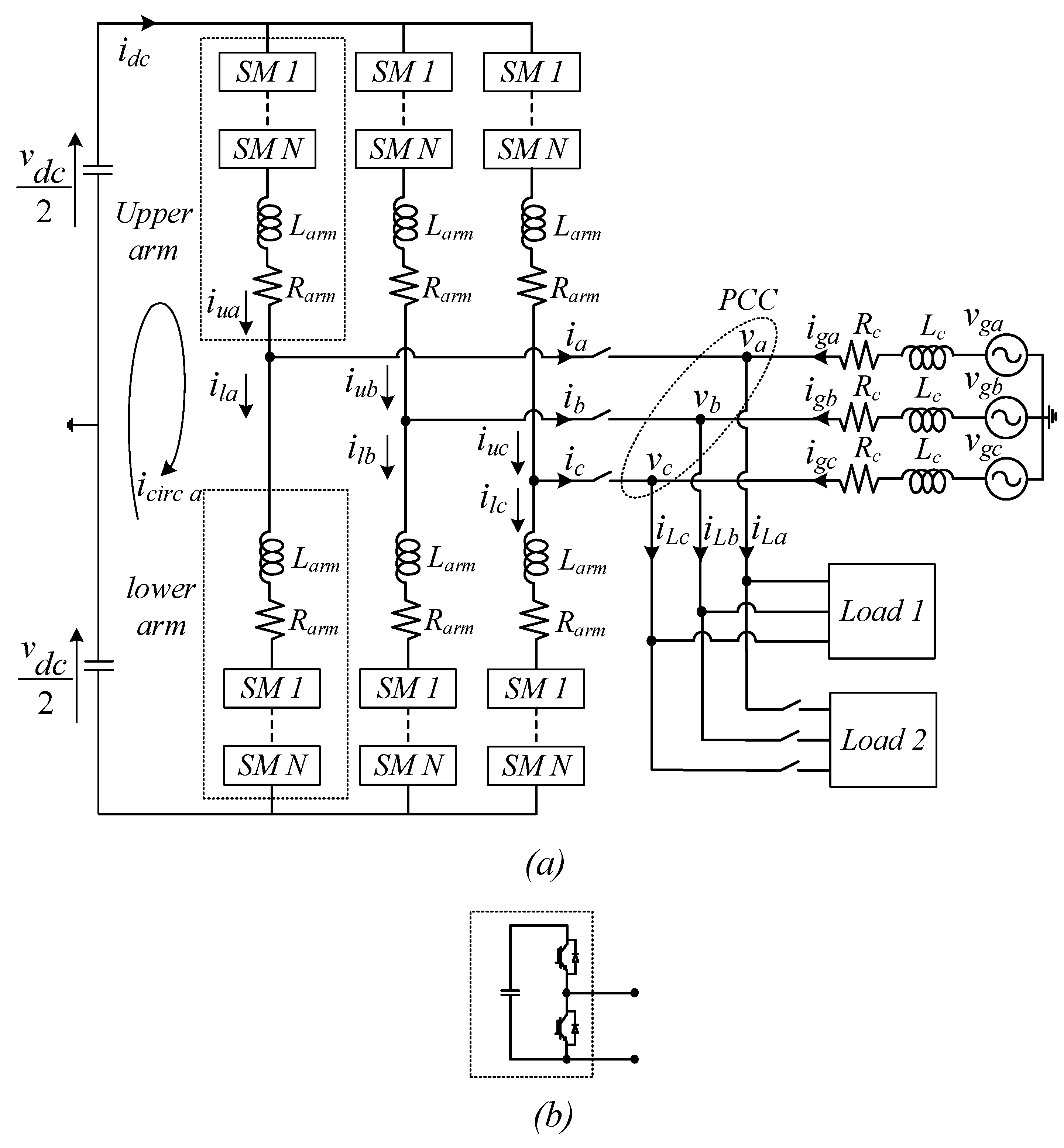
2. General Configuration and Dynamic Analysis of the Proposed Model

The most conventional configuration of a modern three-phase MMC is shown in Figure 1a. It should be noted that the improvement of grid imbalance studies is not considered as the purpose of the MMC utilization in this configuration and, therefore, the network structure is assumed as a strong grid. Herein, MMC is utilized as an efficient STATCOM interface between the energy sources and the power grid. Thus, it can well improve the overall network performance by mainly providing reactive power demands of the load. Moreover, considering the MMC superiorities, the proposed MMC-based STATCOM structure can be used to renovate conventional power networks.
Using voltage and current components at the point of common coupling (PCC) as well as the converter and grid parameters, the proposed controller is designed based on dq frame dynamic and steady-state modelling of the MMC-based STATCOM structure. In this regard, MMC is supposed to provide all reactive power demands of the load within the feasible power range since this power factor correction behavior of the MMC is considered as the first priority of the proposed controller. Moreover, the maximum stable operation region is evaluated. Based on that, the MMC can also provide maximum available active power demands of the load in order to reduce the load stress imposed on the power grid. Besides, a circulating current controller is also considered in order to improve converter operation using second harmonic current elimination, which also leads to a reduction in the capacitor voltage fluctuations as well.
As can be seen in Figure 1a, each phase leg is composed of two arms in which N SMs are connected in series along with one parasitic resistance Rarm and one arm inductor Larm. The SMs are commonly based on half-bridge structures, consisting of a DC capacitor and two insulated gate bipolar transistor (IGBT)/Diode switches as shown in Figure 1b. It should be noted that arm inductors are embedded in order to limit fault based or inherent harmonic components of each arm-current. Besides, Rarm stands for inductor inner resistance and converter losses and thus varies with operational conditions. Also, it should be noted that the grid model here is considered to be a 10 KV feeder.
According to Figure 1a, arm currents of each phase can be described as:
i u x = i c i r c x + i x 2
i l x = i c i r c x i x 2
where the circulating current (which is flowing between the DC link and each phase leg) is supposed to have DC and second harmonic components [30,31], while i x is considered as the sinusoidal current of phase x at the fundamental frequency.
On the other hand, the instant number of inserted SMs in each arm determines the arm voltage and thus directly affects the output voltage as well. In other words, each arm voltage is controlled through modulation index (n) which is defined as the ratio between sum capacitor voltages ( U c Σ ) and desired voltages of each arm ( U c ). Given that n varies from zero to one, we have:
{ U c u x = n u x U c u x Σ U c l x = n l x U c l x Σ
The control modulation indices and sum capacitor voltages are considered to include DC, fundamental, and second harmonic components. This is due to the presence of different harmonic components in both upper and lower arm currents which inevitably affects the SM capacitor voltages and thus should be considered in the control modulation indices as well. Therefore, these signals can be represented in dq0 frame as follows:
n u = ( 1 2 ) + ( m d 2 ) c o s ( ω t ) + ( m q 2 ) s i n ( ω t ) + ( m d 2 2 ) c o s ( 2 ω t ) + ( m q 2 2 ) s i n ( 2 ω t )
n l = ( 1 2 ) + ( m d 2 ) c o s ( ω t ) + ( m q 2 ) s i n ( ω t ) + ( m d 2 2 ) c o s ( 2 ω t ) + ( m q 2 2 ) s i n ( 2 ω t )
U c u Σ ( t ) = U c u m 0 Σ + U c u m 1 Σ cos ( ω t θ u ) + U c u m 2 Σ cos ( 2 ω t θ u 2 ) U c u 0 Σ + U c u d Σ + U c u q Σ + U c u d 2 Σ + U c u q 2 Σ
U c l Σ ( t ) = U c l m 0 Σ + U c l m 1 Σ cos ( ω t θ l ) + U c l m 2 Σ cos ( 2 ω t θ l 2 ) U c l 0 Σ + U c l d Σ + U c l q Σ + U c l d 2 Σ + U c l q 2 Σ
In addition, the dynamic equation describing energy storage capability of SM capacitors in each arm can be written as:
W c u , l Σ = 1 2 C N ( U c u , l Σ ) 2
Following that, the energy derivative is equal to the power injected into each arm. Therefore:
d W c u , l Σ d t = C N ( U c u , l Σ ) ( d U c u , l Σ d t ) = ( U c u , l ) ( i u , l )
Substituting U c u , l = n u , l U c u , l Σ , Equation (10) can be obtained as:
C N d U c u , l Σ d t = n u , l i u , l
Then, harmonic components of the upper arm current, modulation index, and sum capacitor voltage are considered based on Equations (1), (4), and (6) respectively. Thus, for the upper arm, Equation (10) can be rewritten in dq0 frame as follows:
C N d d t ( U c u 0 Σ + U c u d Σ c o s   ω t + U c u q Σ s i n   ω t + U c u d 2 Σ c o s   2 ω t + U c u q 2 Σ s i n   2 ω t ) = ( 1 2 + m d 2 c o s   ω t + m q 2 s i n   ω t + m d 2 2 c o s   2 ω t + m q 2 2 s i n   2 ω t ) ( i u 0 + i u d c o s   ω t + i u q s i n   ω t + i u d 2 c o s   2 ω t + i u q 2 s i n   2 ω t )
The next step would be applying the dq0 frame derivation term in the left-hand side as well as multiplying the two expressions in right-hand side of Equation (11). Representing different harmonic components of the product signal in different matrix rows leads to:
C N d d t [ U c u d Σ U c u q Σ U c u d 2 Σ U c u q 2 Σ U c u 0 Σ ] = C N [ 0 ω 0 0 0 ω 0 0 0 0 0 0 0 2 ω 0 0 0 2 ω 0 0 0 0 0 0 0 ] [ U c u d Σ U c u q Σ U c u d 2 Σ U c u q 2 Σ U c u 0 Σ ] + [ m d 2 i u 0 + 1 2 i u d m d 2 4 i u d m q 2 4 i u q m d 4 i u d 2 m q 4 i u q 2 m q 2 i u 0 + 1 2 i u q + m d 2 4 i u q m q 2 4 i u d + m q 4 i u d 2 m d 4 i u q 2 m d 4 i u d + m q 4 i u q m d 2 2 i u 0 + 1 2 i u d 2 m q 4 i u d m d 4 i u q m q 2 2 i u 0 + 1 2 i u q 2 1 2 i u 0 m d 4 i u d m q 4 i u q m d 2 4 i u d 2 m q 2 4 i u q 2 ]
On the other hand, v x is considered as the MMC output voltage at PCC. In this regard, applying KVL to the circuit structure of the proposed MMC-based STATCOM represented in Figure 1a yields to:
v d c 2 n u x U c u x Σ L a r m d i u x d t R a r m i u x = v x
According to Equations (4)–(7), dynamic state-space equations of the proposed model are derived in dq0 frame as:
L a r m d d t [ i u d i u q i u 0 ] = [ R a r m L a r m ω 0 L a r m ω R a r m 0 0 0 R a r m ] [ i u d i u q i u 0 ] [ v d v q 0 ] + [ 0 0 v d c 2 ] [ m d 2 U c u 0 Σ + 1 2 U c u d Σ m d 2 4 U c u d Σ m q 2 4 U c u q Σ m d 4 U c u d 2 Σ m q 4 U c u q 2 Σ m q 2 U c u 0 Σ + 1 2 U c u q Σ + m d 2 4 U c u q Σ m q 2 4 U c u d Σ + m q 4 U c u d 2 Σ m d 4 U c u q 2 Σ 1 2 U c u 0 Σ m d 4 U c u d Σ m q 4 U c u q Σ m d 2 4 U c u d 2 Σ m q 2 4 U c u q 2 Σ ]

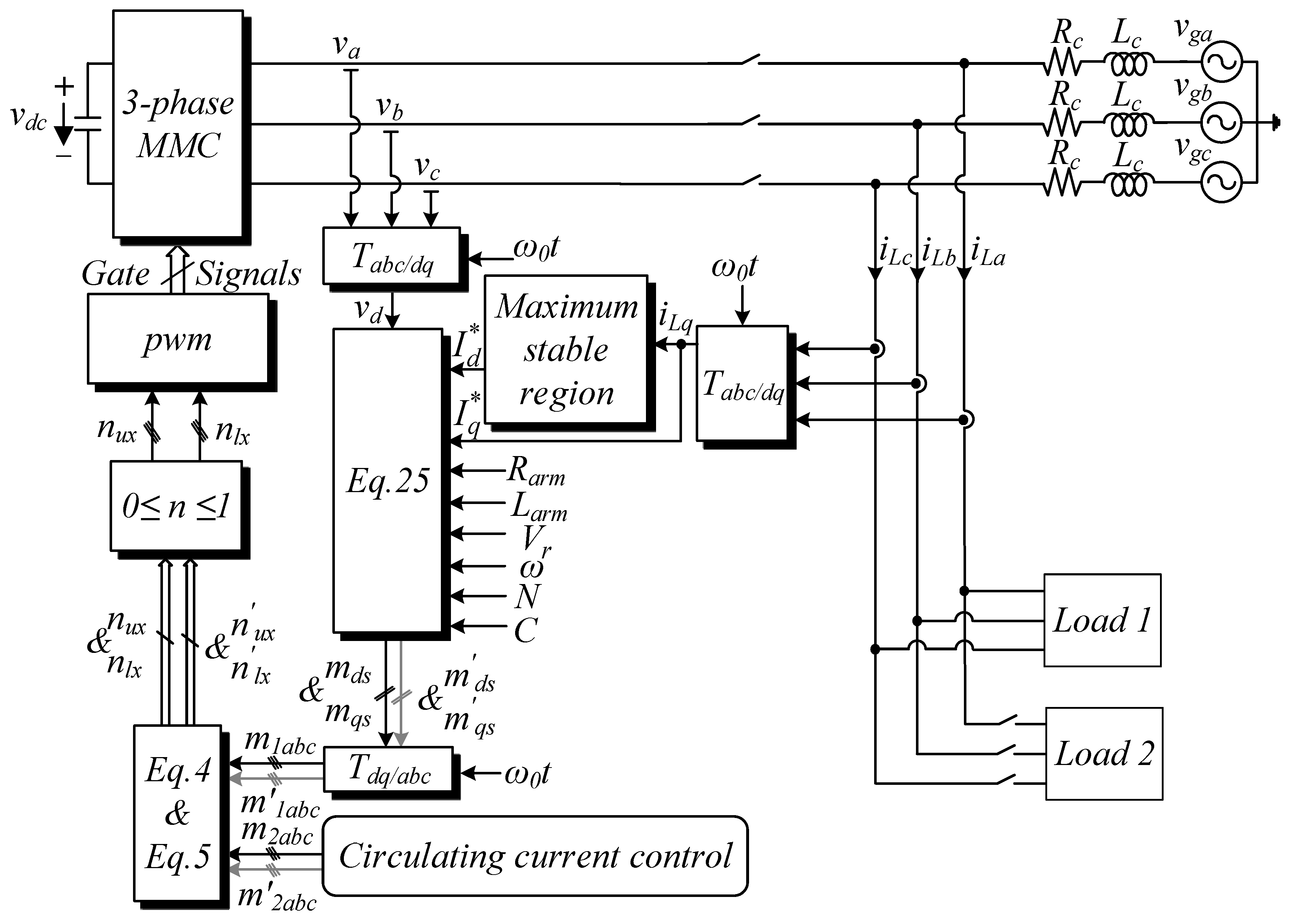
3. Steady-State Operation Analysis and Controller Design

In order to study the stable performance of the converter, dynamic equations of sum capacitor voltages are evaluated in the proposed model. Rewriting (12) in steady-state, all voltage derivatives are equated to zero while zero component of sum capacitor voltages ( U c u 0 Σ ) is replaced with the reference value of DC-link voltage ( V r ). Also, second harmonic components of the currents, as well as the control modulation indices ( m d 2 and m q 2 ), can be neglected due to the embedded circulating current control algorithm. Therefore, based on the last row of (12), i u 0 can be expressed as:
i u 0 = m d s 2 i u d + m q s 2 i u q
which then yields to:
U c u d Σ = N ( m q s 2 2 ) 4 C ω i u q
U c u q Σ = N ( m d s 2 2 ) 4 C ω i u d
U c u d 2 Σ = N m q s 8 C ω i u d N m d s 8 C ω i u q
U c u q 2 Σ = N m d s 8 C ω i u d N m q s 8 C ω i u q
On the other hand, Equation (14) should also be studied under stable operating mode in order to evaluate the steady-state modulation indices. Concerning this, the instantaneous arm currents are substituted with their reference values and the derivations are also considered in order to improve controller dynamics. Consequently:
d i u d d t = I a v u d = I a v d 2   , d i u q d t = I a v u q = I a v q 2
i u d = I u d = I d 2   ,   i u q = I u q = I q 2   ,   i u 0 = I 0
Finally, applying the abovementioned assumptions to Equation (14) yields to the steady-state expressions of the proposed model as follows:
[ L a r m 2 0 0 0 L a r m 2 0 m d s 4 L a r m m q s 4 L a r m 0 ] [ I a v d I a v q V r ] = [ V d V q 0 ] + [ R a r m 2 L a r m 2 ω + N ( 3 m q s 2 m d s 2 8 ) 64 C ω m d s 2 L a r m 2 ω N ( 3 m d s 2 m q s 2 8 ) 64 C ω R a r m 2 m q s 2 8 m d s C ω R a r m + 2 N m q s 32 C ω 8 m q s C ω R a r m 2 N m d s 32 C ω 0 ] [ I d I q V r ]
Last row of Equation (22) can be rewritten as:
m d s ( L a r m 4 I a v d + R a r m 4 A I d N 16 C ω I q ) = m q s ( L a r m 4 I a v q R a r m 4 B I q N 16 C ω I d )
As can be seen, constant values of A and B leads to a linear relation between modulation indices. Applying this to the first row of Equation (22), a quadratic equation in terms of m d s is obtained as:
( 3 N A 2 B 2 ) I q 64 C ω B 2 m d s 2 + V r 2 m d s = V d + L a r m 2 I a v d + R a r m 2 I d L a r m 2 ω I q + 1 8 C ω I q
Finally, m d s and m q s can be calculated by solving the above equation as follows:
{ m d s = 16 C ω B 2 V r ( 3 N A 2 B 2 ) I q ± V r 2 4 ( ( 3 N A 2 B 2 ) I q 16 C ω B 2 ) ( V d + L a r m 2 I a v d + R a r m 2 I d L a r m 2 ω I q + 1 8 C ω I q ) ( 3 N A 2 B 2 ) I q 32 C ω B 2 m q s = ( L a r m 4 I a v d + R a r m 4 I d N 16 C ω I q L a r m 4 I a v q R a r m 4 I q N 16 C ω I d ) m d s
In order to improve the proposed model performance, a circulating current control algorithm will be described in advance while the maximum available range of power transfer is also determined for the studied MMC-based STATCOM. The former eliminates the adverse effects of circulating currents on the model operation while the latter is used to achieve the best active and reactive power compensation in the MMC-based STATCOM structure.

3.1. Circulating Current Control

Although circulating currents have no effect on output quantities of the interfaced converter, different elimination algorithms are suggested in this field. These internal currents are originated from instantaneous voltage differences between each phase and the DC-link. The most prominent components of this current are DC and second harmonic. The DC part is responsible for the DC to AC power transfer while the second harmonic component increases arm currents and losses as well. In order to design an efficient controller based on second harmonic equations of the converter, KVL should be considered for each phase loop based on Figure 1a. Given that the phase sequence of transformation to the rotational frame at θ = 2 ω t is a-c-b, the aforementioned KVL can be expressed as:
L a r m d d t [ i u d 2 i u q 2 ] = [ R a r m 2 L a r m ω 2 L a r m ω R a r m ] [ i u d 2 i u q 2 ] [ m d 4 U c u d Σ + m q 4 U c u q Σ m d 2 2 U c u 0 Σ + 1 2 U c u d 2 Σ m q 4 U c u d Σ m d 4 U c u q Σ m q 2 2 U c u 0 Σ + 1 2 U c u q 2 Σ ]
Second harmonic current elimination can be accomplished using corresponding second harmonic components of modulation indices. Therefore, m d 2 and m q 2 are directly evaluated based on Equation (26) as follows:
m d 2 = 2 U c u 0 Σ [ L a r m d d t i u d 2 + R a r m i u d 2 2 L a r m ω i u q 2 m d 4 U c u d Σ + m q 4 U c u q Σ + 1 2 U c u d 2 Σ ]
m q 2 = 2 U c u 0 Σ [ L a r m d d t i u q 2 + R a r m i u q 2 + 2 L a r m ω i u d 2 m q 4 U c u d Σ m d 4 U c u q Σ   + 1 2 U c u q 2 Σ ]
The abovementioned equations can be utilized in order to design the appropriate controller. As demonstrated in Figure 2, PI controllers are included in order to eliminate the evaluated second harmonic components of modulation indices and thus minimize the second harmonic components of the currents.

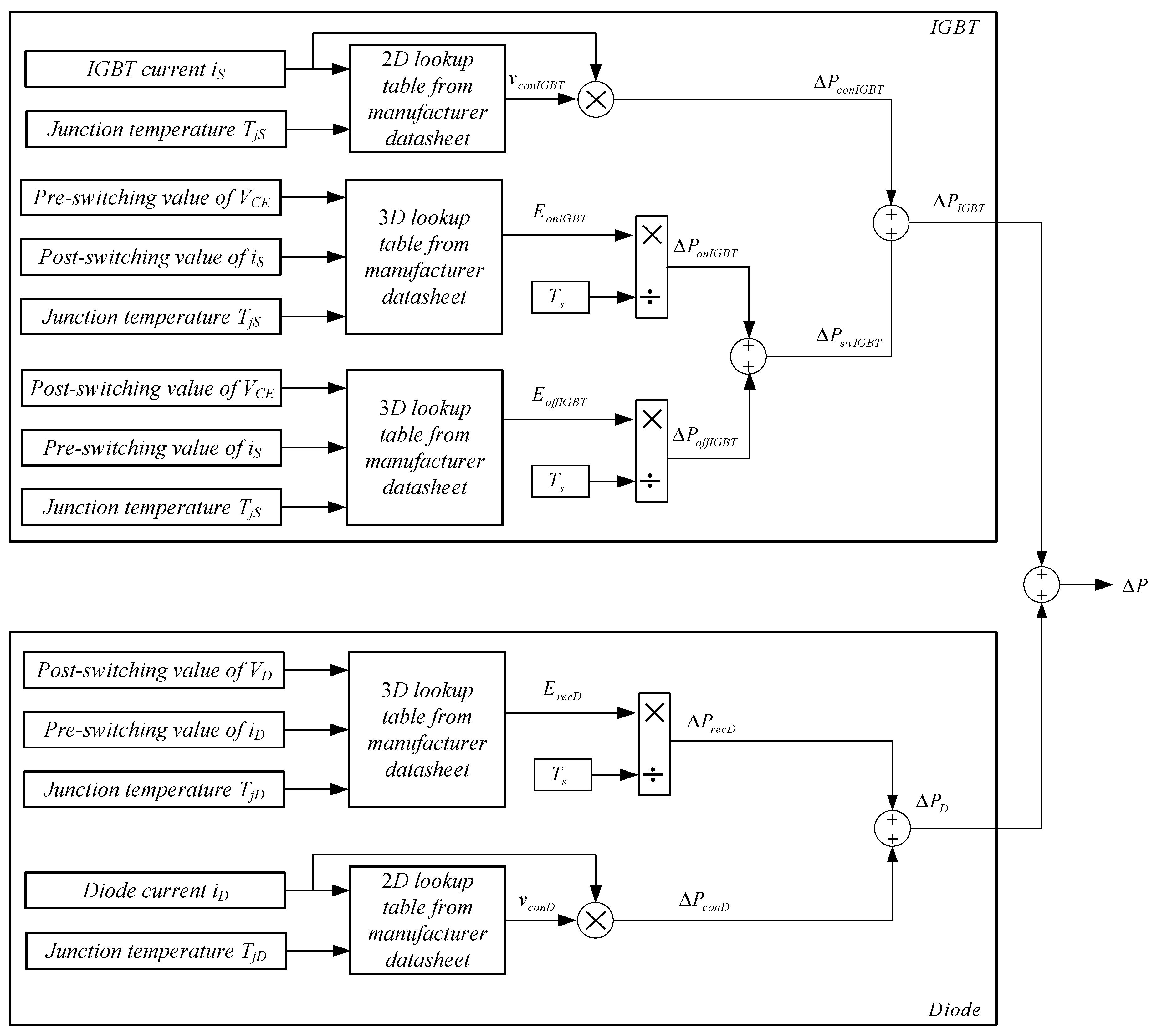
3.2. MMC Loss Evaluations

In this section the procedure for loss calculation of MMC is presented in order to evaluate the effect of the proposed circulating current control on semiconductor losses. In this regard, first the proper switch has been selected for this application. Then, converter losses have been calculated for the proposed MMC structure with and without circulating current control.
Figure 3 shows the block diagram for loss calculation in each IGBT/Diode switch structure. It should be noted that semiconductor losses can be divided into three parts: conduction losses, switching losses, and blocking losses. Since blocking losses are normally not considered, it can be concluded that total semiconductor losses are composed of conduction and switching losses. In this paper, the loss calculation is based on information extracted from manufacturer datasheet; more details are given in [32].
Conduction loss calculations for both IGBTs and diodes are achieved through multiplying the voltage across the semiconductor by the current passing through it as follows:
Δ P c o n I G B T / D = V c o n I G B T / D × i S / D ( t )
However, switching losses of IGBTs and diodes are calculated through different procedures. Considering IGBTs, switching losses are divided into turn-on and turn-off losses. These losses can be achieved based on turn-on and turn-off energy losses during turn-on and turn-off commutation times respectively. In this regard, first energy losses can be calculated as follows:
E o n I G B T = T T + t o n V C E ( t ) × i S ( t ) d t
E o f f I G B T = T T + t o f f V C E ( t ) × i S ( t ) d t
Then, the turn-on and turn-off switching losses can be achieved through dividing turn-on and turn-off energy losses by simulation time step as follows:
Δ P o n I G B T = E o n I G B T T s
Δ P o f f I G B T = E o f f I G B T T s
On the other hand, reverse recovery loss of diode is also achieved based on the reverse recovery energy losses during reverse recovery time of diode as follows:
E r e c D = T T + t r e c V D ( t ) × i D ( t ) d t
Δ P r e c D = E r e c D T s
Finally, the sum of all these calculated loss quantities gives the total loss amount in each IGBT/Diode switch. Considering all switches together, this method can be used in order to evaluate the beneficial effects of circulating current control on MMC loss reductions.

3.3. Maximum Stable Operation Range

Acting as STATCOM, MMC should provide the maximum available reactive power demand in order to improve the grid-side power factor. In consequence, the maximum stable power supply range should be determined based on different converter and energy source parameters.
Input DC power inserted to MMC would be equal to output AC power if the losses are neglected. Therefore,
v d c i d c = ( v d i d + v q i q )
On the other hand, applying KVL to Figure 1a results in the following dynamics:
v d = v g d + R c i g d + L c d i g d d t ω L c i g q
v q = v g q + R c i g q + L c d i g q d t + ω L c i g d
Given that i g d = i L d i d and i g q = i L q i q , we can substitute Equations (37) and (38) into (36), which leads to:
( i d + L c ( i a v d i a v L d ) R c i L d v g d 2 R c ) 2 + ( i q + L c ( i a v q i a v L q ) R c i L q v g q 2 R c ) 2 = ( ( L c ( i a v d i a v L d ) R c i L d v g d ) 2 + ( L c ( i a v q i a v L q ) R c i L q v g q ) 2 + 4 R c v d c i d c ) / ( 4 R c 2 )
Equation (39) has been developed based on converter power capacity equations represented in (36). Therefore, the equation represents current (and thus power) margins of the MMC in a stable operation mode based on converter and grid parameters. Note that these calculations study converter power capacity from the fundamental harmonic point of view.
On the other hand, considering the first row of Equation (26) in steady-state operating condition leads to:
m d 4 U c u d Σ m q 4 U c u q Σ 1 2 U c u d 2 Σ = 0
which then can be rewritten using Equations (16)–(18) as follows:
m d m q = I d I q
Replacing (23) in (41) gives:
I d I q = L a r m 4 I a v q + R a r m 4 I q + N 16 C ω I d L a r m 4 I a v d + R a r m 4 I d N 16 C ω I q
which can also be written as follows:
( I q + L a r m 2 R a r m I a v q ) 2 ( I d + L a r m 2 R a r m I a v d ) 2 = L a r m 2 4 R a r m 2 ( I a v q 2 I a v d 2 )
Equation (43) describes a hyperbolic while (39) is the equation of a circle with the centre of
( L c ( i a v d i a v L d ) R c i L d v g d 2 R c , L c ( i a v q i a v L q ) R c i L q v g q 2 R c )
and the radius measure of
( ( L c ( i a v d i a v L d ) R c i L d v g d ) 2 + ( L c ( i a v q i a v L q ) R c i L q v g q ) 2 + 4 R c v d c i d c ) / ( 4 R c 2 )
Drawing them together, the current and thus power flow can be estimated in order to guarantee MMC stability as STATCOM in the proposed model. Therefore, the stable operation range of the converter is demonstrated as the dashed area in Figure 4. It is clear that the stable operation can be obtained for current amounts which are inside the specified criteria since the margins are obtained based on converter power capacity.

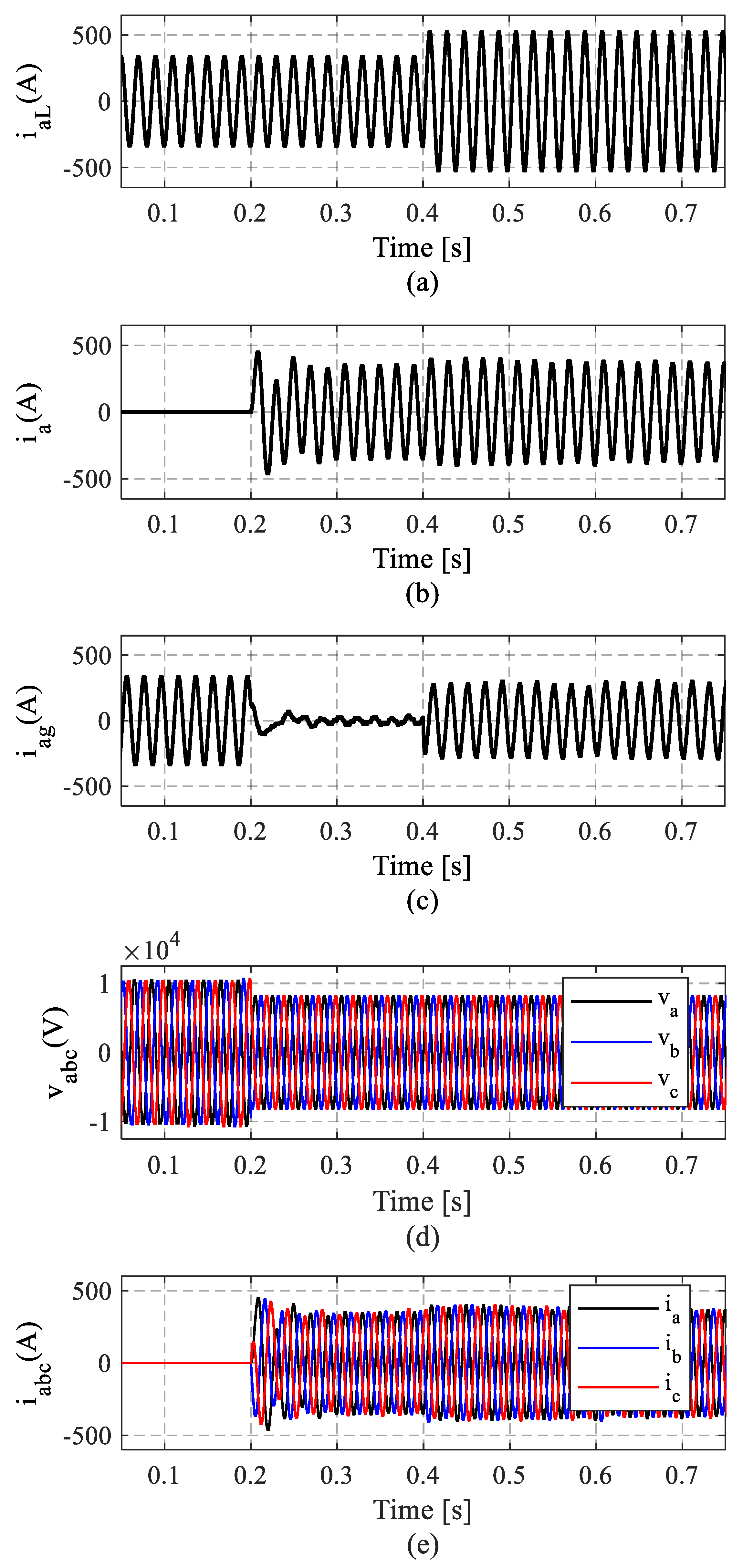
4. Results and Discussion

The detailed configuration of the MMC-based STATCOM and proposed control method shown in Figure 5 has been simulated in MATLAB/Simulink. The converter structure, as well as the proposed control method, have been simulated using various blocks of the Simulink library. The main blocks used in the simulation of the grid-connected MMC structure and the measurements have been derived from the following section of the MATLAB/Simulink library:
"Simscape/ Power Systems/ Specialized Technology/ Fundamental Blocks".
Besides, the values of different circuit components and operational conditions applied to simulations are listed in Table 1.
In this paper, the MMC has been considered as a STATCOM interface between DC-link and the grid. Considering the maximum stable operation range of the converter, MMC is supposed to provide all reactive power demands as well as maximum available active power demands of the load within the feasible power range. Therefore, MMC will be able to efficiently provide the power factor correction behavior of a STATCOM interface. Moreover, a circulating current control algorithm is also considered in the proposed control method. The proposed controller is expected to improve MMC performance by eliminating the second harmonic components of currents, which also leads to a reduction in the capacitor voltage fluctuations.
In order to validate the efficient performance of the proposed control and switching method, four different simulation time intervals have been discussed separately. At the first time interval of simulation, the MMC has been disconnected, leaving load demands to the network. As can be seen in Figure 6a–c, the load current is initially provided by the grid, while the disconnected converter structure delivers maximum voltage during this no-load period (demonstrated in Figure 6d). At the second time interval, the energy source is connected to the grid through PCC at 0.2 s. Figure 6c shows that the grid current reaches to the minimum value as the load current is supplied by energy source through the efficient MMC connection (see Figure 6a,b respectively). This feature has a noticeable impact on voltage stress reduction of the grid, especially in peak demand times, since MMC can help the grid in providing load demands.
During the third time interval, active and reactive power demands of the load are increased due to the addition of the second load at 0.4 s. As can be seen in Figure 6, MMC supplies maximum available load based on the stability margin and the rest is accomplished by the grid. The most important studied capability of the proposed model at this time period is the priority of reactive power compensation, which will be discussed further in detail.
It should be noted that the proposed controller can provide stable operation during all these dynamic changes. Thus, the output voltages and currents are stable as shown in Figure 6d,e respectively.
In order to verify MMC capabilities as STATCOM, reactive power compensation can be accurately discussed based on a more detailed analysis of current components. As demonstrated in Figure 5, the maximum available power capacity of MMC based on converter and grid parameters have been considered in the simulation process as follows:
Considering the maximum available power capacity of the converter, the MMC supplies all reactive power demand of the load within the feasible power range. This power factor correction behavior of the converter is considered as a priority in the proposed control method of this MMC-based STATCOM structure. Therefore, with the assumption of converter power capacity being way more than load reactive power demand, it is considered that I q = i l q (which means that load reactive power demand is completely supplied by the MMC-based STATCOM structure). On the other hand, the excess amount of power remaining from total power capacity of the converter is utilized to provide the active power demand of the load. This way the grid provides less active power for the load and the load stress imposed on power grid can be reduced. In this regard, active power reference of the converter is modified based on maximum stable operation range of the converter. The desired range is specified by (39) and (43) in which the converter and the grid parameters, as well as the reactive current components, have been modified.
Figure 7 illustrates reactive current components of the simulated system in dq0 frame. As mentioned before, load reactive power demands (even after load increment at 0.4 s) are considered to be less than the converter’s maximum power transfer capability. At the same time, providing reactive power demands of the load is considered as the first priority of the proposed MMC-based STATCOM model. Therefore, it can be seen that after MMC connection at 0.2 s all reactive current demands of the load are compensated through the energy source (see Figure 7a,b respectively). This yields to an almost zero reactive current flow in the grid side after the MMC connection, which is clearly shown in Figure 7.
On the other hand, active current components of the simulated system in dq0 frame are demonstrated in Figure 8. As it can be seen, grid current supplies active power demands of the load before 0.2 s as the energy source is not connected yet. During the time interval of 0.2 < t < 0.4 s the energy source provides maximum established active power, keeping the grid current at the lowest level. As the load demands are increased after 0.4 s, converter current waveform remains almost constant, which can be seen in Figure 8a,b respectively. This is due to the active power margin specification of the MMC, which depends on the maximum available power left after providing all load reactive power demands. Therefore, the grid current increment after 0.4 s is justifiable due to the abovementioned explanations and it is less worrying since the grid power factor is not decayed.
The power factor correction capability of the proposed model can be seen in Figure 9. An obvious phase difference between the grid voltages and currents can be detected before 0.2 s when the MMC-based STATCOM structure is not connected yet and the load active and reactive power demands are completely provided by the grid. During the time interval of 0.2 < t < 0.4 s, MMC provides all active and reactive power demands of the load as it can be completely covered within the converter stable operation range. Consequently, the grid current is kept at its lowest amount during this time interval. Following that, with an increase in load active and reactive power demands after 0.4 s, the MMC provides all reactive as well as the most available active power demands of the load within the stable operation range. Therefore, providing the rest of load active power demands will be the only responsibility of the grid at this time. It is obvious that the reactive power compensating method is working properly since the phase differences between the grid voltages and currents are reduced effectively.
As another contribution of this paper, circulating current control was applied during the 4th interval of the simulation time. As can be seen in Figure 10a, applying the proposed circulating current control after 0.6 sec can lead to a 90% reduction in the second harmonic component of arm current. This is while most recent studies of the same field have been unable to provide such mitigations in harmonic components of arm currents. For example, reference [33] proposes a unified on-line calculation scheme by using the instantaneous information of MMC in order to achieve different circulating current injection targets under different conditions. In this regard, four circulating current control targets have been considered. The comparisons between the obtained circulating current waves and the uncontrolled one show that the largest decrease in the circulating current value can be achieved under the first scenario and with the amount of 50%. As another example, reference [34] employs a feedback linearization-based current control strategy in order to regulate the output and inner differential currents of the MMC. Furthermore, the conventional cascaded controller is also considered where the differential current is only regulated by PI controller. A comparison of the obtained results shows that the harmonics in the differential current are reduced from 25% to 3.22% with the aid of the feedback linearization method. This is while the proposed circulating current control in this paper leads to a final 0.5% circulating current remaining in the total arm current, and therefore, shows an effective improvement in circulating current mitigation over the previous methods represented in various recent studies. It should also be noted that the additional second harmonic component of modulation indices generated by the controller can improve arm current adjustments as well as reduce the capacitor voltage fluctuations. The abovementioned results are demonstrated in Figure 10b,c respectively. It should be noted that circulating currents are considered as interior quantities. Therefore, the applied control algorithm has no direct effect on converter outer dynamic performances which is clearly reflected in Figure 6b,d,e.
In order to evaluate the beneficial effects of the proposed circulating current control on MMC loss reductions, several studies have been accomplished. In this regard, MMC loss calculations have been performed considering a fixed load active power demand of 0.5 MW as well as various load reactive power demands. Figure 11 demonstrates the MMC losses, with and without circulating current control for five different values of reactive power. As it can be observed from the figure, the losses are decreased by more than 10% (and up to 16% in the first two reactive power amounts) due to mitigation of circulating current. This is while most recent studies in this field are suggesting less than 10% reductions in converter losses, using various second harmonic current control approaches [35,36]. Therefore, MMC loss evaluations provided in Figure 11 confirm that the proposed method can effectively improve converter operation in power loss terms, as well.

5. Conclusions

This paper presented a dynamic model of MMC in STATCOM operating mode. Detailed harmonic evaluations were performed in dq0 frame in order to provide an efficient control method. Based on steady-state equations, modulation indices have been obtained so that the stable connection between the energy source and the power grid was securely established. Circulating current control was provided through second harmonic component additions to the overall modulation process. As a novelty of this paper, the abovementioned method helped improve capacitor voltage regulations, as well as arm current harmonic characteristics and losses. Also, the maximum stability margin of the converter was developed based on dynamic studies, which is considered as another contribution of this paper. Reactive power compensation is considered as a priority in the proposed MMC-based STATCOM performance. Thus, controller design was focused on the maximum reactive power supply, leaving an upper limit for the active power coverage ability of the converter based on the modified maximum stable operation range. It has been shown that MMC can efficiently provide reactive power demands of the load, resulting in grid power factor correction. It should be noted that since the improvement of the grid imbalance studies is not considered as the purpose of MMC utilization in this configuration, the proposed control method becomes vulnerable if grid voltage imbalance situations occur. The main reason of this, which can be addressed in future work, is that the appeared negative sequence components in grid imbalance studies are not considered in the proposed control method. Despite this limitation, advantageous MMC superiorities lead to various applications where the proposed MMC-based STATCOM structure can be used to renovate conventional power networks.

Author Contributions

Formal analysis, E.A.; Investigation, K.R.; Methodology, J.A.; Supervision, E.P.; Visualization, J.P.S.C.; Writing—original draft, F.S.; Writing—review & editing, E.A. and E.M.G.R.

Funding

This research received no external funding.

Conflicts of Interest

The authors declare no conflict of interest.

Nomenclature

Indices
xa, b, c
u, lupper and lower arm
Variables
i u x , i l x upper and lower arm currents in abc frame
i c i r c x circulating current in abc frame
i x converter output current in abc frame
i L x load current in abc frame
U c u x , U c l x upper and lower arm desired voltages in abc frame
n u x , n l x upper and lower arm modulation indices in abc frame
U c u x Σ , U c l x Σ upper and lower arm sum capacitor voltages in abc frame
m 1 x fundamental frequency component of modulation indices in abc frame
m 2 x second harmonic component of modulation indices in dq0 frame
m d , m q fundamental frequency component of modulation indices in dq0 frame
m d 2 , m q 2 second harmonic component of modulation indices in dq0 frame
U c u m 0 Σ , U c l m 0 Σ DC components of upper and lower arm sum capacitor voltages in abc frame
U c u m 1 Σ , U c l m 1 Σ fundamental frequency components of upper and lower arm sum capacitor voltages in abc frame
U c u m 2 Σ , U c l m 2 Σ second harmonic components of upper and lower arm sum capacitor voltages in abc frame
ωangular frequency
ω0reference angular frequency
ttime
θ u , θ l phase angle of the fundamental frequency components of upper and lower arm sum capacitor voltages in abc frame
θ u 2 , θ l 2 phase angle of the second harmonic frequency components of upper and lower arm sum capacitor voltages in abc frame
U c u 0 Σ , U c l 0 Σ zero component of upper and lower arm sum capacitor voltages in dq0 frame
U c u d Σ , U c u q Σ fundamental frequency components of upper arm sum capacitor voltage in dq0 frame
U c l d Σ , U c l q Σ fundamental frequency components of lower arm sum capacitor voltage in dq0 frame
U c u d 2 Σ , U c u q 2 Σ second harmonic frequency components of upper arm sum capacitor voltage in dq0 frame
U c l d 2 Σ , U c l q 2 Σ second harmonic frequency components of lower arm sum capacitor voltage in dq0 frame
W c u , l Σ total energy stored in SM capacitors of each upper and lower arm
i u 0 zero component of upper arm current in dq0 frame
i u d , i u q fundamental frequency components of upper arm current in dq0 frame
i u d 2 , i u q 2 second harmonic components of upper arm current in dq0 frame
v d c DC-link voltage
V r reference value of DC-link voltage
i d c DC-link current
v x MMC output voltage at PCC in abc frame
v g x phase voltage of the grid in abc frame
v d , v q fundamental frequency components of MMC output voltage at PCC in dq0 frame
v g d , v q g fundamental frequency components of grid voltage at PCC in dq0 frame
i d , i q fundamental frequency components of MMC output current in dq0 frame
i g d , i g q fundamental frequency components of grid current in dq0 frame
i L d , i L q fundamental frequency components of load current in dq0 frame
i a v d , i a v q fundamental frequency components of average MMC output current in dq0 frame
i a v L d , i a v L q fundamental frequency components of average load current in dq0 frame
m d s , m q s steady-state fundamental frequency components of modulation indices in dq0 frame
m d 2 s , m q 2 s steady-state second harmonic frequency components of modulation indices in dq0 frame
I a v u d , I a v u q reference values of average upper arm currents in dq0 frame
I a v d , I a v q reference values of average MMC output currents in dq0 frame
I u d , I u q reference values of instantaneous upper arm currents in dq0 frame
I d , I q reference values of MMC output currents in dq0 frame
I 0 reference value of upper arm zero component current in dq0 frame
V d , V q reference value of MMC output voltages in dq0 frame
Δ P total losses in each IGBT/diode switch
Δ P c o n I G B T / D conduction loss for IGBT/diode
V c o n I G B T / D voltage across IGBT/diode during conduction
i S / D current passing through IGBT/diode during conduction
Δ P I G B T total losses of IGBT
Δ P s w I G B T switching losses in IGBTs
Δ P o n I G B T turn-on switching losses of IGBTs
Δ P o f f I G B T turn-off switching losses of IGBTs
E o n I G B T turn-on energy losses of IGBTs
E o f f I G B T turn-off energy losses of IGBTs
t o n turn-on commutation time
t o f f turn-off commutation time
V C E voltage across IGBT
V D voltage across diode
T j S / D junction temperature in IGBT and diode
T s simulation time step
Δ P D total diode losses
Δ P r e c D reverse recovery loss of diode
E r e c D reverse recovery energy loss of diode
t r e c reverse recovery time of diode
Parameters
CSM capacitance
Ntotal number of SMs per arm
Rarmarm equivalent resistance
Larmarm inductance
Rcac system resistance
Lcac system inductance
Abbreviation
MMCmodular multilevel converter
STATCOMstatic synchronous compensator
DGdistributed generation
HVDChigh voltage direct current
THDtotal harmonic distortion
PFpower factor
FACTSflexible AC transmission system
PIproportional integral
SMsub-modules
PCCpoint of common coupling
KVLKirchhoff’s voltage law
IGBTinsulated gate bipolar transistor

References

  1. Ochoa, L.F.; Harrison, G.P. Minimizing energy losses: Optimal accommodation and smart operation of renewable distributed generation. IEEE Trans. Power Syst. 2010, 26, 198–205. [Google Scholar] [CrossRef]
  2. Shaaban, M.F.; Atwa, Y.M.; El-Saadany, E.F. DG allocation for benefit maximization in distribution networks. IEEE Trans. Power Syst. 2012, 28, 639–649. [Google Scholar] [CrossRef]
  3. Debnath, S.; Qin, J.; Bahrani, B.; Saeedifard, M.; Barbosa, P. Operation, control, and applications of the modular multilevel converter: A review. IEEE Trans. Power Electron. 2014, 30, 37–53. [Google Scholar] [CrossRef]
  4. Sahoo, A.K.; Otero-De-Leon, R.; Mohan, N. Review of modular multilevel converters for teaching a graduate-level course of power electronics in power systems. In Proceedings of the 2013 North American Power Symposium (NAPS), Manhattan, KS, USA, 22–24 September 2013; pp. 1–6. [Google Scholar]
  5. Nami, A.; Liang, J.; Dijkhuizen, F.; Demetriades, G.D. Modular multilevel converters for HVDC applications: Review on converter cells and functionalities. IEEE Trans. Power Electron. 2014, 30, 18–36. [Google Scholar] [CrossRef]
  6. Franquelo, L.G.; Rodriguez, J.; Leon, J.I.; Kouro, S.; Portillo, R.; Prats, M.A. The age of multilevel converters arrives. IEEE Ind. Electron. Mag. 2008, 2, 28–39. [Google Scholar] [CrossRef] [Green Version]
  7. Kouro, S.; Malinowski, M.; Gopakumar, K.; Pou, J.; Franquelo, L.G.; Wu, B.; Rodriguez, J.; Pérez, M.A.; Leon, J.I. Recent advances and industrial applications of multilevel converters. IEEE Trans. Ind. Electron. 2010, 57, 2553–2580. [Google Scholar] [CrossRef]
  8. Lawan, A.U.; Abbas, H.; Khor, J.G.; Karim, A.A. Dynamic performance improvement of MMC inverter with STATCOM capability interfacing PMSG wind turbines with grid. In Proceedings of the 2015 IEEE Conference on Energy Conversion (CENCON), Johor Bahru, Malaysia, 19–20 October 2015; pp. 492–497. [Google Scholar]
  9. Lesnicar, A.; Marquardt, R. An innovative modular multilevel converter topology suitable for a wide power range. In Proceedings of the 2003 IEEE Bologna Power Tech Conference Proceedings, Bologna, Italy, 23–26 June 2003. [Google Scholar]
  10. Liu, Z.; Hu, X.; Liao, Y. Vehicle-Grid System Stability Analysis Based on Norm Criterion and Suppression of Low-Frequency Oscillation With MMC-STATCOM. IEEE Trans. Transp. Electr. 2018, 4, 757–766. [Google Scholar] [CrossRef]
  11. Farias, J.V.M.; Cupertino, A.F.; Pereira, H.A.; Junior, S.I.S.; Teodorescu, R. On the redundancy strategies of modular multilevel converters. IEEE Trans. Power Deliv. 2017, 33, 851–860. [Google Scholar] [CrossRef]
  12. Yue, Y.; Ma, F.; Luo, A.; Xu, Q.; Xie, L. A circulating current suppressing method of MMC based STATCOM for negative-sequence compensation. In Proceedings of the 2016 IEEE 8th International Power Electronics and Motion Control Conference (IPEMC-ECCE Asia), Hefei, China, 22–26 May 2016. [Google Scholar]
  13. Muñoz, J.A.; Espinoza, J.R.; Baier, C.R.; Morán, L.A.; Guzmán, J.I.; Cárdenas, V.M. Decoupled and modular harmonic compensation for multilevel STATCOMs. IEEE Trans. Ind. Electr. 2013, 61, 2743–2753. [Google Scholar] [CrossRef]
  14. Zhu, J.; Li, L.; Pan, M. Study of a novel STATCOM based on modular multilevel inverter. In Proceedings of the IECON 2012-38th Annual Conference on IEEE Industrial Electronics Society, Montreal, QC, Canada, 25–28 October 2012; pp. 1428–1432. [Google Scholar]
  15. Zhang, W.; Gao, Q.; Su, B.; Jin, M.; Xu, D.; Liu, J. Research on the control strategy of STATCOM based on modular multilevel converter. In Proceedings of the 2014 International Power Electronics Conference (IPEC-Hiroshima 2014-ECCE ASIA), Hiroshima, Japan, 18–21 May 2014. [Google Scholar]
  16. Vivas, J.H.; Bergna, G.; Boyra, M. Comparison of multilevel converter-based STATCOMs. In Proceedings of the 2011 14th European Conference on Power Electronics and Applications, Birmingham, UK, 30 August–1 September 2011. [Google Scholar]
  17. Nwobu, C.J.; Efika, I.B.; Oghorada, O.J.K.; Zhang, L. A modular multilevel flying capacitor converter-based STATCOM for reactive power control in distribution systems. In Proceedings of the 2015 17th European Conference on Power Electronics and Applications (EPE’15 ECCE-Europe), Geneva, Switzerland, 8–10 September 2015. [Google Scholar]
  18. Liu, X.; Lv, J.; Gao, C.; Chen, Z.; Chen, S. A novel STATCOM based on diode-clamped modular multilevel converters. IEEE Trans. Power Electr. 2016, 32, 5964–5977. [Google Scholar] [CrossRef]
  19. Yang, X.; Li, J.; Fan, W.; Wang, X.; Zheng, T.Q. Research on modular multilevel converter based STATCOM. In Proceedings of the 2011 6th IEEE Conference on Industrial Electronics and Applications, Beijing, China, 21–23 June 2011; pp. 2569–2574. [Google Scholar]
  20. Pereira, H.A.; Haddioui, M.R.; De Oliveira, L.O.; Mathe, L.; Bongiorno, M.; Teodorescu, R. Circulating current suppression strategies for D-STATCOM based on modular Multilevel Converters. In Proceedings of the 2015 IEEE 13th Brazilian Power Electronics Conference and 1st Southern Power Electronics Conference (COBEP/SPEC), Fortaleza, Brazil, 29 November–2 December 2015; pp. 1–6. [Google Scholar]
  21. Nieves, M.; Maza, J.; Mauricio, J.; Teodorescu, R.; Bongiorno, M.; Rodriguez, P. Enhanced control strategy for MMC-based STATCOM for unbalanced load compensation. In Proceedings of the 2014 16th European Conference on Power Electronics and Applications, Lappeenranta, Finland, 26–28 August 2014; pp. 1–10. [Google Scholar]
  22. António-Ferreira, A.; Gomis-Bellmunt, O.; Teixidó, M. HVDC-based modular multilevel converter in the statcom operation mode. In Proceedings of the 2016 18th European Conference on Power Electronics and Applications (EPE’16 ECCE Europe), Karlsruhe, Germany, 5–9 September 2016; pp. 1–10. [Google Scholar]
  23. Liu, L.; Li, H.; Xue, Y.; Liu, W. Decoupled active and reactive power control for large-scale grid-connected photovoltaic systems using cascaded modular multilevel converters. IEEE Trans. Power Electr. 2014, 30, 176–187. [Google Scholar]
  24. Mehrasa, M.; Pouresmaeil, E.; Zabihi, S.; Catalao, J.P.S. Dynamic model, control and stability analysis of MMC in HVDC transmission systems. IEEE Trans. Power Deliv. 2016, 32, 1471–1482. [Google Scholar] [CrossRef]
  25. Mehrasa, M.; Pouresmaeil, E.; Zabihi, S.; Vechiu, I.; Catalão, J.P.S. A multi-loop control technique for the stable operation of modular multilevel converters in HVDC transmission systems. Int. J. Electr. Power Energy Syst. 2018, 96, 194–207. [Google Scholar] [CrossRef]
  26. Xu, C.; Dai, K.; Kang, Y.; Liu, C. Characteristic analysis and experimental verification of a novel capacitor voltage control strategy for three-phase MMC-DSTATCOM. In Proceedings of the 2015 IEEE Applied Power Electronics Conference and Exposition (APEC), Charlotte, NC, USA, 15–19 March 2015; pp. 1528–1533. [Google Scholar]
  27. Cupertino, A.F.; Farias, J.V.M.; Pereira, H.A.; Seleme, S.I.; Teodorescu, R. Comparison of dscc and sdbc modular multilevel converters for statcom application during negative sequence compensation. IEEE Trans. Ind. Electr. 2019, 66, 2302–2312. [Google Scholar] [CrossRef]
  28. Luo, F.; Wang, J.; Li, Z.; Duan, Q.; Lv, Z.; Ji, Z.; Gu, W.; Wu, Z. A circuit-oriented average-value model of modular multilevel converter based on sub-module modelling method. In Proceedings of the 2017 12th IEEE Conference on Industrial Electronics and Applications (ICIEA), Siem Reap, Cambodia, 18–20 June 2017; pp. 7–12. [Google Scholar]
  29. Mehrasa, M.; Pouresmaeil, E.; Taheri, S.; Vechiu, I.; Catalão, J.P.S. Novel control strategy for modular multilevel converters based on differential flatness theory. IEEE J. Emerg. Sel. Top. Power Electr. 2018, 6, 888–897. [Google Scholar] [CrossRef]
  30. Sun, Y.; Teixeira, C.A.; Holmes, D.G.; McGrath, B.P.; Zhao, J. Low-order circulating current suppression of PWM-based modular multilevel converters using DC-link voltage compensation. IEEE Trans. Power Electr. 2017, 33, 210–225. [Google Scholar] [CrossRef]
  31. Yang, S.; Wang, P.; Tang, Y.; Zagrodnik, M.; Hu, X.; Tseng, K.J. Circulating current suppression in modular multilevel converters with even-harmonic repetitive control. IEEE Trans. Ind. Appl. 2017, 54, 298–309. [Google Scholar] [CrossRef]
  32. Adabi, M.E.; Martinez-Velasco, J.A. MMC-based solid-state transformer model including semiconductor losses. Electr. Eng. 2018, 100, 1613–1630. [Google Scholar] [CrossRef]
  33. Wang, J.; Han, X.; Ma, H.; Bai, Z. Analysis and injection control of circulating current for modular multilevel converters. IEEE Trans. Ind. Electr. 2019, 66, 2280–2290. [Google Scholar] [CrossRef]
  34. Yang, S.; Wang, P.; Tang, Y. Feedback linearization-based current control strategy for modular multilevel converters. IEEE Trans. Power Electr. 2018, 33, 161–174. [Google Scholar] [CrossRef]
  35. Xiang, M.; Hu, J.; He, Z. Loss reduction analysis and control of AC voltage-boosted FBSM MMC by injecting second harmonic circulating current. J. Eng. 2018, 2019, 2328–2331. [Google Scholar] [CrossRef]
  36. Yang, L.; Li, Y.; Li, Z.; Wang, P.; Xu, S.; Gou, R. Loss optimization of MMC by second-order harmonic circulating current injection. IEEE Trans. Power Electr. 2018, 33, 5739–5753. [Google Scholar] [CrossRef]
Figure 1. General schematic of a modular multilevel converter (MMC)-based static synchronous compensator (STATCOM): (a) Circuit structure; (b) Sub-module (SM) configuration.
Electronics 08 01264 g001
Figure 2. Circulating current control algorithm.
Electronics 08 01264 g002
Figure 3. Loss calculation procedure for each insulated gate bipolar transistor (IGBT)/Diode switch.
Electronics 08 01264 g003
Figure 4. Stable operation region (hatched) for MMCs in STATCOM operating mode.
Electronics 08 01264 g004
Figure 5. General configuration of the proposed MMC-based STATCOM controller.
Electronics 08 01264 g005
Figure 6. Simulated waveforms of the MMC-based STATCOM structure: (a) Phase-a waveform of load current; (b) Phase-a waveform of converter output current; (c) Phase-a waveform of grid current; (d) Output voltages of MMC; and (e) Output currents of MMC.
Electronics 08 01264 g006
Figure 7. Reactive current components of the STATCOM model: (a) q component of load current; (b) q component of MMC current; and (c) q component of grid current.
Electronics 08 01264 g007
Figure 8. Active current components of the STATCOM model: (a) d component of load current; (b) d component of MMC current; and (c) d component of grid current.
Electronics 08 01264 g008
Figure 9. Grid voltage and current of phase-a before and after reactive power compensation.
Electronics 08 01264 g009
Figure 10. Simulated waveforms of the MMC using circulating current control: (a) Second harmonic component of the circulating current; (b) Upper arm current of phase-a; and (c) Upper arm SM capacitor voltages of phase-a.
Electronics 08 01264 g010
Figure 11. MMC losses with and without circulating current control.
Electronics 08 01264 g011
Table 1. MMC parameters and operational conditions applied to simulations.
ItemsValues
AC system voltage V g (L-L,rms)10 KV
AC system inductance Lc0.5 mH
AC system resistance Rc1 mΩ
DC bus voltage Vr20 KV
number of SMs per arm N20
SM capacitance C10,000 μF
arm inductance Larm40 mH
arm equivalent resistance Rarm1.5 Ω
SM capacitor voltage Vcsm1 KV
carrier frequency fsw5 KHz
simulation time step Ts83.3 × 10−6 s
Load1 active power Pref10.5 MW
Load1 reactive power Qref14 MVar
Load2 active power Pref23.5 MW
Load2 reactive power Qref20.8 MVar

