A Wearable Closed-Loop Insulin Delivery System Based on Low-Power SoCs


Electronics Department, University of Alcala, Alcala de Henares, Madrid 28805, Spain
*
Author to whom correspondence should be addressed.
Electronics 2019, 8(6), 612; https://0-doi-org.brum.beds.ac.uk/10.3390/electronics8060612
Submission received: 9 May 2019
/
Revised: 25 May 2019
/
Accepted: 29 May 2019
/
Published: 31 May 2019
(This article belongs to the Special Issue Low-power Wearable Healthcare Sensors)
Abstract
:The number of patients living with diabetes has increased significantly in recent years due to several factors. Many of these patients are choosing to use insulin pumps for their treatment, artificial systems that administer their insulin and consist of a glucometer and an automatic insulin supply working in an open loop. Currently, only a few closed-loop insulin delivery devices are commercially available. The most widespread systems among patients are what have been called the “Do-It-Yourself Hybrid Closed-Loop systems.” These systems require the use of platforms with high computing power. In this paper, we will present a novel wearable system for insulin delivery that reduces the energy and computing consumption of the platform without affecting the computation requirements. Patients’ information is obtained from a commercial continuous glucose sensor and a commercial insulin pump operating in a conventional manner. An ad-hoc embedded system will connect with the pump and the sensor to collect the glucose data and process it. That connection is accomplished through a radiofrequency channel that provides a suitable system for the patient. Thus, this system does not require to be connected to any other processor, which increases the overall stability. Using parameters configured by the patient, the control system will make automatic adjustments in the basal insulin infusion thereby bringing the patient’s glycaemia to the target set by a doctor’s prescription. The results obtained will be satisfactory as long as the configured parameters faithfully match the specific characteristics of the patient. Results from the simulation of 30 virtual patients (10 adolescents, 10 adults, and 10 children), using a python implementation of the FDA-approved (Food and Drug Administration) UVa (University of Virginia)/Padova Simulator and a python implementation of the proposed algorithm, are presented.
1. Introduction
Diabetes is a condition that affected approximately a 10% of the population during 2015 [1]. Even though there are many subdivisions of diabetes types, like LADA, new-born diabetes, etc., it is still generally accepted the three general categories of type 1, type 2, and gestational. Type 2 diabetes is the most common of the three, but its management is normally only tied to a strict diet combined with exercise. Oral medication is used only when necessary. Only in extreme cases is type 2 treated with insulin. Type 1 diabetes, on the other hand, forces the patient to use insulin as a way to keep the patient’s glucose levels in range and reduce the risk of suffering severe short- and long-term complications.
In recent years, we have witnessed, along with new more accurate infusion devices, the appearance of Continuous Glucose Monitoring (CGM), small electronic devices comprised of an electrode, which inserted under the skin, that can measure the glucose levels in tissue fluid. A small transmitter would send the sensor’s information to a receiver via radio frequency. Sensors, like the G4 and G5 (Dexcom, San Diego, CA, USA) [2], Enlite (Medtronic, Dublin, Ireland) [3] or Freestyle Libre (Abbott, Chicago, IL, USA) [4], last anywhere from 6 to 15 days and some of them must be calibrated by fingersticks (manual glucose testing) from three to four times per day. Although insulin pumps have been available since the early 60s, their accuracy and functionalities have improved to the point of, for example, being able to dose with precisions of 0.025 units of insulin, integrate data from glucose sensors and glucometers, and keep a history of events for the patient.
Technology has evolved and new possibilities are available for these devices. Developing a closed loop system that reduces the burden faced by people living with diabetes is a priority for medical companies. Most recent devices will not use glucose sensor data to calculate the insulin dosing, even though the pump is receiving this data. Changes to the insulin dosing of a patient could have lethal consequences if mistakes occur. The current systems have no way to cancel the effect of insulin that has been infused, besides the patient consuming carbohydrates. In other words, there is no problem reducing the amount of insulin being dosed as the patient or the system can always increase it later, but once insulin has been dosed the system has no way to remove it from the patient’s body. This is the main reason why manufacturers are developing these functions by stages; current devices allow what they call as “suspend-on-low”: the insulin pump will suspend the infusion when patient’s glycaemia is, or is predicted to be, below a certain security threshold. This safety feature is the first step to obtain a closed loop system. Very recently, a new insulin pump was released to the market that is capable of increasing the insulin dosing depending on the glycaemia. Although this is very critical, the system is preconfigured to achieve a less challenging glucose target while being, at the same time, very conservative and safe.
Every patient is different and so are their needs [5]. That is the reason why a very active community of patients (DIY Artificial Pancreas community/Loop [6]/OpenAPS [7]/Nightscout [8]) have developed their own control platforms and have made them configurable so that, with the necessary knowledge, every patient could adjust it to their own needs. These systems were designed to run on commonly available platforms as Raspberry Pi, Intel Edison or smartphones, typically running Linux or high-end operating systems, and are not designed as low-performance battery powered systems. Other works [9,10] address solutions more complex that do not focus on a wearable approach.
What all of these systems have in common is that they use glucose and insulin dosing information to calculate the actions needed to keep the patient in a defined range (configurable or not by the user). Having a good set of parameters for the patient becomes a critical task that is beyond the scope of this paper.
The rest of the paper is organized as follows: System Proposal will describe the concept of a hybrid closed-loop system, along with some of the problems related to this technology. Section 3, Results, will propose a new system, capable of fulfilling the patient needs as well as reducing consumption and its size compared to the rest of DIY solutions and the results from simulating 30 virtual patients (10 adolescents, 10 adults, and 10 children) using a python implementation of the FDA-approved UVa/Padova Simulator [11] and a python implementation of the proposed algorithm are presented. Section 4, Discussion, will make an analysis of a control loop algorithm and all the possible problems that could occur due to incorrectly set parameters.
2. Materials and Methods
2.1. System Proposal
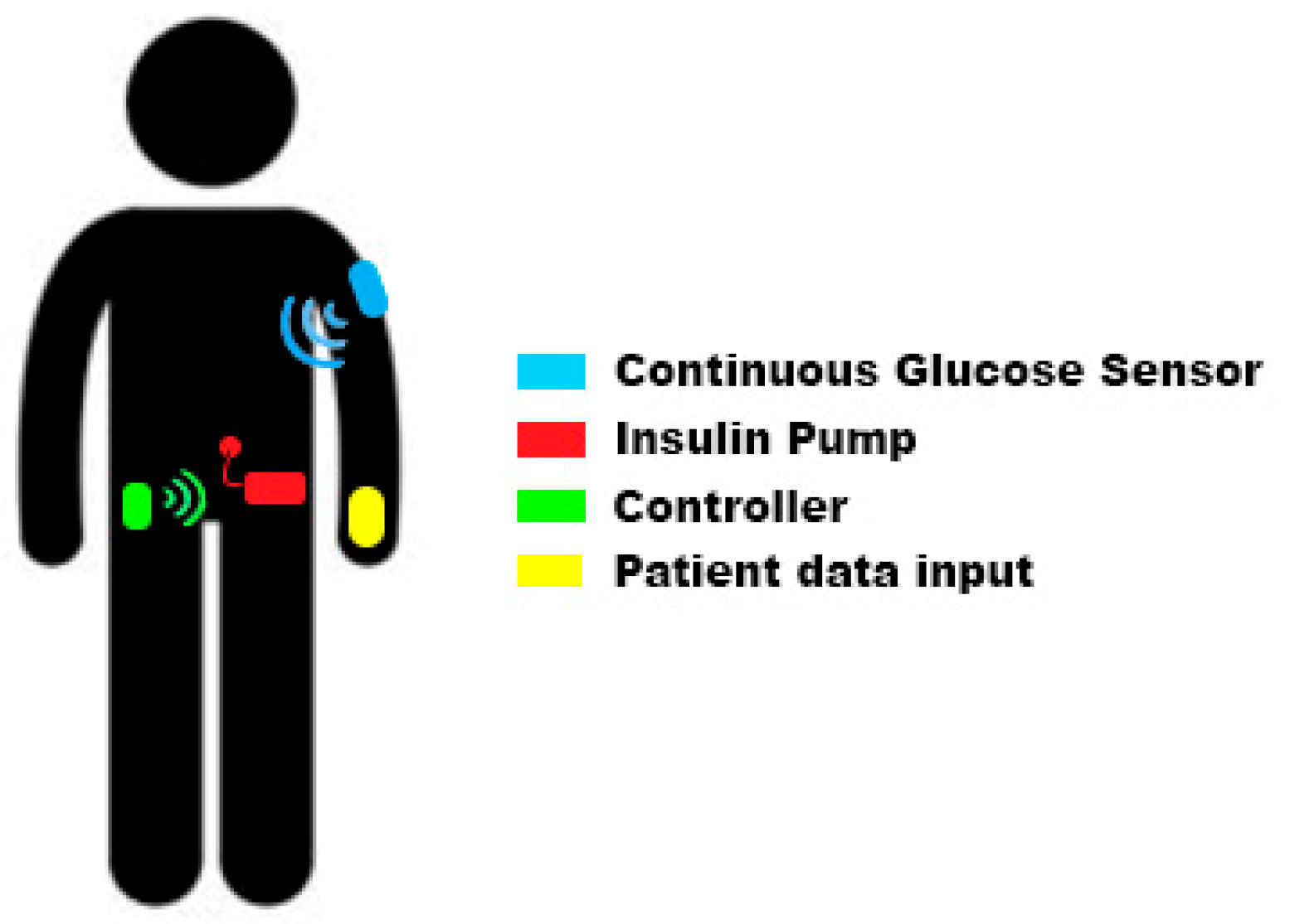
Our proposed closed-loop system is composed by four different elements: insulin pump, continuous glucose sensor, controller, and data input device (see Figure 1). Some of these elements (or all of them) could be integrated inside the same device.
Current commercial insulin pumps are designed to work in open loop mode, therefore, they operate in a way that meets the needs for the patients in this situation: insulin pumps allow insulin boluses (equivalent to an insulin injection) and the infusion of basal profiles. A basal profile (commonly named as “basals”) defines the different amounts of insulin the patient needs throughout the day to keep his glycaemia stable. As basal needs may change depending on many external factors, pumps typically support more than one basal profile to allow patients to select among them and use the one that best fits their needs in every moment. This basal profile selection is normally done in a type-of-day basis but, if users need to modify their basal infusion for a reduced period of time (from 30 min to some hours) insulin pumps allow “temporary basals.” Using a temporary basal the patient can manually increase or decrease the infusion without modifying the programmed basal profile. An insulin pump will be suitable for a closed-loop insulin delivery system if it can be controlled by an external device and supports the change of the infusion configuration: typically setting temporary basals.
The Continuous Glucose Sensor provides the control system with real time information about the patient’s glycaemia. The sensor is a module composed by a filament inserted under the patient’s skin measuring the glucose concentration and the associated electronics to perform the measurement, and the radio frequency transmission. Current glucose sensors obtain a new reading every 5 min and most of them must be calibrated by the patient in order to get precise enough results. Since the sensor is not measuring directly the glucose concentration present in the blood stream, there is a variable delay between what the glucose sensor is measuring and the real blood glucose concentration. This delay is typically 10/15 min and is one of the reasons why the sensor calibration must be performed when the patient’s glycaemia is stable. If the glycaemia is stable both measurements should match when calibrating.
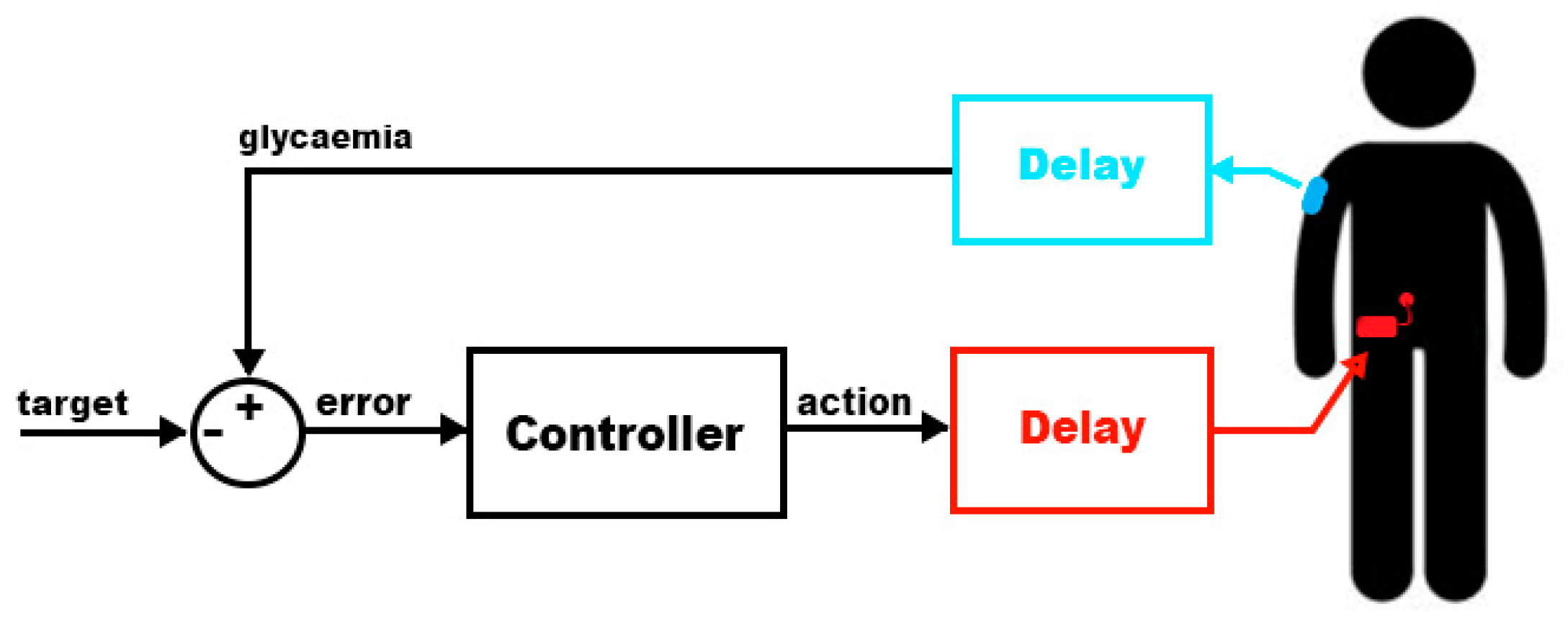
This type of system usually requires input from the patient and that is why they are called “hybrid” closed-loop systems. The main reason for this information need is the delay present in the measurement process and in the action (as shown in Figure 2).
- Glucose information delay: as explained above, there is a delay of 10/15 min in the glucose measurement process. This reduces the speed in which the controller can act to compensate rapid glycaemia changes.
- Insulin response: the patient will receive insulin via subcutaneous infusion. This process introduces a new delay in the loop system: the effect of the insulin will not be present in the patient’s body until it starts being absorbed while in a person without diabetes insulin effect has no delay [12]. Figure 3 compares the relative effects versus time of several types of insulin. As can be seen, the endogenous insulin (the one generated by a healthy pancreas) has an almost immediate effect that ends after one hour of its delivery inside the body. The rest of the insulins are some of the synthetic types a diabetic patient could use. Pump users typically use the fastest insulin available since the long-acting effect can be achieved with programmed basal profiles. Even with the fastest insulin (“Rapid-acting” in Figure 3) the peak effect occurs after 1 h from its infusion and it will be causing an effect up to 8 h.
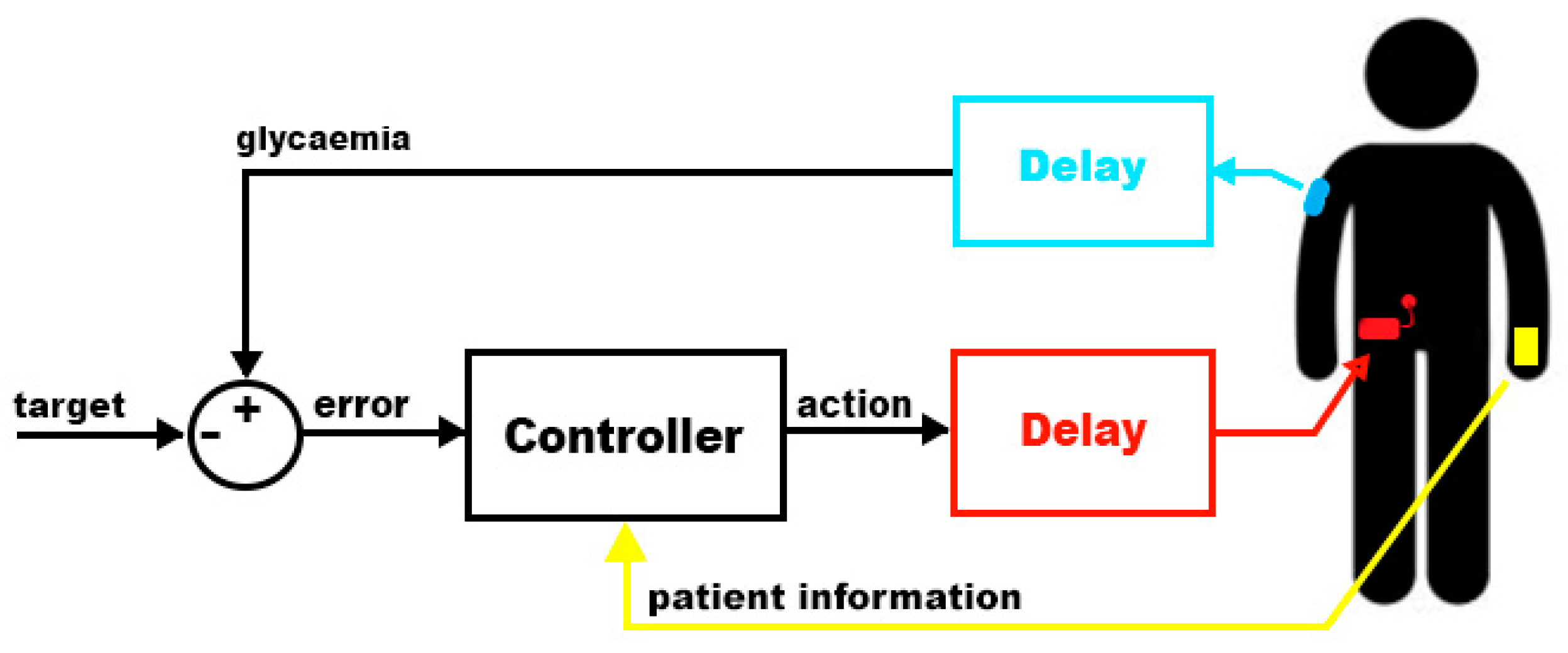
Although a closed loop system would respond effectively even with these delays inside the loop, they would cause the patient’s glycaemia to reach certain levels that are considered dangerous or, at least, not recommended. There are situations in which patients will experience rapid changes in their glycaemia: food intake and exercise. A rich carbohydrate meal will increase rapidly the glycaemia and, by the time the controller is capable to react, the patient could easily reach hyperglycaemia. During exercise, insulin requirements are lower and, if insulin is not reduced soon after, or even before, the exercise the patient could suffer hypoglycaemia. The controller will detect the glycaemia dropping 15 min after the real drop and will reduce the insulin infusion but, as insulin will remain active for many hours (depending on the patient), the effect of the infusion reduction could not be enough. In order to minimize this problem, the controller will receive information from the user to announce meals and exercise before they happen using a device like a smartphone (Figure 4). This way the controller will change the infusion to adapt to the future situation.
The controller is the module responsible for the information analysis and response calculation. In order to be considered as wearable it should meet these requirements:
- Battery with capacity enough to last 24 h in normal operation. Twenty-four hours is the minimum period of time that the controller should be capable of being active between charges so that the patient can recharge it while sleeping.
- Smallest size possible. Patients should be able to store it somewhere in their clothes. To be considered as “wearable,” the system must be comfortable, lightweight, and almost unnoticeable by the patient while wearing it.
- Be tolerant to communication failures. The controller will communicate with the glucose sensor and the insulin pump via radio frequency, therefore, the probability of having errors is significant. The controller should be tolerant to errors and should not take actions that, in the event of a loss of communication with the pump, would leave the rest of the system in a dangerous situation.
2.2. Proposed Wearable System for Insulin Delivery
Once the needed specifications for a wearable insulin delivery system are established, in this section, a new proposal that fulfils these requirements will be described. It will be composed by an insulin pump, a glucose sensor, and an ad-hoc controller based on a low power consumption system-on-chip.
The proposed system uses a commercial insulin pump with an integrated glucose sensor (Medtronic Paradigm Veo + Enlite sensor) because its communication protocol via radiofrequency has been documented [13,14] and can be controlled to set temporary basal levels, suspend and resume the infusion and/or command boluses.
As important as having a controllable infusion system is having a calibrated system. Enlite glucose sensors [15] require calibration every 12 h (maximum) and they must be calibrated by the patient following a specific set of rules:
- The glucose sensor will match the reading from the sensor with a glycaemia provided by the patient. This glycaemia value must be obtained with a glucometer following the steps provided by the manufacturer, typically: wash and clean hands before obtaining the blood sample and discard the first drop of blood to avoid external agents from the skin.
- Due to the delay between the glycaemia measured directly in the blood stream and in the interstitial fluids, calibrations must be only performed while the patient’s glycaemia is stable. This way the error is reduced as both readings should match after the time equivalent to the delay.
This process is necessary to keep the coherency between measurements in the interstitial fluid (provided by the glucose sensor) and in the blood stream (provided by a glucometer during calibration). The calibration of the sensor becomes really important in a closed-loop system: if the sensor is degraded or not calibrated correctly, the use of inaccurate data could cause a hypoglycaemia or hyperglycaemia to the patient.
Once the patient is using a reliable and controllable insulin infusion system along with a glucose sensor, the next step is to obtain a wearable platform that will enable the patient to close the loop: obtain real time glucose data and patient’s parameters and act on the insulin infusion.
Other platforms used for DIY closed-loop insulin delivery systems [6,7] use powerful microprocessors running operating systems as Linux, Android, or iOS. These platforms are not oriented to a low power consumption and they must keep the system running, having other processes in the background that could consume power in an undesired way. This is the reason why these platforms cannot be considered as “wearable.” In order to keep these systems running on batteries for at least 24 h, the patient must carry relatively big batteries with the system, making it less portable and, maybe, not reliable for a long-term period of time. When the controller runs on a smartphone there are two additional problems: the patient’s phone cannot run out of battery. In that case the patient will open the loop. Other intrinsic problem is the security risk of being hacked. Mobile phone security has to be improved in the next generations of OS for mobile phones. These two problems made this work face the controller’s problem from an embedded platform point of view.
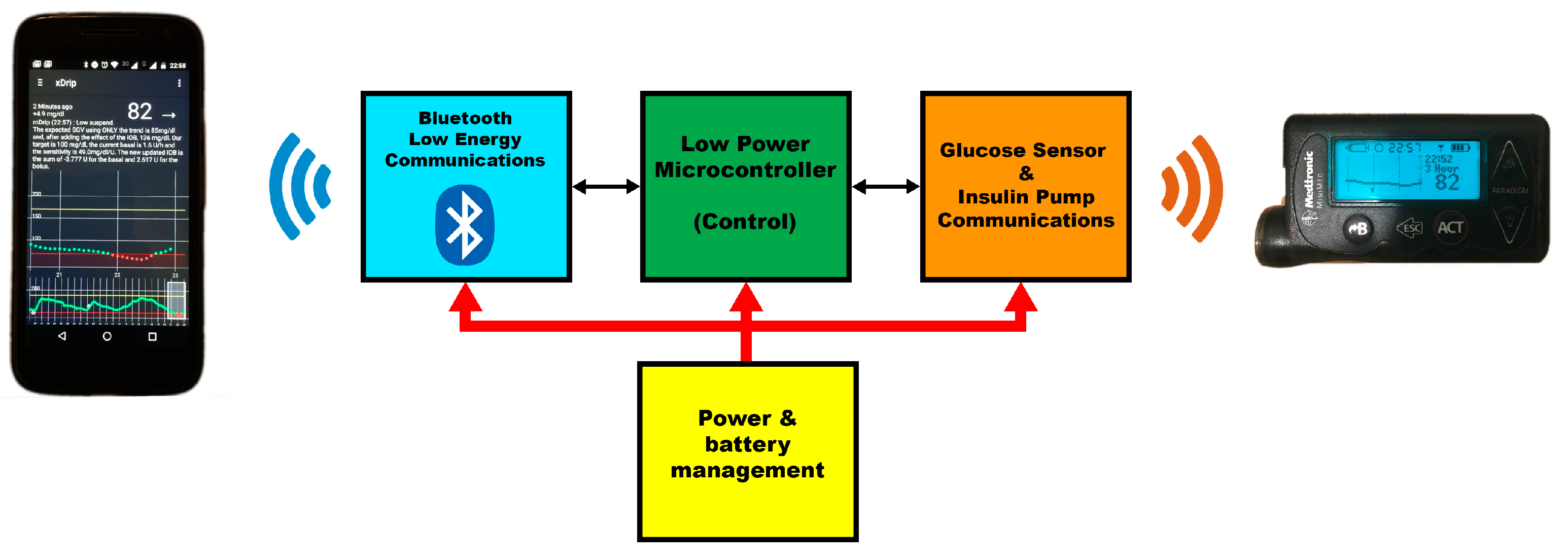
In the proposed solution, with low power consumption as a goal, a new custom board was designed. This board is divided into four different parts (diagram in Figure 5):
- Power and battery management: as this will be a battery powered module, some electronics are added to be able to charge the battery and to keep the battery under control.
- Low Power Microcontroller: the control algorithm is coded to run in a Low Power consumption 8051 core. As the controller will receive a new glucose data every 5 min, the controller can sleep the processor during the wait period and reduce the power consumption. Although this microcontroller uses technology from many years ago, its low power consumption makes it the ideal platform for this system.
- Bluetooth Low Energy Communications: this board has a Bluetooth interface to be able to communicate with a smartphone. Using a smartphone, the user can configure the controller and notify external events. It can also be used for remote monitoring purposes like, for instance, Nightscout [8].
- Glucose sensor and Insulin pump Communications: this is the interface used to retrieve information from the sensor and the pump, as well as command actions to the insulin pump.
2.3. Closed-Loop Control
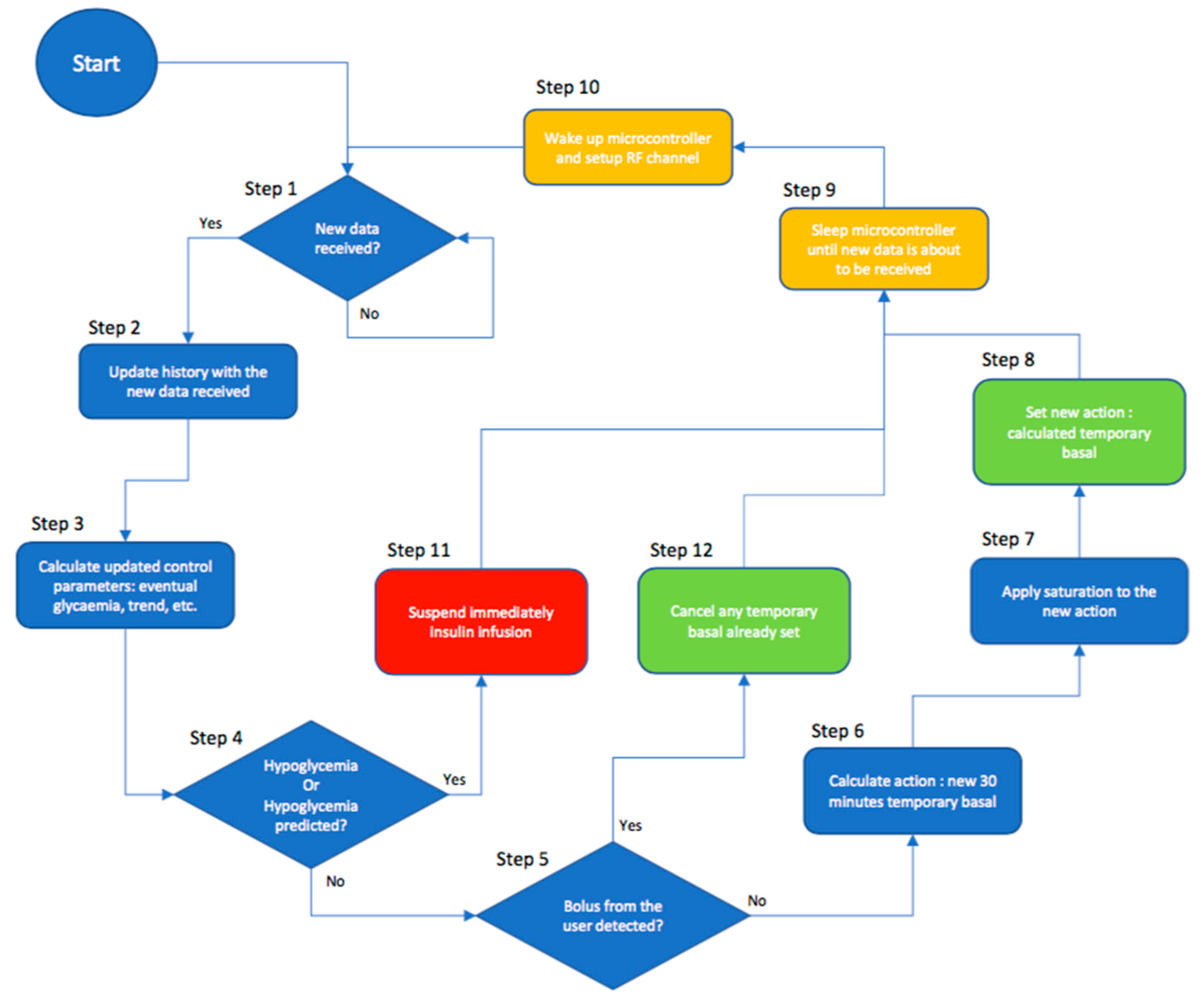
The control loop algorithm will be responsible for the data analysis and actions in the form of temporary basals. Its only purpose will be to command temporary basals to the insulin pump so that the measured glycaemia reaches a certain target value. To do so, the control algorithm was divided into several steps, as shown in Figure 6.
The control loop takes the following information as input:
- Infused insulin: previously infused insulin will impact the patient’s glycaemia even after more than 6 h from its infusion time. This time will vary from patient to patient and also depends on the type of insulin being used.
- Glycaemia: measured by the continuous glucose sensor. Current and past glycaemia values will define the current and eventual status for the patient. The glycaemia is the value the controller will modify to obtain a certain target.
The first thing the control algorithm needs is the updated glycaemia. In step 1 the algorithm will wait until a new glucose value is received from the sensor and, in step 2, the controller will update its history data with the received data.
Once the patient state has been updated, in step 3 the controller will retrieve the pump configuration with some parameters set for and by the patient and, after that, it will calculate some derived parameters needed for the control itself. As every patient needs a different model, it is not feasible to find a universal solution and, therefore, there are some parameters that the patient will need to enter according to his personal characteristics:
- Active Insulin Time: every type of insulin and every patient respond in a different way to the infusion of one unit of insulin. The parameter “Active Insulin Time” makes reference to the time that one unit of insulin keeps affecting the patient’s body.
- Basal profile: this profile describes the insulin needs the patients have throughout the day to make their glycaemia stable (in absence of other external factors).
- Sensitivities: Sensitivity or Insulin Sensitivity Factor establishes the relation between one unit of insulin and the glucose concentration that it will reduce in the patient. As happens with the basal profile, the sensitivity changes throughout the day and they are normally configured as a profile.
Once the system has obtained all these parameters and previous information, the control loop will start to operate. The controller will receive a new glycaemia value every 5 min; this allows the system to remain asleep for long periods of time and increase battery life.
As the system has 5 min to do all the calculations needed for the closed loop algorithm, low performance platforms can be used improving power consumption and cost. As a first step, the controller calculates three parameters (eventual glycaemia using only the trend, Insulin-On-Board, and eventual glycaemia) based on all the different inputs:
- Eventual glycaemia using only the trend (Equation (1)): using the history of glucose values sent by the sensor (sgv or sensor glucose value, 0 being the latest value received) the controller calculates the trend for the last ‘M’ values and the glucose value that the patient would reach after 15 min (using TS and the time in minutes between consecutive glucose values) if the glycaemia continues with that trend. This way, the controller tries to guess the current blood glucose value and reduce the error introduced by the sensor’s delay.
- IOB or Insulin-On-Board for one bolus or dosing (Equation (2)): every bolus or insulin delivered to the patient will affect blood glucose following a certain “insulin_response” curve. This curve represents the normalized effect of one unit of the chosen insulin from the infusion moment up to a certain number of hours (active insulin time). This way, the integral of the response curve from the moment chosen for the IOB evaluation (X, measured in hours) to infinity, multiplied by the number of insulin units delivered (B), will be equal to the equivalent amount of insulin that will still have an effect in the patient’s body in the future due to that bolus.
- IOB or Insulin-On-Board (Equation (3)): using all the previously infused insulin (basal and boluses, taking basals as a series of boluses every 5 min), the controller calculates the amount of insulin that has been infused but has not made an effect yet. That insulin is called Insulin-On-Board and has to be considered when calculating the final glycaemia. IOB will be calculated as the sum of every past infusion IOB (bIOB). The arrival of a new glucose sensor value will trigger the calculation process, so it can be assumed that every bolus or basal insulin can be analyzed as separate boluses with the periodicity of the glucose readings (Ts, measured in minutes). Every bolus or infusion will have its corresponding amount of insulin (Bn). Variable n will serve as discrete index in the equation.
- Eventual glycaemia (Equation (4)): the IOB has an important role: the eventual glycaemia, understood as the glycaemia to which the patient is heading, is calculated by the controller as the eventual glycaemia using only the trend plus the effect of the IOB. The parameter that relates insulin to modifications in the glycaemia is the insulin sensitivity factor (ISF) and is defined as the glucose concentration that one unit of insulin will reduce. The controller will use the insulin sensitivity factor that corresponds to the current time and will multiply it by the IOB previously calculated. This multiplication will give to the controller the expected modification for the glycaemia. Summing up this value to the eventual glycaemia using only the trend the controller obtains the eventual glycaemia.
At this point, the controller has all the input information and parameters for the patient and all the derived data from them. The controller operation can be divided into four layers evaluated in a sequential manner:
- Safety Layer (steps 4 and 11 from Figure 6): in this layer, using the current glycaemia (sgv[0]), eventual glycaemia (eGlyc), and eventually using only the trend glycaemia (eGlycTrend) the controller will suspend the insulin infusion in case any of them are below a certain safety threshold ( (see Equation (5)). This same layer will resume the infusion as soon as the hypoglycaemia disappears. In the case of a suspension in this layer, the control loop execution stops until new data is received.
- Bolus Snooze Layer (steps 5 and 12 from Figure 6): once the controller determines that the patient is not suffering or in risk of a hypoglycaemia, it will check if the patient infused an insulin bolus (step 5). If a bolus was infused, the controller will cancel any temporary basal (step 12) until the peak of effect of the bolus (which depends on the Active Insulin Time). The controller will suppose that the bolus was set to compensate the effect of some food intake and it will not affect the calculation made by the patient for the bolus. After that period of time, the controller will resume the control and compensate if needed
- Control Layer (step 6 from Figure 6): using the patient’s parameters for the current time, the controller calculates the error between the eventual glycaemia and the glycaemia set as target (see Equation (6)). Using the insulin sensitivity factor for that specific time of the day (ISF), the controller is able to calculate the amount of insulin needed to cancel the error (see Equation (7)). That insulin is infused as an addition to the basal needed by the patient, so the controller calculates a new basal rate lasting 30 min (the minimum that the insulin pump permits) that is the result of the basal rate programmed for that period of time (basal) plus the correction insulin distributed through those 30 min (see Equation (8)). If the eventual glycaemia is lower than the target, the resulting temporary basal will be lower than the programmed one for that time.
- Action Saturation Layer (steps 7 and 8 from Figure 6): in step 7 the controller limits the actions taken by the control layer. The minimum temporary basal allowed is 0 U/h (Units per hour) and the maximum temporary basal is set as another parameter by the user in the insulin pump. That parameter is called “Max basal.” Any temporary basal over that limit will be reduced to the maximum basal allowed. After applying the saturation effect to the calculated temporary basal, it is commanded to the pump in step 8.
As explained before, this control loop has been designed to work on a low-power-consumption embedded platform and, having reached this point in the execution, the control loop will sleep the microcontroller to save energy (step 9 from Figure 6). Just before a new glucose value is sent, the microcontroller will wake up and set up the radio frequency channel to be ready for it (step 10 from Figure 6). The control loop algorithm takes approximately 15 s to calculate and command new actions and, if the glucose sensor sends a new glucose value every 5 min, the microcontroller will sleep for more than 90% of the time.
Although the control algorithm would work properly with some degree of error in the parameters entered by the patient, this controller should be configured as accurately as possible in order to have good results. Some of the effects that the patient could suffer from misconfigured parameters are:
- If the Active Insulin Time does not match the patient’s actual one, the expected variations due to the infused insulin will not match the real ones. If the real time is higher and the patient is suffering a hyperglycaemia, the control loop will continue dosing more insulin to correct it without waiting until all the insulin has made effect (possibly causing a hypoglycaemia). On the other hand, if the real time is lower, it will not dose the needed insulin since the controller will wait longer for the insulin to make effect (unrealistically).
- If the basal profile does not match the patient’s real one, the corrections will be biased due to that error. For example, in the case of hyperglycaemia, if the programmed basal is lower than the real needs and the correction plus the programmed basal are still lower than the real basal, the controller would never reduce the error and, therefore, take the patient’s glycaemia to target. Something similar would happen in the case of hypoglycaemia and a correction plus a programmed basal higher than the real basal, the controller would never reduce the error and would lower the patient’s glycaemia (with the risk of causing severe hypoglycaemia).
- If programmed insulin sensitivity factors do not match the patient’s real ones the controller will modify the expected response. If the programmed sensitivity is lower than the real one, and depending on the glycaemic error, the controller could infuse too much insulin to correct that error, causing hypoglycaemia. If the sensitivity is higher than the real one, the controller will have a slow response and it will take more time to get to target.
As explained before, some degree of error can be tolerated but, if the error is big enough to cause a non-automatically-solvable situation, an alarm will be sent to the smartphone so that the patient is notified and can take care of the problem.
2.4. Safety
This control algorithm’s first goal is to keep the patient safe. Safety features have been implemented in several parts of the system in the form of alarms and action types. As it has been described before, this control platform is based on the fact that the patient is already using a commercial system for glucose sensing and insulin delivery. These systems have their own alarm system being able to report hypoglycemic or hyperglycemic situations directly to the patient. On top of that, our control platform makes use of a third-party software named xDrip [16] to upload data to Nightscout and for data monitoring directly on the phone. xDrip also provides a really powerful alarm system in which the patient can configure the standard alarms (hypo, hyper), rate change alarms or data stalling alarms (for a programmable time period). In the proposed platform, xDrip can also generate alarms coming from the controller. This feature is used to alarm the user from non-mitigatable problems like a precited hypoglycemia that cannot be solved just by reducing the future amount of insulin being delivered, requiring the patient interaction or a persistent hyperglycemia that the system fails to lower, meaning that the patient may need to review the infusion set or the correct state of the insulin.
Safety was also taken into account in the way insulin is controlled. There are two main ways of controlling infusion:
- Micro-bolusing: the insulin pump only injects insulin when the controller commands it in the form of small boluses.
- Temporary basals: the insulin pump has a programmed basal rate profile that should cover the patient’s basal needs during the day and the controller will issue temporary basal rates to change the insulin infusion when needed.
If the control algorithm resides inside the insulin pump any of those methods can be understood as safe but, as we have to rely on the radiofrequency communications that could or could not be operational, micro-bolusing is not a safe option: to be able to use micro-bolusing the patient must disable any basal rate infusion since there would be no other way to reduce the amount of insulin the patient receives below that basal rate (there would be no way to suspend infusion). Disabling the basal rate is potentially dangerous since any problem with the controller or the communications would leave the patient without insulin and that situation could lead the patient to suffer from DKA (Diabetic Ketoacidosis). Due to this reason, this controller makes use of temporary basal rates to control infusion. The patient has a valid basal rate profile configured and the controller will issue 30 min temporary basal rates to add or reduce insulin. In the case of a controller or communications failure, after those 30 min, the insulin pump will come back to its normal behavior and will infuse the programmed basal rate.
One more problem mitigated with the use of temporary basal rates is that, in the case of an uncontrolled loop execution (execution error event), one temporary basal will directly cancel the previous one while, in the case of micro-boluses, the system could potentially command many boluses in a row stacking their effects (and possibly causing a severe hypoglycemic event).
With the use of temporary basal rates the controller has another safety feature: the insulin pump will only accept temporary basal rates that are higher than 0 U/h and lower or equal than a maximum rate that can be configured in the pump, this way constraining the possible actions that can be taken by the controller.
2.5. Security
One of the main concerns about using DIY systems [6,7] with outdated Medtronic pumps, apart from glycemic safety, is the lack of security in the communications channel between the controller and the insulin pump. Communications are not encrypted in any way and, while this fact makes the insulin pump easily accessible to the controller, it also makes it vulnerable to attackers who could try to remote control the pump and, therefore, be a potential risk for the user’s safety.
The controller will query the pump every 5 min and, by doing so, the pump ID is broadcasted several times with every data exchange. Every message will contain the pump ID so that it can be identified by the receiver and any other system waiting for those messages. These periods of time are critical since the pump ID is exposed and any attacker could potentially listen to it and use it later to send dangerous commands to the pump.
Medtronic has created a new communications protocol to address this problem encrypting the payload of the messages but, as this system makes use of the old model ones, an intrusion detection and jamming procedure was added to the controller.
The controller is always listening, looking for messages from/to the pump. If a message is received and it is not an answer to a command sent by the controller, an intrusion alarm will be sent to the smartphone to alert the user. At the same time, the jamming procedure is started: the controller will continuously send “Suspend” messages to the pump in an attempt to cancel any command sent to the pump while giving time to the user to take any action needed to protect himself from this situation. This continuous transmission will corrupt any message sent by the attacker, blocking the communications channel for some minutes.
This protection can be disabled to allow data download from the pump when the user needs it (for instance during a medical appointment).
3. Results
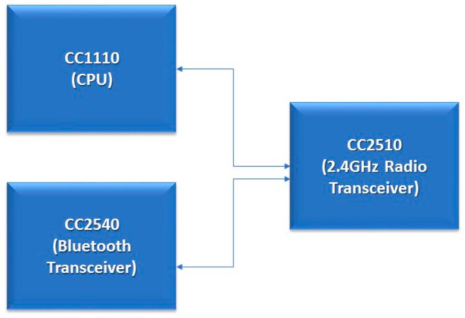
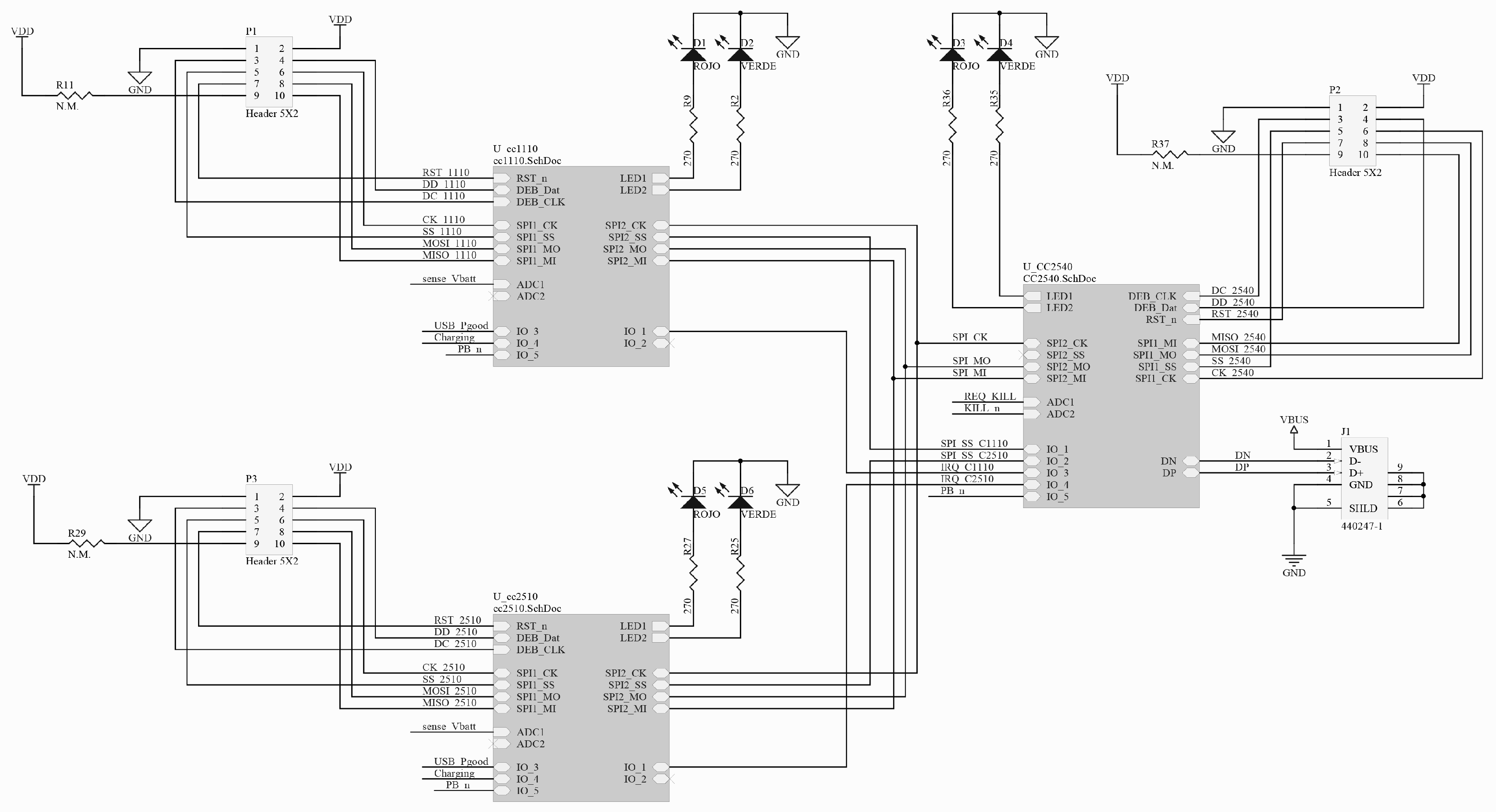
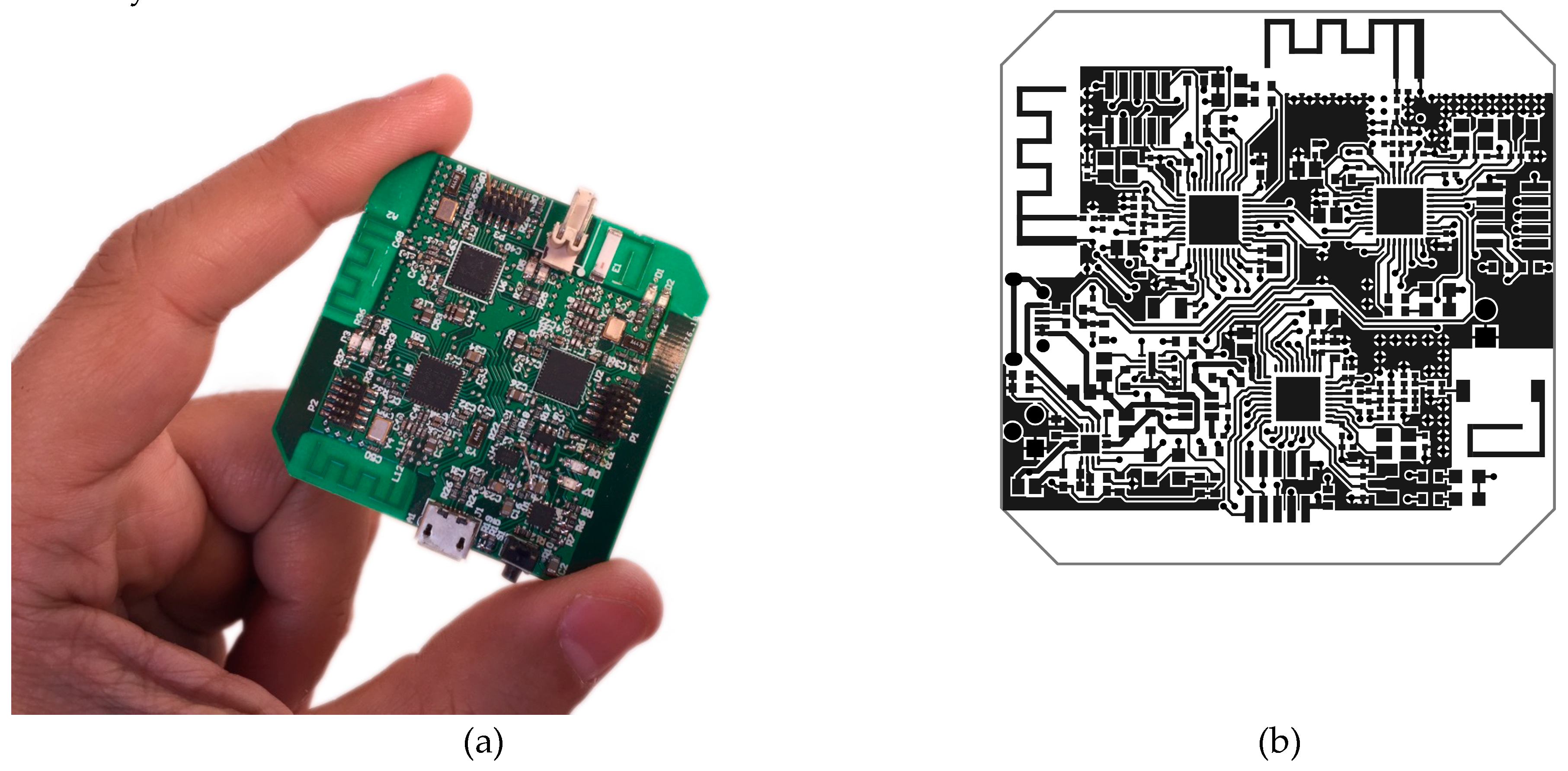
A new hardware platform (see Figure 7) was developed, following the previously mentioned requirements, to create a new automatic insulin delivery system based on the patient’s glycaemia and his specific parameters. Three system-on-chip ICs were included to support communications with Medtronic devices (Texas Instruments CC1110 [17]), Bluetooth Low Energy devices in Central Role mode (Texas Instruments CC2540 [18]) and, although it is not necessary right now, other 2.4 GHz devices for future developments (Texas Instruments CC2510 [19]). All three system-on-chips apart from the RF transceiver incorporate an 8051 processor and were used to implement, among other functionalities, the control loop algorithm (see Figure 7 and Figure 8). All of them can enter really low power modes in which they reduce their consumption down to 0.3 µA (PM3 mode).
As this module has to be wearable, a 680 mAh Lithium-Polymer battery with its regulation electronics were added (see U1 and U3 in Figure 9). This battery provides more than 24 h of operation enabling the patient to safely wear it during the day and recharge it during the night while still operating.
In addition, this new platform was integrated into the Nightscout platform [8] for remote monitoring and with xDrip [16] as a mobile platform to control it and upload information to the cloud. Therefore, this platform (shown in Figure 10) can be connected with cloud solutions to share and analyze information.
Using Nightscout, the user can control the performance of the loop and receive alarms when needed. Nightscout, as a platform, is a perfect way to adjust parameters as it enables the patient to log the information for meals, boluses, exercise, etc., and use this information for later analysis. Endocrinologists can benefit from this tool to make better adjustments as more information can be easily analyzed.
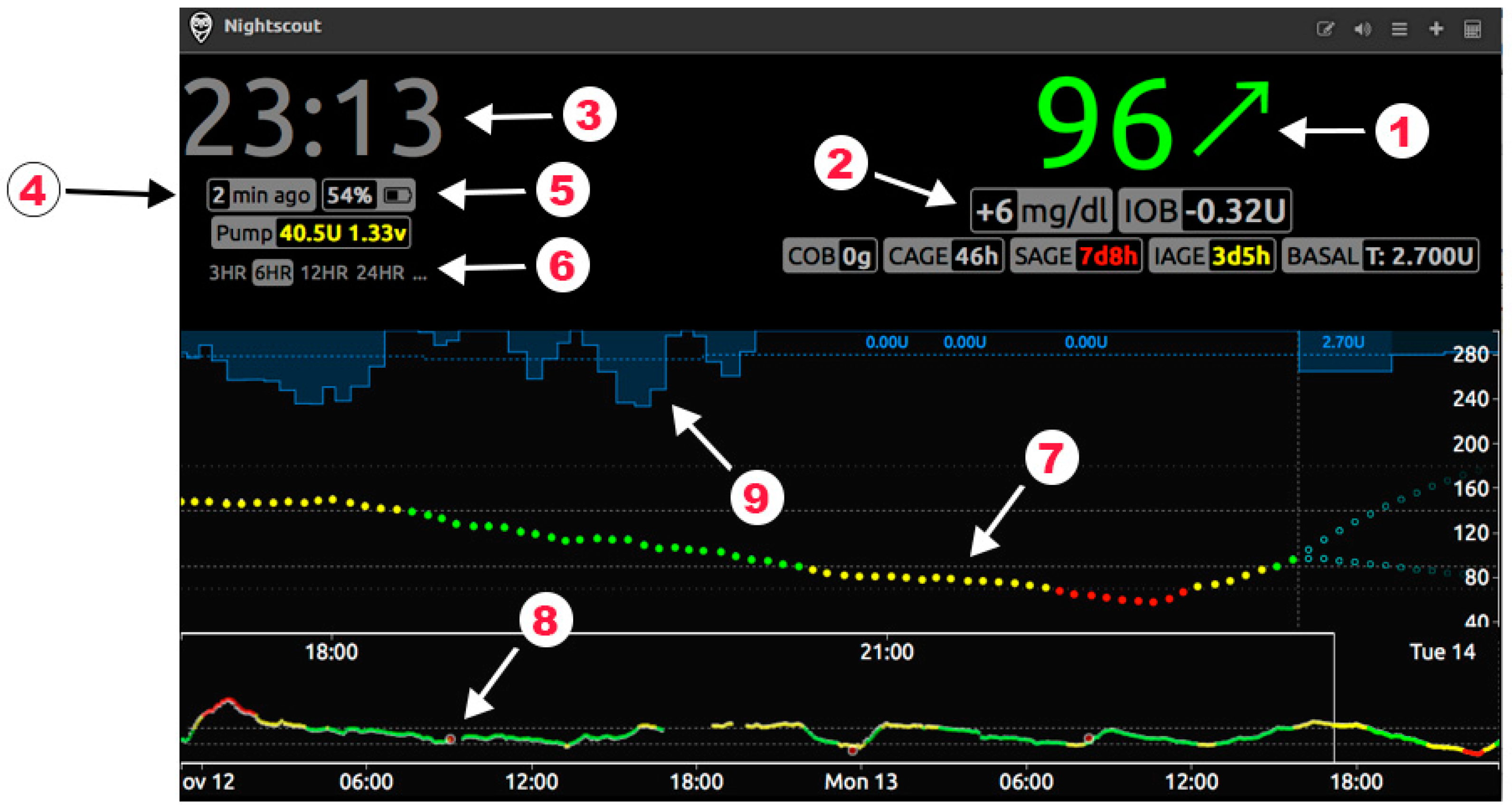
Figure 11 shows the typical Nightscout webpage a patient would see in normal operation. The big green number on the top right corner (item number 1) shows the current glycaemia and an arrow showing the trend. The dotted line (item number 7) shows the patient’s glycaemia in real time. In this case, the target range (green) is set to be 90–140 mg/dL. The bottom line (item number 8) shows two days of data while the middle one can show a configurable period of time (last 3, 6, 12 or 24 h) using selector number 6. The blue graph on top of the glycaemia line (item number 9) shows how the insulin infusion has been performed. Other parameters that can be monitored are:
- Current time (item number 3)
- IOB: current insulin on board
- Numeric trend (item number 2)
- COB: carbohydrates on board (if the user enter meal information)
- CAGE: Cannula Age. As a reminder for the patient to change the cannula when needed.
- SAGE: Sensor Age. As a way to monitor the time the sensor has been placed in the patient’s body.
- IAGE: Insulin Age. Show the time since the insulin reservoir was filled with insulin.
- BASAL: current basal or temporary basal set.
- PUMP: current insulin pump status (insulin left in the reservoir and battery voltage)
- Time since last reading and since last action from the controller (item number 4).
- Battery level for the smartphone uploading the data to the cloud (item number 5).
The proposed control algorithm will obtain good results as long as the user configures the parameters that match his/her needs (active insulin time, basal profile, and insulin sensibility factors) [20]. To test this control algorithm, an open-source simulator named simglucose [11] was used. This simulator is a python implementation of the FDA-approved UVa/Padova Simulator [21] for research purpose only that includes 30 virtual patients: 10 adolescents, 10 adults, and 10 children.
The patients’ configuration for the simulated insulin pump were set following standard methods and, as the parameters that vary from patient to patient are included in this configuration and their calculation is out of the scope of this article, it is assumed that results should not significantly vary among other possible patients. The algorithm should take the same decisions that the patient would normally take if he/she would be doing it manually every 5 min.
Three batches of simulations were run: one of them in open-loop mode without any intervention from the patient, one in open-loop mode but simulating the correction action from the patient administering correction boluses 2 h after every meal, and the other in closed-loop mode. All simulations used the same set of parameters and, although they differ from patient to patient, they were not modified from simulation to simulation. The following meal scenario was used:
- 07:00 -> 40 grams
- 13:00 -> 20 grams
- 17:00 -> 5 grams
- 20:00 -> 20 grams
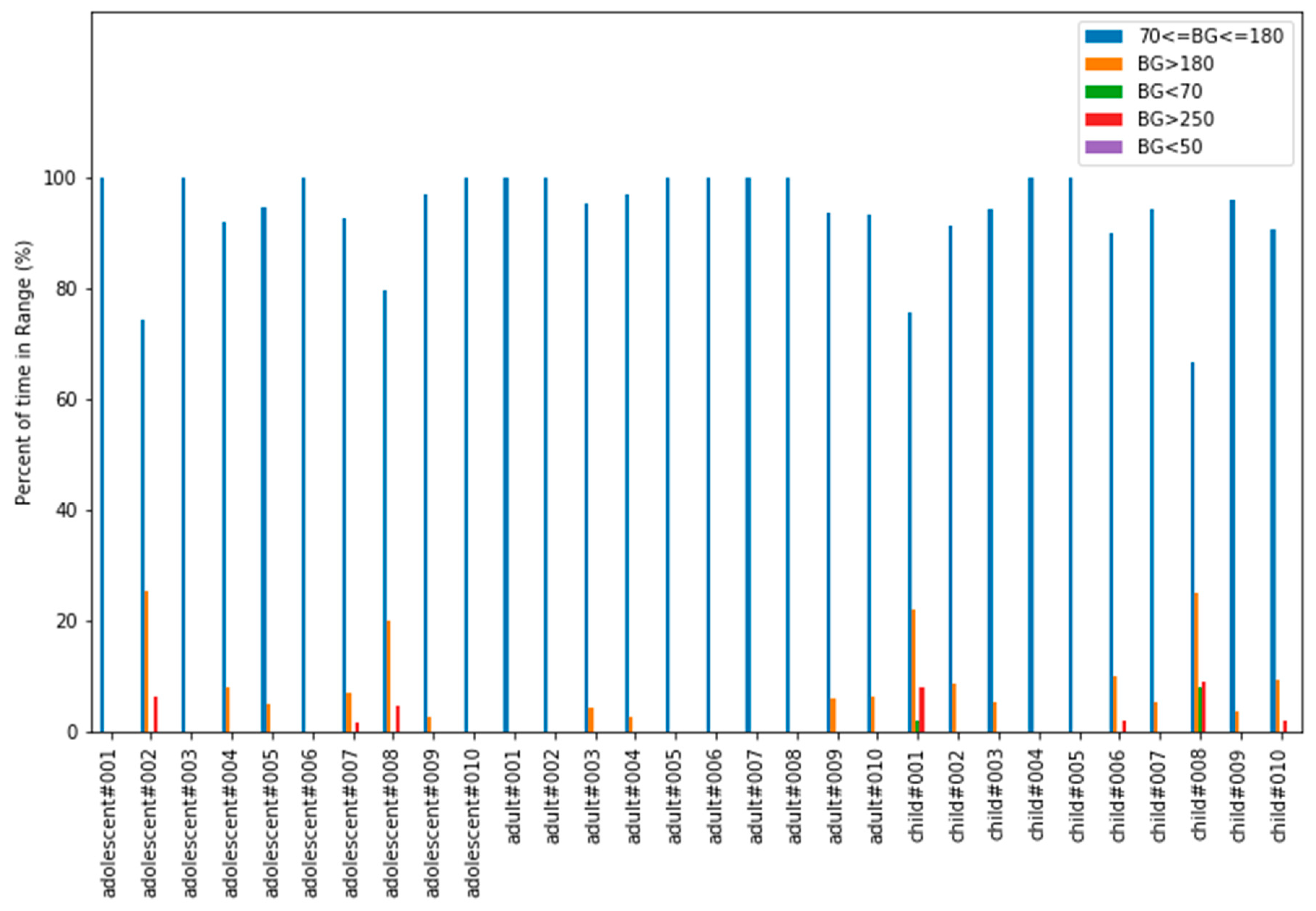
To evaluate results coming from these simulations, the “Time In Range” (TIR) parameter was used. “Time in Range” refers to the percentage of time a patient spends within his/her target glucose range, typically from 70 to 180 mg/dL. The most time the patient stays inside this range, the less likely he/she is to suffer from long-term complications in the future.
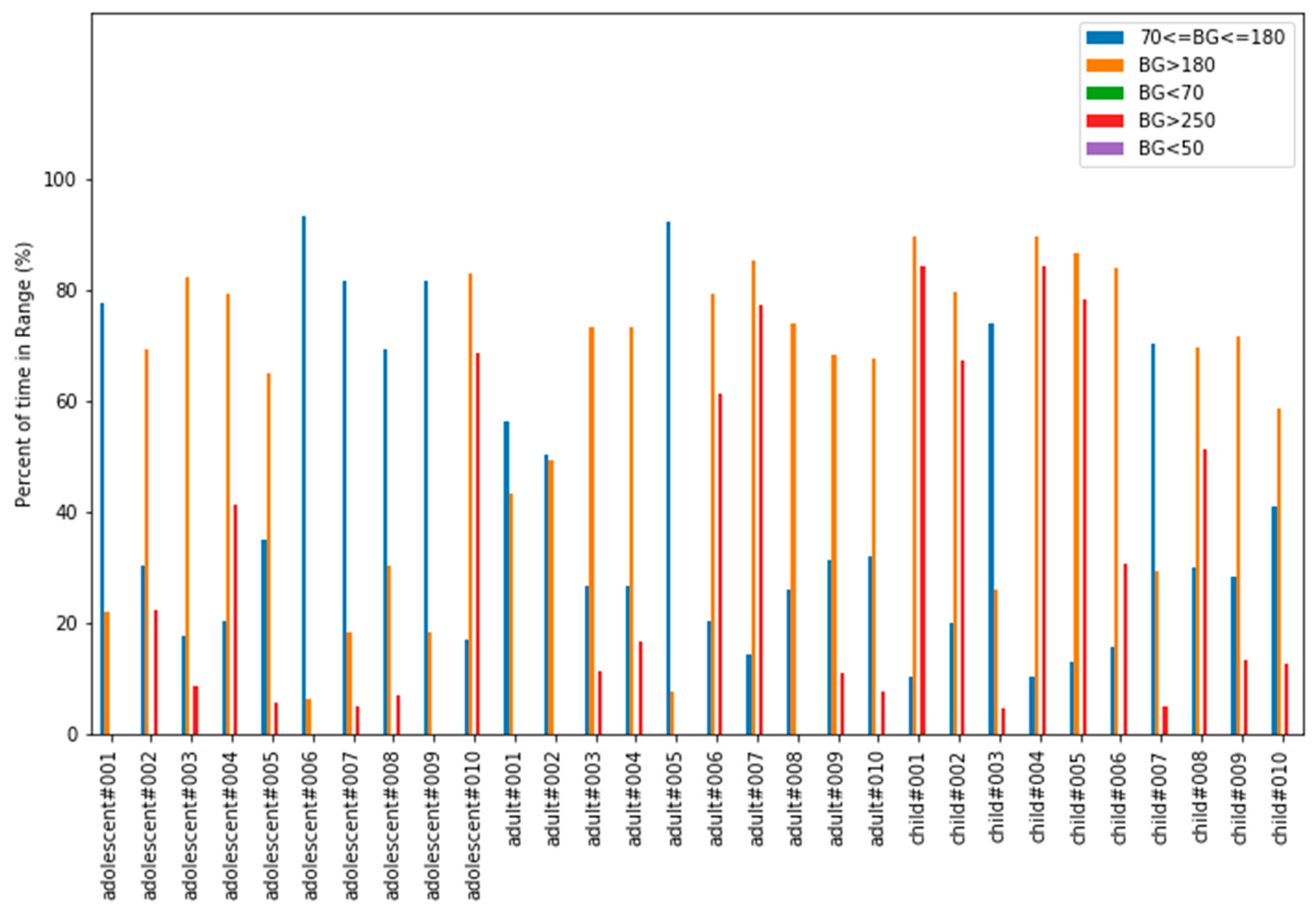
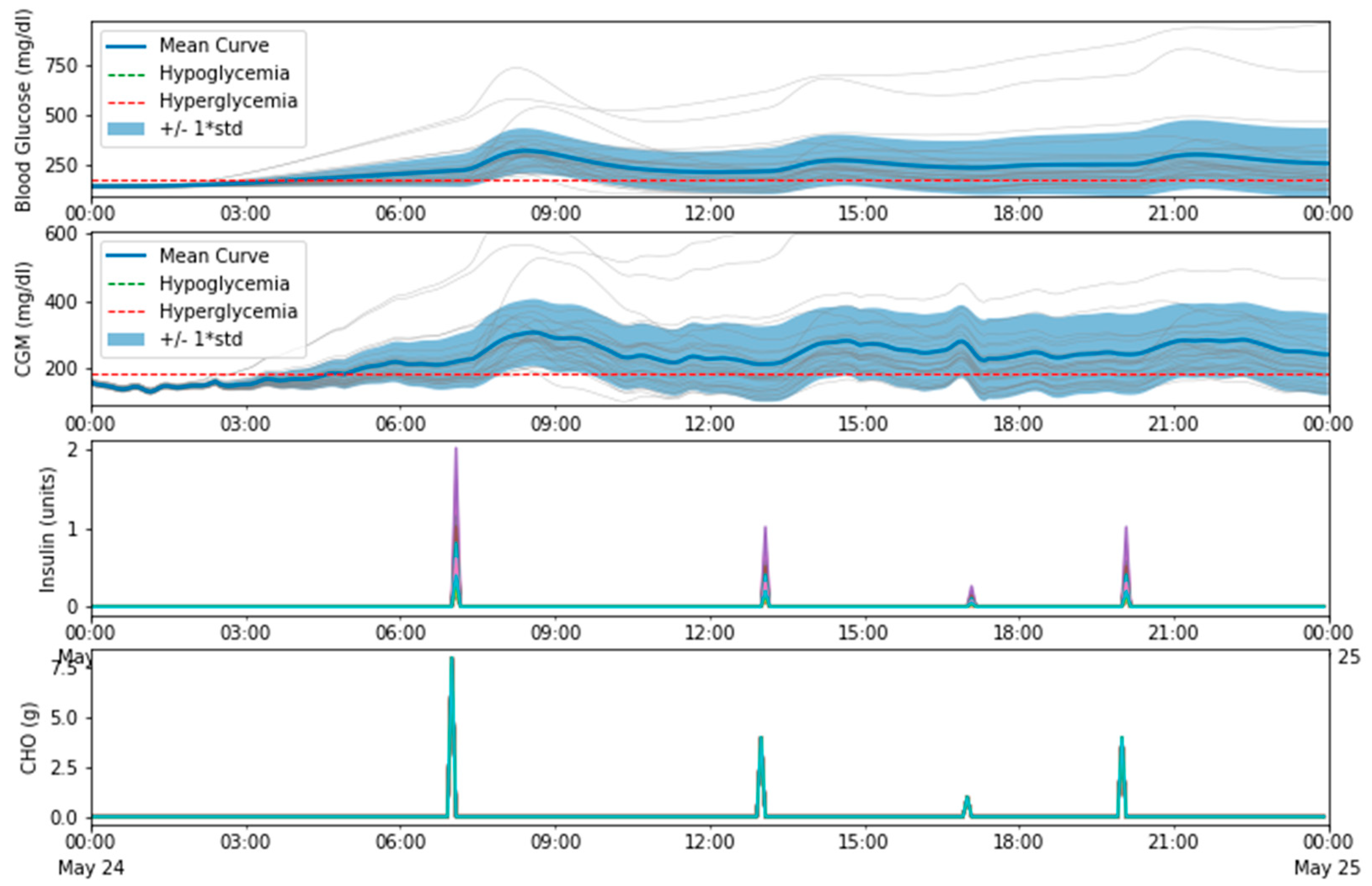
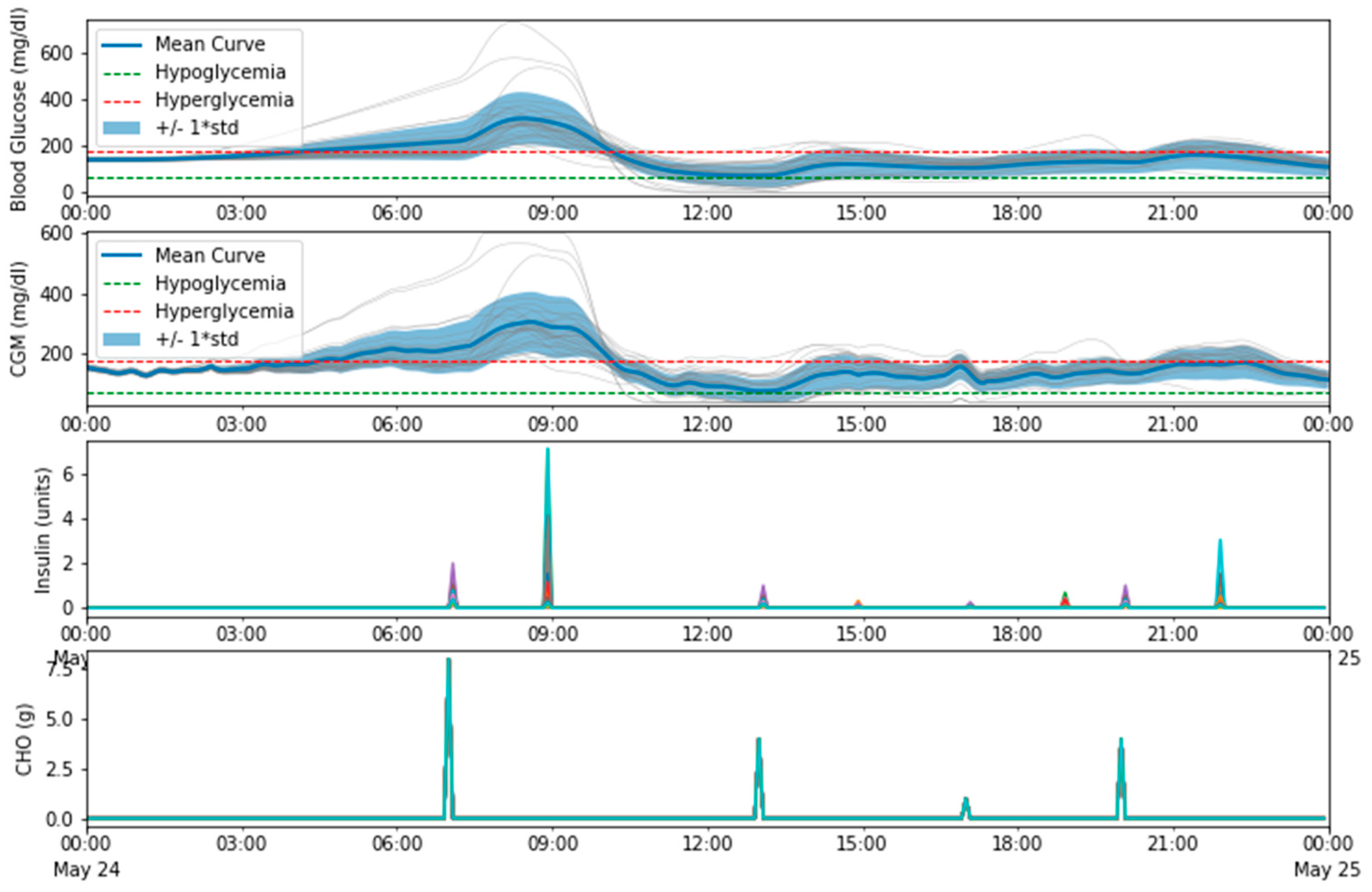
In open-loop mode without interaction from the patient, as can been seen in Figure 12 and Figure 13, most patients suffer from hyperglycemia more than 40% of the time. Figure 13 shows how glucose levels start rising with time and correction boluses would be necessary to put the patient back in range (70–180 mg/dL). Meal absorption is shown in terms of CHO (grams). CHO stands for Carbohydrates (Carbon Hydrogen Oxygen) and, in these simulations, the rate of absorption was set to 5 g per minute. Since the simulation step is 5 min, CHO is equivalent to the grams of the meal divided by five. This simulation obtained the following average TIR values: general 40.52%, adolescent 52.45%, adult 37.71%, child 31.41%.
In an attempt to simulate part of what a patient would do to correct hyperglycemias, a simulation in open-loop mode but allowing correction boluses was executed. These correction boluses occur 2 h after every meal only if hyperglycemia exists. As can be seen in Figure 14 and Figure 15 results improved, reaching a global average TIR percentage of 65.75%. The average TIRs per groups were: adolescent 77.78%, adult 67.23%, child 52.25%.
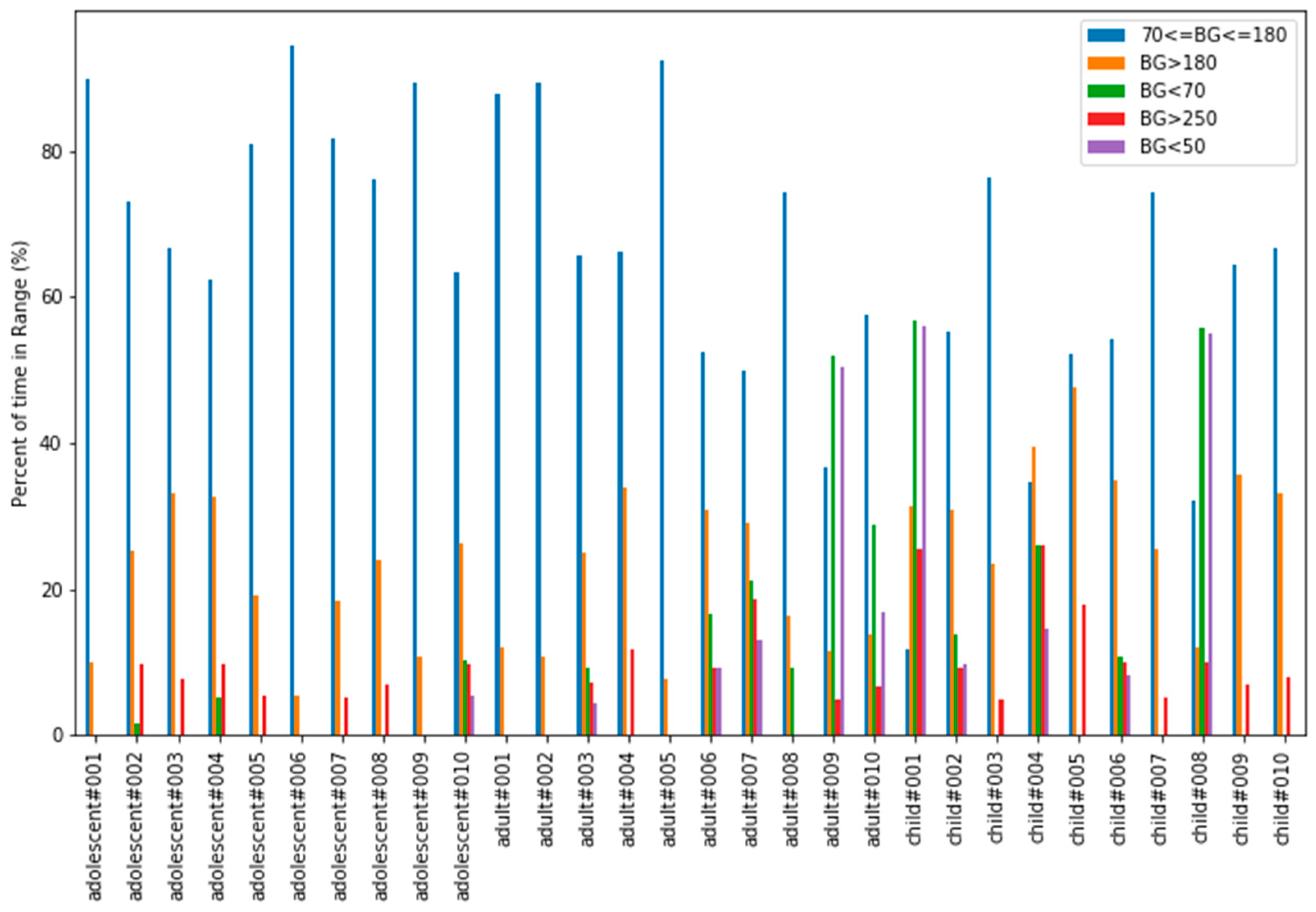
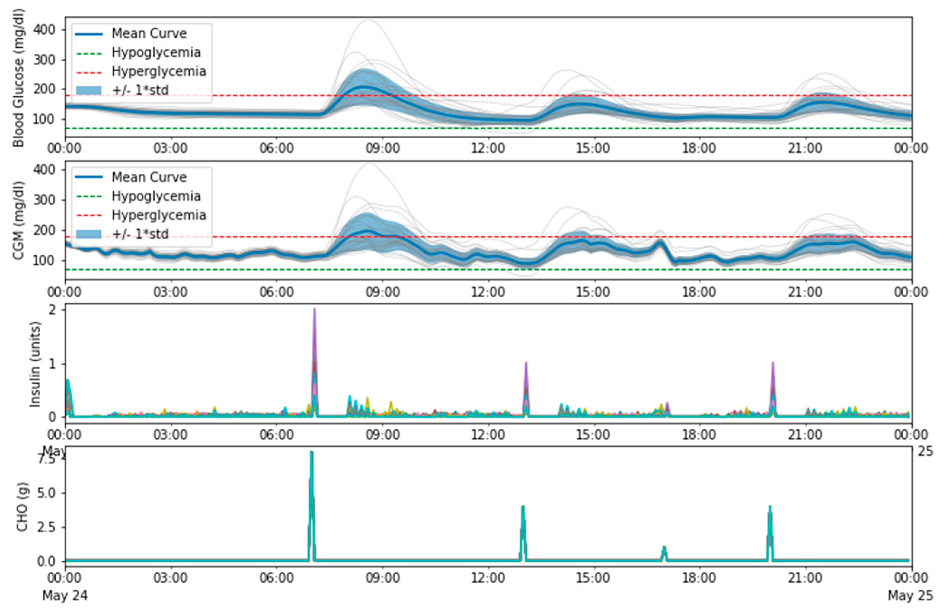
In closed-loop mode, simulating the same patients with the same meal scenario, TIR improves considerably as can be seen in Figure 16. Figure 17 shows how glucose levels are kept in range most of the time, and some patients suffer from small post-prandial hyperglycemic episodes. These episodes could be minimized applying pre-bolusing techniques (dosing insulin some time prior to the meal) but this simulator does not support it directly. This simulation obtained the following average TIR values: general 93.69%, adolescent 93.11%, adult 97.99%, child 89.96%. One really important thing to point out is that using a closed-loop system not only improves TIR but also reduces the burden the patient suffers. The system operates autonomously, and the patient does not need to spend so much time trying to keep his/her glucose levels in range.
4. Discussion
The typical recommendation when using a controller like this one is to stay in open loop mode for at least two weeks fine tuning these parameters before activating the closed-loop control. Unfortunately, setting these parameters correctly is not an easy task. Even with a controller perfectly configured, there are situations that will temporarily modify these parameters and that are not under the patient’s control: incorrectly estimated food intakes, illness, exercise, stress, hormonal disorders, and many others.
As these parameters can vary easily (even for one single patient) it seems reasonable to think that new models are needed so that these parameters can be estimated and that, in this way, any controller could do a better job. This is a good opportunity for the scientific community to use open platforms and obtain better control algorithms.
This controller offers a real solution that allows the patient to keep his glycaemia under control while being, at the same time, almost transparent and unnoticeable. Therefore, the proposal described in this work provides a new approach to improve the life of patients with this disease taking advantage of a glucose sensor, an ad-hoc processing unit, and a set of wireless channels of communication.
Author Contributions
Conceptualization, J.B. and S.H.; Methodology, I.B., A.G. and J.L.L.; Software, J.B. and S.H.; Validation, J.B. and I.B.; Investigation, J.B.; Writing—original draft preparation, J.B.; Writing—review and editing, I.B, A.G. and J.L.L.
Funding
This research received no external funding.
Acknowledgments
This system was created using other modules as a base: Nightscout was used for remote monitoring and visual control, xDrip Android App was modified to support this new platform and to upload glucose and control information in Nightscout. The insulin pump and the glucose sensor used were developed by Medtronic.
Conflicts of Interest
The authors declare no conflict of interest. The founding sponsors had no role in the design of the study; in the collection, analyses, or interpretation of data; in the writing of the manuscript, and in the decision to publish the results.
References
- American Diabetes Association. Available online: http://www.diabetes.org/diabetes-basics/statistics (accessed on 9 December 2018).
- Dexcom. Available online: www.dexcom.com (accessed on 9 December 2018).
- Continuous Glucose Monitoring—Medtronic. Available online: https://www.medtronicdiabetes.com/treatments/continuous-glucose-monitoring (accessed on 9 December 2018).
- Abbott Freestyle Libre. Flash Glucose Monitoring System. Available online: https://www.freestylelibre.us (accessed on 9 December 2018).
- Lee, H.; Buckingham, B.A.; Wilson, D.M.; Bequette, B.W. A Closed-Loop Artificial Pancreas Using Model Predictive Control and a Sliding Meal Size Estimator. JDST 2009, 3, 1082–1090. [Google Scholar] [CrossRef] [PubMed]
- Github repository for Loop. Available online: https://github.com/LoopKit/Loop (accessed on 9 December 2018).
- The Open Artificial Pancreas System #OpenAPS. Available online: https://openaps.org (accessed on 9 December 2018).
- Nightscout (CGM in the Cloud). Available online: http://www.nightscout.info (accessed on 9 December 2018).
- Doyle, F.J.; Huyett, L.M.; Lee, J.B.; Zisser, H.C.; Dassau, E. Closed-Loop Artificial Pancreas Systems: Engineering the Algorithms. Diabetes Care 2014, 37, 1191–1197. [Google Scholar] [CrossRef] [PubMed] [Green Version]
- Kudva, Y.C.; Carter, R.E.; Cobelli, C.; Basu, R.; Basu, A. Closed-Loop Artificial Pancreas Systems: Physiological Input to Enhance Next-Generation Devices. Diabetes Care 2014, 37, 1184–1190. [Google Scholar] [CrossRef] [PubMed] [Green Version]
- Xie, J. Simglucose v0.2.1 (2018). Available online: https://github.com/jxx123/simglucose (accessed on 9 December 2018).
- Freeman, J.S. Insulin Analog Therapy: Improving the Match with Physiologic Insulin Secretion Devices. Clin. Prac. 2009, 109, 26–36. [Google Scholar]
- Medtronic Veo RF Transceiver. Github repository. Available online: https://github.com/jberian/mmcommander (accessed on 9 December 2018).
- Medtronic Veo Commands. Github repository. Available online: https://github.com/bewest/decoding-carelink/tree/master/decocare (accessed on 9 December 2018).
- Medtronic Enlite Sensors. Available online: https://www.medtronicdiabetes.com/customer-support/sensors-and-transmitters-support (accessed on 9 December 2018).
- xDrip—Using your Dexcom G4 with Android. Available online: http://stephenblackwasalreadytaken.github.io/xDrip (accessed on 9 December 2018).
- Texas Instruments Low-Power SoC CC111x Datasheet. Available online: http://www.ti.com/lit/ds/symlink/cc1110-cc1111.pdf (accessed on 9 December 2018).
- Texas Instruments Low-Power SoC CC2540 Datasheet. Available online: http://www.ti.com/lit/ds/symlink/cc2540.pdf (accessed on 9 December 2018).
- Texas Instruments Low-Power SoC CC2510 Datasheet. Available online: http://www.ti.com/lit/ds/symlink/cc2510.pdf (accessed on 9 December 2018).
- Kovatchev, B.P. Diabetes Technology: Markers, Monitoring, Assessment, and Control of Blood Glucose Fluctuations in Diabetes. Scientifica 2012, 283821. [Google Scholar] [CrossRef] [PubMed]
- Man, C.D.; Micheletto, F.; Lv, D.; Breton, M.; Kovatchev, B.; Cobelli, C. The UVA/PADOVA Type 1 Diabetes Simulator: New Features. JDST 2014, 8, 26–34. [Google Scholar] [CrossRef] [PubMed]
Figure 1.
Wearable closed-loop insulin delivery system schema.

Figure 2.
Simplified controller schema with related-to-person behavior and delays.

Figure 3.
Relative insulin effects versus time.

Figure 4.
Simplified controller schema with delays and patient information.

Figure 5.
Block diagram of the proposed wearable module.

Figure 6.
Control loop state diagram.

Figure 7.
System-On-Chip Interconnection block diagram.

Figure 8.
Designed platform—SoC interconnection.

Figure 9.
Designed platform—battery and power regulation.

Figure 10.
Hardware platform developed for the closed-loop insulin delivery system. (a) Device picture, (b) PCB. Top layer.
Figure 10.
Hardware platform developed for the closed-loop insulin delivery system. (a) Device picture, (b) PCB. Top layer.

Figure 11.
Nightscout.

Figure 12.
Open-loop simulation–Time In Range.

Figure 13.
Open-loop simulation—mean results.

Figure 14.
Open-loop with corrections—Time In Range.

Figure 15.
Open-loop with corrections—mean values.

Figure 16.
Closed-loop simulation—Time In Range.

Figure 17.
Closed-loop simulation—mean results.

© 2019 by the authors. Licensee MDPI, Basel, Switzerland. This article is an open access article distributed under the terms and conditions of the Creative Commons Attribution (CC BY) license (http://creativecommons.org/licenses/by/4.0/).
Share and Cite
MDPI and ACS Style
Berián, J.; Bravo, I.; Gardel, A.; Lázaro, J.L.; Hernández, S. A Wearable Closed-Loop Insulin Delivery System Based on Low-Power SoCs. Electronics 2019, 8, 612. https://0-doi-org.brum.beds.ac.uk/10.3390/electronics8060612
AMA Style
Berián J, Bravo I, Gardel A, Lázaro JL, Hernández S. A Wearable Closed-Loop Insulin Delivery System Based on Low-Power SoCs. Electronics. 2019; 8(6):612. https://0-doi-org.brum.beds.ac.uk/10.3390/electronics8060612
Chicago/Turabian StyleBerián, Jesús, Ignacio Bravo, Alfredo Gardel, José Luis Lázaro, and Sergio Hernández. 2019. "A Wearable Closed-Loop Insulin Delivery System Based on Low-Power SoCs" Electronics 8, no. 6: 612. https://0-doi-org.brum.beds.ac.uk/10.3390/electronics8060612
Note that from the first issue of 2016, this journal uses article numbers instead of page numbers. See further details here.