Article

Development of a CityGML Application Domain Extension for Simulating the Building Construction Process

1
College of Geographic Science, Nantong University, Nantong 226019, China
2
Key Laboratory of Virtual Geographic Environment, Nanjing Normal University, Ministry of Education, Nanjing 210023, China
3
State Key Laboratory Cultivation Base of Geographical Environment Evolution (Jiangsu Province), Nanjing 210023, China
4
Jiangsu Center for Collaborative Innovation in Geographical Information Resource Development and Application, Nanjing 210023, China
5
Key Laboratory of Watershed Geographic Sciences, Institute of Geography and Limnology, Chinese Academy of Sciences, Nanjing 210008, China
*
Author to whom correspondence should be addressed.
ISPRS Int. J. Geo-Inf. 2019, 8(12), 576; https://0-doi-org.brum.beds.ac.uk/10.3390/ijgi8120576
Submission received: 13 November 2019 / Revised: 8 December 2019 / Accepted: 9 December 2019 / Published: 11 December 2019
(This article belongs to the Special Issue Integration of BIM and GIS for Built Environment Applications)

Abstract

:
Virtual 3D city models can be stored and exchanged in the CityGML open data model. When dynamic phenomena in 3D cities are represented with a CityGML application domain extension (ADE), the objects in CityGML are often used as static background, and it is difficult to represent the evolutionary process of the objects themselves. Although a construction process model in building information modeling (BIM) is available, it cannot efficiently and accurately simulate the building construction process at the city level. Accordingly, employing the arrow diagramming method, we developed a CityGML ADE to represent this process. We extended the hierarchy of the model and proposed the process levels of detail model. Subsequently, we explored a mechanism to associate the construction process and building objects as well as the mechanism to automate construction process transitions. Experiments indicated that the building construction process ADE (BCPADE) could adequately express the characteristics of this process. Compared with the building construction process model in the architecture, engineering, and construction field, BCPADE removes redundant information, i.e., that unrelated to a 3D city. It can adequately express building construction processes at multiple spatiotemporal scales and accurately convey building object behavior during building evolution, such as adding, removal, merging, and change. Such characteristics enable BCPADE to render efficient and accurate simulations of the building construction process at the city level.

1. Introduction

Building data models form the foundation for most applications of 3D cities. Among the many building data models available, CityGML [1] is used widely. CityGML was originally designed as an open framework that is not targeted at any specific application. However, it could be extended by users depending on the application. In the development of a 3D city, many application requirements are needed to analyze the core elements of buildings. Therefore, extending CityGML based on specific requirements has become a significant issue. Current extensions related to CityGML can be divided broadly into two categories, namely static and dynamic.
Static extensions expand the object structure in CityGML to represent the static phenomena in a 3D city. This type of extension can be further divided into two categories. The first category comprises extensions that are not aimed at any specific domain. Examples include the extension of 3D city development standards for specific countries [2,3,4], topology-based extension [5,6], and levels of detail (LOD)-based extension [7]. The second category comprises extensions for specific domains, with a new object structure developed to represent a specific area. Examples of such extensions include immovable property taxation [8], land administration domain model [9], facility networks [10,11,12,13], indoor objects [14,15,16], building information modeling (BIM) [17,18], historical buildings [19], and computer-aided facility management [20]. In this way, CityGML has been extended and several classic application domain extensions (ADEs) have been formed. However, these ADEs focus only on representing static spatial objects and do not consider the dynamics of the real world.
Dynamic extensions combine CityGML with a related mechanism or sensors to represent the dynamic processes in 3D cities. This type of extension can also be divided into two categories. The first is a combination with a specific mechanism, such as a noise model [21,22], energy model [23,24,25,26,27], flood model [28], and others. With the second, CityGML is extended into a basic platform that facilitates dynamic changes to support multiple mechanism models [29,30]. For example, Chaturvedi and Kolbe [30] proposed a module named “Dynamizer” that uses time series data to represent the amount of change in related properties in CityObjects. The data source of the time series data can be sensor observations, pre-recorded load profiles, or the results of simulation runs. With this extension method, CityGML becomes dynamic and can be used therefore to represent various dynamic phenomena related to buildings. However, even with this method, CityGML itself remains a representation of static information. The dynamic information essentially originates from the alteration of properties generated by the mechanism model or sensors, with CityObjects acting only as the initial or background data.
Accordingly, the current extensions of CityGML still focus only on representing static scenes. Even when dynamic information is represented by a combination with a mechanism model, only the mechanism model represents the dynamics, with the building model remaining static. The development of BIM requires support for the evolution of buildings, as the state of the building object itself changes with time. Obviously, using the building data as background data for the dynamic mechanism model is not sufficient in such instance. Consequently, it is necessary to expand the dynamics of CityGML to enhance its interoperability with BIM.
In view of the above, Chaturvedi et al. [31] proposed a version management approach to be added to the city models in the upcoming CityGML 3.0, with which to manage the history or evolution of the city models over time. This approach makes CityObjects dynamic. However, this version-based approach still has certain inadequacies in representing the evolution process of buildings. An analysis of these deficiencies are as follows.
The main part of building evolution is the construction process. In contrast with evolution in nature, the evolution of the construction process is human-oriented and is based on a construction plan, i.e., the characteristics of the two processes differ.
First, construction is an evolutionary process that moves forward in stages. Each stage has a start and end time, and a number of regular cycles are repeated in a certain area. For example, from the perspective of building project management, the entire construction process can be divided into different stages, such as foundation, framing, roofing, and decoration (Figure 1a). Second, at different time scales, a certain construction stage can be divided into a series of related sub-stages to reflect the hierarchy level. For example, at smaller scales, the construction stage for framing can be subdivided into multiple sub-stages, such as the construction of the first, second, and third story. These sub-stages cycle through similar work at a smaller time scale (Figure 1a). Third, the professional division of labor in these different stages is clear. Each work type cooperates with others and alternates depending on the relationship between different types of work. The execution of one or more individual construction activities simultaneously causes or requires other activities to happen. For example, as regards the construction of the frame, the construction of the third story cannot start before the second story is completed. Similarly, the third story provides support for the construction of other building elements on the fourth story and above.
The version-based approach proposed by Chaturvedi et al. [31] essentially uses the timestamp to manage the snapshot of CityObjects at various time points. However, this approach has difficulty in comprehensively representing characteristics such as the stage, hierarchy, and correlative of the construction process. Furthermore, although several spatiotemporal data models are available in geographic information systems (GIS), it remains fundamentally difficult to comprehensively represent the above features in the construction process.
Regarding BIM, IFC (industry foundation classes) defines the objects involved in the life cycle management of buildings, with the schema being rich and extensive. Based on the IFC model, researchers have constructed 4D models to realize engineering simulations [32,33].
However, simply copying the relevant objects of the 4D model in the field of architecture, engineering and construction (AEC) into CityGML is not a viable solution owing to the related fields of AEC and the 3D city having different focuses. The 4D model in the field of AEC focuses mainly on engineering design, mechanical design, construction planning, scheduling, and cost estimating [32,33]. However, at the city level, these are not the concerns, as the focus is on efficient and accurate simulation of the building evolution process at multiple spatiotemporal scales. The concrete manifestations are as follows: (1) At the city level, the amount of data is larger. If the finest granularity is used to simulate the construction process at all scales, it will significantly affect the efficiency of the model (this is why CityGML needs to define LOD of the city objects in the model). (2) At the city level, the objects concerned in the construction process differ from those of the 4D model in the AEC field. Information, such as labor or cost in the 4D model is no longer the focus of the building evolution process at the city level. If this redundant information were added to the CityGML model, it would detrimentally affect the efficiency of the model. (3) A specific problem occurs in the 4D model in the association between the process and building objects. Using the core standard IFC in the 4D model as an example, in IFC, it simply associates the process with the building objects by employing the relationship IfcRelAssaignsToProcess. However, it does not express the evolutionary behavior (such as adding, removal, merging, and change) of the objects in the process. As an example, after completing the decoration of the building, the scaffolding must be removed gradually, i.e., typical object removal behavior. However, the association mode of process and objects in IFC cannot express this behavior, making it impossible to accurately simulate the details of the building evolution process.
In summary, how to simulate the building evolution process efficiently and accurately at the city level is the core problem that this study aimed to and, indeed, managed to solve. It is necessary to consider this problem from a different perspective and create a corresponding logical model of the building construction process for CityGML. We accordingly developed such a logical model to support the dynamic representation of the construction process of building objects. The remainder of this paper is arranged as follows. The research framework is introduced in Section 2. In Section 3, we explain the basic logical structure of the building construction process, based on different characteristics. The building construction process is subsequently extended as a CityGML application domain extension (ADE). In Section 4, we present the implementation of the model through a case study and the discussion of the results. The concluding remarks are presented in Section 5.

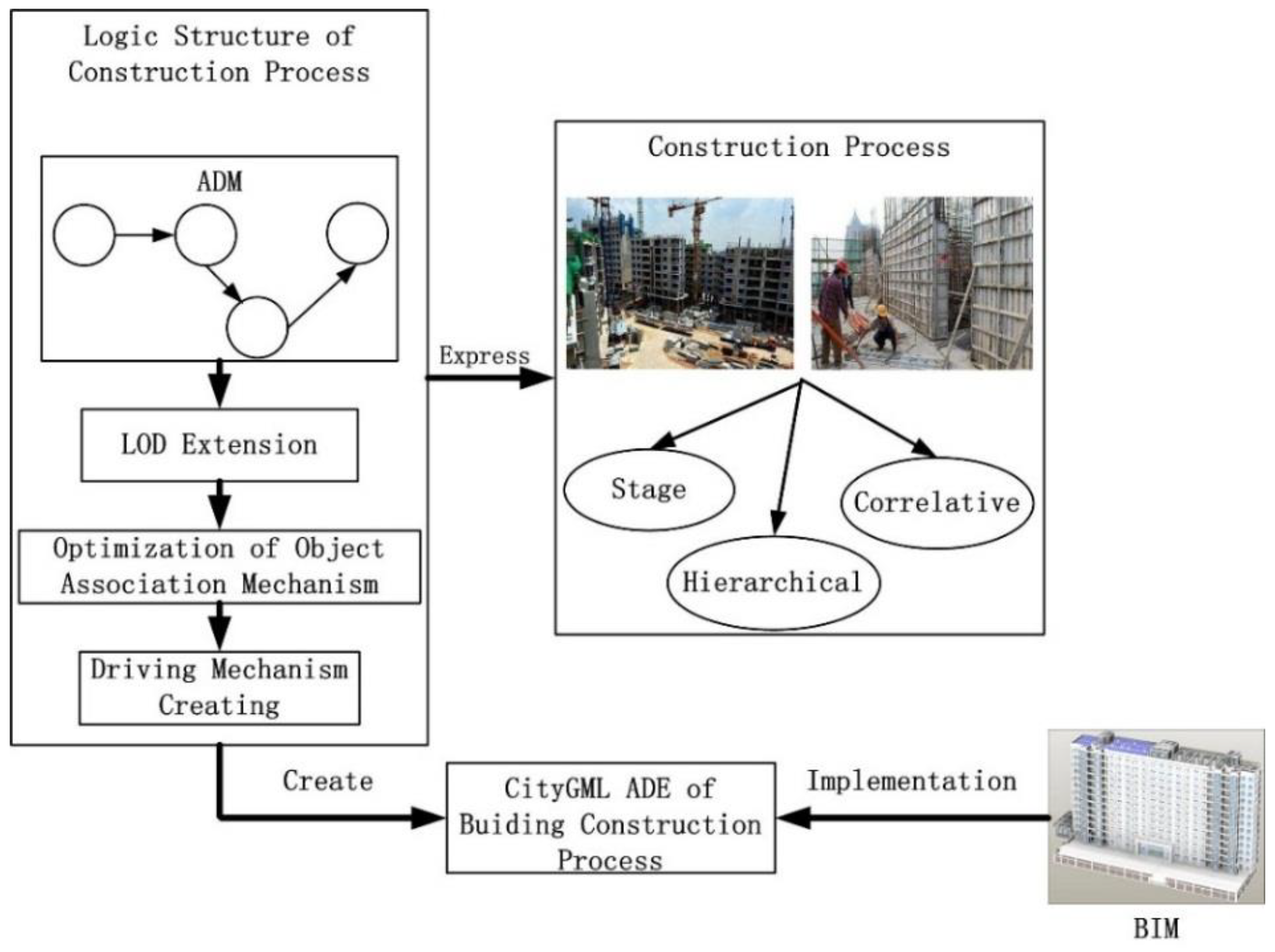
2. Research Framework and Scope

The construction process of a building obviously differs from the evolution process in nature in that it is a process that transforms nature under the leadership of human beings, with this transformation taking place in stages, and being hierarchical and correlative. Furthermore, differing from the construction process in the AEC field, the construction process at the city level involves a broad spatiotemporal scale and a larger amount of data. As the 4D model in AEC cannot accurately and efficiently express the building evolution process at the city level, the difficulty is finding a way to do this. Solving the problem, i.e., constructing a suitable model, requires solving the following problems, namely, the model must express the basic characteristics of the construction process, which are stage, hierarchy, and correlation. It must accurately express the building evolution processes at multiple spatiotemporal scales, and it must accurately express the behavior of the building objects, which are adding, removal, merging and change, during the evolution of the building.
In project management, the critical path method (CPM) [34] is used typically to represent a construction project. Among these methods are the arrow diagramming method (ADM) and the precedence diagram method (PDM), which can effectively represent each process and its corresponding relationships. The difference between these two methods is that ADM uses arrows to represent activities, whereas PDM uses nodes. In fact, they are similar in representing a construction project and one can be converted to the other. The construction activities are the driving forces of the building construction process. Considering that people are more accustomed to using arrows to represent the driving force of a certain process, this study chose ADM as the basic logic model to represent the building construction process.
Based on this, we organized the research framework in the following way. First, the characteristics of ADM that are commonly used in construction were analyzed to identify issues that needed further attention to represent the building construction process. Second, the identified issues were addressed, and an extended logical model was constructed to represent the construction process. Then, an extension for CityGML was developed based on the logical model. Finally, a BIM model was used as a data source to implement this ADE. Figure 2 illustrates the research framework.
The construction process of building projects is complicated and systematic. The process can be divided into different time periods based on the division of labor and materials, including foundation, framing, roofing, decoration, water supply and drainage, building electrical, intelligent building, and ventilation and air conditioning. The first four steps of the building construction process are related to the civil engineering stage that forms the core of the building project. It outlines the overall appearance of the building, and its construction process exhibits strong regularity. In addition, the overall appearance, which is an important aspect of the building, is very closely associated with the geographical environment. Therefore, in this study, the civil engineering stage of the building is selected to be the subject of research. However, information on resources required in the civil engineering stage, such as labor and funding, are not considered in this research.

3. Design of Building Construction Process ADE

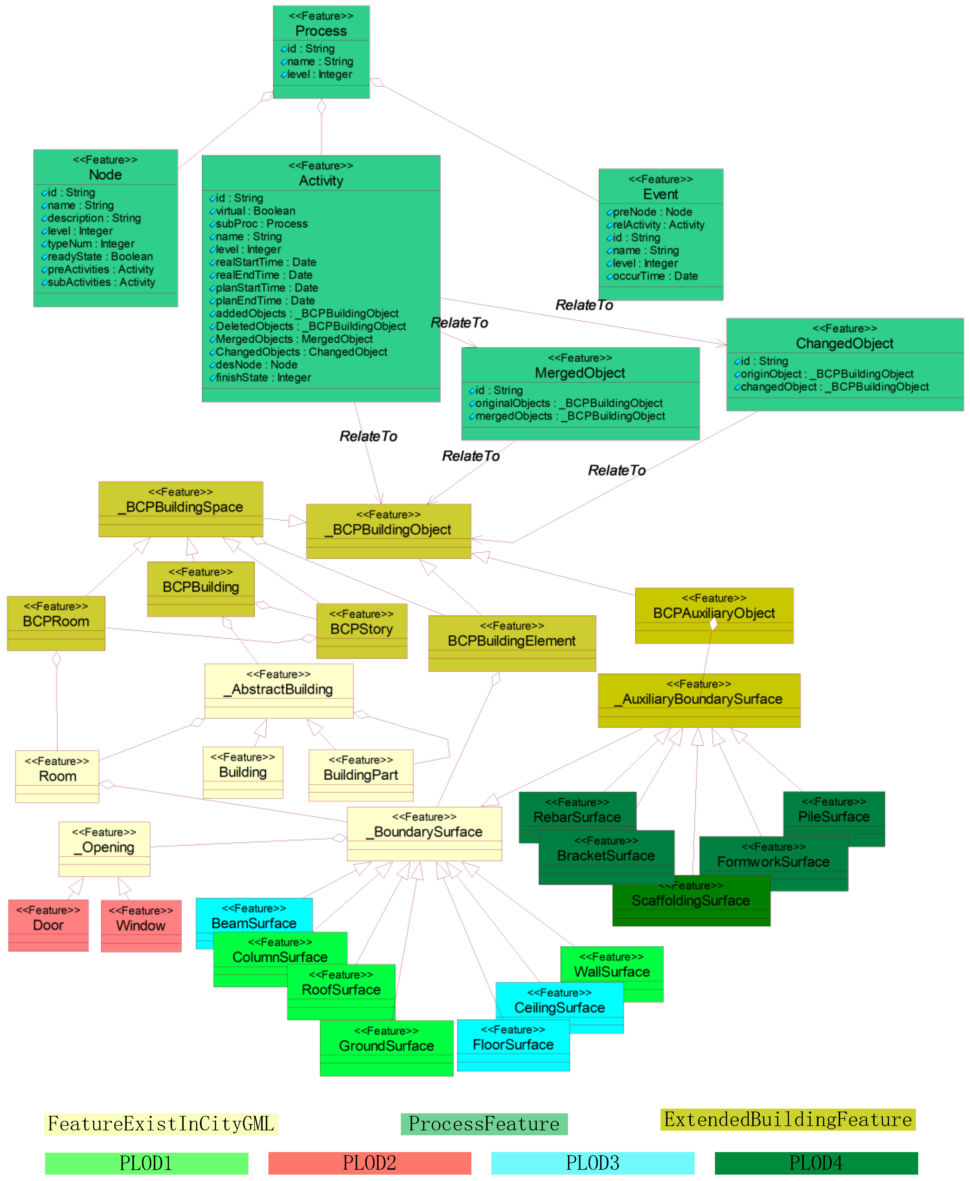
3.1. Characteristics Analysis of Basic ADM

The basic ADM (Figure 3) is used generally to represent the construction project with arrows and nodes. An arrow represents a construction activity that requires manpower and material resources. The left end of the arrow indicates the start of the construction activity and the right end indicates the end. A series of attributes, such as the job title and working time, can be attached to an arrow. The dashed arrow is a special type that does not represent an activity that requires time and resources but rather a logically restrictive relationship. For example, activity E in Figure 3 indicates that activity D can be performed only after activities B and C have been completed. A node is the connection point between arrows in an ADM. It indicates the time that work can be carried out after the pre-order work associated with a certain node had been completed. Nodes can be classified as starting, terminal, and intermediate. Starting and terminal nodes are unique within the model. The starting node represents the start of the entire process and the terminal node represents the end.
The ADM is suitable for representing the stage characteristics of a construction process (Figure 4). Each activity (arrow) has a corresponding relationship with each construction stage by associating two nodes of the model. The front node can represent the state of building objects when construction activity has not started, and the end node can represent the state after the activity has ended. The start and end of each activity precisely correspond to the continuous development of a construction process.
In addition, the ADM is suitable to represent the correlative characteristics of a construction process. For example, Figure 5 shows the pre- and post-constraints for the classic staged construction workflow. Activities a2 and b1 can be performed after a1 had been completed, whereas a3 can be performed after a2 had been completed. After a2 and b1 had been completed, b2 can be performed. Finally, b3 can be performed after a3 and b2 had been completed.
Although the ADM supports the stage and correlative characteristics of a construction process, some problems remain that must be eliminated. First, the ADM does not have hierarchical characteristics and cannot represent the construction process at multiple spatiotemporal scales. Second, the relation mode of the ADM to building objects must be defined that can express the behaviors of adding, removal, merging, and change of the building objects in the construction process. Third, the ADM only represents the construction plan; therefore, to represent the evolution process of construction, an extension is required for the flow mechanism so that the construction process can evolve automatically. Therefore, the ADM is extended as follows. First, the hierarchical characteristics are extended. On this basis, the association mode of the process and building objects is studied. Third, the driving mechanism is designed to automate the process. Finally, CityGML is extended to realize a building construction process ADE (BCPADE).

3.2. Extension of ADM

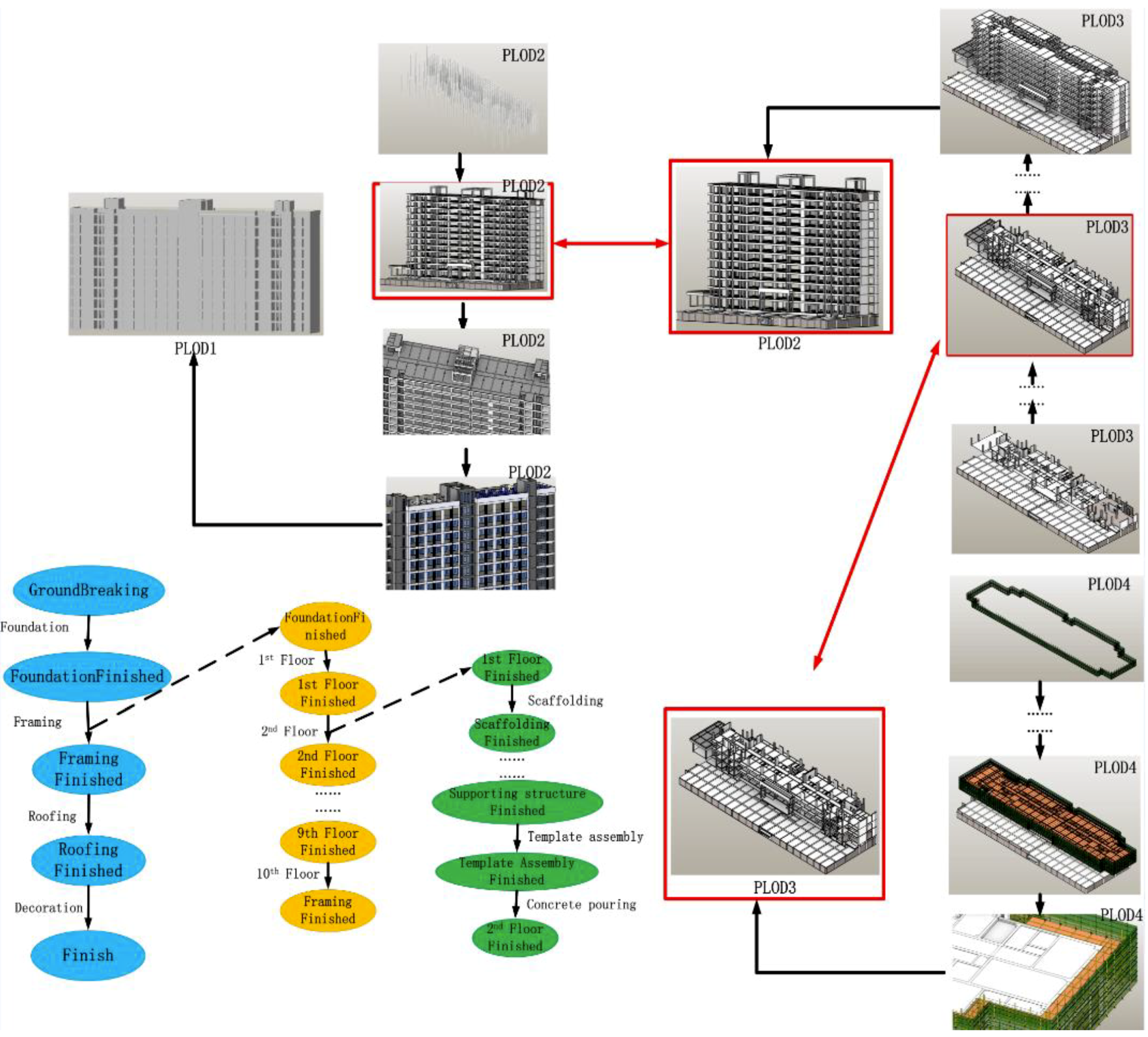
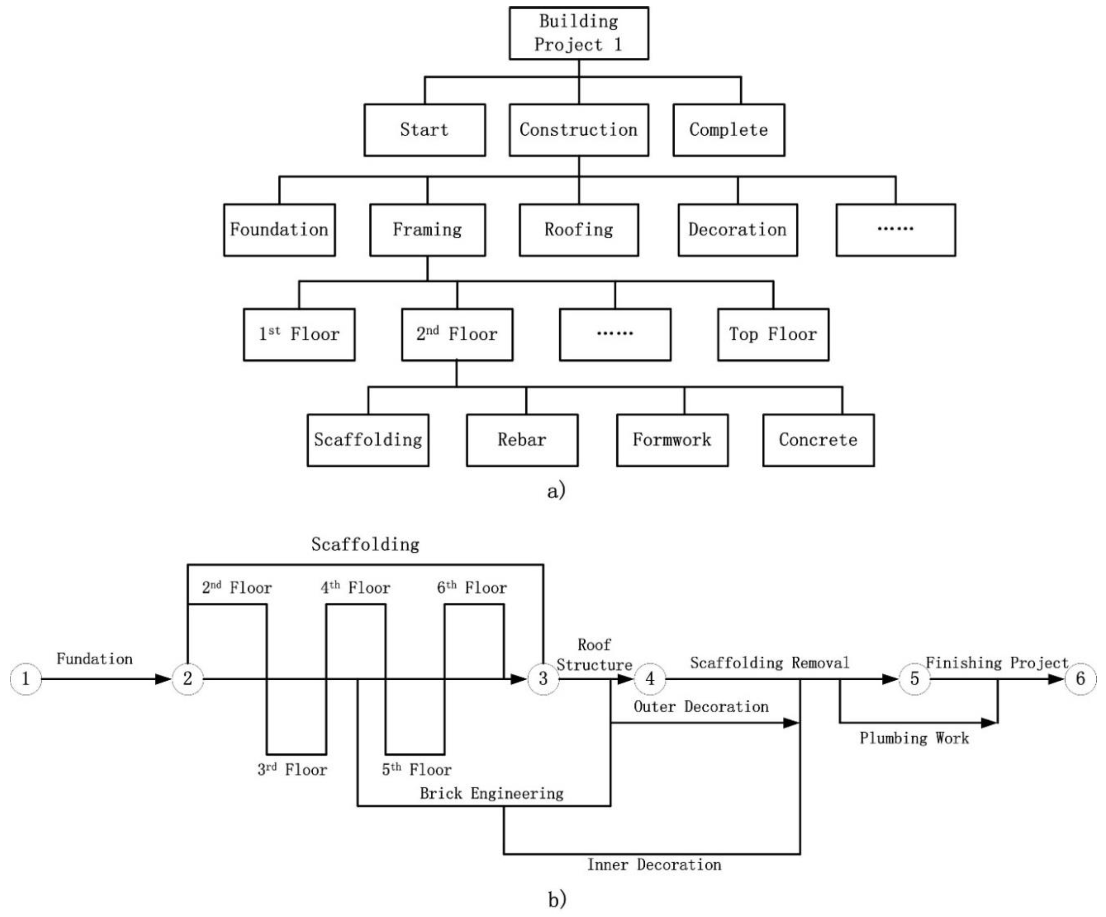
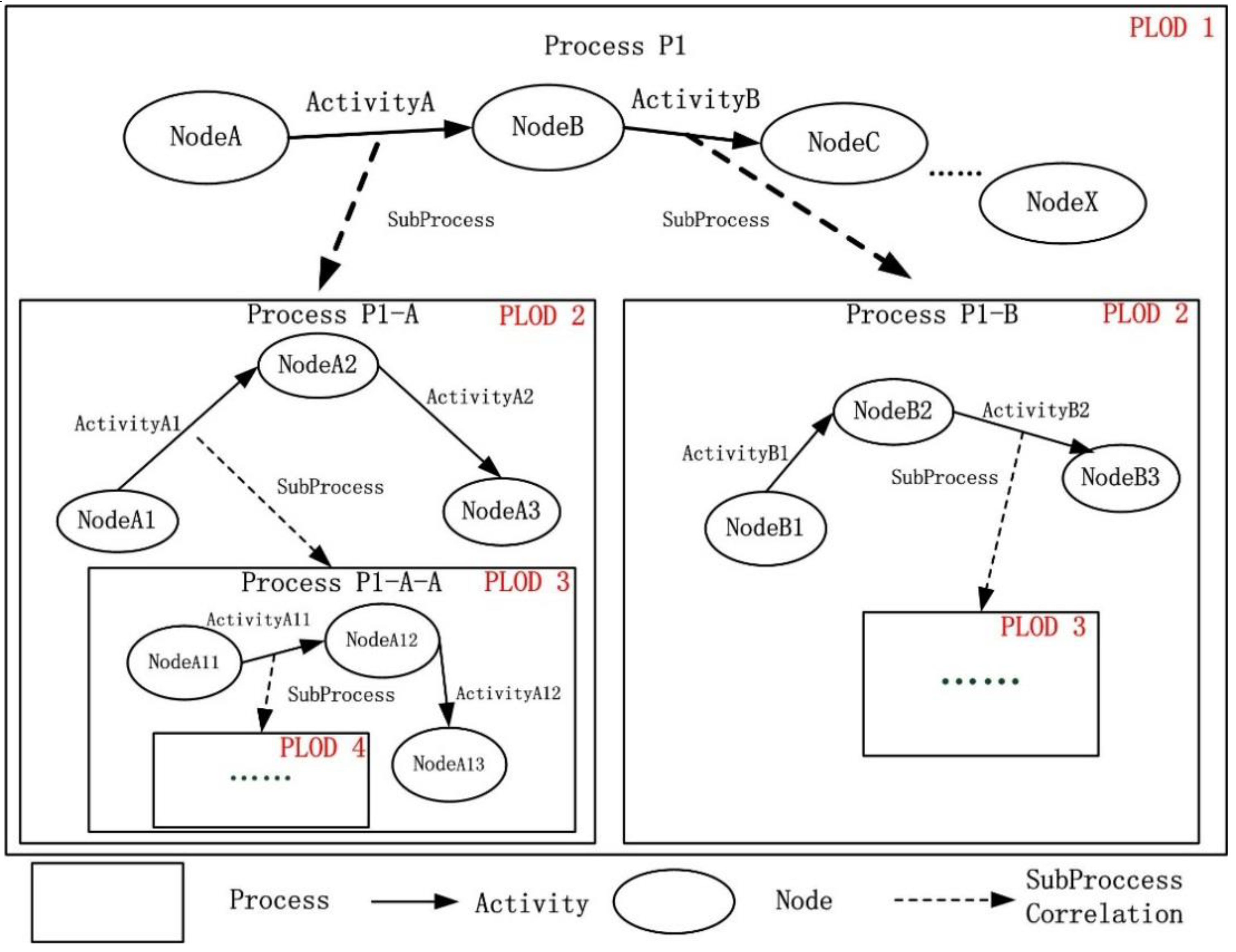
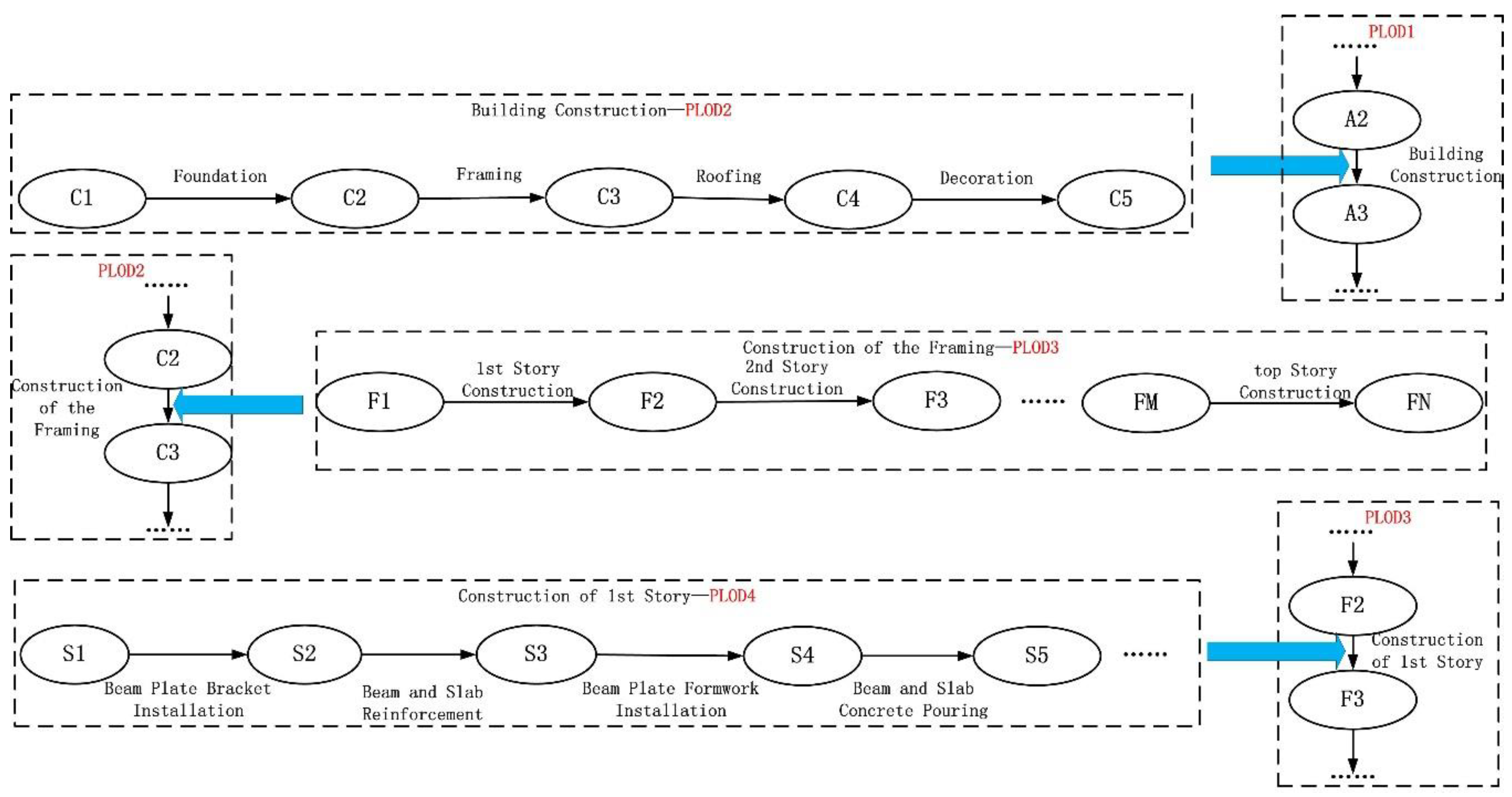
3.2.1. Hierarchical Extension of ADM

Objects at a distance from the user’s viewpoint are shown coarsely, whereas close objects are shown in a detailed representation [35]. Therefore, multi-resolution data can efficiently support the city-level process simulation. The LOD of the spatial data model play a significant role in numerous fields, e.g., CityGML uses the LOD model to express 3D city objects at different scales. With the support of the LOD model, a high-resolution visualization model for close-up observation can be provided. Similarly, at a considerable observation distance, the low-resolution model is used to optimize the amount of data in large scenes, thereby improving the efficiency of the data display in such large scenes.
Time and space have similar multi-resolution features. When an object must be observed continuously, the number of observations of the object will increase as the degree of attention increases, thereby shortening the observation interval and increasing the observation frequency. Observers with different degrees of interest will have different observation frequencies for the same object, resulting in different time scales.
Furthermore, there are different scales in the building evolution process at the city level. In the far perspective, the concern is with the evolution of multiple buildings in a large scene. The observation frequency of the single building evolution process is relatively low and results in a low time resolution. In a relatively close perspective, the evolution of the local part of the building can be seen. In this instance, the observation frequency of the single building evolution process is relatively high and results in a higher time resolution. If the same resolution is used to simulate the process model at different time scales, the efficiency of the model will be affected considerably. Therefore, the concept of LOD needs to be introduced to the spatiotemporal process at the city level, and a process levels of detail (PLOD) needs to be created for the building construction process.
The analysis presented in Section 1 shows the hierarchal characteristics in the construction process, and the PLOD can be defined based on these hierarchical characteristics. Different levels of focus produce different time resolutions for the construction process. Regarding urban planning managers, their focus is on the start, construction, and completion of the building, which can be seen as the most coarse-grained level of detail in the construction process. Regarding the leadership of the construction company, their task is to coordinate the various divisional projects, including foundation, framing, roofing, decoration, and other details. To execute the construction tasks of each of the above divisional projects, the principals of the various departments of the construction company need to formulate their own construction procedures for each divisional project. For example, the construction of the framing can be refined into the successive construction procedures of the structure of each story. The construction of the structure of each story can be refined further into detailed construction activities, such as the installation of scaffolding, binding of steel bars, installation of formwork, pouring of concrete, and the like.
Based on the above analysis, we proposed a PLOD hierarchy for the building construction process, including four levels of details. These are:
PLOD1: Pay attention to the beginning and end of the project, and not to the intermediate process, i.e., it can only express the start and the end of the project. At this level, the overall outline of the building can be seen, but not the details such as doors and windows.
PLOD2: Pay attention to the divisional projects, i.e., it can express the divisional projects of the building construction, including foundation, framing, roofing, decoration stage, etc. At this level, the facade can be seen, as well as the detail of the building elements on the façade such as doors and windows.
PLOD3: Pay attention to each procedure in the divisional project, e.g., the construction of framing can be refined to the construction of each story. At this level, the construction process of each story can be expressed and the building elements inside the stories can be seen.
PLOD4: Pay attention to the construction process in each procedure. At this level, the construction details of the relevant building elements can be seen, such as the installation of formwork for beams.
An example of the hierarchical structure for PLOD1, LODP2, PLOD3, and PLOD4 is shown in Figure 6.
The PLOD model characterizes the characteristics of the different levels of the construction process and forms a hierarchy that combines local construction changes with overall construction changes. It forms the basic time scale of four different levels of detail in the construction process.
Based on the above analysis, the ADM model was extended hierarchically, as follows.
  • The process model was divided according to different time scales and has a hierarchical structure.
  • Objects such as activities and nodes were based on a specific time scale. Objects at a lower level can be aggregated into a higher level.
Objects at a higher level have coarser granularity and are more macroscopic, whereas objects at lower levels have finer granularity and are more microscopic. The higher and lower levels of the model are related by activities, i.e., activities at a higher level can correspond to a lower-level process. With further division, more microscopic activities and nodes can be added to a process. For example, Figure 7 shows that ActivityA in the higher-level process P1 can be related to sub-process P1-A, and activity ActivityA1 in sub-process P1-A can be related to sub-process P1-A-A. The activities in the sub-sub-processes can be iterated further.

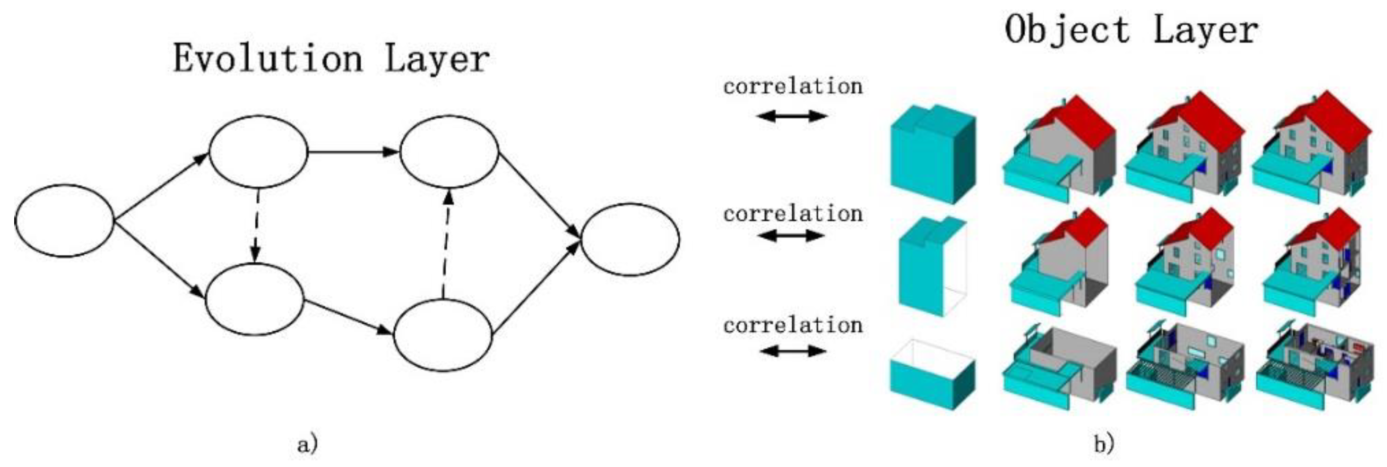
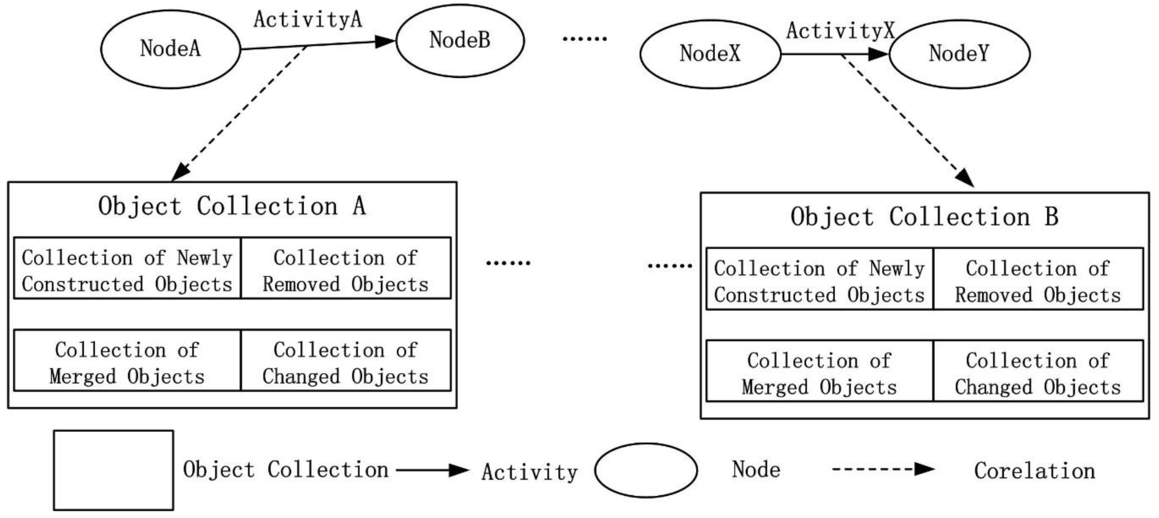
3.2.2. Association of the Construction Process and Building Objects

Building objects play an important role in the construction process. They comprise building elements such as walls, columns, beams, and floors, and building spaces such as buildings, stories, and rooms. The building objects need to be related to the construction process itself to simulate the evolution process of construction. The associating of building objects with the construction process is done in the following way. The model is divided into two layers, namely evolution and object. The evolution layer mainly describes the corresponding stages of the construction process and their relationships. The object layer mainly describes the building objects associated with the construction process (Figure 8).
A problem that needs solving is how to relate the building objects to the construction process. Two principal issues must be solved, namely (1) whether to use a node or activity to associate building objects, and (2) how to express the evolutionary behavior of the building objects during the evolution process.
Regarding the first issue, it must be considered that in an ADM, each construction activity corresponds to a change in the building objects in a one-to-one relationship. However, each node may have more than one pre-order activity, which means that a node and the alteration of building objects may not have a one-to-one relationship. For example, node 5 in Figure 5 corresponds to two pre-order activities, a3 and b2, and the alteration of building objects may, therefore, be related to a3 and b2. Therefore, we should use activities to associate building objects.
Regarding the second issue, analysis of the behaviors of building objects in the process of building evolution indicates that the following four behaviors generally exist in the process of building construction [36]:
  • Newly constructed, which are objects newly constructed in an activity (e.g., newly constructed building elements such as walls, doors, and windows).
  • Removed, which are objects removed from the building in an activity (e.g., removal of the formwork after the concrete is poured).
  • Merged, which are objects merged into other new objects in an activity (e.g., in the construction of stairs, side beams, steps, handrails, and railings are merged into flights of stairs).
  • Changed, which refers to the alteration of the geometry, position, or attribute information of the objects in an activity (e.g., the color of the wall changed after being painted, or the position of the building elements changed after being moved).
Therefore, when information on the amount of change in a building object is being saved, the above four behaviors must be considered and the corresponding dataset must be maintained (Figure 9).
The PLOD model we proposed defines different time scales for the construction process. At the same time, CityGML developed five LODs for city objects at different scales. Therefore, under the basic process/object association framework described above, it is necessary to consider the association between different PLODs and the original LODs in CityGML.
According to the definition of PLOD, PLOD1 is the coarsest level of detail in the construction process, focusing on the overall changes of the building, the detail building elements (such as windows and doors) cannot be identified at this level. Therefore, the building objects associated with this level best match the LOD2 in CityGML. PLOD2 is finer than PLOD1 and can be refined to the outer facade of each building story. The building elements such as doors and windows on the façade can be seen in this level. Therefore, the building objects associated with this level are most consistent with LOD3 in CityGML. PLOD3 is refined into the construction process inside each story, and all the building elements inside the building can be recognized at this level. Therefore, the building objects of PLOD3 correspond to LOD4 in CityGML. PLOD4 is the finest detail level in the construction process, involving the manufacturing process of building elements. For example, when a reinforced concrete structure is constructed, a joint cast-in process of columns, beams, slabs, and the like is performed. This level is finer than LOD4 of CityGML and requires further extension. A summary of the correspondence between the building objects involved in the PLOD model and the LOD model in CityGML is displayed in Table 1.

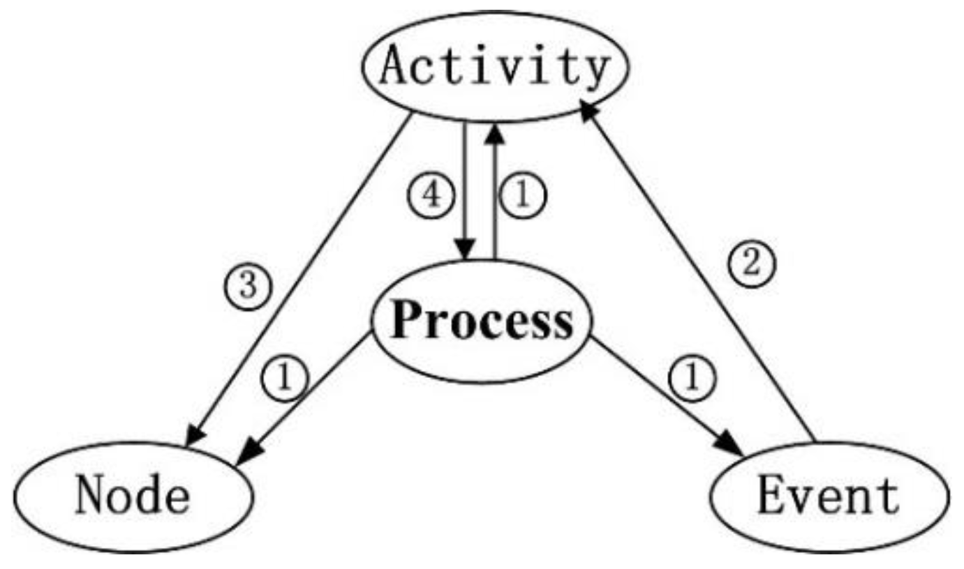
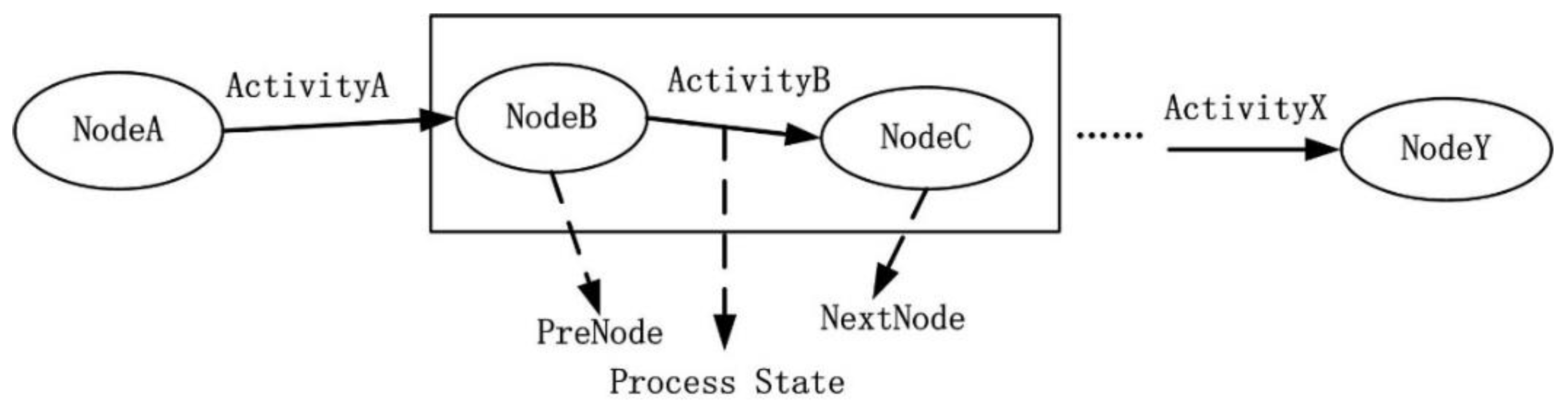
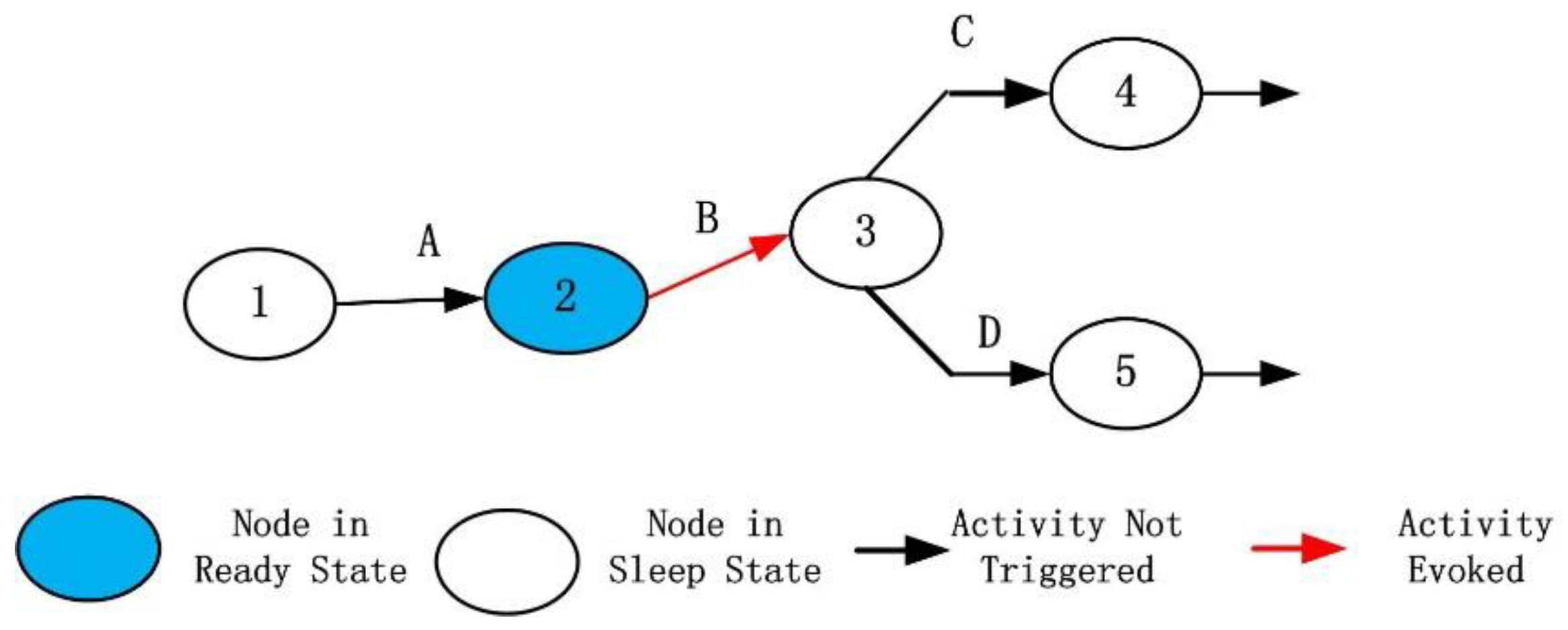
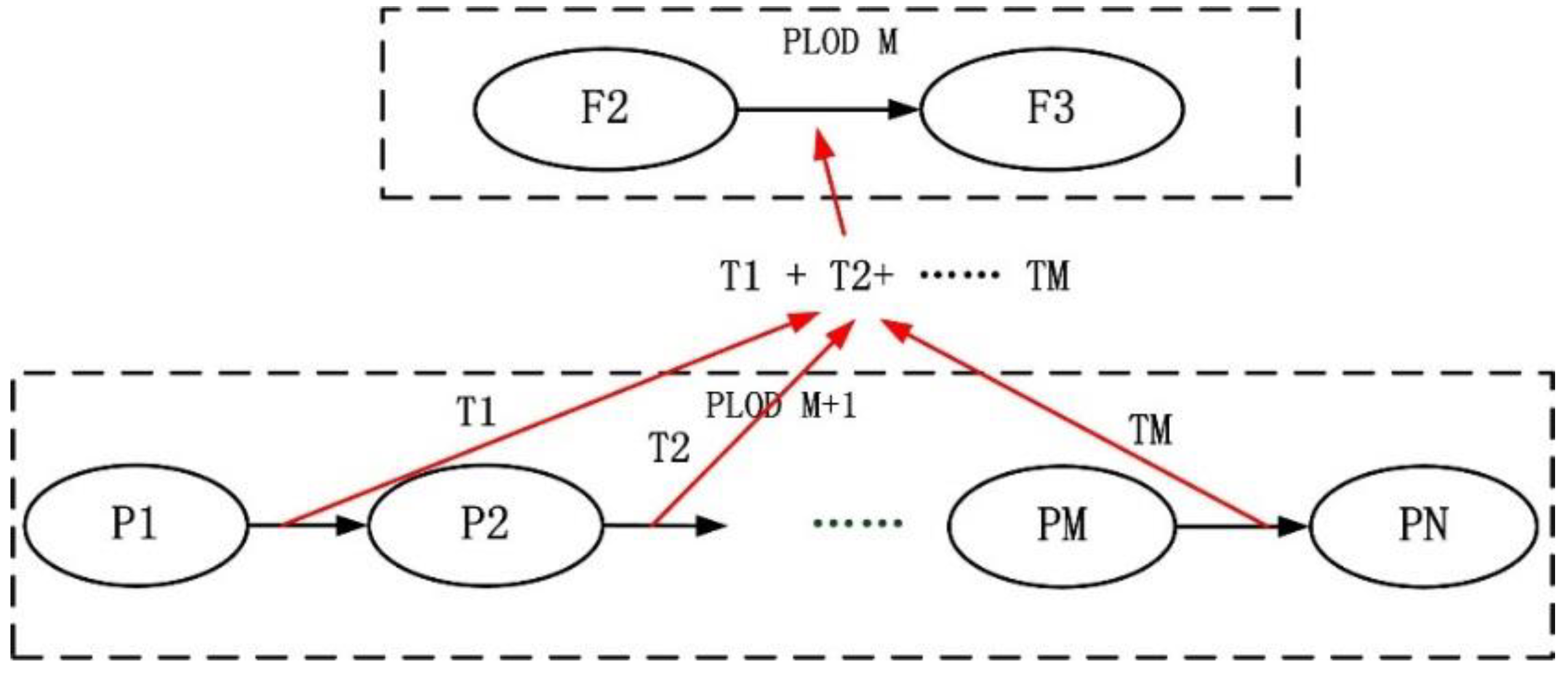
3.2.3. Driving Mechanism of the Model

A driving mechanism needs to be introduced to the model to simulate the construction process, which requires a further extension of the model and a definition of the flow rules.
a) Further Extension for the Driving Mechanism
The current model has four major parts, namely process, node, activity, and associated building object. To simulate dynamic changes in the construction process, objects that trigger the process flow of the model need to be introduced. Considering that, during the construction process, each activity is triggered by a certain event, an event object can be added to the model to trigger the automatic flow of the model. Consequently, the model eventually consists of five elements, which are process, activity, node, event, and building object. The relationships between the process, activity, node, and event are defined as follows (Figure 10).
  • A process consists of activities, nodes, and events.
  • An activity can be triggered by an event.
  • The state of a node can be changed by an activity.
  • An activity can be associated with the sub-processes of the next level.
b) Evolution Rule of the Construction Process Model
During the construction process, often subsequent activities cannot be started because the pre-order activities have not been completed yet. To represent this situation, the following restrictions were added to the model. First, a node can have one of two states, namely ready and sleep (Figure 11). When all pre-order activities of a single node have been completed or the node has no pre-order activities and the subsequent activities have not all started yet, the node is in the ready state. When some or all of the pre-order activities of the node have not been completed, the node is in the sleep state. When all subsequent activities of the node have started, the node returns to the sleep state.
Second, the subsequent activities of a certain node can be triggered only when the related node is in the ready state. This ensures that if the pre-order activities have not been completed, the subsequent activities do not meet the starting conditions and can only be triggered when the pre-order activities have been completed. For example, in Figure 12, as node 2 is in the ready state, the subsequent activity B can be triggered by an event. As node 3 is in the sleep state, the subsequent activities 4 and 5 cannot be triggered by an event. As the subsequent activity A has been completed, node 1 has returned to sleep and activity A will not start again later.
c) Driving Algorithm of the Process Model
The driving algorithm of the process model is as follows.
  • Initialization.
  • Wait for an event to trigger before going to the next step.
  • Look for an associated activity A and the associated pre-node N of this event. If node N is not in the ready state, end the process and return to Step 2. Otherwise, go to the next step.
  • For node N, find the subsequent activities and ascertain whether they are all running or finished. If they are finished, set N to the sleep state.
  • Start the activity. When the activity ends, proceed with the next step.
  • Find the subsequent node of the activity. For the found node M, find all pre-order activities to ascertain whether they have all finished. If so, set M to the ready state and go to the next step. Otherwise, return to Step 2.
  • Determine whether subsequent virtual activities are associated with M. If so, launch the virtual activity directly. If no subsequent non-virtual activities are associated with M, set it to the sleep state. For each virtual activity, proceed with Step 6.
  • Return to Step 2.
As an example, Figure 13 shows a fragment of a construction process. At the start, the pre-order activities of nodes 1 and 3 are assumed to have been completed, and they are in the ready state (Figure 13a). Once an event triggers activity A to start, node 1 goes to sleep. Next, when activity A is complete, the subsequent node 2 is in the ready state, and the subsequent virtual activity is automatically triggered. When the virtual activity after node 2 is triggered, node 2 returns to the sleep state (Figure 13b). An event then triggers activity B to start, and node 3 changes from the ready state to the sleep state (Figure 13c). Next, when activity B is complete and the pre-order activities of node 4 are all complete, node 4 transits to the ready state (Figure 13d). After the start of activity C, node 4 is still in the ready state because the subsequent activity D of node 4 has not yet started (Figure 13e). Finally, activity C is complete and node 5 transits to the ready state. Then, node 4 changes to the sleep state after activity D starts (Figure 13f).

3.3. Building Construction Process ADE

Figure 14 shows a Unified Modeling Language (UML) diagram that represents the BCPADE in CityGML. The diagram is divided into two parts, namely the construction process model and the building model. This is an extension of the original building data model of CityGML. The original model does not include structural elements in the construction process, thus, the extension includes structural elements such as columns and beams. When the building is under construction, objects such as rebar, bracket, formwork, and scaffolding are closely related to the building construction process, they are also added to the original model as the auxiliary objects. The classes BCPBuildingElement and BCPAuxiliaryObject have been newly created to correlate all _BoundarySurface and _AuxiliaryBoundarySurface (newly created as the subclass of _BoundarySurface for auxiliary objects) objects in CityGML for association with the building construction process.
We created a new class _BCPBuildingSpace to correlate the building objects that contain a space, which are the super classes BCPBuilding and BCPRoom. Considering that buildings are organized predominantly by stories, the class BCPStory was added to the building data model, which is also the subclass of _BCPBuildingSpace.
In addition, we created class _BCPBuildingObject as the super class of _BCPBuildingSpace and BCPBuildingElement, used to correlate directly with the construction process in a uniform manner. To maintain the hierarchical relationship of the original classes in CityGML, the newly created classes BCPRoom, BCPStory, and BCPBuilding were used to derive the class _BCPBuildingSpace, and the original classes Room and _AbstractBuilding in CityGML are aggregated by them.
A process consists of three elements, namely nodes, events, and activities and they have common attributes such as the id (unique number of an object), name (base name of the object), and level (basic spatiotemporal hierarchy to which the object belongs). Activities at a higher level can be associated further with lower-level processes, which also comprise objects such as events, nodes, and activities.
In addition to the above common attributes, each object has its own specific attributes. For nodes, typeNum indicates whether a node is the starting node (value 1), the intermediate node (value 2), or the terminal node (value 3) of the construction process. The description presents the basic information of a node. The readyState of a node can be 0 (ready) or 1 (sleep), which is a key attribute that constrains the relationship between nodes and activities. The alteration of the state of a node is determined by the pre-order and subsequent activities. At the same time, it also determines whether the subsequent activities of the node can be triggered by corresponding events. Finally, preActivities associates the node with pre-order activities, whereas subActivities associates the node with subsequent activities.
Activities are transition objects. First, they link the process model and building objects. They relate to four object-change types, namely added, removed, merged, and changed. Second, the subProc attribute allows an activity to be associated with a lower-level construction spatiotemporal process. The virtual attribute indicates whether an activity is real or simply represents a constraint between nodes and activities. Because each activity of a construction process is related closely to time, time is an important attribute and can be divided into planned and actual types. Finally, the attribute desNode associates the activity with a subsequent node, and the attribute finishState has three values for a started activity, which are 0 (sleep), 1 (running), and 2 (finished).
Events are the driving force for the entire construction process and are associated with the previous node by the preNode attribute. After an event occurs, if the relevant node is in the ready state, a relevant activity denoted by the relActivity attribute is started to facilitate the flow of the construction process. In addition, an event contains an occrTime attribute that identifies when it occurs.

4. Implementation of the Model
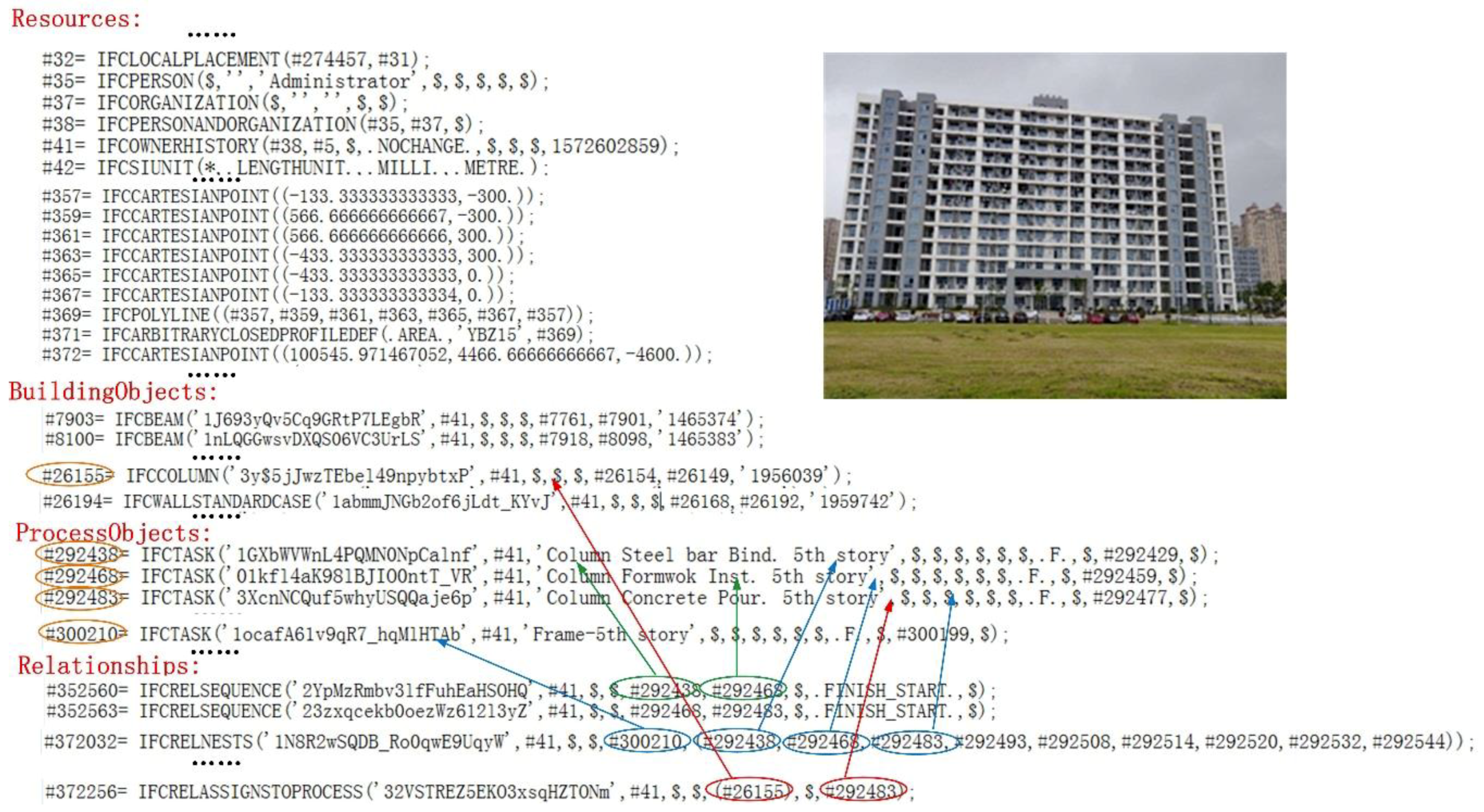
4.1. Research Data

In this study, the model was implemented through a semi-manual transformation. We selected the construction process data of the youth teachers’ apartment building of Nantong University (Figure 15) and stored the data in the BIM model. These data represent the entire evolution of the building, including the processes of building construction and the sequence of activities in the process. The IFC model was used to organize the data, and as shown in Figure 15, the data can be divided into four parts. The first part contains the resources that constitute the building objects, including coordinates, directions, polylines, owner histories, placements, etc. The second part contains the building objects, such as beams, columns, and walls. The third part contains the process objects; these are mainly IfcTask (a subclass of IfcProcess) and IfcProcess, which represent construction activities and processes. The fourth part contains the relationship objects; among them are the IfcRelSequence (used to express the sequence between activities), the IfcRelAssignsToProcess (used to associate building objects with process objects), and the IfcRelNests (used to relate the activities to a process).
As shown in Figure 15, the object with number #352560 is IfcRelSequence, which is associated with the activities with numbers #292438 and #292468. Moreover, it limits the activity with number #292468 in such a way that it can only be started after the activity with number #292438 has been completed. The object of number #372032 is IfcRelNests, which associates activities with the numbers #292438, #292468, #292483, etc. to the IfcTask with number #300210; in this way, it establishes an association between the process and its related activities. The object numbered #372256 is IfcRelAssignsToProcess, which associates the IfcColumn with number #26155 to the IfcTask with number #292483. Through this kind of data organization, building objects and process objects are organized as a whole.
As seen from the figure below, the construction activities are mainly involved in the PLOD4 level, such as column steel bar binding, column formwork installation, and column concrete pouring.

4.2. Method and Results

There are two challenges to generating BCPADE from the IFC data. The first is how to establish a mapping relationship from IFC to BCPADE to realize the conversion of the process model between them. For this problem, we can establish the mapping from IFC’s building objects, relational objects, and process objects to the building objects and process objects in BCPADE; especially, the arrow diagram is an important part of BCPADE, which should also be created. Because the objects in the data file belong to the PLOD4 level, the PLOD4 level of BCPADE can be created after solving the problem. The second involves building the PLOD model of BCPADE based on the solution to the first problem. For this problem, we can start from the building objects and process objects in the PLOD4 level and simplify them to PLOD3, PLOD2, and PLOD1, in a step-wise manner. After solving the two abovementioned problems, the method described in Section 3.2.3 can be used to achieve an automatic flow of the model. The specific steps to generating BCPADE from the IFC data are shown in Figure 16.

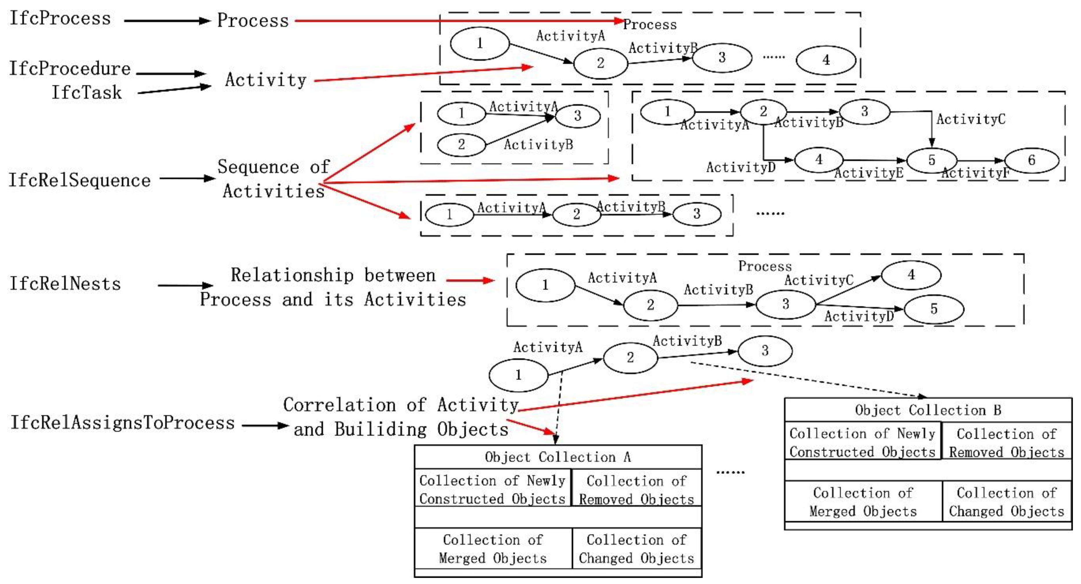
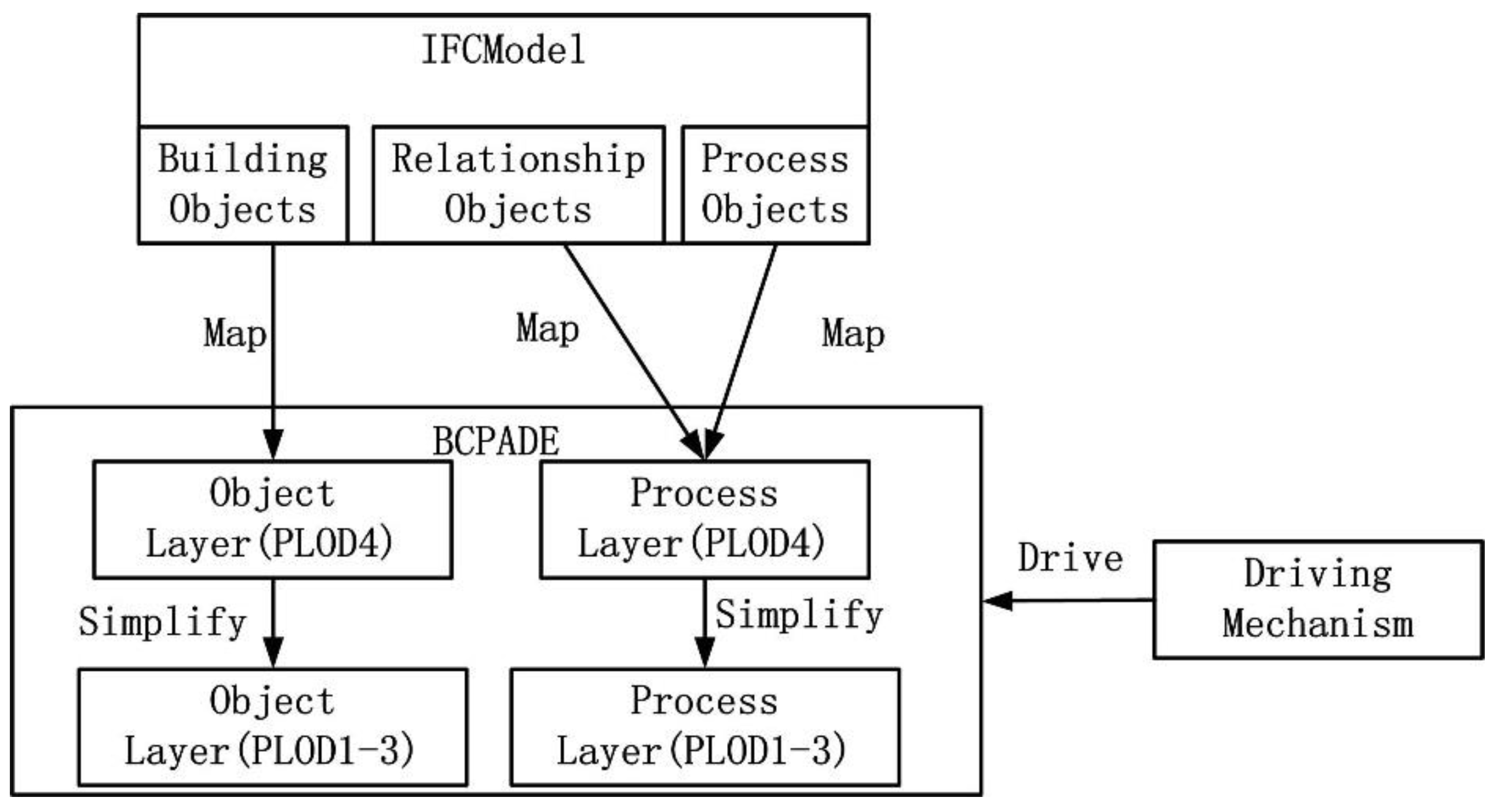
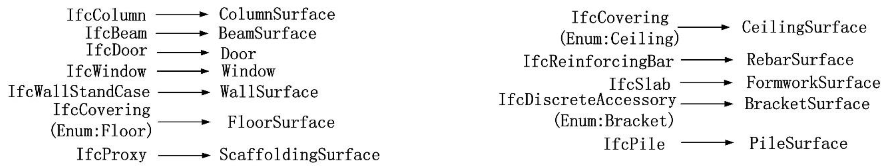
4.2.1. Establishment of Basic Mapping Relationship

IFC defines IfcProcess as its process object to express the construction process in the AEC field. On this basis, IfcTask and IfcProcedure are defined to express the construction activities in a process. IfcProcess and its activities are related to the relationship of IfcRelNests. The relationship IfcRelSequence is defined in IFC to express the relationships (such as parallel, serial, and the like) between the activities. In addition, the relationship of IfcRelAssignsToProcess is defined to enable building objects to be associated with IfcProcess (Figure 17).
Comparing BCPADE and the process model of IFC shows parallels between the two process models. IfcProcess can be mapped from IFC to a process in BCPADE. IfcProcedure or IfcTask can be mapped from IFC to activity in BCPADE. The relationship IfcRelNests can be used to establish the nested relationship between process and activities in BCPADE. The relationship IfcRelSequnce can be used to derive the sequence between activities in BCPADE. The relationship IfcRelAssignsToProcess can be used to establish the associations between an activity and its corresponding building objects in BCPADE.
Based on the above analysis, the relationship between IFC and BCPADE was created to realize the conversion between them. The process, procedure, task, and relationship objects in the IFC process model were mapped to the corresponding objects in BCPADE. Figure 18 shows the detailed mapping between IFC and BCPADE.
Based on the above mapping, the detailed conversion steps are as follows.
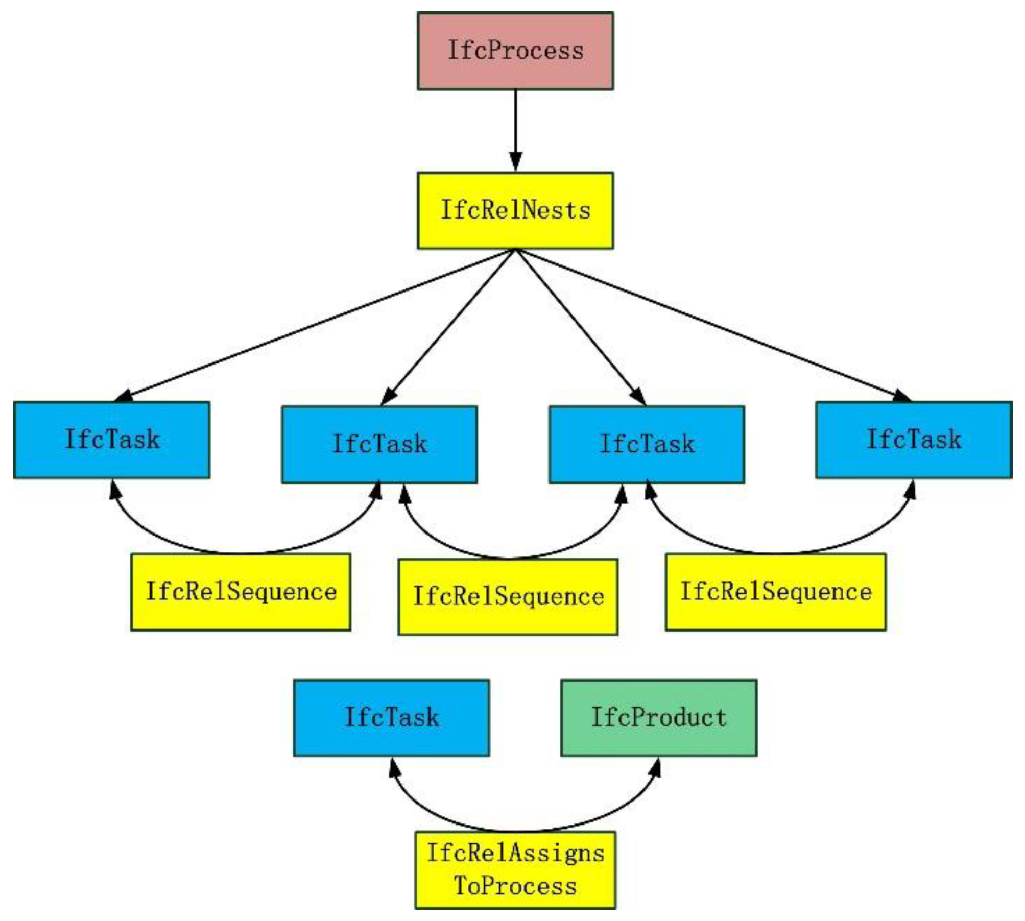
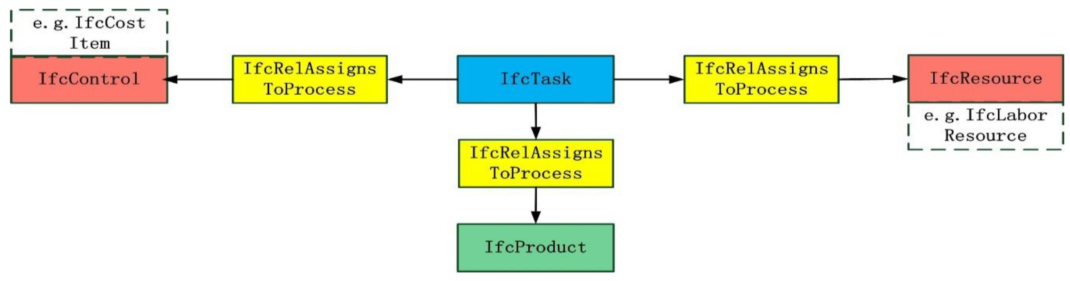
  • Find all the process objects of IfcProcess in the data file and map them to processes in BCPADE. Find all the process objects of IfcTask in the data file and map them to activities in BCPADE.
  • Find all the relationship objects of IfcRelSequence in the data file. Relevant activities can be obtained from the RelatingProcess and RelatedProcess attributes of each relationship, and sequence relationships of the activities can be established accordingly.
  • Find all the relationship objects of IfcRelNests in the data file and establish the association between each process (related to the attribute of RelatingObject in the relationship) and the corresponding activities (related to the attribute of RelatedObjects in the relationship) in BCPADE according to each relationship.
  • Find all the relationship objects of IfcRelAssignsToProcess in the data file and the association relationship between each activity (related to the attribute of RelatingProcess in the relationship) and its corresponding building objects (related to the attribute of RelatedObjects in the relationship) according to each relationship.
After performing the aforementioned steps, the relationship between each process and its activities, relationship between each activity and its corresponding building objects as well as the sequence relationships between the activities can be established. Based on this, the arrow diagram in BCPADE can be derived from the sequence relationships between the activities obtained in step 2 above. The algorithm is described as follows:
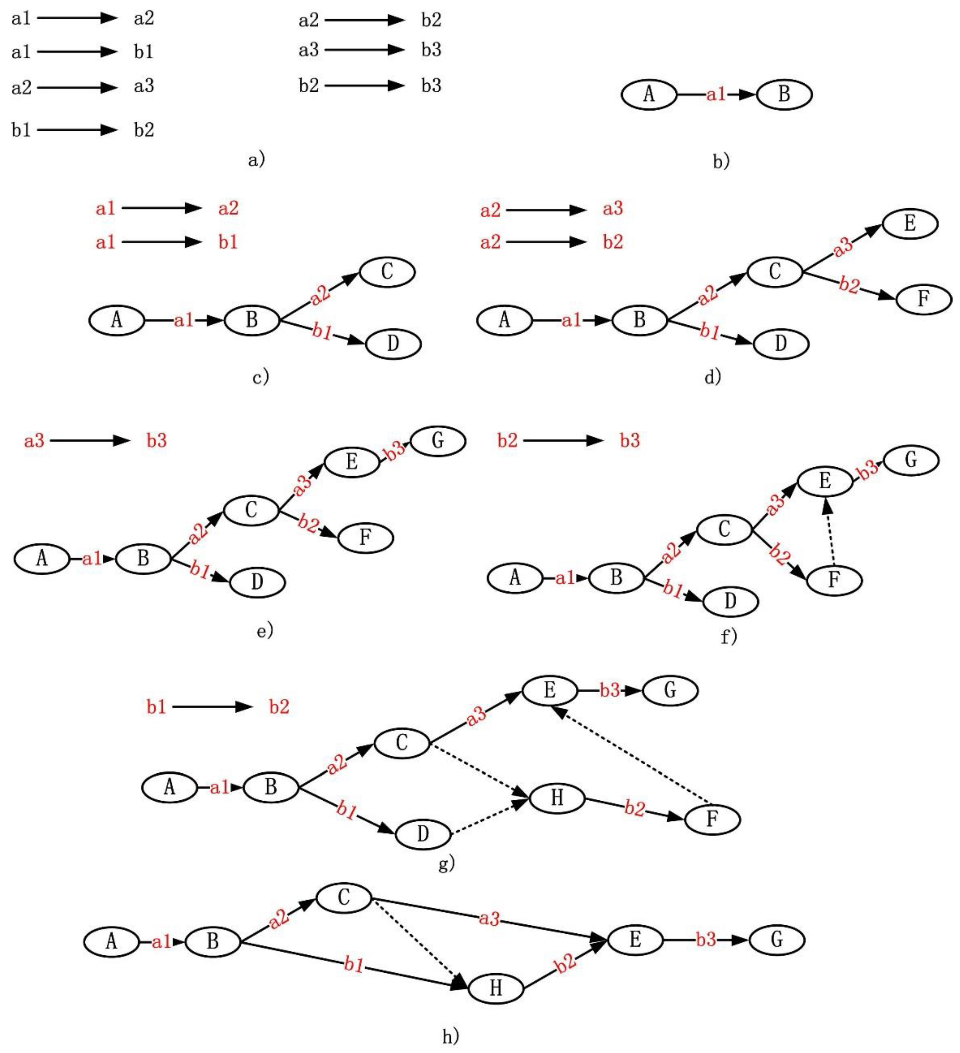
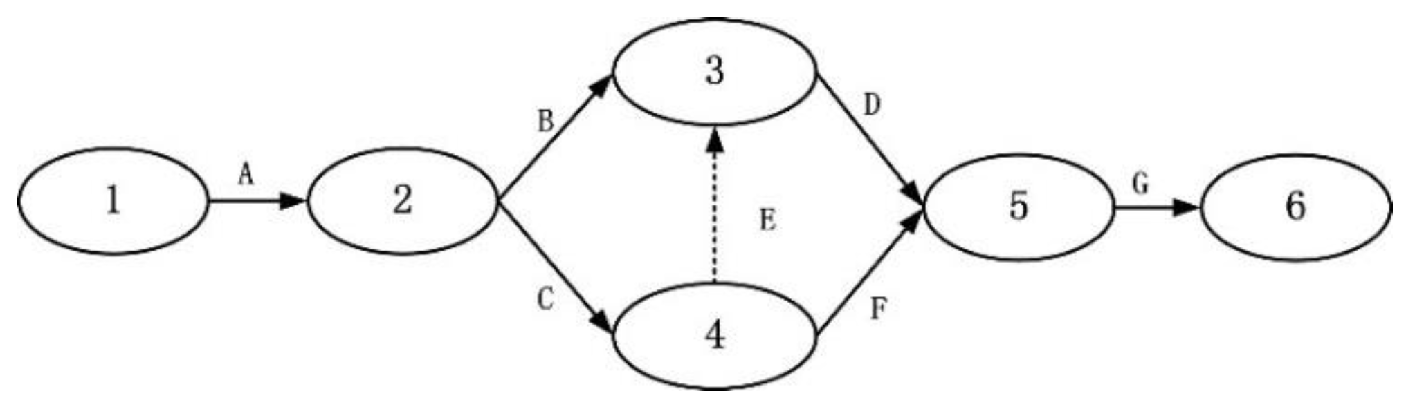
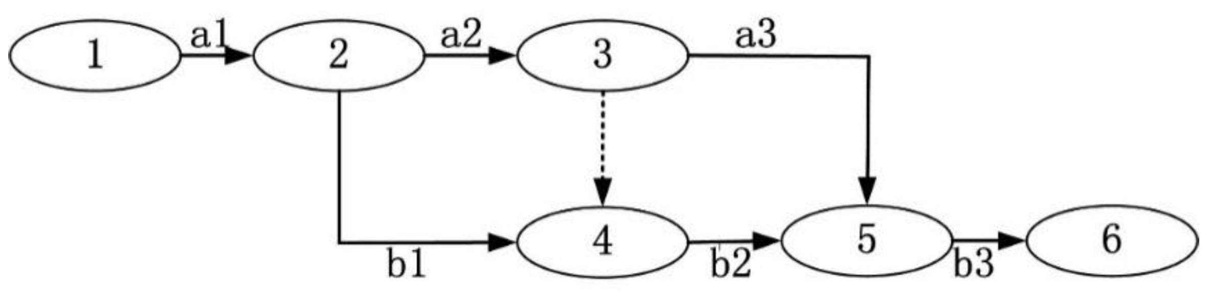
  • Algorithm Name: Derive_Arrow_Diagram
  • Input: The set of the activities named Activity (derived by step 1); the set of the sequence relationships between the activities named Seq (derived by step 2).
  • Auxiliary data structures: The set of the nodes named Node, set of the relationships of the node and its subsequent activity named Node_Activity, and set of the relationships of the activity and its subsequent node named Activity_Node.
  • Output: Node, Node_Activity, Activity_Node and Activity.
The reusable operations in the algorithm are as follows: (1) Create a new node: create a node in the set of Node; (2) Link the activity A between nodes N and M: Add a data pair to the set of Node_Activity. The first item of the data pair is N and the second is A. Add a data pair to the set of Activity_Node. The first item of the data pair is A and the second is M. (3) Create a virtual activity: create a virtual activity in the set of Activity. (4) Delete a node: delete a specific node in the set of Node and delete its references in the sets of Node_Activity and Activity_Node. (5) Delete an activity: Delete a specific activity in the set of Activity.
  • Initialization: The sets of Node, Node_Activity, and Activity_Node are all set to empty.
Algorithm flow:
  • Create an initial node N_0.
  • Traverse all the sequence relationships in Seq and find the starting activity A (the only activity in each process that has no pre-order activity), create a new node N_a, and link the activity A between N_0 and N_A.
  • Set the activity A and node N_A as the parameter and call the subroutine from step 4.
  • Subroutine: Create a sub_diagram with a certain activity as the starting activity (parameters: P, starting activity; N_Q, the subsequent node of P)
    (1) Create a set P_Next. Traverse all the sequence relationships in Seq to find all the subsequent activities of P and store them in P_Next.
    (2) For each activity Q in P_Next, perform the following operations:
      a) If the activity Q is not contained in the current diagram (there is no reference to Q in the set of Node_Activity), create a new node N_Q_Next, and link the activity Q between N_Q and N_Q_Next.
      b) If the activity Q is contained in the current diagram (there is one reference to Q in the set of Node_Activity), it means that the pre-order node of Q has been added to the diagram, and further operations need to be performed according to the situation as follows:
      i)
    If there are no other subsequent activities for Q’s pre-order node N_Q_Pre, create a virtual activity VA0 and link it between N_Q and N_Q_Pre.
      ii)
    If there are other subsequent activities for Q’s pre-order node N_Q_Pre, create a new node N_Mid and a virtual activity VA1. VA1 is linked between N_Q_Pre and N_Mid; Q is linked between N_Mid and Q’s subsequent node. Create a virtual activity VA2 and link it between N_Q and N_Mid.
    (3) For each activity Q in P_Next, recursively call the subroutine in step 4 to create a sub_diagram with this activity as the starting activity, and the parameters passed are the node Q and Q’s subsequent node N_Q_Next.
  • Simplify the diagram under the following situation: (1) There are three consecutive nodes in the order X, Y, and Z. (2) The middle node Y has only one pre-order activity and one subsequent activity and one of the two activities is a virtual activity. (3) X is not the pre_order node of Z. The specific steps of the simplification are as follows: (1) Delete the intermediate node Y and the virtual activity. (2) Link the other non-virtual activity L between X and Z.
Figure 19 is an example of the steps for creating an arrow diagram. The original sequence relationships of the original activity are shown in Figure 19a. From the relationships, we can find the initial activity a1. Therefore, nodes A and B are created, and a1 is linked between A and B (Figure 19b).
The subsequent activities of a1 are a2 and b1. As a2 and b1 are not contained in the diagram, new nodes C and D are created for them. Then, a2 and b1 are respectively linked between B, C and B, D (Figure 19c).
Then, further operations on a2 are performed, whose subsequent nodes are b2 and a3. As b2 and a3 are not contained in the diagram, new nodes are created, and operations on the corresponding link are performed (Figure 19d).
Further operations on a3 and its subsequent activity b3 are performed. As b3 is not contained in the diagram, node G is created and b3 is linked between E and G (Figure 19e).
As operations on b3 and a3 have been performed, the next operation is performed on b2 whose subsequent node is b3. As b3 already exists in the diagram, the operation on it should be performed according to its pre-order node E. Because E contains only one subsequent node, a virtual activity is created, and it is linked between F and E (Figure 19f).
Then, operations on b1 is performed to find its subsequent node b2. As b2 already exists in the diagram and its pre-order node C has two subsequent activities, a node H and a virtual activity are created. The virtual activity is linked between C and H and b2 is linked between H and F. Next, a virtual activity is generated and linked between D and H (Figure 19g).
Finally, the simplification of the diagram is performed. As there are three consecutive nodes of H, F, and E while the intermediate node F has only one pre-order activity b2 and subsequent virtual activities, the intermediate node can be deleted and therefore can be simplified. Similarly, node D is deleted and simplified accordingly (Figure 19h).
In addition to the building process mapping, there is also the need to create a mapping relationship for building objects. This study uses the method shown in Figure 20 to map the building objects (such as columns, beams, doors, windows, walls, piles, and other objects) from IFC to BCPADE.
In the above mapping, the following issues need to be pointed out. The first issue relates to the two sets of mappings involving IfcCovering. As shown in Figure 20, IfcCovering is mapped to both FloorSurface and CeilingSurface, which violates the principle of one-to-one mapping. However, IfcCovering has an attribute named IfcCoveringTypeEnum, which is an enumeration value that identifies the covering category. With this enumeration value, it is possible to determine whether the covering belongs to a floor or a ceiling. Therefore, this enumeration value can be used to distinguish what the covering object exactly is and perform the mapping accordingly. The second issue relates to IfcDiscreteAccessory, which is a generic term for accessories in IFC. This object also contains an enumeration attribute named IfcDiscreteAccessoryTypeEnum to specify its category; when its enumeration value is set to “Bracket”, its corresponding object should be BracketSurface. The last issue relates to scaffolding, which is not defined in IFC. It is extended by IfcProxy in the experimental data and then mapped to ScaffoldingSurface.

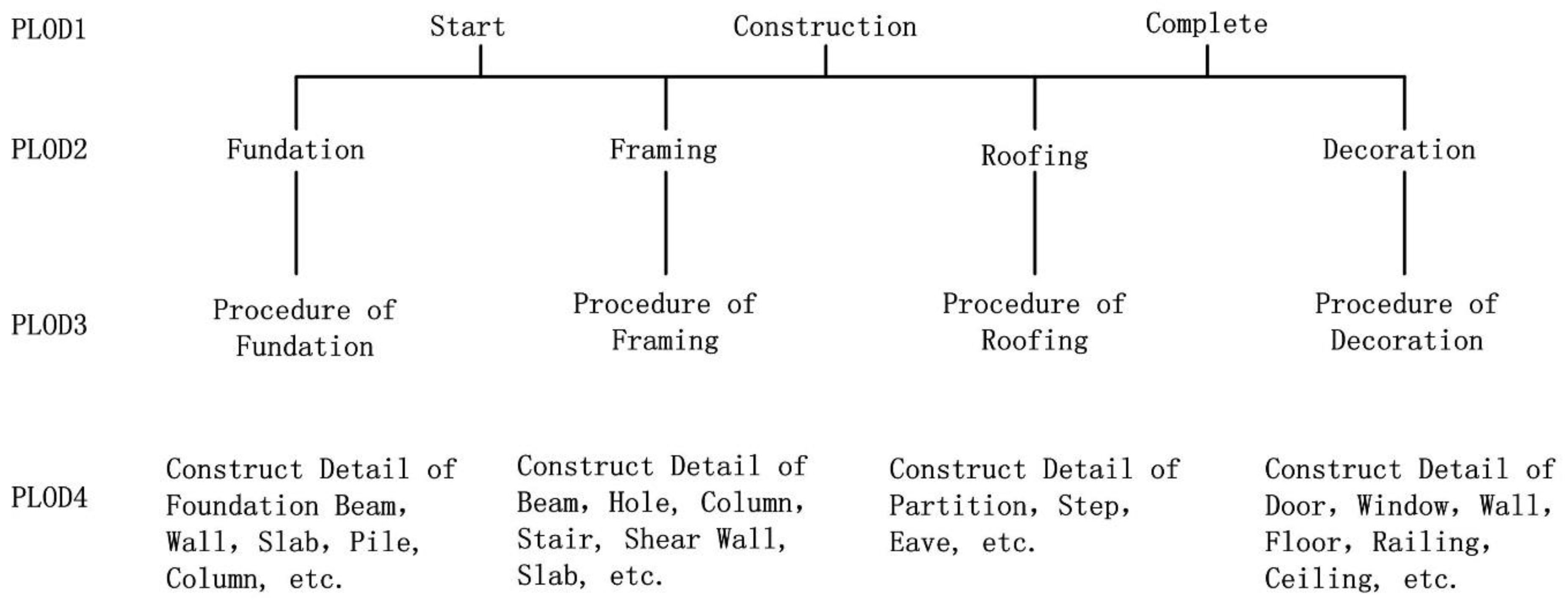
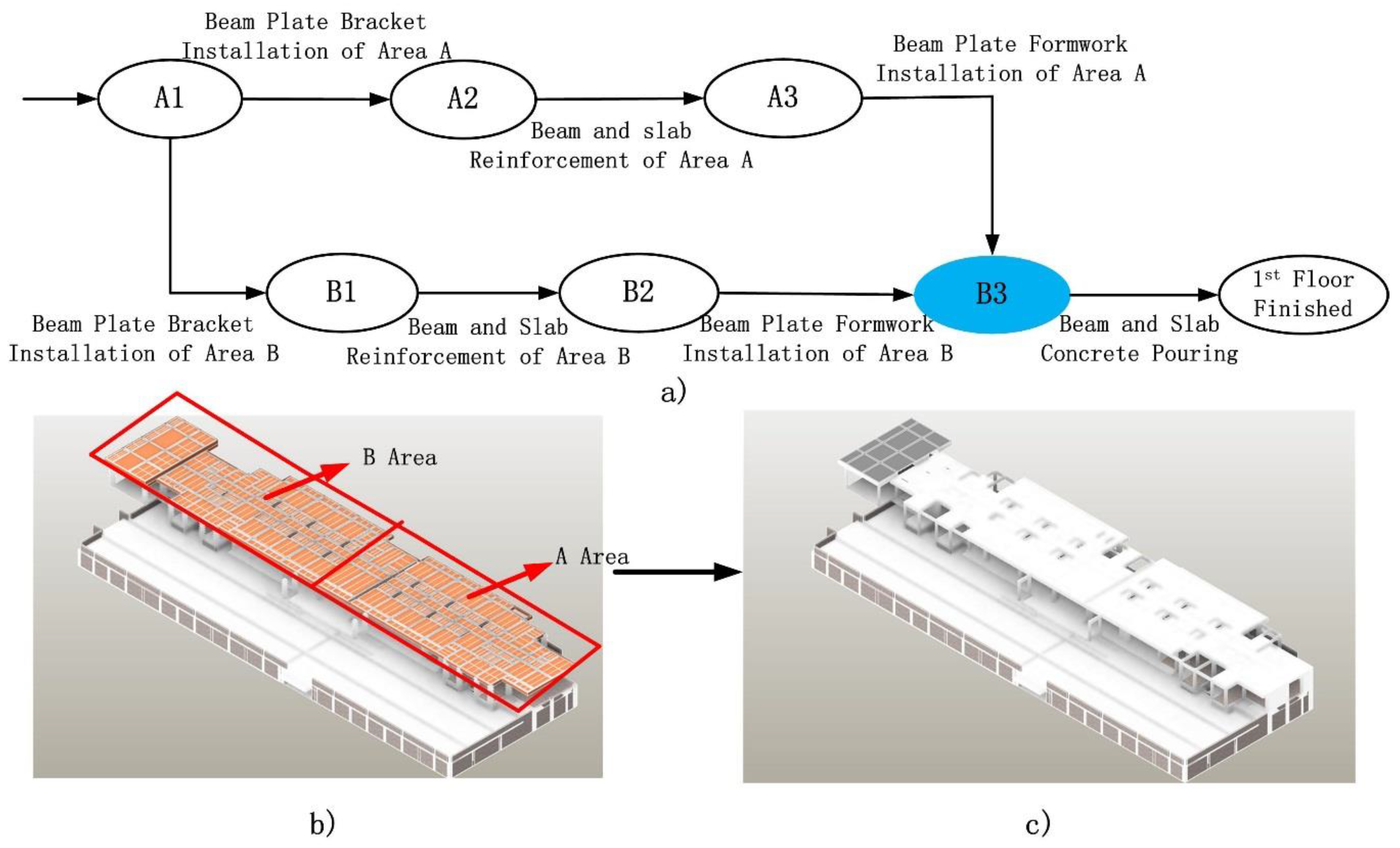
4.2.2. Creation of the PLOD Model

The original IFC model of the research data involves only the construction process corresponding to the PLOD4 level. After establishing the IFC to BCPADE mapping relationship, the models of the PLOD1 to PLOD3 levels are not created and should be derived based on the PLOD4 model. To construct the PLOD1 to PLOD3 models from the PLOD4 model, two issues must be solved, which are first, the creation of the evolution layer of the PLOD1 to PLOD3 models and second, the creation of the object layer of the PLOD1 to PLOD3 models.
a) Creation of the PLOD model of evolution layer
Each level of PLOD is nested, which means the activity of the upper level corresponds directly to the process of the lower level (Figure 7). Therefore, deriving the coarse-grained activity of the upper level from the fine-grained process of the lower level essentially implies merging the lower-level process composed of multiple activities into a single activity of the upper level. In accordance with the above definitions of the various levels of PLOD, we used the method shown in Figure 21 to merge the activities of the lower-level process into the upper-level activity.
As shown in Figure 21, the activity of the upper level can be derived from the activities of the process on the lower level. For example, in the PLOD4 level, the construction process of a certain story comprises activities such as beam plate bracket installation, beam and slab reinforcement, beam plate formwork installation, and beam and slab concrete pouring. These activities of the process are merged into the activity of PLOD3: Construction of 1st Story (Figure 21). The construction of the other PLOD models can also be implemented similarly, step-by-step.
b) Creation of the PLOD model of the object layer
The above method creates relationships between activities at different levels. On this basis, the objects associated with the activities of PLOD1–PLOD3 levels must be derived step-by-step. As the resolution of objects in different PLODs is distinct, it is necessary to simplify the objects of each PLOD to meet the requirement. The steps are as follows:
(i) Data preprocessing for PLOD4
The IFC model used in this study corresponds to the PLOD4 level of BCPADE, and the grain size is refined to the construction details of the relevant building elements. For example, the production process of the cast-in-place reinforced concrete beam and floor slab described in Figure 22 has undergone activities such as beam plate bracket installation, beam and slab reinforcement, beam plate formwork installation, and beam and slab concrete pouring. After completing these activities, the beams and slabs inside the building are poured. Therefore, in this process, both removal of the object (the formwork is removed after pouring) and merging of the object (the concrete is poured into steel bars to form reinforced concrete beams, column, etc.) occurred. However, the existing object association mechanism of IFC cannot express such removal and merging of objects. Therefore, the data need to be preprocessed, and these changes need to be edited manually into the PLOD4 level of BCPADE. Subsequently, the four collections of newly constructed, removed, merged, and changed objects of each activity in PLOD4 can be created manually.
(ii) Derivation of the amount of change of objects in activities at a higher level
In BCPADE, the activities at a higher level correspond directly to its sub-process, which contains the activities at the lower level. The amount of change of the building objects produced by the higher-level activity is equivalent to the total amount of change of the building objects of its associated sub-process. Therefore, the amount of object change corresponding to each activity in the model can be derived from the bottom-up (Figure 23).
(iii) Simplification of the building objects
After obtaining the amount of object change associated with each activity, the model still cannot meet the hierarchical representation requirements of PLOD. As the building objects associated with each level are derived as objects at level PLOD4, it becomes necessary to simplify the PLOD1–PLOD3 building objects according to their level in Table 1. Mature methods already exist to simplify the LOD of objects, as this problem has been investigated by several researchers. We employed the method described in [37] to simplify the objects in PLOD1–PLOD3 to generate lower-resolution objects from PLOD4.

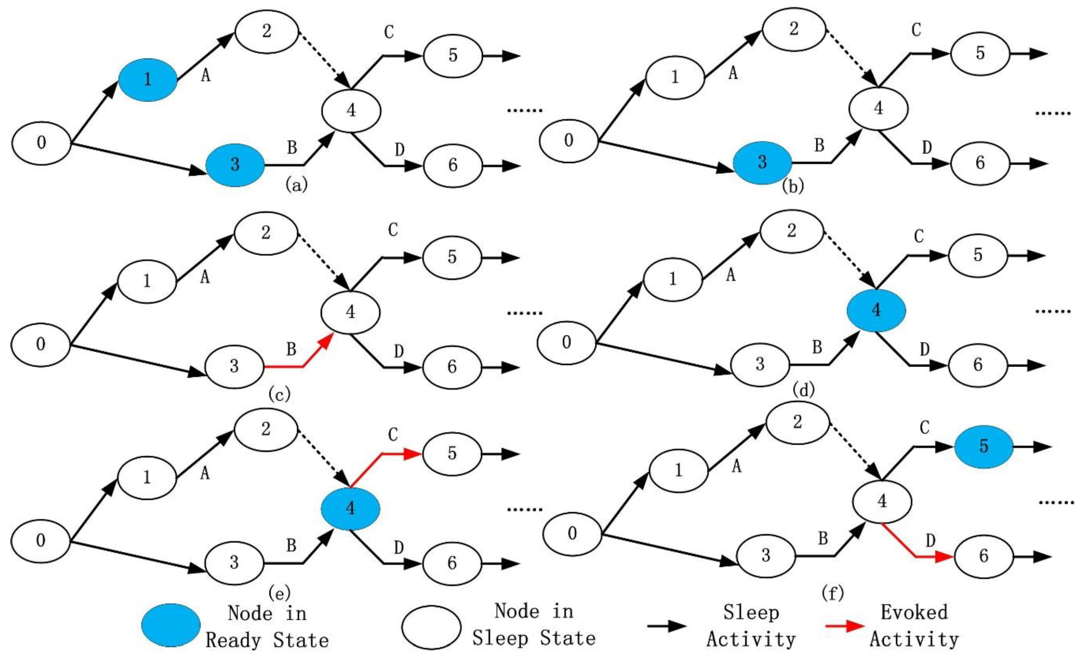
4.2.3. Driving Mechanism of BCPADE

Based on the created model, corresponding driving factors were added to automate the flow of the model. Three alternative driving methods were considered: manual interactive driving, driving based on the scheduled time of the construction process, and driving based on the actual start time of the construction process. As the third method can reflect the real situation of the construction process, it was used to drive the model. At the start time of an activity, an event that causes the activity is triggered, and the specific activity is performed. The detailed steps are as follows:
  • Initialize the event list according to the actual starting time (realStartTime attribute) of each activity, set all the finishState of the activities to zero, and set the readyState of the starting node to zero (and the readyState of other nodes to one).
  • Listen to the events. When an event triggers, go to the next step.
  • Look for the associated activity A by attribute relActivity of the event and the associated pre-node N by its attribute preNode. If node N is not in the ready state, the activity will not start, and the next step is performed. Otherwise, go to Step 5.
  • Create a new event in the event list, of which the scheduled time is 1 h later than the origin. Then, go to Step 2.
  • For node N, find the subsequent activities based on the attribute subActivities and ascertain whether they are all running or finished according to the attribute finishState. If they are finished, set N to the sleep state.
  • Start the activity and change its finishState to one. When the activity ends, change its finishState to two and proceed with the next step.
  • Find the subsequent node of the activity. For found node M, find all pre-order activities according to the attribute preActivities to ascertain whether they are all finished. If they are finished, set M to the ready state and go to the next step. Otherwise, go to Step 2.
  • Ascertain whether there are subsequent virtual activities associated with M. If so, launch the virtual activities directly. If not, set M to the sleep state. For each virtual activity, proceed with Step 7.
  • Return to Step 2.
The process flow is automated in this way, based on the actual times of the construction process. The visualization of the building construction process model is presented in Figure 24, which shows the flow of the building construction process according to the stage. The foundation construction stage mainly represents the construction process of the objects underground. The framing construction stage represents the construction process of each story of the building. The roof stage obviously represents the construction process of the roof and the decoration stage of the decoration process of the relevant building elements. The activity of each stage is associated with the start and end times of the stage, and a number of regular cycles are repeated in a certain area. The construction activity of the stage is completed at the end time. In each stage, the professional division of labor is clear, i.e., each type of worker cooperates and alternates depending on the relationship between different types of work. Therefore, the stage and correlative characteristics of the construction process are represented well throughout the simulation.

4.3. Discussion

4.3.1. Comparison with IFC

Although a construction process model represented by IFC is available in BIM, the BCPADE is more suitable for the simulation of the building construction process at city level, mainly with respect to the following aspects:
a) Multi-scale Expression
Compared with the single building level, the simulation of the construction process at the city level relates to a larger amount of data. Therefore, the process model is required to support expressions at multiple spatiotemporal scales. The PLOD model defined by BCPADE adequately represents the hierarchical structure of the construction process and can well express the different levels of detail of the building evolution process at multiple spatiotemporal scales. In addition, it corresponds to the LOD model originally defined by CityGML. As shown in Figure 25, at the PLOD1 level, the object has the coarsest granularity and the smallest amount of data, which is suitable for a wide range of evolution process simulations. The model can be refined into the four major stages of PLOD2, namely, foundation, framing, roofing, and decoration, which is suitable for a smaller range of evolution process simulations. In addition, this level of PLOD2 can be refined further to a finer-grained level. With such capability, the hierarchical characteristics of BCPADE are represented well and it can perform efficient simulations at multiple spatiotemporal scales at city level.
b) Efficient logical structure
In comparison with IFC, CityGML is designed to represent various objects in 3D cities. However, information on resources required in the construction process (Figure 26), such as labor and funds, is not considered by the model. As BCPADE eliminates redundant information for 3D cities, it has a more concise logical structure to support the construction process model. Therefore, BCPADE enables adopting a simpler and more efficient manner to represent the building construction process at the city level.
c) Appropriate Object Association Mode
There are significant differences between BCPADE and IFC related to their way of associating processes with building objects. In IFC, activities and objects are associated with the relationship “IfcRelAssignsToProcess” (Figure 27). However, this way of association can only show that these building objects participate in the process, but cannot express clearly the evolutionary behavior of the objects in the process such as adding, removal, merging, change, and the like. This leads to the user of the model having to rely on own experience to determine the evolutionary behavior of the relevant building object, which can give rise to errors. In contrast, BCPADE clearly defines the behaviors of building objects in the process, which means that the model can express the evolution of objects such as adding, removal, merging, and change. As shown in Figure 27, after the concrete is poured, the original steel and concrete are merged into building members such as beams, columns, and floors, and the formwork is removed from the scene. BCPADE accurately expresses this evolutionary behavior and generates evolutionary results, as shown in Figure 27b and 24c. Therefore, the object-association model allows BCPADE to simulate the evolution of the building objects accurately.
d) Strong constraints of activities in the construction process
Additionally, BCPADE differs from IFC with regard to process control because of the inclusion of state information in the construction process model to constrain the flow of the process. When the previous activities are not completed, the subsequent activities do not have the starting condition and cannot be in the ready state. In such an instance, even if an event triggering the subsequent activities occurred, they could not be started. With this mechanism, the previous and subsequent activities of the process are strongly constrained and the flow of the process can be more realistic.
As shown in Figure 27, most projects involve several construction teams working synchronously. A floor may have different construction areas and each construction area is worked in accordance with the order of bracket, reinforcement, and formwork. After a certain construction team is done, it needs to wait for other construction teams to finish their corresponding tasks to avoid cracks forming. The model incorporates this constraint between pre-order work and subsequent work very well. Only when all the working groups are finished does the B3 node transit to the ready state, and the subsequent activity “Beam and slab concrete pouring” can then start.

4.3.2. Comparison with Other Work Related to the Integration of IFC with CityGML

Since the emergence of CityGML 2.0, researchers have gradually realized the importance of interaction between BIM and GIS and conducted several studies based on this topic [17,18,38,39]. The motivation behind these studies was to achieve the mutual mapping of building objects in the core models of the two domains (IFC and CityGML), including the mapping of building elements such as doors and windows, mapping of building spaces such as rooms, and mapping of utility networks. This study is a further extension of the aforementioned studies. In addition to the mapping of building objects, the mapping of process objects from IFC to BCPADE is also implemented. When compared with other work related to the integration of IFC with CityGML, the main issues found in this study are the mapping of process information and construction of the PLOD model. This study enables the city objects in CityGML to be truly dynamic, rather than just being the initial or background data. It lays the foundation for the conversion of process information from BIM to GIS.

4.3.3. Relationship with the Emerging CityGML3.0

CityGML 3.0 is about to emerge in the near future. The studies conducted by several researchers that were based on CityGML 2.0 will be integrated into the newer version of CityGML. The study of this article may be linked to CityGML3.0 in the following two ways.
a) Unified expression of the construction process of man-made objects
CityGML 3.0 will be complemented by a new construction module that defines concepts common to all types of man-made constructions like buildings, bridges, tunnels, and other constructions [40]. This modification of the module fundamentally distinguishes between the man-made and natural objects involved in CityGML. Buildings are the most typical man-made objects in 3D cities. Fundamentally speaking, its evolutionary process has the characteristics of stage, hierarchy, and correlative that are also the characteristics of other man-made objects in the construction process. Therefore, the results of this study can be further expanded, and subsequently, the construction process of man-made objects in CityGML3 can be uniformly expressed.
b) Making city objects truly dynamic
The dynamizer [30] and versioning modules [31] can be incorporated into the CityGML3.0 as new features. However, as mentioned earlier, these modules are unable to describe characteristics such as stage, hierarchy, and correlative that existed during the evolution of buildings. Unlike the abovementioned modules, BCPADE models the construction process and can make the city objects be truly dynamic. Overall, the focus of BCPADE is different from that of the other two modules mentioned above. In the future, BCPADE can be used in conjunction with the dynamizer and versioning modules to truly express the dynamic phenomena of cities in 3D.

4.3.4. Limitations

a) The main purpose of CityGML is to model the CityObjects as well as related analyzes and simulations in 3D cities (such as indoor positioning, crowds evacuation, building evolution simulation, etc.). Therefore, the research in this paper is applicable to 3D cities. Its purpose is not to replace the current software in the AEC field for construction management, but to support the modeling and simulation of building information in 3D cities.
b) Construction process data produced in the AEC field can be converted to BCPADE to provide a rich data source for a 3D city. Therefore, BCPADE can also serve as a bridge to facilitate data interoperability between GIS and BIM. But at present, automatic conversion is not possible and it requires some manual intervention. This is mainly reflected in two steps:
i) Data preprocessing for PLOD4.
This stage cannot be automated because the IFC model cannot describe the evolutionary behaviors of building objects in activities, but only uses the relationship "IfcRelAssignsToProcess" to associate objects that participate in the process. Therefore, it needs to create evolutionary behaviors based on experience and knowledge, which requires a significant amount of manual intervention. Therefore, for BIM information to be automatically converted into BCPADE, a mechanism to describe the object behaviors needs to be introduced into the model. For example, the "IfcRelAssignsToProcess" relationship could be expanded to include attributes that express object behaviors. With this mechanism to describe object behaviors, it is possible for IFC to automatically be converted to BCPADE.
ii) Creation of the PLOD model of evolution layer
During the creation of the evolution layer of the PLOD model, it is necessary to merge lower-level activities with higher-level activities. A certain amount of semantic information is required to support this process, e.g., the description of the activities. However, this is not mandatory (the attribute of LongDescription in IfcTask is optional and lacks a fixed standard). This makes it impossible to merge lower-level activities with higher-level activities in a unified mode, and manual intervention is required. Therefore, for BIM information to be automatically converted into BCPADE, it is necessary to constrain the process objects, such as IfcTask, to obtain the corresponding semantic information for automatic conversion.
c) The utility network is an important component of the building. Therefore, de Laat et al. [17] and Hijazi et al. [18] studied the modeling of the UtilityNetworkADE and its interoperation with the IFC model, respectively. However, this study mainly focuses on the civil engineering stage of the buildings and does not consider the evolutionary process of the building infrastructure. Theoretically, the infrastructures inside the building constitute a relatively independent system that is different from the main structure of the building. However, the construction process of building infrastructures and that of the main structure of the building have certain commonalities. First, the construction activities of building infrastructures also consider characteristics such as the stage, hierarchy, and correlative; second, in the construction activities, evolutionary behaviors such as adding, removal, merging, and change of the objects still exist. Therefore, the rationale of this study could be expanded to further study the evolutionary process of building infrastructures.

5. Conclusions and Recommendations

We analyzed the main characteristics of the building construction process, established a logical model, and extended it into the BCPADE. Taking BIM data as an example, our model is able to realize semi-manual conversion to BCPADE and the subsequent simulation of the building construction process.
Our conclusions are as follows.
  • BCPADE can simulate the building construction process at multiple spatiotemporal scales at the city level and is compatible with the original LOD model of CityGML.
  • The logical structure of BCPADE reduces redundant information such as labor and cost, making the model more concise and efficient.
  • The object association mode of BCPADE is able to accurately express the evolutionary behaviors of adding, removal, merging, and change of building objects, thereby achieving accurate simulation of the building construction process.
Future research will focus on several topics:
(1)
The upcoming CityGML 3.0 will be complemented by a new construction module defining concepts that are common to all types of construction such as buildings, bridges, and tunnels [40]. We will expand our model to include the construction processes of these objects to further improve the support of CityGML for dynamic processes.
(2)
We will realize the automatic conversion of IFC to BCPADE based on the mapping relationship between them.
(3)
There will be revisions to the CityGML Core module in the upcoming CityGML3.0. Therefore, BCPADE will need to be updated in accordance with the features of this new version.

Author Contributions

Formal Analysis, Chi Zhang, Chen Lin; Writing and Original Draft Preparation, Chi Zhang; Analysis, Liangchen Zhou; Methodology, Yunping Liu; Validation, Bingxian Lin; Funding Acquisition, Mingliang Che.

Funding

This study was supported by the National Natural Science Foundation of China (grant number 41501422), the National Natural Science Foundation of China (grant number 41571381), and the Nantong Key Laboratory Project (grant number CP12016005).

Conflicts of Interest

The authors declare no conflict of interest.

References

  1. OGC. OpenGIS® City Geography Markup Language (CityGML) Encoding Standard (Version 2.0). 2012. Available online: http://www.opengeospatial.org/standards/citygml (accessed on 4 April 2012).
  2. van den Brink, L.; Stoter, J.; Zlatanova, S. Establishing a national standard for 3D topographic data compliant to CityGML. Int. J. Geogr. Inf. Sci. 2013, 27, 92–113. [Google Scholar] [CrossRef]
  3. van den Brink, L.; Stoter, J.; Zlatanova, S. UML-based approach to developing a CityGML application domain extension. Trans. GIS 2013, 17, 920–942. [Google Scholar] [CrossRef]
  4. Stoter, J.E.; Ledoux, H.; van den Brink, L.; Klooster, R.; Janssen, P.; Beetz, J.; Penninga, F.; Vosselman, G. Establishing and implementing a national 3D standard in the Netherlands. Photogramm. Fernerkund. Geoinf. 2013, 2013, 381–392. [Google Scholar] [CrossRef]
  5. Li, L.; Luo, F.; Zhu, H.; Ying, S.; Zhao, Z. A two-level topological model for 3D features in CityGML. Comput. Environ. Urban. Syst. 2016, 59, 11–24. [Google Scholar] [CrossRef]
  6. Kaden, R.; Kolbe, T.H. Augmenting 3D city model components by geodata joins to facilitate ad-hoc geometric-topologically sound integration. ISPRS Ann. Photogramm. Remote Sens. Spat. Inf. Sci. 2012, 1, 215–220. [Google Scholar] [CrossRef] [Green Version]
  7. Boeters, R.; Ohori, K.A.; Biljecki, F.; Zlatanova, S. Automatically enhancing CityGML LOD2 models with a corresponding indoor geometry. Int. J. Geogr. Inf. Sci. 2015, 29, 2248–2268. [Google Scholar] [CrossRef] [Green Version]
  8. Çağdaş, V. An application domain extension to CityGML for immovable property taxation: A Turkish case study. Int. J. Appl. Earth. Obs. Geoinf. 2013, 21, 545–555. [Google Scholar] [CrossRef]
  9. Li, L.; Wu, J.; Zhu, H.; Duan, X.; Luo, F. 3D modeling of the ownership structure of condominium units. Comput. Environ. Urban. Syst. 2016, 59, 50–63. [Google Scholar] [CrossRef]
  10. Becker, T.; Nagel, C.; Kolbe, T.H. Integrated 3D modeling of multi-utility networks and their interdependencies for critical infrastructure analysis. In Advances in 3D Geo-Information Sciences; Springer: Berlin/Heidelberg, Germany, 2011; pp. 1–20. [Google Scholar]
  11. Becker, T.; Nagel, C.; Kolbe, T.H. Semantic 3D modeling of multi-utility networks in cities for analysis and 3D visualization. In Progress and New Trends in 3D Geoinformation Sciences; Springer: Berlin/Heidelberg, Germany, 2013; pp. 41–62. [Google Scholar]
  12. Kutzner, T.; Kolbe, T.H. Extending semantic 3D city models by supply and disposal networks for analysing the urban supply situation. In Proceedings of the Lösungen für eine Welt im Wandel, Dreiländertagung der SGPF, DGPF und OVG, 36; Wissenschaftlich-Technische Jahrestagung der DGPF, Bern, Switzerland, 7–9 June 2016; pp. 382–394. [Google Scholar]
  13. Kutzner, T.; Hijazi, I.; Kolbe, T.H. Semantic modelling of 3D multi-utility networks for urban analyses and simulations: The CityGML utility network ADE. Int. J. 3-D Inf. Model. 2018, 7, 1–34. [Google Scholar] [CrossRef] [Green Version]
  14. Kim, Y.J.; Kang, H.Y.; Lee, J. Development of indoor spatial data model using CityGML ADE. Int. Arch. Photogramm. Remote Sens. Spat. Inf. Sci. 2013, 1, 41–45. [Google Scholar] [CrossRef] [Green Version]
  15. Kim, Y.; Kang, H.; Lee, J. Developing CityGML indoor ADE to manage indoor facilities. In Innovations in 3D Geo-information Sciences; Springer: Cham, Switzerland, 2014; pp. 243–265. [Google Scholar]
  16. Dutta, A.; Saran, S.; Kumar, A.S. Development of CityGML application domain extension for indoor routing and positioning. J. Indian Soc. Remote Sens. 2017, 45, 993–1004. [Google Scholar] [CrossRef]
  17. de Laat, R.; van Berlo, L. Integration of BIM and GIS: The development of the CityGML GeoBIM extension. In Advances in 3D Geo-information Sciences; Springer: Berlin/Heidelberg, Germany, 2011; pp. 211–225. [Google Scholar]
  18. Hijazi, I.; Ehlers, M.; Zlatanova, S.; Becker, T.; van Berlo, L. Initial investigations for modeling interior utilities within 3D geo context: Transforming IFC-interior utility to CityGML/UtilityNetworkADE. In Advances in 3D Geo-Information Sciences; Springer: Berlin/Heidelberg, Germany, 2011; pp. 95–113. [Google Scholar]
  19. Mohd, Z.H.; Ujang, U.; Choon, T.L. Heritage house maintenance using 3D city model application domain extension approach. Int. Arch. Photogramm. Remote Sens. Spat. Inf. Sci. 2017, XLII-4/W6, 73–76. [Google Scholar] [CrossRef] [Green Version]
  20. Moshrefzadeh, M.; Donaubauer, A.; Kolbe, T.H. A CityGML-based façade information model for computer aided facility management. In Proceedings of the Bridging Scales-Skalenübergreifende Nah-und Fernerkundungsmethoden, 35. Wissenschaftlich-Technische Jahrestagung der DGPF, Cologne, Germany, 16–18 March 2015; pp. 133–143. [Google Scholar]
  21. Czerwinski, A.; Sandmann, S.; Stöcker-Meier, E.; Pluemer, L. Sustainable SDI for EU noise mapping in NRW—Best practice for INSPIRE. Int. J. Spat. Data Infrastruct. Res. 2007, 2, 90–111. [Google Scholar]
  22. Kumar, K.; Ledoux, H.; Commandeur, T.J.F.; Stoter, J.E. Modelling urban noise in CityGML ADE: Case of the Netherlands. ISPRS Ann. Photogramm. Remote Sens. Spat. Inf. Sci. 2017, IV-4/W5, 73. [Google Scholar] [CrossRef] [Green Version]
  23. Agugiaro, G.; Benner, J.; Cipriano, P.; Nouvel, R. The energy application domain extension for CityGML: Enhancing interoperability for urban energy simulations. Open. Geospat. Data Softw. Stand. 2018, 3, 2. [Google Scholar] [CrossRef]
  24. Nouvel, R.; Kaden, R.; Bahu, J.-M.; Kaempf, J.; Cipriano, P.; Lauster, M.; Benner, J.; Munoz, E.; Tournaire, O.; Casper, E.; et al. Genesis of the CityGML energy ADE. In Proceedings of the International Conference CISBAT 2015, Lausanne, France, 9–11 September 2015; LESO-PB: Lausanne, France, 2015; pp. 931–936. [Google Scholar]
  25. Benner, J.; Geiger, A.; Häfele, K.H. Virtual 3D city model support for energy demand simulations on city level–The CityGML energy extension. In Proceedings of the 21st International Conference on Urban Planning, Regional Development and Information Society, Hamburg, Germany, 22–24 June 2016; CORP: The Hague, The Netherlands, 2016; pp. 777–786. [Google Scholar]
  26. Coccolo, S.; Mauree, D.; Kämpf, J.H. Urban energy simulation based on a new data model paradigm: The CityGML application domain extension energy. A case study in the EPFL campus of Lausanne. Proceedings of 14th International Conference of the International Building Performance Simulation Association, Hyderabad, India, 7–9 December 2015; IBPSA: Toronto, Canada, 2015. [Google Scholar]
  27. Wate, P.; Saran, S. Implementation of CityGML energy application domain extension (ADE) for integration of urban solar potential indicators using object-oriented modelling approach. Geocarto Int. 2015, 30, 1144–1162. [Google Scholar] [CrossRef]
  28. Schulte, C.; Coors, V. Development of a CityGML ADE for dynamic 3D flood information. In Proceedings of the Joint ISCRAM-China and GI4DM Conference, Harbin, China, 4–6 August 2008. [Google Scholar]
  29. Prandi, F.; De Amicis, R.; Piffer, S.; Soave, M.; Cadzow, S.; Gonzalez Boix, E.; D’Hont, E. Using CityGML to deploy smart-city services for urban ecosystems. Int. Arch. Photogramm. Remote Sens. Spat. Inf. Sci. 2013, XL-4/W1, 87–92. [Google Scholar] [CrossRef] [Green Version]
  30. Chaturvedi, K.; Kolbe, T.H. Integrating dynamic data and sensors with semantic 3D city models in the context of smart cities. ISPRS Ann. Photogramm. Remote Sens. Spat. Inf. Sci. 2016, 4, 31–38. [Google Scholar] [CrossRef] [Green Version]
  31. Chaturvedi, K.; Smyth, C.S.; Gesquière, G. Managing versions and history within semantic 3D city models for the next generation of CityGML. In Advances in 3D Geoinformation; Springer: Berlin/Heidelberg, Germany, 2017; pp. 191–206. [Google Scholar]
  32. Kam, C.; Fischer, M.; Hänninen, R. The product model and Fourth Dimension project. J. Inf. Technol. Constr. (ITcon) 2003, 8, 137–166. [Google Scholar]
  33. Zhang, J.P.; Cao, M.; Zhang, Y.A. 4D construction management system based on IFC standard and engineering information model. Eng. Mech. 2005, 22 (Suppl.), 220–227. [Google Scholar]
  34. Moder, J.J.; Phillips, C.R. Project Management with CPM and PERT; Van Nostrand Reinhold: New York, NY, USA, 1970. [Google Scholar]
  35. Gröger, G.; Plümer, L. CityGML–Interoperable semantic 3D city models. Photogramm. Remote Sens. 2012, 71, 12–33. [Google Scholar]
  36. Wei, Z.L.; Wang, C.M.; Wang, L.J.; Xie, F.P. Building Construction Technology. Master’s Thesis, Tsinghua University Press, Beijing, China, 2017. [Google Scholar]
  37. Zhang, C. Research on Interior-Exterior Holistic Building Data Model. Ph.D. Thesis, Nanjing Normal University, Nanjing, China, 2014. [Google Scholar]
  38. Nagel, C.; Stadler, A.; Kolbe, T.H. Conceptual requirements for the automatic reconstruction of building information models from uninterpreted 3D models. In Proceedings of the Academic Track of the Geoweb 2009-3D Cityscapes Conference, Vancouver, BC, Canada, 27–31 July 2009. [Google Scholar]
  39. El-Mekawy, M.; Östman, A.; Shahzad, K. Towards interoperating CityGML and IFC building models: A unified model based approach. In Advances in 3D Geo-Information Sciences; Springer: Berlin/Heidelberg, Germany, 2011; pp. 73–93. [Google Scholar]
  40. Utzner, T.; Kolbe, T.H. CityGML 3.0: Sneak preview. In Proceedings of the PFGK18-Photogrammetrie-Fernerkundung-Geoinformatik-Kartographie, 37. Jahrestagung in München, Munich, Germany, 6–9 April 2018; pp. 835–839. [Google Scholar]
Figure 1. Basic characteristics of the building construction process: (a) stage and hierarchical characteristics of the construction process; (b) correlative characteristics of the construction process.
Ijgi 08 00576 g001
Figure 2. Research framework.
Ijgi 08 00576 g002
Figure 3. Example of an arrow diagramming method (ADM).
Ijgi 08 00576 g003
Figure 4. Support of the ADM for the stage characteristics of the construction process.
Ijgi 08 00576 g004
Figure 5. Staged construction workflow.
Ijgi 08 00576 g005
Figure 6. Process levels of detail (PLOD) hierarchy.
Ijgi 08 00576 g006
Figure 7. Extension for hierarchical characteristics.
Ijgi 08 00576 g007
Figure 8. Relationship between the process and building objects: (a) construction process model, and (b) CityGML building model.
Ijgi 08 00576 g008
Figure 9. Correlation between the process and objects.
Ijgi 08 00576 g009
Figure 10. Relationships between process, nodes, activities, and events.
Ijgi 08 00576 g010
Figure 11. Conversion between the ready and sleep states of a node.
Ijgi 08 00576 g011
Figure 12. Reverse limit on the node state with activity.
Ijgi 08 00576 g012
Figure 13. Process flow.
Ijgi 08 00576 g013
Figure 14. BCPADE in CityGML.
Ijgi 08 00576 g014
Figure 15. The youth teachers’ apartment building of Nantong University and the description of its data.
Ijgi 08 00576 g015
Figure 16. Steps to generating BCPADE from the IFC data.
Ijgi 08 00576 g016
Figure 17. The process model in IFC.
Ijgi 08 00576 g017
Figure 18. Relationship between the process objects of BCPADE and IFC.
Ijgi 08 00576 g018
Figure 19. Creating of the arrow diagram.
Ijgi 08 00576 g019
Figure 20. Relationship between the process objects of BCPADE and IFC.
Ijgi 08 00576 g020
Figure 21. Merging from the activities of the lower level process to the higher-level activity.
Ijgi 08 00576 g021
Figure 22. Sample construction process of building elements at PLOD4 level.
Ijgi 08 00576 g022
Figure 23. Relationship of the amount of change of the building objects in different PLODs.
Ijgi 08 00576 g023
Figure 24. Overall construction process: (a) process model, (b) foundation, (c) framing, (d) roofing, (e) decoration, and (f) completion.
Ijgi 08 00576 g024
Figure 25. Multi-scale expression of the model.
Ijgi 08 00576 g025
Figure 26. How the activity (IfcTask) in IFC is associated with other objects.
Ijgi 08 00576 g026
Figure 27. Evolutionary behavior of the objects in activities: (a) stages of the workflow, (b) time before concrete is poured (node B3 is ready), and (c) time after concrete is poured (formwork removal).
Ijgi 08 00576 g027
Table 1. Correspondence between the construction process PLOD and CityGML LOD.
PLOD LevelCorresponding LOD LevelCorresponding Building Objects
PLOD1LOD2building, outer walls, roof, ground
PLOD2LOD3building elements on façade, such as windows, doors
PLOD3LOD4building elements in the inner of building, such as beams, stairs
PLOD4Extended LOD4building elements in the inner of building as well as the auxiliary objects related in the manufacture of the building elements

