1. Introduction
In recent years, micro- and low-cost satellite development has increased in the private sector, including small- and medium-sized companies, venture companies, and universities [
1]. In particular, nanosatellites of 100 kg or less have been developed by private-sector groups because of their lower cost and development time compared to conventional satellites. Nanosatellites can be more readily applied to space-based research and industry, and can serve as a platform for demonstrating newly developped techonology [
2,
3].
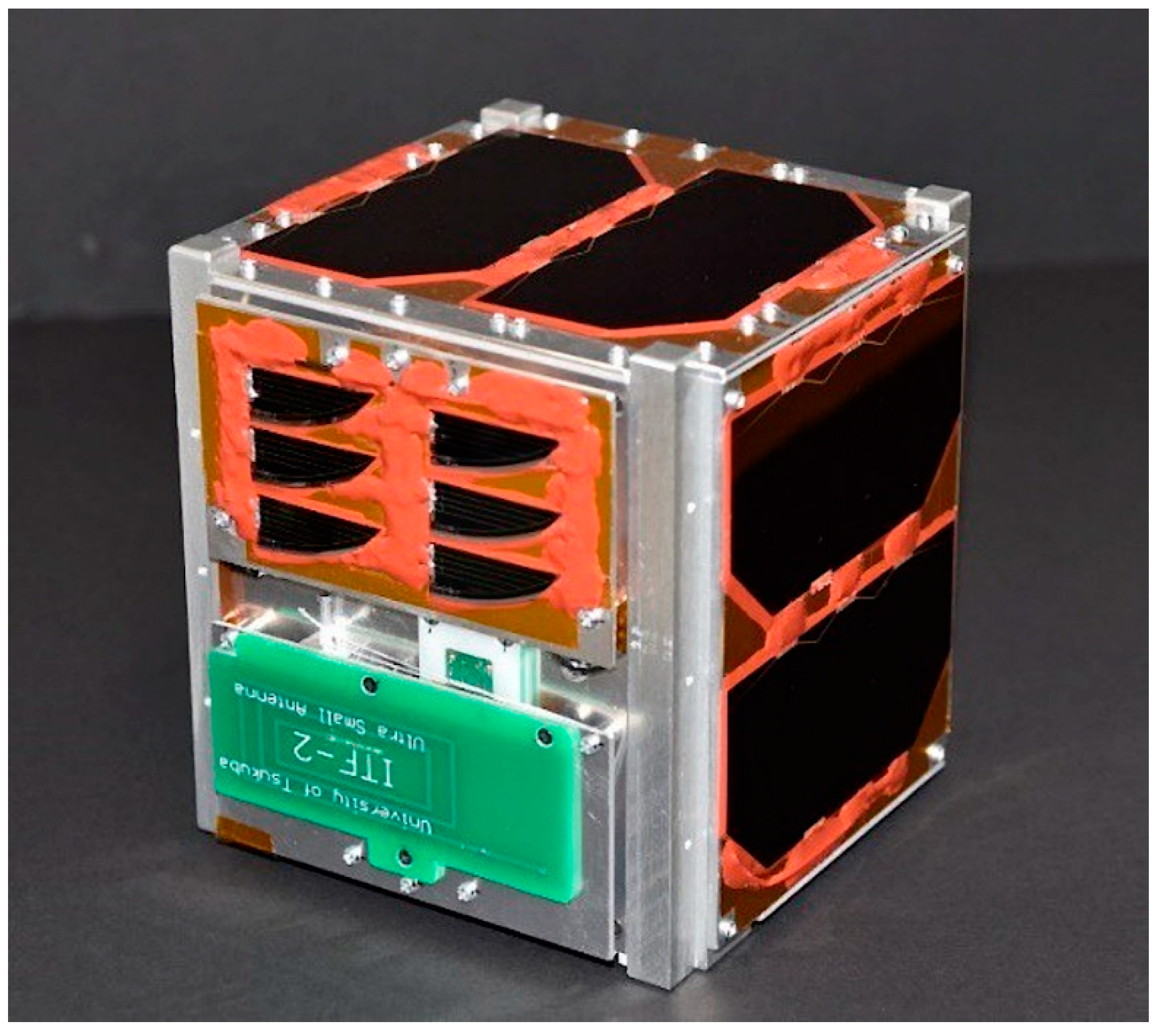
Figure 1 shows the CubeSat nanosatellite, which weighs several kilograms and can be developed within a short period at a low cost. Thus, CubeSat can potentially facilitate new space development by functioning as a platform for the rapid demonstration of new technologies in space and for space business. CubeSat can also be the subject of university-level space education and research [
4].
Research and development of highly reliable space components and materials that can withstand long periods for uasge in extreme space environments has been conducted throughout the history of satellite development [
5]. In accordance with current technological developments, the use of electronic components (i.e., digital cameras, microprocessors, communication transceivers, and DC/DC converters) designed for consumer applications, such as laptop computers, smartphones, and automobiles, is now expected [
6]. This is because consumer electronic components do not require space environment tests, such as severe radiation tests, and newer technologies can be rapidly implemented in such products; therefore, they are smaller and have a higher performance, lower power consumption, and lower cost than space components, which are developed for use in space environments. Although consumer components are not developed for use in space environments, sufficient reliability may be ensured by thorough reliability evaluation tests involving simulated space environments, such as vibration, thermal vacuum, and radiation tolerance evaluation tests.
In Japan, nanosatellite-class communication systems have not changed significantly over the past decade [
7]. At present, only one company produces communication devices for space applications that combine consumer integrated circuits (ICs) with discrete components for the 144 and 430 MHz amateur frequency bands used by many universities [
8]. This communication equipment is highly reliable and has been used by several universities in Japan; however, currently, Japanese research on communication equipment and antennas is lagging behind the experimental and pioneering work being conducted in other countries [
9,
10]. Although detailed experimental research on Doppler shift tolerance in the 434 MHz band using the CubeSat LoRa module has been reported [
11], few studies have evaluated the radiation tolerance of consumer electronic components for potential use in CubeSat; such evaluations are important to determine component feasibility for space application.
The objective of this study is to demonstrate the process of applying consumer products to satellite space missions after subjecting them to appropriate space environmental testing. This approach can reduce the time and cost if the required component for the space research mission is not available in the market. In our mission, as a suitable communication system in terms of the cost and design flexibility was unavailable, we developed and verified a communication system for a CubeSat-class nanosatellite that actively utilizes current consumer communication devices. We fabricated a small software-controllable communication system using a current consumer communication IC and single-chip microcomputer. The prototype was then evaluated through radiation testing. In previous studies, we conducted radiation tolerance evaluation on microcomputers using heavy-ion irradiation [
12,
13]. In this study, we evaluate the radiation tolerance of the transceiver IC using the same method. In detail, the radiation tolerances of the consumer communication IC and single-chip microcomputer are evaluated, and the possibility of applying the small communication module in space is examined, assuming installation in a nanosatellite, considering the measures for stable operation. We also evaluate the Doppler shift tolerance to confirm the module sensitivity when the frequency is shifted by the high-speed movement of the satellite. Finally, we design and develop a communication substrate that can be mounted on a CubeSat using devices with high-space-utilization potential; this design is demonstrated in orbit using a low-Earth-orbit (LEO) satellite.
The remainder of this paper is organized as follows.
Section 2 describes the wireless communication system developed in this work and the testing methodology.
Section 3 presents and analyzes the test results and discusses the feasibility for satellite application.
Section 4 discusses the performance of the proposed communication component based on a real-space demonstration using CubeSat. Finally,
Section 5 summarizes the conclusions of this study and discusses future work.
2. Materials and Methods
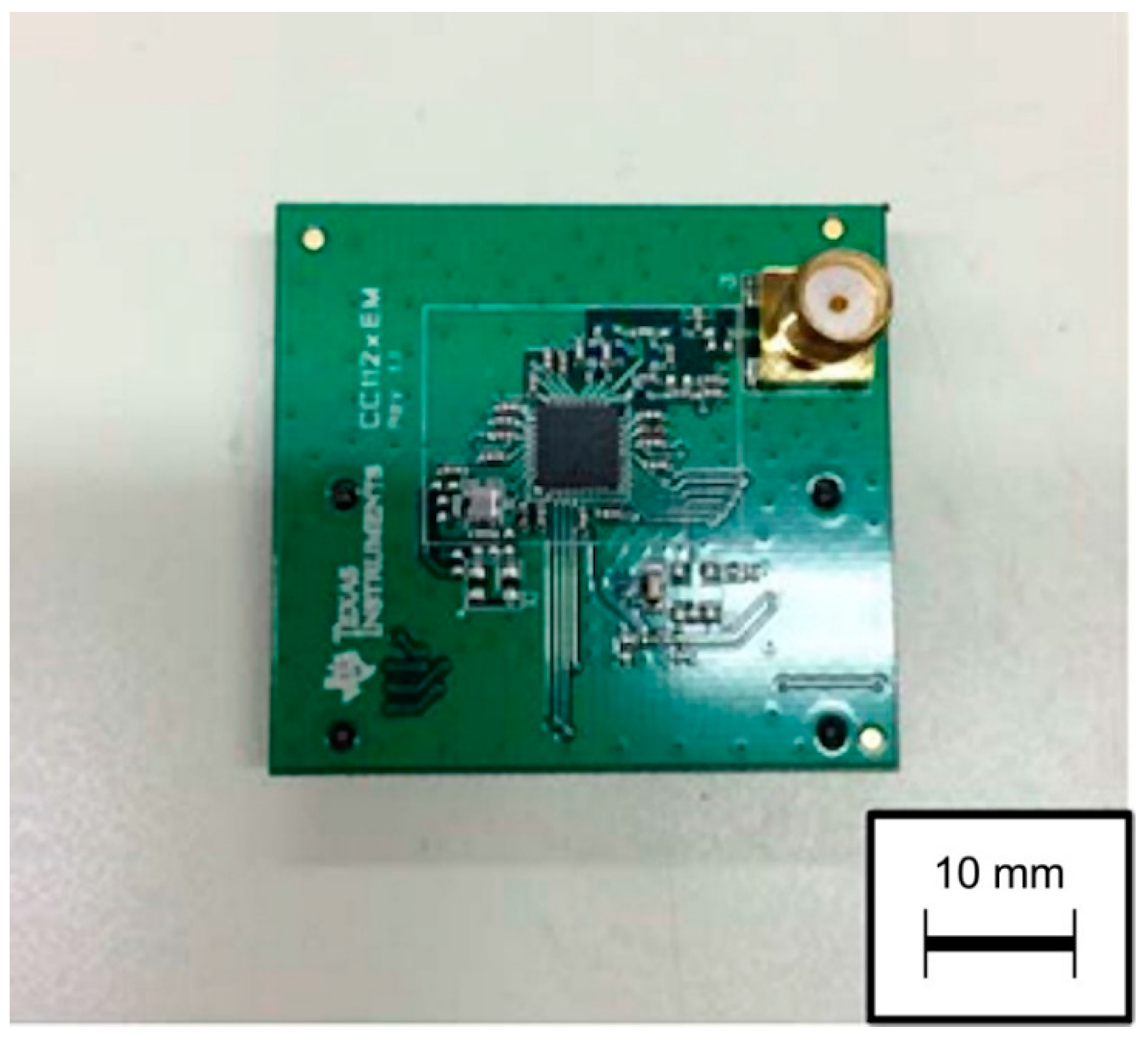
The wireless communication system developed in this work consists of a small single-chip wireless communication module and control microcomputer; i.e., the control IC. For the former, we used a module that is commercially available as a consumer electronic component: CC1120 (Texas Instruments).
Figure 2 and
Table 1 show the appearance and specifications of the wireless communication module, respectively. This low-cost and sub-1 GHz wireless communication module can be utilized in the industrial, scientifc and medical (ISM), space reseach, and hamradio bands, and is designed for low-power wireless tranceiver applications. In addition, because it is an all-in-one software-controlled IC, miniaturization is achieved by condensing the transmission and reception functions onto a single chip; this setup is in contrast to conventional space wireless devices in which the transmitter and receiver occupy two separate substrate sections [
8]. In addition, because the transmission output, data rate, modulation method, and other values are software-adjustable, no hardware modification is required, and the system functions can respond flexibly to a given objective. A similar attempt was made in the Greek CubeSat project [
14].
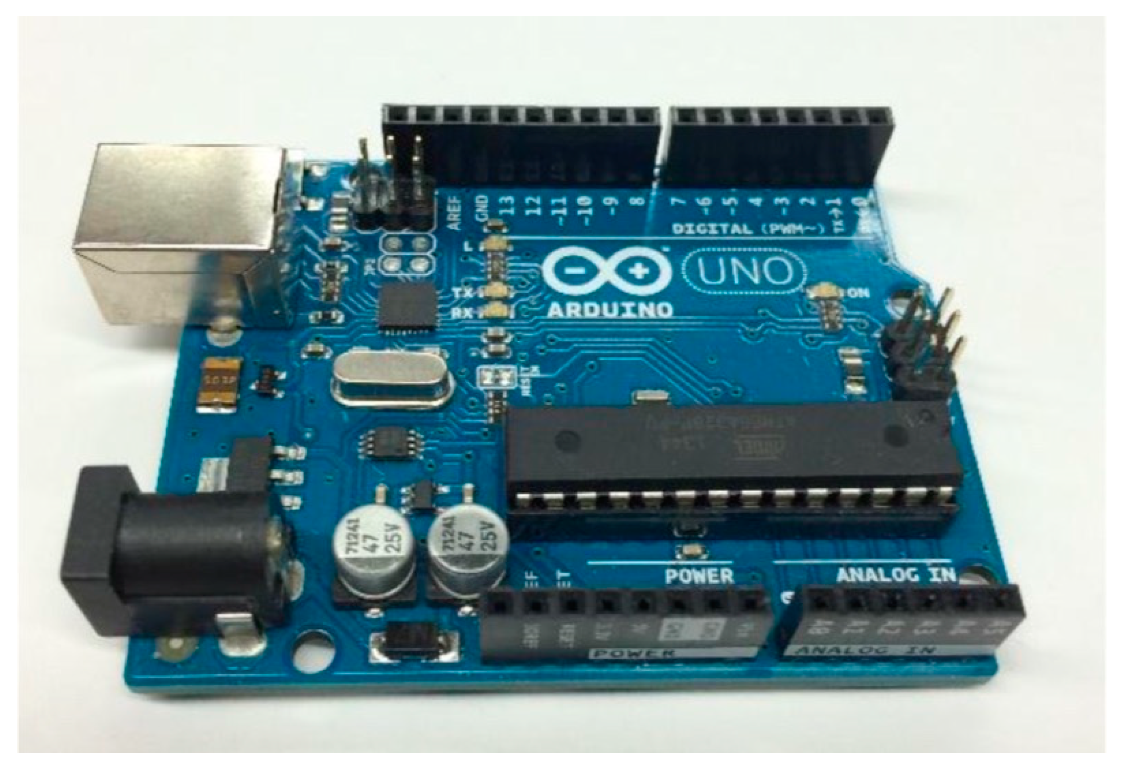
An Arduino UNO R3 (ARDUINO) microcomputer (
Figure 3) was used as the control IC of the small single-chip wireless communication module.
Table 2 lists the main specifications. The Arduino UNO R3 is open-source. Moreover, this microcomputer is based on the ATmega328P (Microchip Technology) microcontroller, which has many A/D I/O lines and an A/D converter, rendering it highly versatile. Abundant information on the Arduino integrated development environment is available online [
15]. Importantly, as the Arduino UNO R3 can be used as a development environment, an experimental environment can be easily constructed.
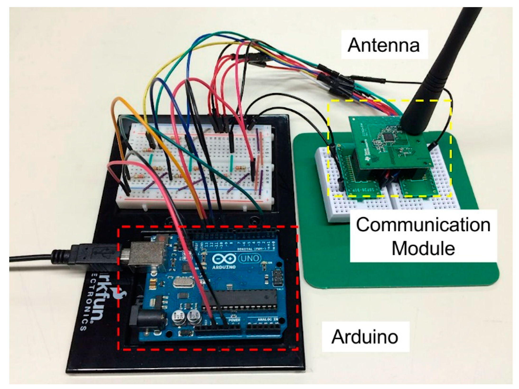
We fabricated a wireless communication system using the small single-chip wireless communication module and Arduino microcomputer described in the previous section.
Figure 4 shows a photograph of the fabricated wireless communication system. The Arduino microcomputer was used as the control IC to switch the transmission and reception modes of the wireless communication module and to set parameters, such as the frequency, modulation method, communication speed, and transmission power. We prepared two such communication systems, and verified that the transmission and reception between them was effective. We then conducted various space environment tests using one of these systems as a testbed.
The effects of radiation on semiconductor devices can be roughly classified into total ionizing dozing effects and single-event effects (SEEs). In the former, the effects of charged particles accumulate in the semiconductor and change its characteristics over time; in the latter, the charged particle effects temporarily cause a single-event upset (SEU) in the memory or a single-event latch-up (SEL) in the switching device [
16]. Because SEEs are a stochastic phenomenon, the SEE occurrence moment during an experiment cannot be predicted. Therefore, we conducted radiation testing under constant monitoring to investigate the effect of the radiation environment on the operation of the wireless communication system, and thus, evaluate its performance. Although constant monitoring is necessary for radiation tests on semiconductors, manual resets and reboots may damage the semiconductor [
17,
18]; therefore, we applied an improved automated monitoring method developed in previous studies [
19,
20].
When a wireless communication system is applied to a satellite component as a small communication module, the radiation tolerances of the control IC and wireless module are important. Even if the radiation tolerance of the latter is high, its overall reliability will decrease if the radiation tolerance of the former is extremely low. Therefore, the radiation tolerance evaluation of both components is necessary, and a control-IC microcomputer with equivalent or higher radiation tolerance than that of the wireless module should be selected. Various radiation tolerance evaluations have been reported to date concerning consumer microcomputers for installation in small satellite applications, including the PIC16F877 [
12], ATmega128 [
12], MSP430FR5739 [
13], and H8-3048 [
21] devices. Although the Greek team has also used a software configurable transceiver IC at almost the same time, the radiation tolerance results have not been reported. In this study, radiation tolerance evaluations were performed for both the CC1120 wireless module and the ATmega2560 microcontroller, which has an Arduino development environment and many control pins, and is highly versatile when mounted on a satellite.
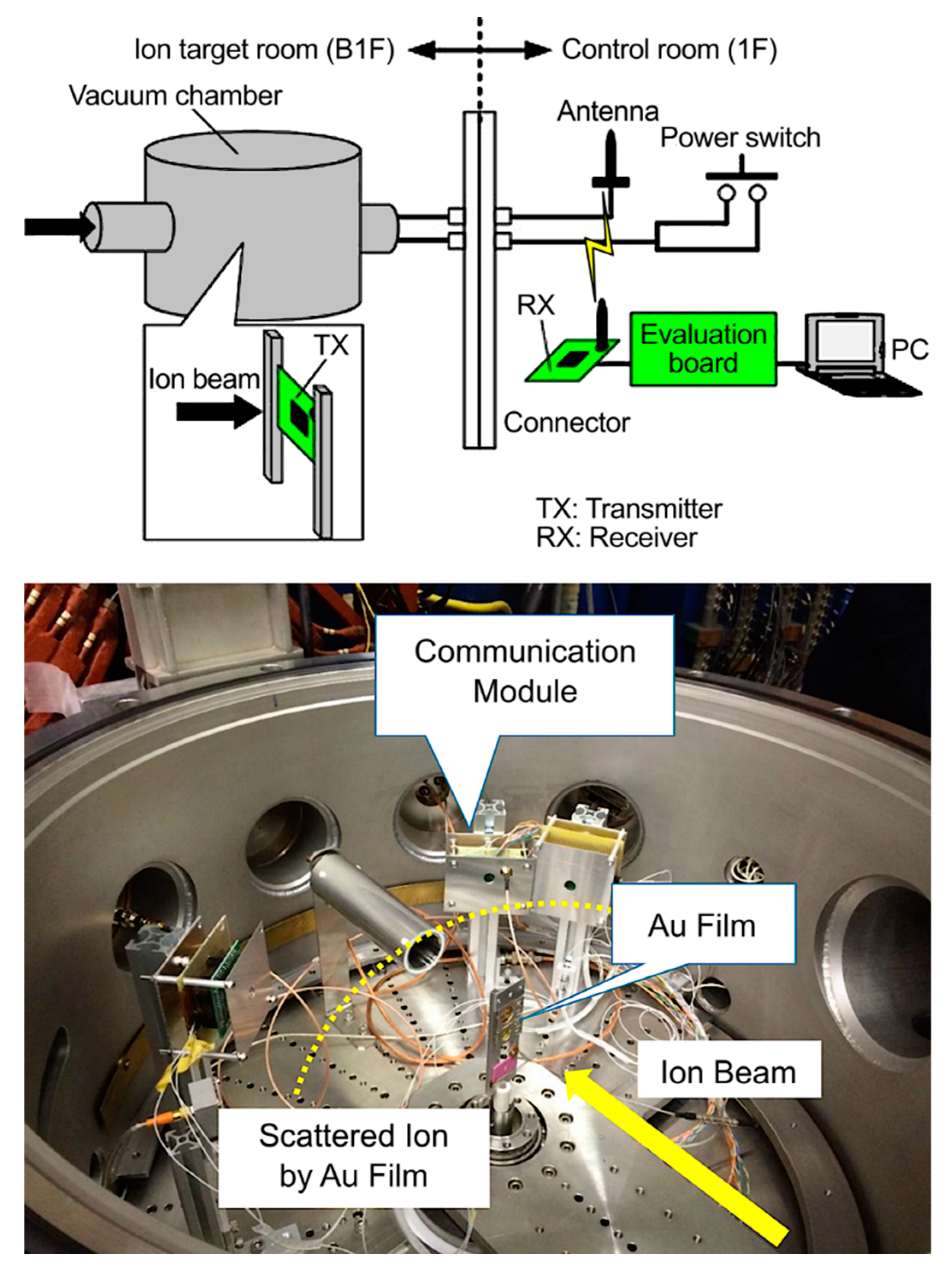
In this study, we conducted irradiation tests at the Tandem Accelerator Facility (Tokai Village, Naka District, Ibaraki Prefecture) of the Japan Atomic Energy Agency (JAEA). In the irradiation tests, an Au thin-film was used as the scattering film for the ion-beam irradiation part. Each test object was placed on the circumference for irradiation (Rutherford scattering) to enable the simultaneous acquisition of the test data for the small single-chip wireless communication module and microcomputer, and improve the test efficiency.
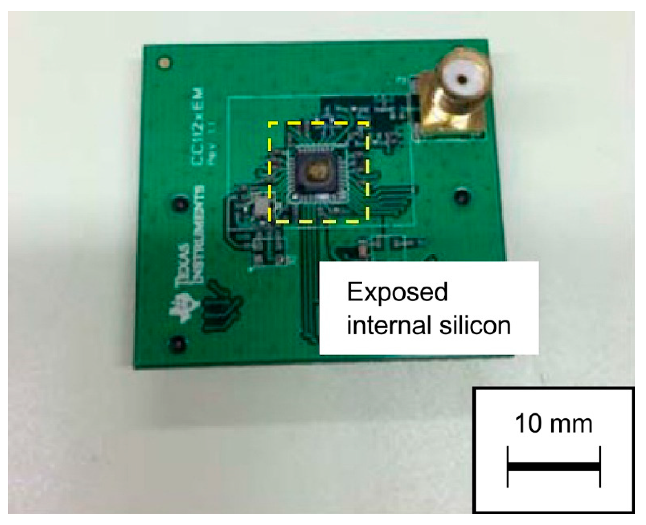
Figure 5 shows a photograph of the Au scattering film used in the irradiation test. During the test, the package on top of the IC was removed to expose the Si substrate inside the IC. Through this decapping process, which was used in prior studies [
20,
22], the effect of radiation attenuation by the IC package was eliminated (
Figure 6).
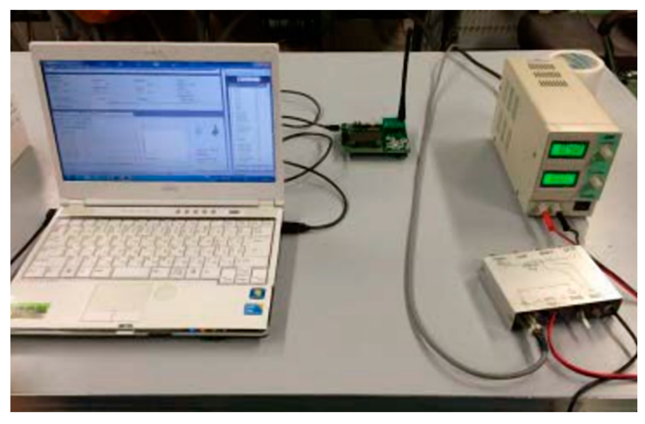
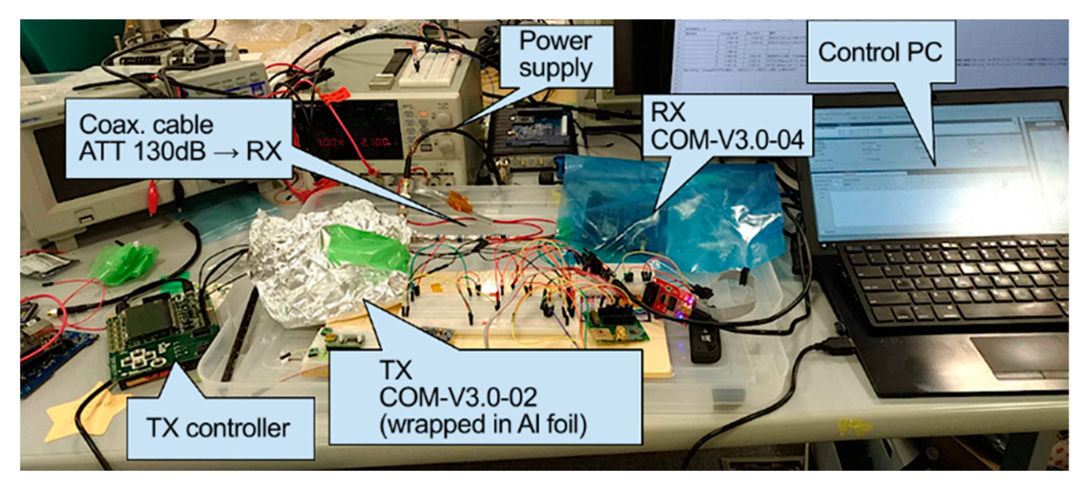
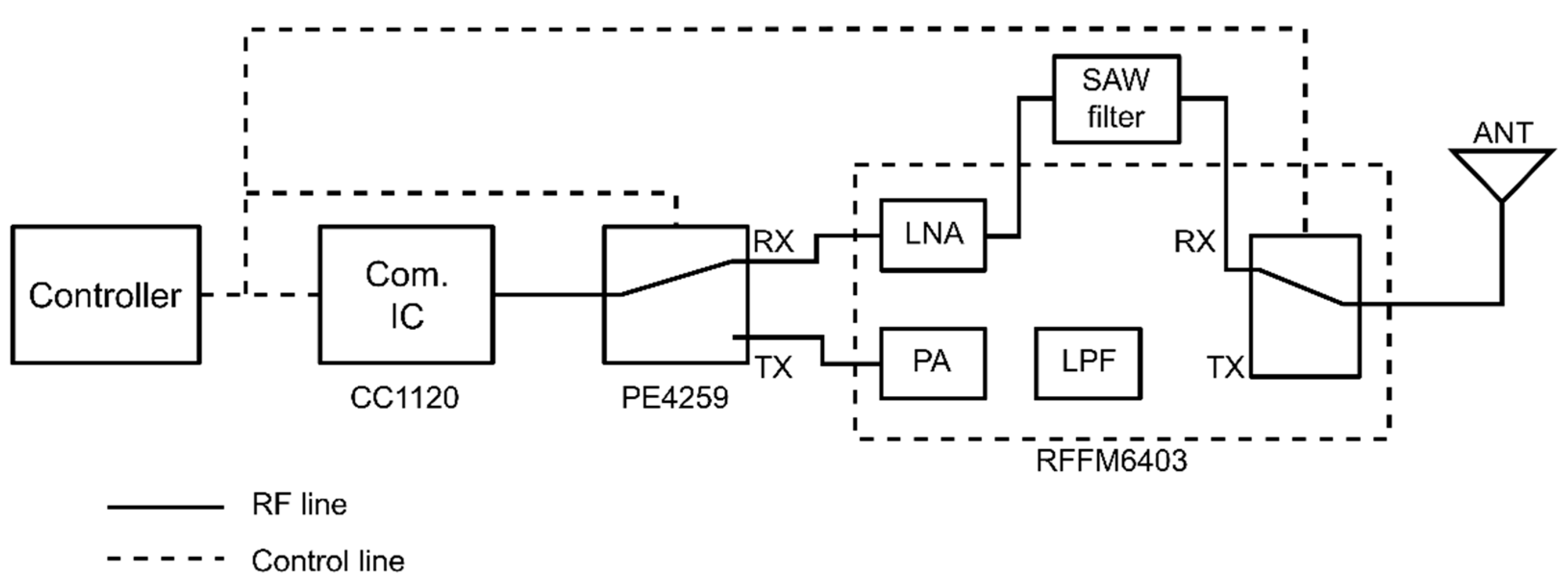
Figure 7 shows the schematic and photograph of the test setup. The wireless communication module installed within the chamber was set to transmit test data continuously in a constant transmission mode using the control Arduino installed outside the chamber. To confirm the communication operation, and determine the current and voltage variations during the irradiation test, a high-frequency cable and power cable were connected to an external power supply. An antenna and switch circuit were installed in the control room and implemented via a connector from inside the chamber. Equipment to receive the radio waves transmitted from the wireless module was installed in the control room, and the time history, transmission data, and received signal strength indicator (RSSI) at the time of reception were visually monitored and recorded at all times.
Figure 8 shows communications operation and transmission data monitoring during the irradiation test in the control room.
SEUs and SELs are the main effects of radiation exposure on semiconductor devices. Therefore, we obtained the tolerance data for these phenomena. Three types of ion beams (Ar, Kr, and Xe) were selected as the heavy-ion species for irradiation. Based on the irradiation tests performed by Chiba et al. [
12,
13], evaluations were first performed for Xe, which has the highest probability of producing a single event, followed by those for the lower-energy Kr and Ar. The SEUs and SELs of the wireless communication module were measured at the linear energy transfer (LET) value, i.e., the radiation energy transfer rate of each irradiated ion species. The SEU and SEL tolerances with respect to the LET were evaluated.
Table 3 lists the LET values of each ion species impacting the Si under the test conditions.
For SEU measurement during the test, the SEUs were detected by transmitting prespecified data from the wireless communication system on the transmission-mode side within the chamber and by monitoring the data received on the reception-mode side outside the chamber. Using the error detection function of the wireless communication module during data transmission and reception, we counted every error that occurred during irradiation as one SEU.
For the SEL measurement during the test, the SELs were detected by monitoring the difference in the current consumption and RSSI of the wireless communication module on the transmission-mode side. In space, when a phenomenon considered to be an SEL occurs, functionality is restored by reclosing the power supply. Therefore, in this study, when a phenomenon determined to be an SEL occurred, the power supply was reclosed following a careful check of the operation status.
3. Results
3.1. Irradiation Test Results
The transmission-mode side of the wireless communication module was placed within the irradiation chamber, and irradiation was conducted while performing wireless communication.
Table 4,
Table 5 and
Table 6 list the representative SEUs measured under Ar, Kr, and Xe irradiation, respectively. For each measurement, continuous observation was performed until an SEU occurred. Then, the IC was reset, and the next test sequence was initiated. During measurements 2 and 3 under Xe irradiation (
Table 6), many bit errors resulting from SEUs occurred almost simultaneously; the total number of bit errors is shown.
The upset cross-section was calculated using the following equation [
21]:
where
is the upset cross-section [cm
2/bit];
A is the number of SEUs [times];
T is the measurement time [s];
b is the number of target bits [bits]; and
f is the fluence rate [times/s/cm
2].
The wireless communication module has 256 bytes of RAM and several registers for external control and configuration, with various command formats. In this device, if the radiation changes a register value, the prescribed wireless communication becomes impossible. To account for this, b of the test object was calculated using Equation (1) as twice the installed memory capacity, considering the existence of the register. For the case of no SEU occurrence, the σ calculation assumes that an SEU occurs once, under the basis that the probability of an SEU occurring under operation in a space environment is never zero.
The irradiation test results confirmed that SEUs were generated in the wireless communication module by each ion beam. The SEU occurrence frequency was the highest under Xe irradiation, which had the highest LET value. In addition, for each ion beam, communication operation on the transmission-mode side stopped several times as a result of SEU-occurrence error detection. In such cases, wireless communication was facilitated once again by reclosing the power.
Under Kr and Xe irradiation, a phenomenon that may have been an SEL was observed. The current consumption, which was 110 mA during normal communication operations, approximately doubled to 260 mA; however, the wireless communication module continued to function as normal. When the power supply was reclosed, the current returned to the normal value, and normal wireless communication before and during irradiation was confirmed. Therefore, the wireless communication module test object was not permanently damaged by the short SEL-induced current increase.
3.2. Predictive Analysis of SEU Incidence in Space Environment
We conducted a predictive analysis of SEU incidence in a space environment based on the irradiation test results using Cosmic Ray Effects on Micro Electronics (CRÈME) [
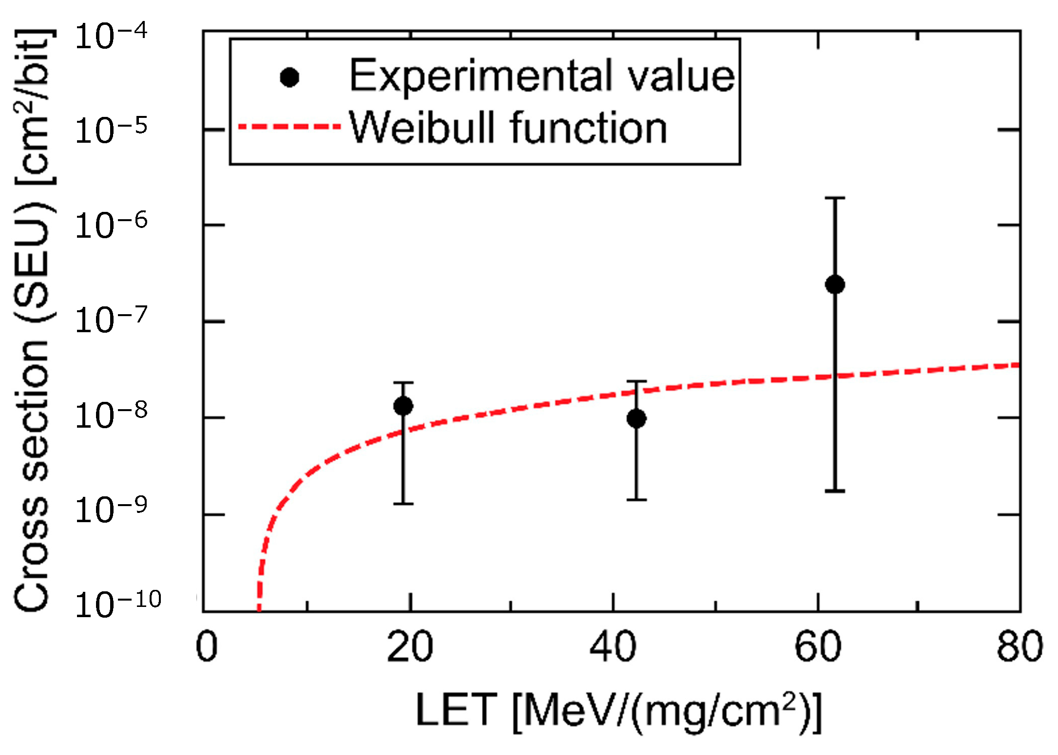
23], which is an analysis software package developed by the Naval Research Laboratory for predicting the error occurrence probability in a space environment. Specifically, the SEU incidence for an LEO with a 400 km altitude was calculated by inputting the test data into this software package. First, the Weibull-curve characteristic parameters were obtained to input to CRÈME by constructing LET–
graphs based on the test data. The equation used for the Weibull curve was as follows [
21]:
where
is the saturation upset cross-section [cm
2/bit];
L is the LET [MeV/(mg/cm
2)];
L0 is the threshold LET [MeV/(mg/cm
2)];
W is the scale parameter [MeV/(mg/cm
2)]; and
S is the shape parameter.
Figure 9 shows a graph of the LET—
characteristic curve fitted with Equation (2) and
Table 7 lists the SEU curve parameters calculated from
Figure 9.
Next, we evaluated parameters, such as σ
0 and
L0, listed in
Table 7, using CRÈME [
23]. As the input to CRÈME for the environmental conditions relating to space radiation, we used conditions 1–4 in
Table 8 for the solar activity and geomagnetic weather; the SEU incidence prediction results are given in the same table. Condition 1 corresponded to the strongest radiation in space environment; i.e., the least favorable condition. From
Table 8, the probability of SEU incidence in the wireless communication module was 2.64 × 10
−9 [SEU/bit/day] for Condition 1, according to CRÈME. The test result for the wireless communication module was 1.08 × 10
−5 [SEU/device/day], suggesting that SEU incidence for a single device was approximately once in 3000 months. From the above results, the module radiation tolerance is considered sufficient for practical use in space environment, if the SEU occurrence frequency is at approximately this level.
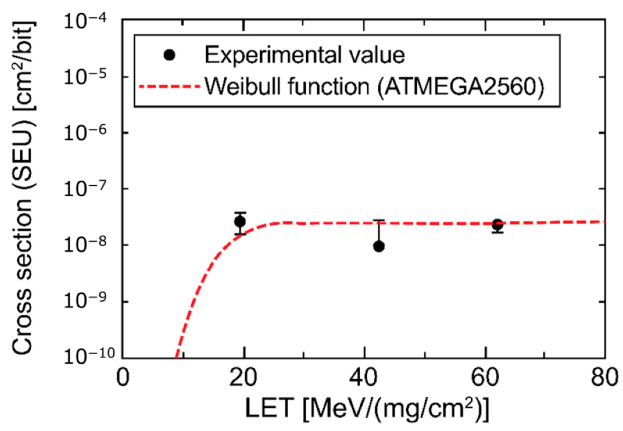
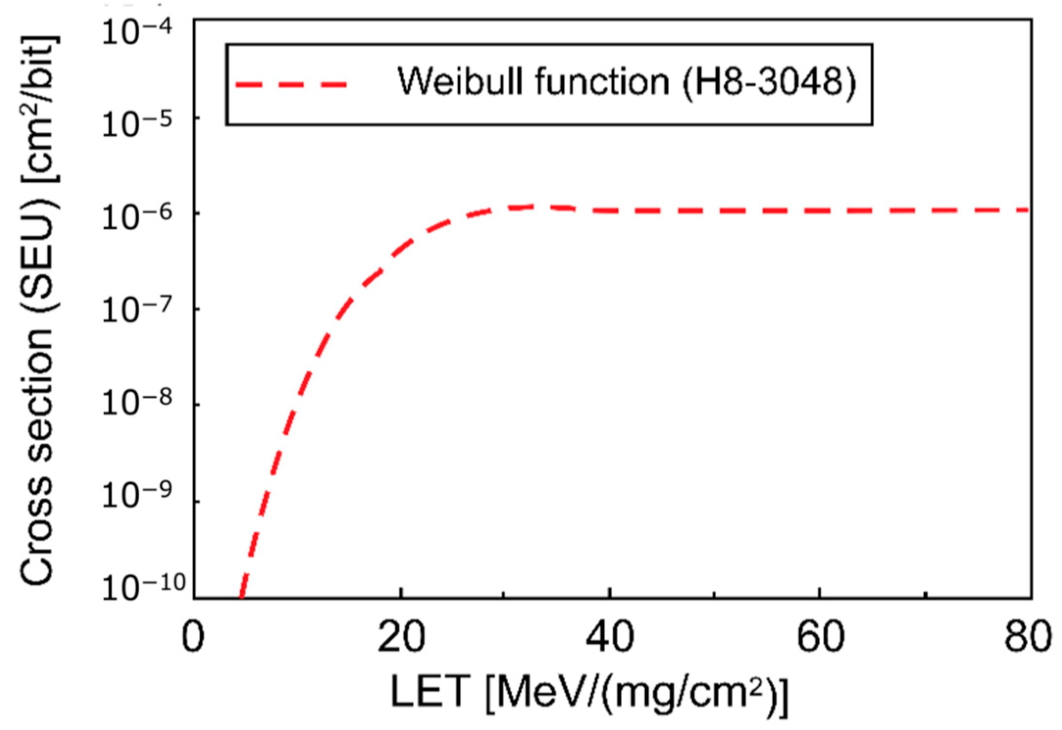
3.3. Comparison with the Microcomputer Radiation Tolerance
We compared the radiation tolerance of the wireless module with those of two microcomputers: an AVR microcontroller (ATmega2560, Microchip Technology Inc., Chandler, AZ, USA), which is increasingly being used owing to the popularity of Arduino, and a microcomputer with a proven track record in space (H8-3048) [
24].
For the ATmega2560, we used the results obtained simultaneously in this test, and for the H8-3048, we used the results previously obtained by Ishikawa et al. [
21].
Figure 10 and
Figure 11 show the SEU σ values corresponding to the ATmega2560 and H8-3048
L values, respectively.
The comparison of
Figure 9 and
Figure 10 reveals comparable SEU σ values for the wireless module and ATmega2560 at approximately 1.0 × 10
−8 [cm
2/bit]. However, the comparison of
Figure 9 and
Figure 11 reveals that the SEU σ values of H8-3048 were higher than those of the wireless module; thus, H8-3048 has a lower radiation tolerance than that of the wireless module.
Based on the above comparison, if the C1120 wireless module is to be applied to satellite components as a small communication system, a microcomputer with the same radiation tolerance level as the wireless module, such as ATmega2560, may be desirable to use as the control IC rather than a microcomputer with a lower radiation tolerance, such as H8-3048.
3.4. Doppler Shift Tolerance
When a communication device is mounted on a satellite, it must have a sufficient reception bandwidth with respect to the Doppler shift caused by high-speed movement to avoid reception performance degradation. Thus, a Doppler shift tolerance test was performed. As the experimental conditions of this test, the satellite was assumed to receive a signal at 400 km altitude; the receiving frequency at the satellite was fixed, and a signal with a slightly shifted frequency was sent.
Table 9 lists the Doppler shift test parameters, and
Figure 12 shows the apparatus.
The test results confirmed that reception was possible in the range of ±38 kHz from the center frequency (437.387–437.463 MHz). The frequency shift was determined using the following equation:
where
f is the received frequency;
f0 is the transmitted frequency;
c is the velocity of light;
v is the satellite velocity; and
β is the angle between the satellite velocity vector and Earth-based transmitter position vector relative to the satellite [
11]. From Equation (3), the frequency shift in the 430 MHz band for a satellite in LEO at 400 km altitude is approximately ±10 kHz, which confirms that communication is possible regardless of the relative velocity at the time of passage.
3.5. Other Environmental Tests
As previously mentioned, to use commercial products for space applications, sufficient reliability evaluation tests, such as vacuum, vibration, and thermal tests, need to be conducted, in addition to radiation tests. In this study, a vacuum test was performed during the radiation test because the interior of the radiation chamber is maintained in a high-vacuum state with a pressure in the order of 10−5 Pa. Because the CC1120 transceiver IC is a one-chip component, and its vibration tolerance can be expected to be notably higher than that of the printed circuit board (PCB), we combined its vibration test with that of the entire CubeSat; no defect was detected. For the thermal environment test, because the IC is surface mounted on the PCB, the generated heat is mostly dissipated by conduction, which is expected to be the same under the vacuum environment as that under atmospheric pressure. Furthermore, we performed the thermal vacuum test for the entire CubeSat system.
5. Conclusions
We designed and developed a wireless communication system incorporating a consumer communication IC for expected application to satellite components. The developed communication system was subjected to radiation tests to evaluate its radiation tolerance; the wireless module exhibited sufficient radiation tolerance to withstand the space environment. Using a microcomputer with the same or higher radiation tolerance than that of the wireless module as the module control IC, the complete module can attain sufficient radiation tolerance for application to satellite components.
The Doppler shift tolerance was investigated considering potential installation on a satellite; hence, it was confimed that an FSK signal was received at ±38 kHz center frequency in the 435 MHz band, and that unlimited communication could be established, even for an LEO satellite at 400 km altitude, where the Doppler shift effect is large.
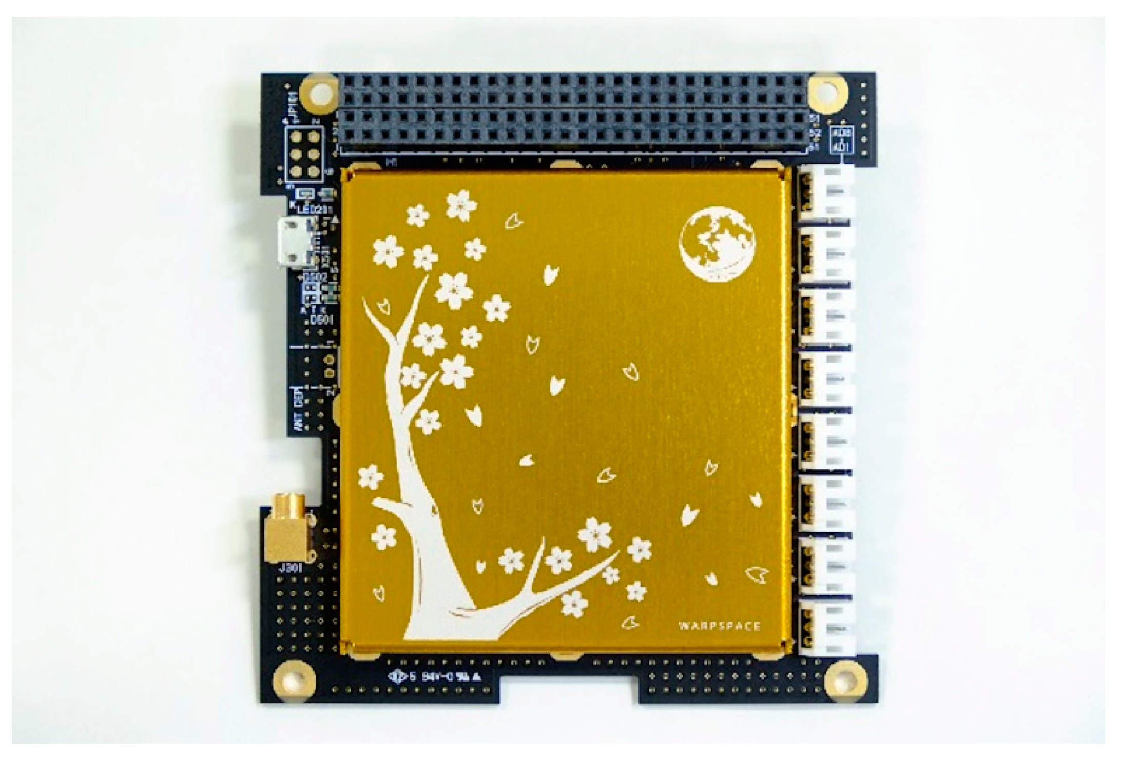
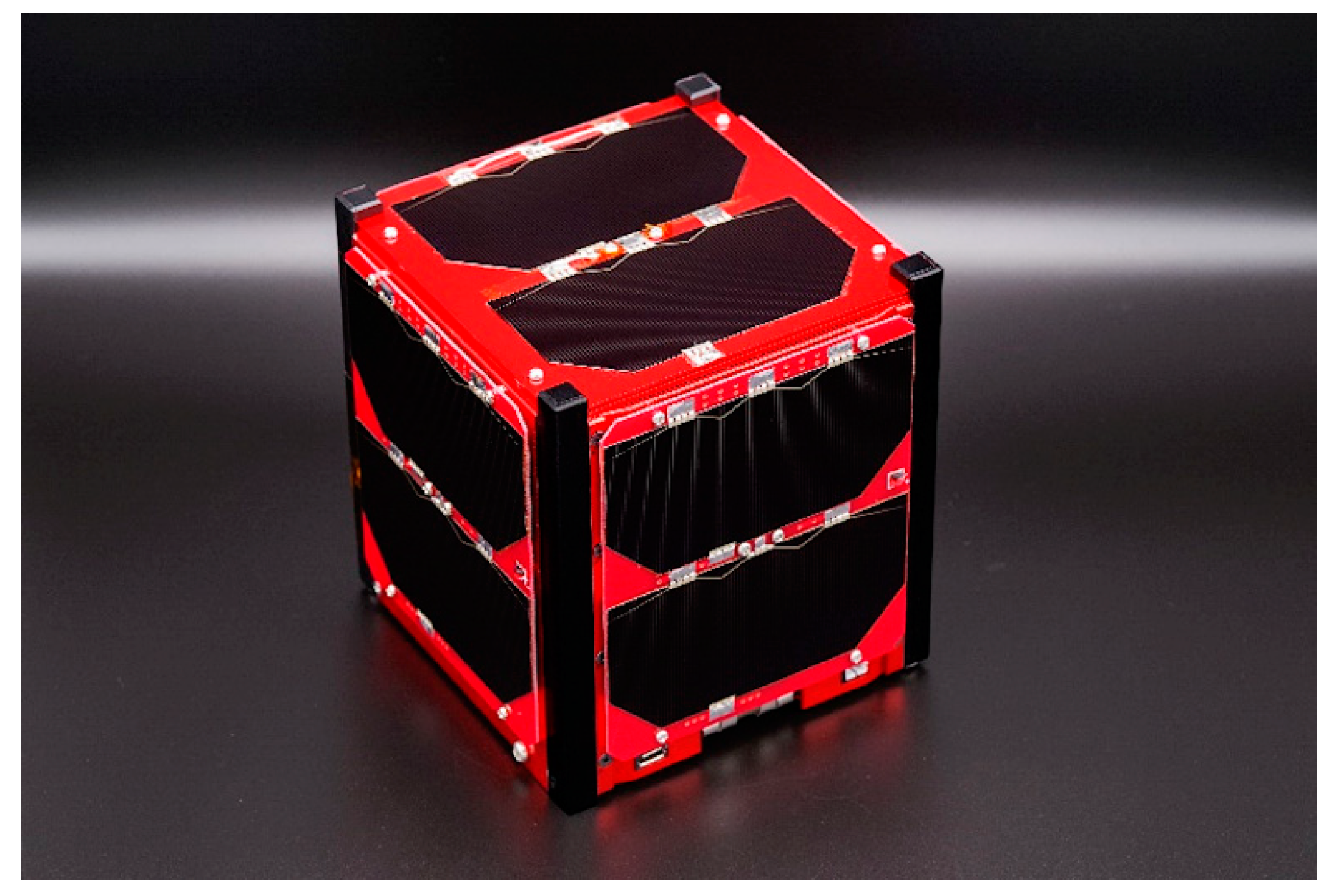
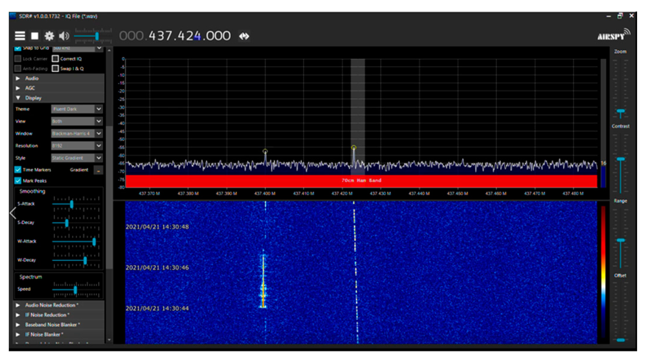
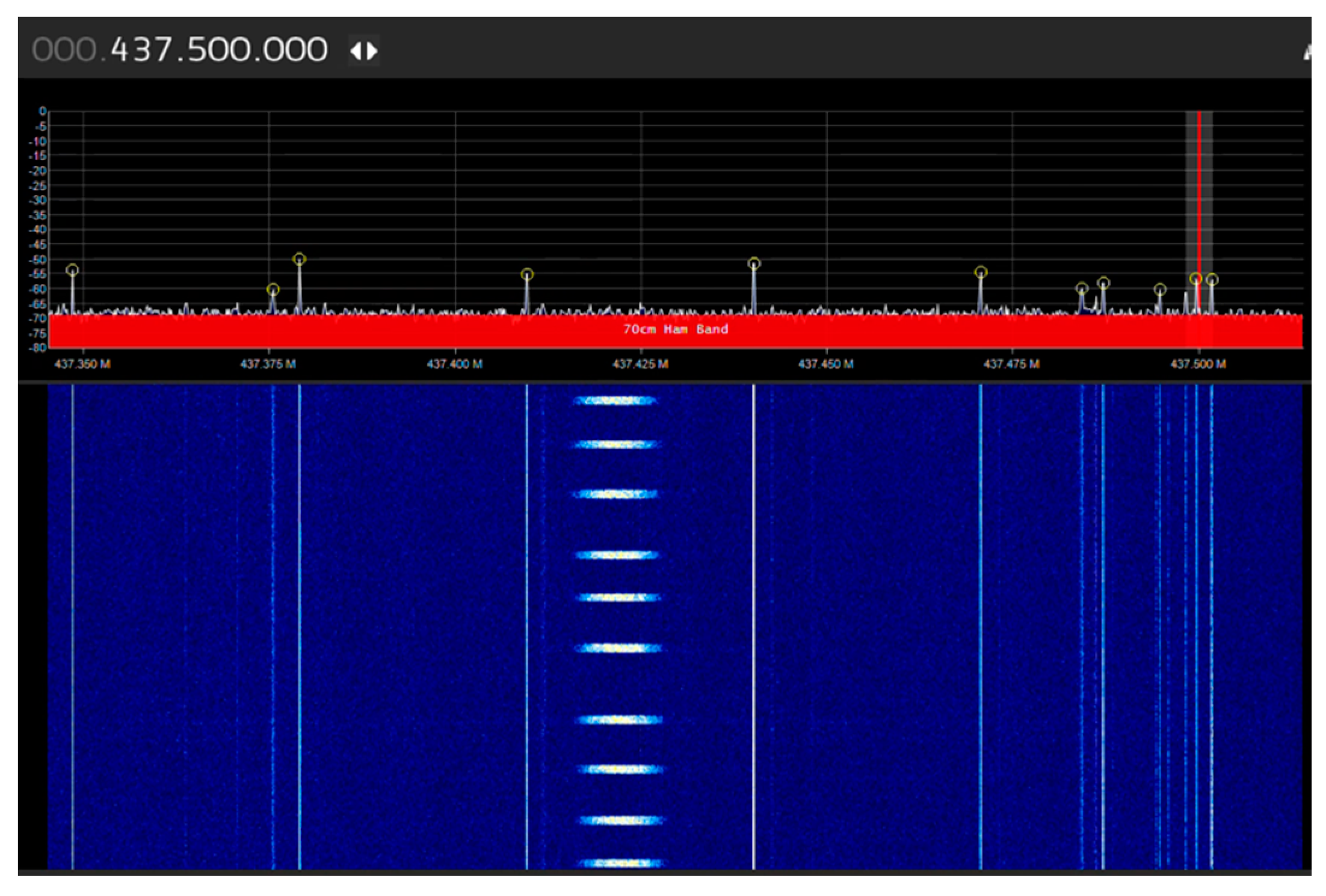
Based on the test results, we developed a satellite component and demonstrated its in-orbit performance as the communication module of an LEO CubeSat (WARP-01) at 400 km altitude. Hence, normal operation was confirmed for both CW and FSK signals, and space utilization of the consumer communication IC was shown to be possible.
The key outcome was a successful space mission involving the transceiver with the consumer communication IC, which was achieved following sufficient space environment tests, i.e., radiation tolerance and Doppler frequency tests. To exploit the CubeSat mission, rapid development is crucial; therefore, the use of consumer parts and products is unavoidable, not only in our work but for future projects as well. As it is difficult to perform environmental tests, such as radiation tolerance in several institutions, the sharing of information and space application results is crucial. The methodology presented in this paper can be helpful for the advanced evaluation of electrical parts and can contribute to more flexible and advanced system designs using newly introduced devices. As a limitation, production lot differences exist between the test and onboard devices; however, the usage of up-to-date consumer products can enhance and broaden research opportunities compared to persistence with out-of-date products.


 ,
, 


