Article

Resilient Multi-Source Integrated Navigation Method for Aerospace Vehicles Based on On-Line Evaluation of Redundant Information

1
Navigation Research Centre, College of Automation Engineering, Nanjing University of Aeronautics and Astronautics, Nanjing 211106, China
2
College of Astronautics, Nanjing University of Aeronautics and Astronautics, Nanjing 211106, China
*
Author to whom correspondence should be addressed.
Submission received: 2 June 2022 / Revised: 11 June 2022 / Accepted: 20 June 2022 / Published: 22 June 2022

Abstract

:
Aerospace vehicle navigation systems are equipped with multi-source redundant navigation sensors. According to the characteristics of the above navigation system configuration, building a resilient navigation framework to improve the accuracy and robustness of the navigation system has become an urgent problem to be solved. In the existing integrated navigation methods, redundant information is only used for backup. So, it cannot use the redundant navigation information to improve the accuracy of the navigation system. In this paper, a resilient multi-source fusion integrated navigation method based on comprehensive information evaluation has been proposed by combining of qualitative analysis and quantitative analysis in information theory. Firstly, this paper proposes a multi-layer evaluation framework of redundant information and carries out quantitative analysis of redundant information with the information disorder analysis theory to improve the reliability of the navigation system. Secondly, a navigation output effectiveness evaluation system has been established to analyze the output of heterogeneous navigation subsystems qualitatively to improve the fusion accuracy. Finally, through the mutual correction of multi-level information evaluation results, the error decoupling between the output parameters of heterogeneous navigation sensors has been realized to improve the robustness of the system. The experimental results show that the method proposed in this paper can adaptively allocate and adjust the weight of navigation information at all levels, realize the “non-stop” work of the navigation system and enhance the resilient of the navigation architecture. The navigation accuracy is improved compared with the existing multi-source fusion algorithm, which reflects the reliability and robustness of this algorithm.

1. Introduction

At present, countries around the world are actively exploring space. Therefore, the invention of safe and reliable transportation system that can realize the round-trip between space and land has become a primary task. It is also an important premise for human beings to make large-scale use of space [1,2,3]. In recent years, the research of aerospace vehicles has gradually become popular. An aerospace vehicle is a kind of reusable aircraft with horizontal take-off and landing. It can fly in the two spaces of aviation and aerospace, so it can reduce the cost of round-trip transportation between space and earth significantly, which has high application value. As countries around the world regard aerospace as a new generation of strategic development field, the research of aerospace vehicles will also be paid attention to by countries all over the world.
Different from traditional aircrafts, aerospace vehicles break through the limitations of traditional aircrafts. They have the characteristics of multiple mission, multiple working modes, and high-speed maneuvering. At the same time, they also have the advantages of reuse and rapid launch [4]. At present, the representative achievements in the field of aerospace vehicle research include the United States’ X-37B, Russia’s “multi-purpose aerospace system”, Germany’s “Sanger”, Britain’s “Skylon”, and so on [5]. Among them, except that the US X-37B has completed the scheduled mission and returned successfully, most of the other research are still in the stage of research and development. The main bottleneck restricting the development of this technology is the complex motion characteristics of aerospace vehicles. In the whole flight process from take-off to landing, aerospace vehicles must go through five main stages: take-off, orbit entry, in orbit, flexible orbit change, and high-speed re-entry [6]. Complex motion characteristics bring a great challenge to the existing navigation, guidance, and control technology. As an important part of GNC technology, navigation technology directly affects the accuracy of guidance and control loop. Therefore, advanced navigation technology has become one of the key technologies that need to be broken through urgently, and it is also a prerequisite for the safe execution of missions with aerospace vehicles.
To realize the cross-space flight of aerospace vehicle and measure its navigation parameters in each flight stage accurately, it is necessary to use multiple types of navigation sensors [7]. Therefore, build a high-precision, highly reliable, and resilient multi-source fusion navigation system architecture is the primary way to solve the problem. Public information shows that the aerospace vehicle navigation system adopts multi-source redundancy configuration scheme to meet its system fault tolerance requirements. Therefore, based on inertial navigation system, according to the environmental characteristics of different flight stages, different types of auxiliary navigation sensors [8] are used to improve the reliability of the navigation system has become the consensus of researchers, such as satellite navigation system [9], celestial navigation system [10], atmospheric altitude measurement system, synthetic aperture radar, and so on [11]. The key of aerospace vehicle navigation system to meet its high-precision and reliable measurement requirements lies in: How to fuse multi-source navigational information that has significant spatiotemporal heterogeneity. Different navigation sensors in aeronautical and astronautics flight environment have significant differences in the measurement principles and mathematical modelling methods, and the output navigation parameters are also in different coordinate systems. It reflects the heterogeneity in spatial measurements. At the same time, different navigation sensors also have heterogeneous characteristics in time. Their sampling interval varies with different flight phases and environments. In addition, the harsh flight environment such as high speed and high dynamics of aerospace vehicle also brings challenges to the reliable measurement of navigation sensors. Compared with traditional aircraft, the flight environment faced by aerospace vehicles is more complex and harsher. The conventional single combination mode is difficult to correct the navigation system error reliably and difficult to obtain high-precision navigation information.
Therefore, in the multi-modal flight process of aerospace vehicles, advanced and effective information processing algorithms need to build a resilient multi-source navigation sensor fusion architecture and fuse heterogeneous navigation information to meet the needs of autonomous and reliable navigation. “Resilient” is a frequent concept in the field of PNT in the United States in recent years. Different departments in the United States regard “Resilient” as an important PNT capability from different aspects. This capability is juxtaposed with the capability characteristics of precision, rapid development, reliability, complementarity, and robustness. Academician Yang Yuanxi of China believes that resilient frame must have redundant information at first, otherwise, there can be no “resilient” choice [12]. The basic starting point of resilient PNT is that any single PNT information source may have risks. Therefore, the utilization of “redundant” PNT information sources by other means is very important. It can be seen that integrating the resilient design idea into the architecture design of aerospace vehicle navigation system can well meet the characteristics of redundant configuration of its navigation sensors.
In terms of existing navigation system integration architecture design, Gao has proposed the two-level structure for the fusion of local state estimates and then to obtain the global optimal state estimation [13]. Mostafa has proposed that the adaptive data sharing factor combined filter (DSFCF) is used as integrated navigation method [14]. At present, the design of fusion architecture is mainly considered from one of the aspects of accuracy or reliability, which leads to the fact that the fusion architecture does not have resilient ability and is difficult to adapt to the complex flight environment of aerospace vehicles. In recent years, Virginia Tech designed the Virginia Tech Formation Flying Testbed (VTFFTB), a GPS-based hardware-in-the-loop (HIL) simulation testbed for dual-satellite formation flying [15]. The platform provides a new idea for the verification of redundant architecture. In addition, different navigation sensors have different statistical characteristics of noise, which makes it difficult for the existing fusion methods to realize the high-precision fusion of multiple types of navigation sensors information. At the same time, sensors that output the same type of navigation parameters, such as GPS and SAR, they can all output position information, but the accuracy of their output navigation parameters are also different due to the different working principles. Therefore, the existing federated filter composed of fixed coefficients cannot meet the accuracy requirements of aerospace vehicle navigation system. In addition to the architecture design, many researchers have also recently studied the algorithm of multi-source fusion navigation. Zhou has proposed a new algorithm, the so-called constrained adaptive robust integration Kalman filter (CARIKF) is presented, which implements adaptive integration upon the robust direct fusion solution [16]. Wang has proposed the algorithms of the navigation data fusion and the obstacle avoidance [17]. As can be seen from the above analysis, according to different practical application scenarios, selecting different navigation sensors to build a multi-source fusion navigation system is becoming an important way to improve the reliability and accuracy of the system. However, the current fusion algorithms generally take the single configuration of navigation sensors as the research object. When the carrier is configured with redundant navigation sensors, the above algorithms need to build multiple navigation subsystems and filters, resulting in complex system calculation and low efficiency.
The flight range of aerospace vehicle is wide and the diverse flight environment will cause complex motion characteristics undoubtedly. At the same time, the bad flight environment such as “Black-out” area during flight may lead to the failure of the navigation sensor of the aerospace vehicle. Therefore, the design of aerospace vehicle multi-source fusion navigation system must also meet the requirements of fault tolerance. This is also an important performance that the navigation system has the ability of resilient integration. In this field, many scholars have also carried out corresponding research. Xu has proposed a method called Isolation and Repair Plan Failures (IRPF) for a spaceship with durable, concurrent, and resource-dependent actions [18]. Xu has proposed that extracts the features with various scales, which contain both the local and the general information of the signal sequence, for making a comprehensive and precise classification and realize fault detection [19]. Li has designed a fault detection architecture applied to INS/ADS with a time-offset, which solves the problem of the high PFA of INS/ADS fault detection under a time-offset [20]. Lyu has proposed that use the knowledge of the thrust model to generate an analytical redundancy-based fault diagnosis approach for altitude estimation [
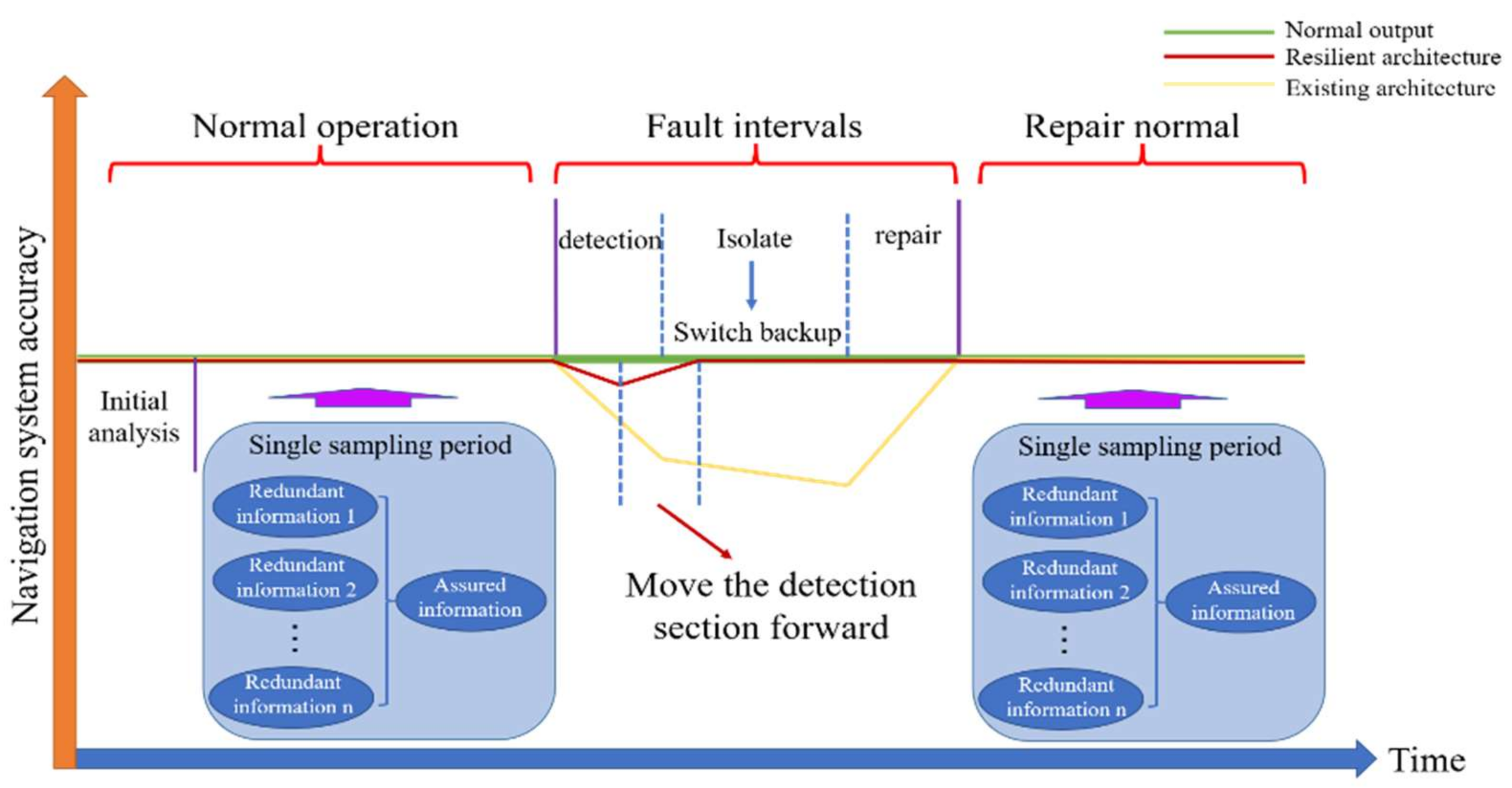
21]. From the above research, the fault-tolerant design is an important way to improve the reliability of the navigation system. However, the current fault-tolerant algorithm of navigation system mainly depends on the navigation subsystem composed of inertial navigation and other navigation sensors, and constructs the fault detection equation on this basis, which will lead to the efficiency reduction in the whole multi-source fusion navigation system. At the same time, the above algorithm usually has time delay when detecting the soft fault of navigation sensor, resulting in the fault polluting the main fusion system, and further polluting other healthy navigation subsystems through the feedback of the main fusion system to reduce the reliability of the whole system. Different from the general aircraft, the navigation sensor configuration of aerospace vehicle is not only multi-source, but also redundant on the same kind of navigation sensor. Therefore, how to make full use of the redundant navigation sensors information is very important. This paper combines of sensor fault-tolerant design and navigation subsystem fault-tolerant design to make the fault detection interval move forward and improve the reliability and robustness of multi-source redundant navigation system.
Aiming at the problems of complex flight environment and changeable motion characteristics of aerospace vehicle, which lead to the decline of accuracy, low fault tolerance and poor robustness of existing multi-source fusion navigation algorithms. This paper has proposed a resilient multi-source integrated navigation method for aerospace vehicles based on on-line evaluation of redundant information. The main innovations of this paper are as follows:
(a)
We have designed a multi-level evaluation method of redundant information and use the information disorder analysis theory to carry out the quantitative analysis of redundant information of navigation sensor. The online adaptive weight allocation of the same type of redundant navigation sensors is realized, which solves the problem of filter instability caused by switching backup navigation sensors when the primary sensor fails, the navigation system realizes the “non-stop” work at the sensor level and improves the reliability.
(b)
Secondly, the output effectiveness evaluation system of navigation subsystem has been established. According to the working principle, working characteristics and other factors of different types of navigation sensors, qualitative analysis of subsystem layer has been carried out, which solve the problem that different types of navigation sensors are difficult to unify the evaluation criteria for information fusion due to different accuracy.
(c)
Finally, through the mutual correction of multi-level information evaluation results, the error decoupling between the output parameters of heterogeneous navigation sensors is realized to improve the robustness of the system.
Based on the existing multi-source fusion navigation system design ideas, the fusion architecture and algorithm has been proposed in this paper is combined with the characteristics of multi-source redundant navigation sensor configuration of aerospace vehicle and improve the fusion architecture with resilient ability. On this basis, a quantitative evaluation framework is designed for the output of the same type of navigation sensors in the sensor layer. According to use the redundant sensor information and the theory of information disorder analysis, different weights are given to the same type of navigation sensor outputs and the navigation parameters output of this type of sensors is weighted calculation. At the subsystem layer, the navigation subsystem is constructed by using the navigation parameters output from the sensor layer. The hierarchical analysis is carried out for the working characteristics of heterogeneous navigation sensors and the initial weights of heterogeneous navigation sensors that output the same type of navigation parameters are given. At the same time, combined with quantitative analysis, the quantitative analysis weights and qualitative analysis weights are fused to realize the adaptive adjustment of the fusion weights of each sub filter in the main fusion layer. Finally, the design of resilient multi-source redundant navigation system is completed. This paper designs the fusion algorithm from the dimensions of navigation system accuracy, reliability and fault tolerance. The method can meet the requirements of high precision and high reliability of aerospace vehicle navigation system, and is of great significance to the further engineering of aerospace vehicle research.

2. Multi Source Navigation Information Resilient Fusion Architecture

Measuring resilient is a key component of designing resilient architecture. Quantitative evaluation theory is needed to evaluate the effectiveness of various resilient architecture designs and compare them with each other [22]. In the multi-source navigation system of aerospace vehicles, due to the difference of the applicable objects of the resilient architecture, quantitative evaluation cannot meet the needs of reliable measurement of heterogeneous information. Therefore, it is also necessary to carry out qualitative evaluation of the resilient architecture design according to the working characteristics of heterogeneous navigation sensors, to meet the reliable output of aerospace vehicle navigation system in complex flight environment.
As shown in Figure 1, the system architecture is an open architecture, so, the redundant and diversified navigation information sources must be ensured in the architecture to further improve the robustness of the system.

2.1. Resilient Fusion Architecture Design

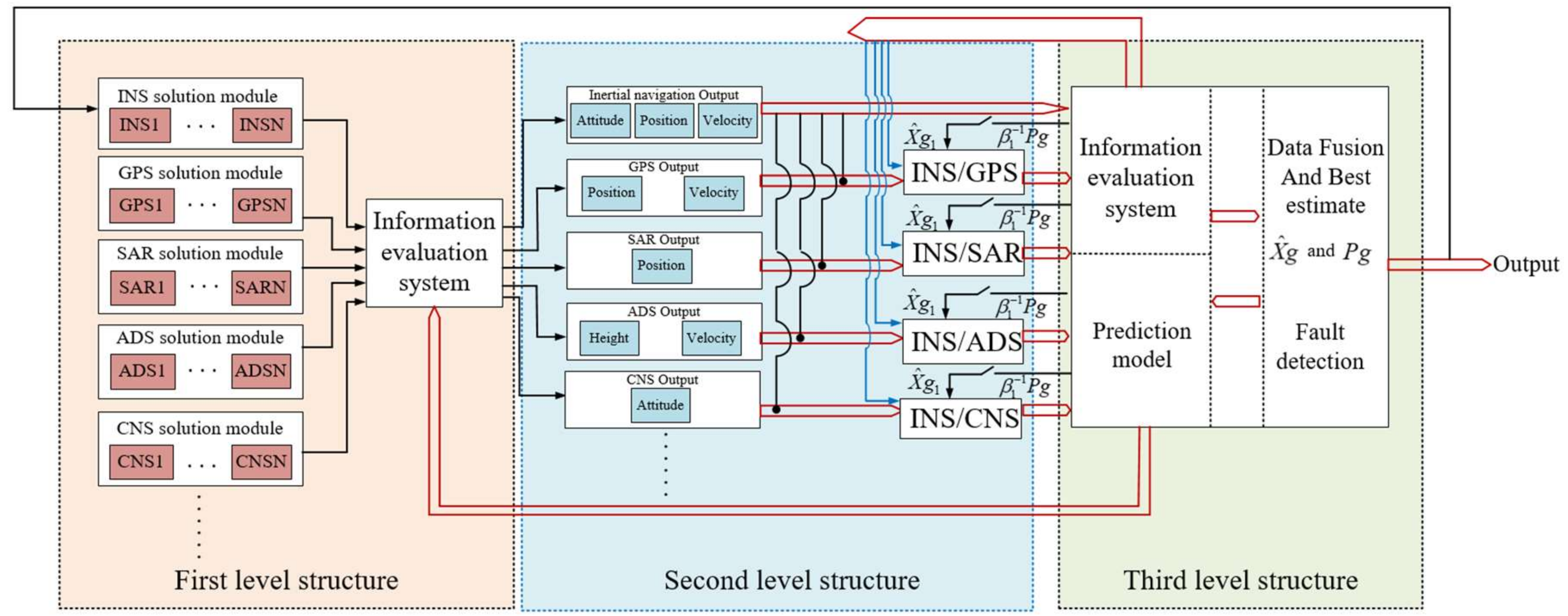
Due to the differences in the measurement principle and application scope of different navigation sensors, and considering the complex flight characteristics of aerospace vehicles, it is very easy to bring navigation sensor faults. Therefore, the architecture design of multi-source navigation system for aerospace vehicle must fully consider the output characteristics of various navigation sensors in different flight stages, deeply mine the information characteristics of navigation parameters. According to integrate the idea of resilient design and carry out quantitative evaluation to enable the navigation system have resilient self-repair capability in case of some sensor failures and realize the optimal output of navigation parameters. On this basis, the performance of different navigation sensors is qualitatively evaluated, at the same time, we have established the effectiveness evaluation system of navigation subsystem. Finally, a high-precision and reliable fusion architecture has been built. The architecture design diagram of resilient multi-source integrated navigation system for aerospace vehicle based on on-line evaluation of redundant information designed in this paper is shown in Figure 2.
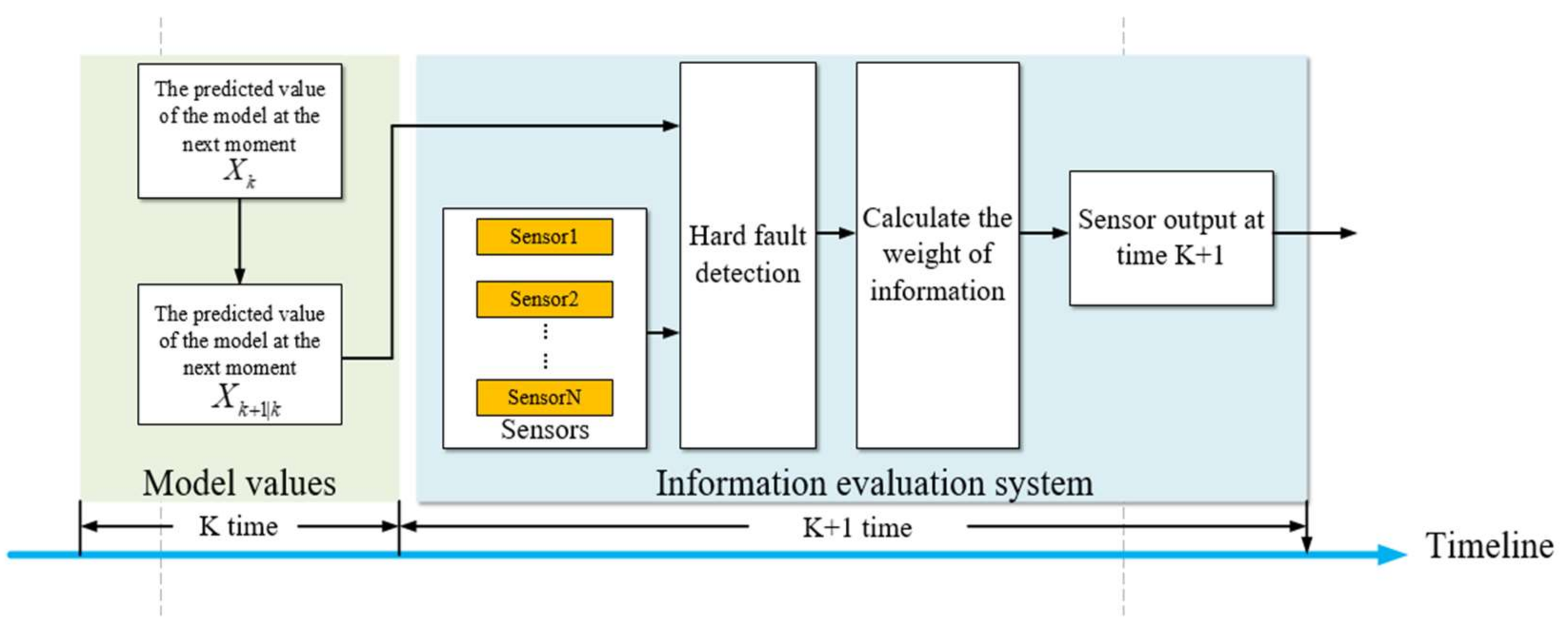
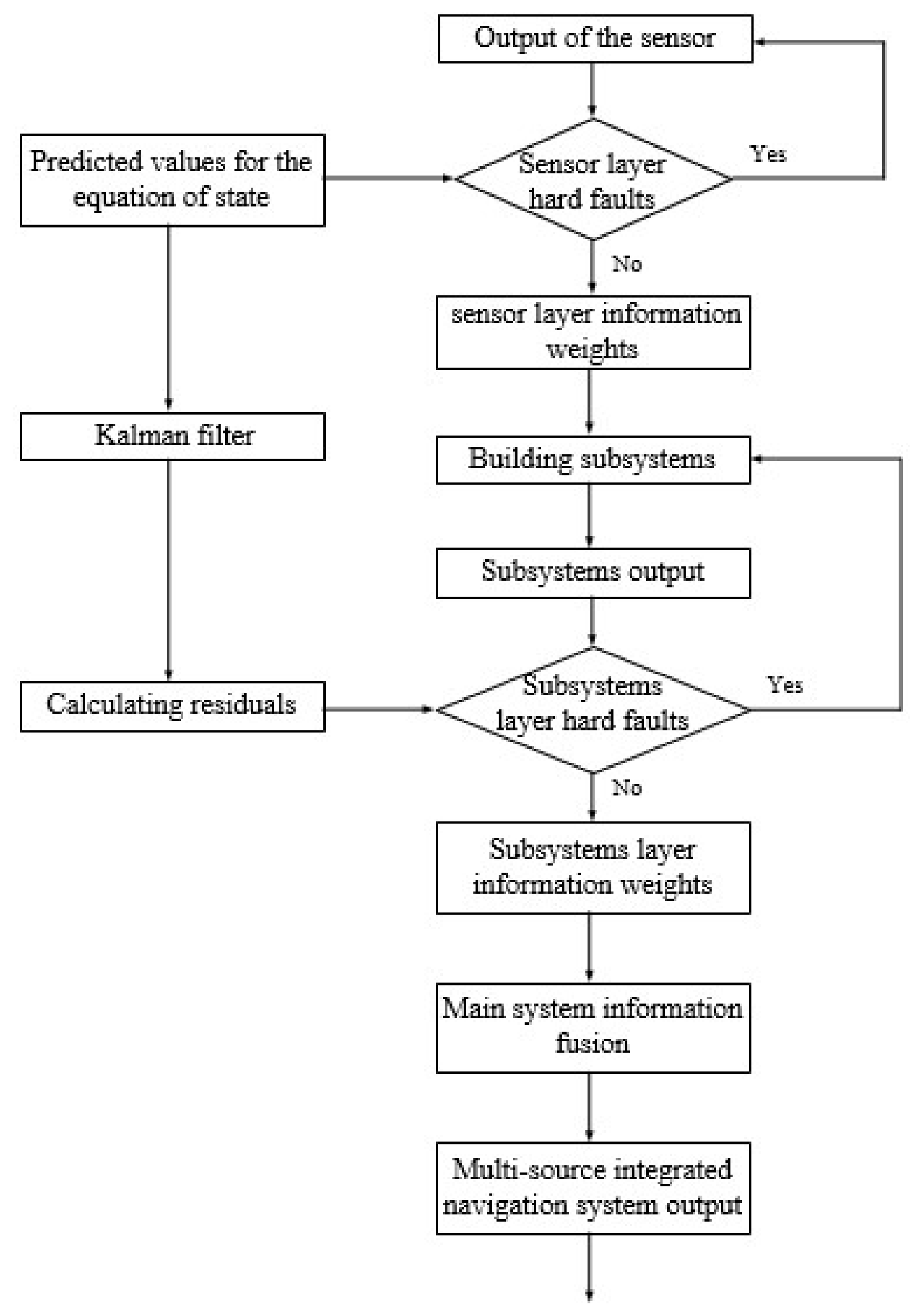
The above structure divides the aerospace vehicle navigation system into three levels. The first level structure is composed of various redundantly configured navigation sensors. Among them, taking inertial navigation as the reference navigation system to outputs the complete navigation parameters. Other navigation sensors output a part of navigation parameters and input the parameters to the on-line information evaluation system. In this system, combining with the output of navigation sensor and the one-step prediction value calculated by the state equation of navigation subsystem, hard fault detection is carried out. Then, according to the information disorder degree analysis theory, different weights are given to the navigation information contained in it, to realize the quantitative evaluation of sensor level information and fuse it to the second level navigation subsystem level.
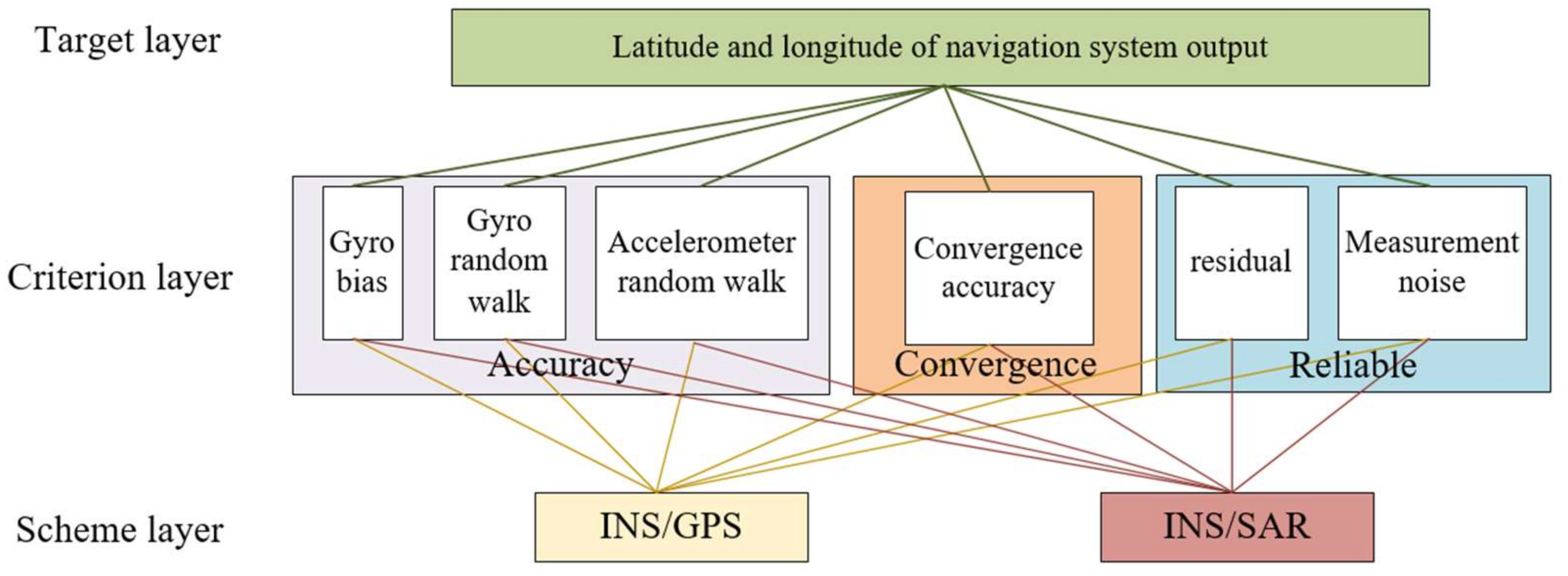
The second level structure consists of different navigation subsystem. Similarly, the quantitative evaluation of the navigation subsystem shall be carried out first. Different from the sensor level, the redundant information here refers to the navigation parameters output by different navigation subsystems, such as attitude, position, and velocity. Therefore, on the basis of quantitative evaluation, the effectiveness evaluation system of navigation results and the qualitative evaluation shall be researched in combination with the characteristics of different navigation sensors. Finally, the comprehensive information evaluation weight coefficient is formed, and the complete navigation parameters are calculated and output to the third level fusion architecture.
The third level structure is data master fusion. The optimal fusion is carried out according to the filtering results of each subsystem and its own filtering value. At the same time, the error decoupling between the attitude and position of the navigation system is realized by using the evaluation system, and the global optimal estimation value is obtained.

2.2. Establish System Model

In this paper, the east-north-up geographic coordinate system is used as the reference coordinate system for navigation calculation, which is recorded as n coordinate system. It is assumed that the gyroscope drift error is composed of random walk and white noise, the accelerometer error is random walk. The three-dimensional platform error angle ϕ e , ϕ n , ϕ u , three-dimensional velocity error Δ v e , Δ v n , Δ v u , three-dimensional position error Δ L , Δ λ , Δ h , three-dimensional random walk of gyroscope ε bx , ε by , ε bz ,   and three-dimensional random walk of accelerometer x , y , z . The above 15 variables constitute the state quantity of Kalman filter.
X = [ ϕ e , ϕ n , ϕ u , Δ v e , Δ v n , Δ v u , Δ L , Δ λ , Δ h , ε bx , ε by , ε bz , x , y , z ] T
In (1), subscripts e , n , u respectively indicate east, north, and up directions.
The system state equation is constructed as follows:
X ˙ = F t X t + G t W t
In (2) , F t is the system matrix; G t is the system noise matrix; W t is the system noise vector.
According to the error equation of inertial navigation system and the error model of inertial instruments in geographical coordinate system, the corresponding system matrix can be obtained as follows:
F t = F N ( t ) 9 × 9 F S ( t ) 9 × 6 0 6 × 9 0 6 × 6
In (3), F N ( t ) 9 × 9 is the 9 × 9 -dimensional basic navigation parameter matrix, F S ( t ) 9 × 6 is the conversion matrix between the 9-dimensional basic navigation parameters and the 6-dimensional inertial device errors. Its specific form is as follows:
F S ( t ) 9 × 6 = C b n 0 3 × 3 0 3 × 3 C b n 0 3 × 3 0 3 × 3 9 × 6
In (4), C b n is the attitude conversion matrix from body coordinate system to the geographic coordinate system.
The system noise matrix G t is:
G t = C b n 0 3 × 3 0 3 × 3 0 6 × 3 0 6 × 3 0 6 × 3 0 3 × 3 I 3 × 3 0 3 × 3 0 3 × 3 0 3 × 3 I 3 × 3
The system noise vector W is:
W = ω ε x ω ε y ω ε z ω n x ω n y ω n z f n x f n y f n z
After discretizing (2), the discrete state equation of the system can be obtained as follows:
X k = Φ k , k 1 X k - 1 + Γ k - 1 W k - 1
In (7), X k is the state quantity at moment k , X k - 1 is the state quantity at moment k 1 , Φ k | k 1 is the system state transfer matrix from moment k 1 to moment k , Γ k - 1 is the corresponding discrete system noise matrix, and W k - 1   is the system noise at moment k 1 .
Φ k , k 1 = n = 0 F t k T n / n !
Γ k 1 = n = 1 1 n ! F t k T n 1 G t k T
T is the iteration period.
State one-step prediction:
X ^ k | k 1 = Φ k | k 1 X ^ k 1
Under the current navigation technology conditions, the sensor configuration of aerospace vehicle navigation system is based on inertial navigation system (INS), assisted by variety of navigation measurement sensors, such as global satellite navigation system (GNSS), celestial navigation system (CNS), automatic dependent surveillance (ADS), synthetic aperture radar (SAR), etc. Combining with the above analysis, the measurement equations of each navigation subsystem are established:
Z k = H k X k + N k
In (11), The measurement information in the measurement equation consists of the difference in velocity, position, and attitude between the INS output and other sensors output.   N k is the measurement noise matrix.

3. Navigation Information Comprehensive Evaluation System

3.1. Quantitative Evaluation Framework of Redundant Navigation Information

According to Figure 2, the multi-source fusion navigation system of aerospace vehicle can be divided into three levels: navigation sensor level, navigation subsystem level, and main fusion system level. In the first level, the reliability of navigation parameter output at this level is improved through the quantitative evaluation of sensors output information. The specific process is shown in Figure 3.

3.1.1. Outlier Detection of Redundant Navigation Information

The existing outlier detection algorithms for navigation information are mainly based on the characteristics of the integrated navigation system of aerospace vehicle, the residual value based on Kalman filter can be calculated by constructing the sub filter of the navigation system, then, the residual chi square method can be used to detect and identify the hard fault. If it is judged that there is no fault in the subsystem, send its filtered value to the qualitative evaluation system. If a fault is detected in the output information of the subsystem, the subsystem will be isolated immediately, and the federated filter structure will be reconstructed by using the remaining navigation subsystems. However, at the sensor level, the navigation subsystem has not been constructed, so the residual cannot be calculated. Therefore, this paper uses the one-step prediction value of state quantity to identify and detect the hard fault output at the sensor level.
The output of a navigation sensor containing general measurement noise is y t , which can be expressed as:
y t = y + N c
In (12), y is the true sensor output and N c is the measurement noise.
Let the output of navigation sensor containing a hard fault be y e , which can be expressed as:
y e = y + N e
In (13), N e is the measurement noise containing the hard fault.
From Figure 3, at moment k , the k + 1 moment state quantities X k + 1 | k can be predicted with (10), and in combination with (11), the predicted value of the quantity measurement at k + 1 time Z ˜ k + 1 | k can be calculated. Taking (10) into (11), the actual output of the measurement at moment k is obtained as Z k + 1 | k . Therefore, the difference between the predicted and actual values of the measurement output at moment k + 1 is further obtained as E k + 1 | k :
E k + 1 = Z ˜ k + 1 | k Z k + 1 | k
From (12) and (13), it follows that:
N e N c
Therefore, hard faults at sensor level can be identified and detected based on fault determination criteria.

3.1.2. Evaluation Method of the Disorder Degree of Information

In the sensors level, after the hard fault detection of navigation information, the navigation information without hard fault is classified. Among them, the outputs of the same type of navigation sensor at k + 1   time are summarized into one class, defined as ϑ * , where denotes a different type of navigation sensor. The ϑ * contains all the information output by that type of navigation sensor. It is worth noting that the soft fault will cause a change in the degree of disorder of the information output by the navigation sensor. Therefore, in order to achieve the identification and isolation of soft faults at that level, the degree of disorder of the information system consisting of that group of information needs to be evaluated.
Assuming that the system can be in different states and that each state occurs with probability ρ i i = 1 , 2 , n , the degree of disorder of the system information obtained for ϑ * is defined as ζ . ζ can be expressed as:
ζ = i = 1 n ρ i ln ρ i
When the same type of navigation sensor is in the same state, the maximum value of ζ is:
ξ m a x = ln n
The ϑ * contains u t h sliding window information of a certain type of navigation sensor, there are v t h navigation sensors of the same type, at this point the matrix l can be constructed as:
l = l 11 l 12 l 1 v l 21 l 22 l 2 v l u 1 l u 2 l u v
Correcting (18) for negative indicators gives:
l ˜ i j = max l 1 j , l u j l i j max l 1 j , l u j min l 1 j , l u j
The non-negative matrix l ˜ is obtained from(19):
l ˜ = l ˜ 11 l ˜ 12 l ˜ 1 v l ˜ 21 l ˜ 22 l ˜ 2 v l ˜ u 1 l ˜ u 2 l ˜ u v
Calculating the probability matrix ρ , each element in ρ can be expressed as:
ρ i j = l ˜ i j i = 1 u l ˜ i j
Based on (21), the ζ j contained in the j t h parameter of the u t h navigation sensor is calculated to give:
ζ j = 1 ln u i = 1 u ρ i j ln ( ρ i j )   j = 1 , 2 , , v
Combining (22) to calculate effectiveness indicators η j :
η j = 1 ζ j
Combining (23) to normalize validity indicator η j gives weighting indicator ω s :
ω s = 1 η j v j = 1 v η j   j = 1 , 2 , v
Using (24), the information weights of the different types of redundantly configured navigation sensors in the first level are obtained.
After information evaluation, the output of y t is Y o :
Y o = ω s y t
In (25), y t is calculated by multiplying the output of navigation sensors of the same type by the weight after quantitative evaluation.

3.2. Qualitative Evaluation of Redundant Navigation Information

From the previous section introduction, each navigation sensor can be given a weight, and this weight can be adaptively resilient adjusted according to the information contained in the sensor output. Therefore, even if a sensor fails, this type of navigation sensor can still maintain high-precision output without data jump caused by sensor switching. On this basis, we can further conduct qualitative evaluation of the navigation subsystem to improve the accuracy and reliability of the system.

Effectiveness Evaluation System of Navigation Subsystem

Among the different navigation sensors configured for aerospace vehicle, some sensors will output the same type of navigation parameters. For example, GPS and SAR will output longitude and latitude. However, due to their different working principles, working methods and adaptive environments, their accuracy during normal operation will also be different. Therefore, based on the analysis in the previous section, according to the characteristics of different navigation sensors, a navigation subsystem effectiveness evaluation system in line with the actual application environment has been established to improve the system accuracy.
The evaluation indexes of navigation subsystem filters can be generally divided into three categories, including inertial navigation system evaluation, measurement sensor evaluation and filter convergence evaluation, and each type of evaluation index can be subdivided [23]. Among them, inertial navigation system evaluation system mainly includes gyro bias, gyro random walk and accelerometer random walk, The measurement sensor evaluation system mainly includes residual error and measurement noise, and the convergence evaluation system mainly includes convergence accuracy and convergence time. Of course, different evaluation indexes can be selected according to the actual navigation sensors, but the method has been proposed in this paper is general. Combined with the engineering needs of aerospace vehicle navigation subsystem and according to the output characteristics of different navigation subsystems, this paper selects appropriate indicators and establishes its effectiveness evaluation system, as shown in Figure 4.
According to Figure 4, the gyroscope zero bias coefficient is C 1 , the gyroscope random wander coefficient is C 2 , the accelerometer random wander coefficient is C 3 , the convergence accuracy coefficient is C 4 , the residual coefficient is C 5 , the measurement noise coefficient is C 6 , and the coefficient matrix is C :
C = C 1 C 2 C 3 C 4 C 5 C 6
Compare the elements in matrix C , calculate their influence factors on the longitude and latitude output Z of the navigation subsystem, and then use the influence factors to establish the comparison result matrix A = a i j n × n , and we can obtain:
a i j > 0 a i j = 1 a j i i , j = 1 , 2 , n
The eigenvector η of the maximum eigenvalue λ m a x corresponding to the judgment matrix A in combination with (26) and (27) is expressed as:
η = η 1 , , η n T
When the left and right sides of matrix A are multiplied by the eigenvectors, respectively, we obtain the equation:
A η = η n
Then, A = a i j n × n can be expressed as:
A η = η 1 η 1 η 1 η 2 η 1 η n η 2 η 1 η 2 η 2 η 2 η n η n η 1 η n η 2 η n η n = η 1 η 2 η n η 1 η 2 η n = η n
Then, η is the eigenvector of matrix A ; n is the eigenvalue of matrix A under eigenvector η , that is, the sorting vector η is the eigenvector of judgment matrix A . The above judgment matrix A is a positive reciprocal matrix, which shall meet the consistency conditions, including: (a) The rank of matrix A is 1. (b) The maximum eigenvalue of matrix A is n .
According to Equation (29) and (30), we can obtain the maximum eigenvector of the judgment matrix A :
λ m a x = 1 n i = 1 n j = 1 n a i j η j η j
If and only if λ m a x = n , A is consistent matrix. The eigenvector corresponding to the maximum eigenvalue is used as the weight vector of the influence degree of the compared factor on a factor in the upper layer. The greater the degree of inconsistency, the greater the judgment error. Therefore, the inconsistency of matrix A can be measured by the value of λ m a x n .
Consistency test for (30), and calculating consistency test indicators C I :
C I = λ m a x n n 1
Comparison of average random consistency indicators R I and calculating the consistency ratio C R :
C R = C I R I
After passing the consistency test, the eigenvector η corresponding to the maximum eigenvalue λ m a x of the matrix A is the weight vector ω A S of this level. ω S A is the weight vector of the criterion layer A relative to the target layer S .
Based on Table 1, the weight vector ω B A of scheme layer B with respect to criterion layer A can be further calculated by combining (26)–(32), then using (33) to test the random consistency of layer B . From Table 1, we can calculate the total ranking of level B:
ω B S = ω A S ω B A = j = 1 m b 1 , j a j j = 1 m b 2 , j a j j = 1 m b n , j a j

3.3. Main Information Fusion System

After calculating the weight of the output characteristic parameters of the redundant navigation subsystem, the main information fusion is further carried out. Among the subsystems, the inertial navigation system is selected as the common reference system, and the sub filter is formed with other navigation subsystems to input their respective estimation information to the main filter. The main filter performs the optimal fusion of the input information of the sub filter, then the global optimal estimation based on all measurement information is obtained. The schematic diagram is shown in Figure 5.
In Figure 5, time updates are:
X i k / k 1 = Φ i k / k 1 X i k 1 P i k / k 1 = Φ i k / k 1 P i k 1 Φ i T k / k 1 + Γ i k 1 Q i k 1 Γ i T k 1
Measurement update is:
K i k = P i k / k 1 H i T k ( H i k P i k / k 1 H i T k + R i k ) 1 P i k / k = I K i k H i k P i k / k 1 I K i k H i k T + K i k R i k K i T k X i k / k = X i k / k 1 + K i k Z i k H i k / k X i k / k 1
The principles of information distribution are:
P i 1 k = β i P g 1 k X ^ i k = X ^ g k Q i 1 k = β i Q g 1 k   i = 1 , 2 , , N
Combining the output characteristic parameter weights ω S B of the redundant navigation subsystem, the value of β i in (37) is quadratically computed to calculate the new assignment factor μ i :
μ i = ω S B β i
where μ i satisfies the principle of conservation of information.
The flow chart of multi-source fault-tolerant robust filtering algorithm based on information evaluation proposed in this paper is shown in Figure 6.

4. Simulation Experiments

In this section, based on Monte Carlo simulation experiments are conducted to test the performance of the method proposed in this paper.

4.1. Simulation Parameter Setting

The initial latitude and longitude of the aerospace vehicle launch are 110 ° , 20 ° , 5000   m , the initial heading angle is 90 ° , the flight time is 1900   s , and the flight trajectory is shown in Figure 7. The trajectory contains the flight phases of the aerospace vehicle launch, climb, turn and re-entry.
The solution period for the strap-down inertial navigation system is 0.02   s and the filtering period is 1   s ; set the navigation sensor simulation parameters as shown in Table 2.
System noise variance:
Q = d i a g 0.01 / h 0.01 / h 0.01 / h 0.01 / h 0.01 / h 0.01 / h 1 × 10 4 g 1 × 10 4 g 1 × 10 4 g 2
For the redundant configuration scheme of navigation sensors, three groups of GPS and three groups of CNS are designed to provide redundant information of position and attitude, respectively. Among them, hard faults and soft faults are added to one group of GPS and one group of CNS respectively. The specific fault parameters are set as Table 3:
According to the evaluation index of the navigation subsystem analyzed in Figure 4, the initial value is given with the expert system. The results are shown in Table 4:
Combining (26)–(32) and Table 4, we can obtain:
B 1 = 1 1 1 1 , B 2 = 1 1 1 1 , B 3 = 1 1 1 1 , B 4 = 1 2 1 / 2 1 , B 5 = 1 5 1 / 5 1 , B 6 = 1 3 1 / 3 1
Then, the weight vector of the scheme layer with respect to the target layer is obtained as follows:
ω S B = ω S B 1 ω S B 2 ω S B 3 ω S B 4 ω S B 5 ω S B 6
In (41):
w S B 1 = 0.5 0.5 , w S B 2 = 0.5 0.5 , w S B 3 = 0.5 0.5 , w S B 4 = 0.6667 0.3333 , w S B 5 = 0.8333 0.1667 , w S B 6 = 0.75 0.25

4.2. Comparison of Simulation Results

In order to test the effectiveness of the multi-source redundant navigation sensor information evaluation algorithm proposed in this paper, three sets of GPS with redundant configuration are simulated according to the fault parameters set in Table 3. The results are shown in Figure 8:
In order to test the performance of the multi-source fault-tolerant integrated navigation method proposed in this paper on the basis of information evaluation, this paper selects two comparison algorithms, one is that each type of navigation sensor is configured with a single to form a federated filter for integrated navigation (FKF), and the other is that each type of navigation sensor is configured with redundancy. The performance of the same type of sensor is the same, and the fixed coefficient method is used for weight allocation (CFKF). The algorithm in this paper also adopts redundant configuration for each type of navigation sensor, and the performance of the same type of sensor is the same. The difference is that the information evaluation algorithm based on the combination of qualitative and quantitative information (IPFKF) proposed in this paper is used to adjust the distribution weight dynamically and adaptively. The simulation comparison results (Figure 9, Figure 10 and Figure 11) are as follows:
According to the simulation results in Figure 9, Figure 10 and Figure 11, the RMS statistics of the output error is carried out. The results are shown in Table 5:

4.3. Discussion of Results

According to Table 3 and Figure 8, the algorithm proposed in this paper can identify GPS hard faults and soft faults. In the hard fault time of 60 s–160 s, the weight of GPS1 is directly reduced to 0, and the weight of GPS1 is allocated by GPS2 and GPS3 to ensure the measurement accuracy. During the soft fault time from 660 s to 1040 s, the weight of GPS1 gradually decreases after 660 s, which is in line with the added soft fault form. Currently, the weight of GPS2 and GPS3 gradually increases. When the soft fault continues to end after 1040 s, the three GPS carry out weight distribution according to their measurement information.
Figure 9 is the comparison diagram of attitude angle error of navigation output. Algorithm of FKF only uses a single CNS for attitude calculation, so it is difficult to maintain high-precision output in case of failure, resulting in divergence of filtering results. Due to the redundant configuration of CNS, the CFKF algorithm can improve the attitude output accuracy in case of fault. However, due to its fixed coefficient allocation, the CFKF algorithm cannot adaptively adjust the coefficients according to the actual size of fault, resulting in the decline of filtering accuracy. The IPFKF algorithm proposed in this paper, due to the combination of quantitative evaluation and qualitative evaluation, can dynamically and adaptively adjust the information distribution weight coefficient according to the fault size, to better track the actual trajectory and improve the filtering accuracy. The filtering error is obviously less than that of the other two algorithms.
In addition, it is worth noting that in case of GPS soft fault, that is, within the range of the box line in the figure, the CFKF and FKF algorithm errors increase significantly, mainly because the CNS attitude calculation requires horizontal position information, so the position error will be coupled. Therefore, in case of GPS soft fault, the attitude output accuracy is also significantly affected. The IPFKF algorithm proposed in this paper, because the information evaluation is carried out level by level from the navigation sensor level, which ensures the accuracy and high precision of position information output, it is not affected in case of GPS soft fault, which reflects the robustness of this algorithm.
Figure 10 shows the comparison diagram of navigation output position error, which has the same change trend as the comparison curve of attitude output accuracy. Due to the configuration of a single navigation sensor, FKF has poor fault tolerance performance, and the position output error is significantly greater than the other two algorithms. Compared with CFKF algorithm based on fixed coefficient allocation, the output error of IPFKF is smaller and the filtering accuracy is higher. Among them, Figure 10c is the height error comparison diagram. Since the height information output of the three algorithms comes from the atmospheric data system and no fault is added, so the accuracy of the three algorithms is the same.
Similarly, when calculating the position of aerospace vehicles in the geographical coordinate system, it is necessary to use the attitude to construct the attitude transfer matrix from the geographical coordinate system to the earth coordinate system, so the attitude error will be coupled into the position error, In the CNS soft fault range outlined in Figure 10a,b, the errors of FKF algorithm and CFKF algorithm increase significantly, while the IPFKF algorithm proposed in this paper can maintain stability, which shows the robustness of this algorithm.
Figure 11 is the comparison diagram of navigation output velocity error. In this paper, the velocity is obtained by position, so its curve change law is the same as that of position error curve. However, there is no additional fault. Therefore, the east and north velocity errors estimated by FKF and CFKF algorithms are similar, while the IPFKF improves the estimation accuracy through error decoupling. The variation trend of the estimation error of the three algorithms in the up direction is consistent with that in the height.

5. Conclusions

In the research, we have found that the sensors of the aerospace vehicle navigation system adopt redundant configuration, but the existing integrated navigation fusion architecture is difficult to make efficient use of redundant information, which leads to the problem that the fusion architecture does not have the resilient. So, a resilient multi-source integrated navigation method for aerospace vehicles based on on-line evaluation of redundant information has been proposed to improve the fault tolerance and robustness of the navigation system.
Firstly, this paper designs a multi-level and resilient redundant navigation information fusion architecture. According to the characteristics of the aerospace vehicle navigation system, the whole system has been divided into sensor level, subsystem level and main fusion level. The traditional navigation system outlier detection time interval is moved forward through the idea of hierarchical, so as to improve the reliability of the whole navigation system and realize the “non-stop” operation of its navigation system under abnormal conditions of some sensors.
Secondly, this paper integrates quantitative analysis and qualitative analysis. At the sensor level, quantitative analysis is realized through the theory of information disorder. At the subsystem level, an initial effectiveness evaluation system is formed according to the working principles and characteristics of heterogeneous navigation sensors and in combination with the expert system. During the flight of aerospace vehicles, the evaluation system is improved online according to the quantitative analysis results, then, the weight distribution coefficient of the federated filter is adaptively adjusted to improve the accuracy of the navigation system.
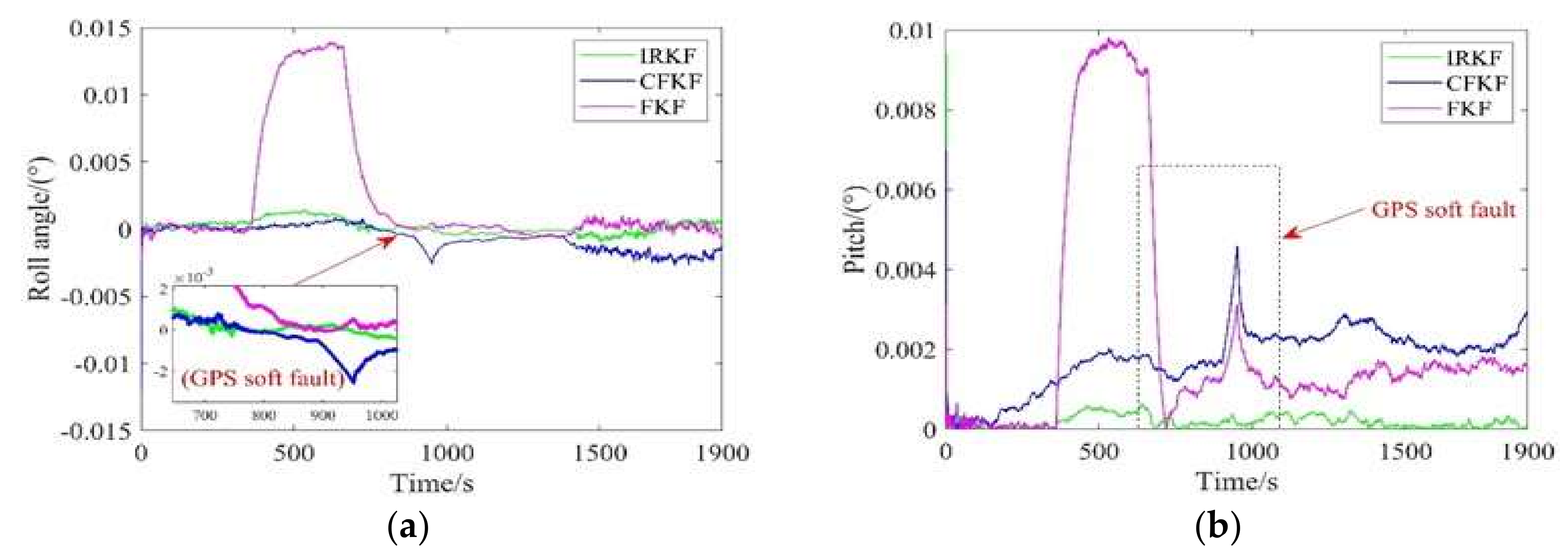
Finally, this paper uses the coupling relationship between the output parameters of heterogeneous navigation sensors and corrects each other through multi-level information evaluation to improve the robustness of aerospace vehicle navigation system. Particularly attention worthy is that the algorithm proposed in this paper can decouple the attitude error and position error in the configuration of multi-source redundant navigation system, which greatly reduces the probability of navigation system invalidation caused by various types of faults. The experimental results show that this algorithm can timely adjust the information output weight of each level in case of navigation sensor hard fault and soft fault, realize the “non-stop” operation of the navigation system in case of fault, and the accuracy is improved compared with the existing fault detection algorithms, which reflects the reliability and robustness of this algorithm.

Author Contributions

Conceptualization, J.K.; methodology, J.K.; software, J.K. and Z.X.; validation, J.K. and Z.X.; data curation, J.K. and R.W.; writing—original draft preparation, J.K., B.H. and Z.X.; writing—review and editing, J.K. and Z.X. All authors have read and agreed to the published version of the manuscript.

Funding

This research was funded by the National Natural Science Foundation of China (grant No. 61673208, 62073163, 61873125, 61533008, and 61533009), advanced research project of the equipment development (30102080101), Foundation Research Project of Jiangsu Province (The Natural Science Fund of Jiangsu Province, grant No. BK20181291, BK20170815, and BK20170767), the Aeronautic Science Foundation of China (grant No. 20165552043 and 20165852052), the Fundamental Research Funds for the Central Universities (grant No. NZ2020004, NZ2019007), Foundation of Key Laboratory of Navigation, Guidance and Health-Management Technologies of Advanced Aerocraft (Nanjing University of Aeronautics and Astronautics), Ministry of Industry and Information Technology, Jiangsu Key Laboratory “Internet of Things and Control Technologies,” and the Priority Academic Program Development of Jiangsu Higher Education Institutions, Science and Technology on Avionics Integration Laboratory. Supported by the 111 Project(B20007). It was also supported by Shanghai Aerospace Science and Technology Innovation Fund (SAST2019-085, SAST2020-073), Introduction plan of high-end experts (G20200010142), The National Key Research and Development Program of China (Grant No. 2019YFA0706003), and the Foundation of National Key Laboratory of Rotorcraft Aeromechanics (No.61422202111). The authors would like to thank the anonymous reviewers for their helpful comments and valuable remarks.

Institutional Review Board Statement

Not applicable.

Informed Consent Statement

Not applicable.

Data Availability Statement

Not applicable.

Conflicts of Interest

The authors declare no conflict of interest.

References

  1. Deneu, F.; Malassigne, M.; Le-couls, O.; Baiocco, P. Promising solutions for fully reusable two-stage-to-orbit configurations. Acta Astronaut. 2005, 56, 729–736. [Google Scholar] [CrossRef]
  2. Fujii, K.; Ishimoto, S. Research activities to realize advanced space transportation system. In Proceedings of the 16th AIAA/DLR/DGLR International Space Planes and Hypersonic Systems and Technologies Conference, Bremen, Germany, 19–22 October 2009; American Institute of Aeronautics and Astronautics Reston, VA, United States of America, 2009. [Google Scholar] [CrossRef]
  3. Qin, T.; Macdonald, M.; Qiao, D. Fully decentralized cooperative navigation for spacecraft constellations. IEEE Trans. Aerosp. Electron. Syst. 2021, 57, 2383–2394. [Google Scholar] [CrossRef]
  4. Zhao, Z.; Shang, H.; Dong, Y.; Wang, H. Multi-phase trajectory optimization of aerospace vehicle using sequential penalized convex relaxation. Aerosp. Sci. Technol. 2021, 119, 107175. [Google Scholar] [CrossRef]
  5. Cao, R.; Lu, Y.; Zhen, Z. Tracking control of transition window for aerospace vehicles based on robust preview control. Aerosp. Sci. Technol. 2021, 114, 106748. [Google Scholar] [CrossRef]
  6. Shao, X.; Shi, Y.; Zhang, W. Fault-tolerant quantized control for flexible air-breathing hypersonic vehicles with appointed-time tracking performances. IEEE Trans. Aerosp. Electron. Syst. 2021, 57, 1261–1273. [Google Scholar] [CrossRef]
  7. Simanek, J.; Kubelka, V.; Reinstein, M. Improving multi-modal data fusion by anomaly detection. Auton. Robot. 2015, 39, 139–154. [Google Scholar] [CrossRef]
  8. Chai, R.; Tsourdos, A.; Savvaris, A.; Chai, S.; Chen, C. Review of advanced guidance and control algorithms for space/aerospace vehicles. Prog. Aeronaut. Sci. 2021, 122, 100696. [Google Scholar] [CrossRef]
  9. Chen, K.; Zhou, J.; Shen, F.Q.; Sun, H.Y.; Fan, H. Hypersonic boost–glide vehicle strapdown inertial navigation system/global positioning system algorithm in a launch-centered earth-fixed frame. Aerosp. Sci. Technol. 2020, 98, 105679. [Google Scholar] [CrossRef]
  10. Ning, X.; Gui, M.; Fang, J.; Liu, G.; Dai, Y. A novel differential doppler measurement-aided autonomous celestial navigation method for spacecraft during approach phase. IEEE Trans. Aerosp. Electron. Syst. 2017, 53, 587–597. [Google Scholar] [CrossRef]
  11. Driedger, M.; Rososhansky, M.; Ferguson, P. Unscented Kalman filter-based method for spacecraft navigation using resident space objects. Aerosp. Syst. 2020, 3, 197–205. [Google Scholar] [CrossRef]
  12. Yuanxi, Y. Resilient PNT concept frame. Acta Geod. Cartogr. Sin. 2018, 47, 893–898. [Google Scholar] [CrossRef]
  13. Gao, B.B.; Hu, G.G.; Gao, S.S.; Zhong, Y.M.; Gu, C.F. Multi-sensor optimal data fusion for INS/GNSS/CNS integration based on unscented Kalman filter. Int. J. Control Autom. Syst. 2018, 16, 129–140. [Google Scholar] [CrossRef]
  14. Mostafa, M.Z.; Khater, H.A.; Rizk, M.R.; Bahasan, A.M. GPS/DVL/MEMS-INS smartphone sensors integrated method to enhance USV navigation system based on adaptive DSFCF. IET Radar Sonar Navig. 2019, 13, 1616–1627. [Google Scholar] [CrossRef]
  15. Peng, Y.; Scales, W.; Esswein, M.; Hartinger, M. Small satellite formation flying simulation with multi-constellation GNSS and applications to future multi-scale space weather observations. In Proceedings of the ION GNSS+; Institute of Navigation: Miami, FL, USA, 2019; pp. 2035–2047. [Google Scholar] [CrossRef]
  16. Wang, T.-c.; Tong, C.-S.; Xu, B.-L. AGV navigation analysis based on multi-sensor data fusion. Multimed. Tools Appl. 2018, 79, 5109–5124. [Google Scholar] [CrossRef]
  17. Hou, Z.; Li, Y.; Liu, J.; Li, G. Equality constrained robust measurement fusion for adaptive Kalman-filter-based heterogeneous multi-sensor navigation. IEEE Trans. Aerosp. Electron. Syst. 2013, 49, 2146–2157. [Google Scholar] [CrossRef]
  18. Xu, R.; Chen, C.; Lu, S.; Li, Z. Autonomous recovery from spacecraft plan failures by regulatory repair while retaining operability. Aerospace 2022, 9(1), 40. [Google Scholar] [CrossRef]
  19. Xu, H.W.; Lian, B.W. Fault detection for multi-source integrated navigation system using fully convolutional neural network. IET Radar Sonar Navig. 2018, 12, 774–782. [Google Scholar] [CrossRef]
  20. Li, Z.W.; Cheng, Y.M.; Wang, H.B.; Wang, H.X. Fault detection approach applied to inertial navigation system/air data system integrated navigation system with time-offset. IET Radar Sonar Navig. 2021, 15, 945–956. [Google Scholar] [CrossRef]
  21. Lyu, P.; Lai, J.; Liu, J.; Liu, H.H.T.; Zhang, Q. A Thrust model aided fault diagnosis method for the altitude estimation of a quadrotor. IEEE Trans. Aerosp. Electron. Syst. 2018, 54, 1008–1019. [Google Scholar] [CrossRef]
  22. Ming, F.; Zeng, A. Recent advancement and research on related issues for resilient PNT. J. Navig. Position. 2022, 4, 1–15. [Google Scholar] [CrossRef]
  23. Zhao, X.; Wang, Y.; Wang, S.; Zhang, J.; Yang, S. A quality evaluation method for integrated navigation information fusion algorithm. Chin. J. Inert. Technol. 2012, 20, 211–219. [Google Scholar] [CrossRef]
Figure 1. Resilient fusion architecture.
Aerospace 09 00333 g001
Figure 2. Architecture diagram of resilient multi-source integrated navigation system for aerospace vehicle.
Aerospace 09 00333 g002
Figure 3. Diagram of information evaluation system.
Aerospace 09 00333 g003
Figure 4. Effectiveness evaluation system.
Aerospace 09 00333 g004
Figure 5. Schematic diagram of main fusion system.
Aerospace 09 00333 g005
Figure 6. Flow chart of multi-source fault-tolerant robust filtering algorithm based on information evaluation.
Aerospace 09 00333 g006
Figure 7. Path of aerospace vehicles.
Aerospace 09 00333 g007
Figure 8. Information weight of GPS.
Aerospace 09 00333 g008
Figure 9. Estimation error of attitude. (a) Estimation error of roll angle. (b) Estimation error of pitch angle. (c) Estimation error of yaw angle.
Aerospace 09 00333 g009aAerospace 09 00333 g009b
Figure 10. Estimation error of position. (a) Estimation error of longitude. (b) Estimation error of latitude. (c) Estimation error of height.
Aerospace 09 00333 g010
Figure 11. Estimation error of velocity. (a) Estimation error of east velocity. (b) Estimation error of north velocity. (c) Estimation error of north velocity.
Aerospace 09 00333 g011
Table 1. Total ranking weight of layer B.
A A 1 A 2 A m Total Ranking Weight of Layer B
B a 1 a 2 a m
B 1 b 11 b 12 b 1 m j = 1 m b 1 j a j
B 2 b 21 b 22 b 2 m j = 1 m b 2 j a j
B n b n 1 b n 2 b n m j = 1 m b n j a j
Table 2. Navigation sensor simulation parameters.
ObjectsNoise TypeNoise ParametersUpdate Rate
GyroscopeRandom walk noise 0.01 ° / h 0.02 s
White noise 0.01 ° / h
AccelerometerWhite noise 1 × 10 4   g 0.02 s
GPSWhite noise5 m1 s
0.2 m/s1 s
CNSWhite noise 6 1 s
SARWhite noise30 m1 s
ADSWhite noise30 m1 s
Table 3. Fault parameter setting.
Sensor TypeNoise TypeFault Parameters
TimesValue
GPSHard fault20 s–30 s500
Soft fault660 s–1040 s0.02
CNSHard fault901 s–951 s200
Soft fault300 s–360 s0.35
Table 4. Initial assignment of navigation subsystem assessment indicators.
C1C2C3C4C5C6
C111141/51/3
C211141/51/3
C311141/51/3
C41/41/41/411/51/3
C5555513
C633331/31
Table 5. Navigation error RMS.
FKFCFKFIPFKF
Roll angle (arc-second)18.11824.08342.0622
Pitch angle (arc-second)13.34927.03541.2088
Yaw angle (arc-second)17.40286.16712.3505
Longitude (m)26.001712.09192.3553
Latitude (m)16.65239.18203.0917
Height (m)13.341812.636612.1057
Velocity of east (m/s)0.64260.55270.0951
Velocity of north (m/s)0.41510.38360.1360
Velocity of up (m/s)0.34490.29880.2944
Publisher’s Note: MDPI stays neutral with regard to jurisdictional claims in published maps and institutional affiliations.

