1. Introduction
The development of new materials with the required properties is an urgent task in various fields of science and industry. However, the final properties of a material depend on many parameters, which require numerous experimental studies; this leads to significant resource costs and slows down rate of development of new material.
In this work, a software complex for creating digital models of porous materials—aerogels—was proposed.
Aerogel and materials based on it are characterized by high thermal insulation (thermal conductivity coefficient 0.014–0.022 W/(m∙K)) and sound insulation properties (sound absorption coefficient 0.3–0.5) and low density (0.005–0.1 kg/m
3) [
1]. The use of materials with such characteristics makes it possible to reduce the required thickness of thermal insulation several times or significantly reduce heat losses [
2]. This makes it possible to use aerogels in the aerospace industry (low-density, highly efficient thermal insulation of fuel tanks, other components of aircraft and launch vehicles), the oil refining industry (highly efficient thermal insulation of oil and gas pipelines), the chemical industry (thermal insulation of cryogenic installations) and civil and industrial construction in the conditions of the Far North and the Arctic.
In addition, the internal structure of aerogels allows them to be used as a carrier matrix for various active substances: active pharmaceutical ingredients, biopolymers, cells and metal compounds [
3,
4,
5]. Aerogels can be inorganic, organic and hybrid.
Inorganic aerogels are those whose structures consist of inorganic matter. The most common aerogels are based on silicon dioxide, SiO2. In addition to it, aerogels based on metal oxides, such as Al2O3, TiO2, ZrO2, etc., are quite common. The particles that form the structure of inorganic aerogels (globules), as a rule, are monodisperse and spherical, with a diameter of 2 to 20 nm, depending on the conditions of the sol-gel process.
Organic aerogels are very diverse and vary greatly depending on the material. The structure of organic aerogels can be formed either by spherical particles of matter—globules, as mentioned above—or they can be fibrous (for example, cellulose-based aerogels). Organic aerogels have the basic properties of aerogels: high specific surface area, open pore system, low density. At the same time, they have several additional important qualities: they have high loading rates of active substances and can be biodegradable and biocompatible. One example is aerogels based on polysaccharides or alginates. Such aerogels can be used as a drug delivery system. Thus, organic aerogels are widely used in the food and pharmaceutical industries, cosmetology and other industries. For example, aerogels based on chitosan and silver nanoparticles have great hemostatic efficiency, which can more quickly stop bleeding and, in addition, disinfect the wound. Aerogels based on polysaccharides, sodium alginate, pectin, starch, chitosan, cellulose, resorcinol–formaldehyde aerogels and others are used.
Hybrid aerogels have a structure that is formed by two components—organic and inorganic. The main advantage of hybrid aerogels is that there are many ways to improve their functional characteristics. Among hybrid aerogels, the most studied are silicon/biopolymer aerogels.
However, the development of new materials with specified properties is always associated with a large number of experimental studies, which leads to an increase in cost and development time. In such cases, the creation of digital models of material structures that can be used to predict their properties will partially replace natural experiments with computational ones, which will reduce the number of necessary experiments.
One of the approaches that is widely used to generate digital structures of materials is cellular automata modeling [
6,
7]. Due to their flexibility and versatility, cellular automata can be used in many areas [
8,
9,
10,
11]. Cellular automata use makes it possible to use special software and hardware products that can modify the rules and initial states of cellular automata and visualize their evolution.
Unlike standard approaches using differential equations, cellular automata models make it possible to reflect the essence of the physical and chemical process, directly reflecting the sequence of steps that they contain.
The cellular automata approach provides great advantages in describing systems consisting of a large number of basic units. Such features of cellular automata models as discreteness of space-time and locally defined behavior of each cell make them convenient and practical for implementation within the framework of parallel computing, namely, for creating fine-grained locally parallel algorithms [
12].
Table 1 shows different applications of cellular automata for modeling a large number of phenomena.
One of the features of aerogel structures is their mesoporosity—their properties largely depend on mesopores, defined as pores that have a diameter from 2 to 50 nm [
19]. This imposes certain restrictions on the choice of methods for modeling structures since the presence of these pores must be explicitly taken into account. In this case, methods for modeling structures are determined by the choice of basic elements of the model and the corresponding assumptions, from which the scale at which the structure is generated follows. These models reproduce the structure at the nano-, meso- and macro levels.
The main problem in modeling nanomaterials is the gap between the modeling of individual structural elements at the atomic level and macroscopic properties, which are determined by the behavior of groups of structural elements. Modeling at the nanoscale does not allow direct analysis of the properties of nanomaterials, since the size of the resulting digital structures is too small. In addition, it is a difficult task to translate the large amount of data that is generated during modeling at the nanoscale into the physical parameters of the material, which determine its behavior at the macrolevel [
20].
Macroscale models consider the structure on a large scale, not allowing mesopores to be identified and taken into account as individual structural elements. This problem can be solved by developing mesoscale models.
Modeling at the mesoscale can be performed for those systems that contain several elements of micro- or nanostructure. This makes it possible to highlight structural features to establish the properties of the material at the macrolevel [
21,
22]. Thus, when modeling mesoporous structures such as aerogels, it is most advisable to use modeling methods at the mesoscale, when a globule or a group of globules that form the final structure is chosen as the base element of the model. Such methods make it possible to obtain digital structures ranging in size from one hundred to several thousand nanometers with relatively low requirements for computing power.
At the mesoscale, the system is small enough to be considered at the macrolevel, where the structure becomes homogeneous, but large enough to consider the main structural features of the sample. At the mesoscale, the system has dimensions from hundreds to thousands of nanometers.
The aim of the study to create a universal and convenient tool which can be used to study and develop new nanoporous materials by creating digital mesoscale models of the structures. To solve this problem, the following tasks must be solved:
Developing and implementing models of digital nanoporous structures.
Creating a tool for the calculation of digital nanoporous structures’ properties to estimate correspondence between digital models and experimental samples.
Developing and implementing models of processes in digital nanoporous structures.
To solve these tasks, the original information-analytical software (IAS), which implements mesoscale models using a cellular automaton (CA) approach to model nanoporous materials and their properties, is suggested.
2. Methods
The main idea of the CA approach is that the system under study is divided into identical cells—elementary volumes (or areas, for the two-dimensional case). At each moment, each cell has one specific state. The state of each cell depends on the states of neighboring cells (the neighborhood). The cell changes its state every discrete time step based on local transition rules. The locality of the rules makes it possible to take into account the heterogeneity of the structure, when the composition and geometry of the material have a significant impact on its properties. The transition rules can be based on theoretical or statistical dependencies [
23].
The advantages of the CA approach are the simplicity and locality of the rules for the evolution of the system under study in time and the possibility of organizing high-performance parallel computing, which can significantly speed up the simulation calculations. Cellular automata are increasingly used to solve various practical problems. This is mainly due to the increase in available computing power and the development of high-performance parallel computing technologies. In structure modeling at mesoscale, CA approach allows for considering the heterogeneity of porous materials and, thus, detailed modeling of its geometry without the complication of calculations.
Another advantage of the CA approach is its ease of integration with other models. In [
24], the CA approach was used in combination with the lattice Boltzmann method. CA models are convenient for scaling and for creating multiscale models.
To define a cellular automaton, it is enough to determine the structure of the discrete space and the cells of which it consists. The lattice can be different—Cartesian lattice, hexagonal lattice, triangular, etc. The cells of a cellular automaton are determined by a set of possible states, a neighborhood, and transition rules. By changing these parameters, you can obtain different cellular automata for different types of problems.
At each time step, each cell can be in only one state from a strictly defined set. This set is called the alphabet. The simplest set (alphabet) is Boolean, in which a cell can have only one of two states—0 or 1. In early cellular automata, the alphabet could be integer or symbolic, but now there are no restrictions on the alphabet, which increases the flexibility of the created models. When solving practical problems, as a rule, these states are associated with real physical quantities or phenomena, which may include the state of matter (solid/liquid/gaseous), particle concentrations, linear velocities, temperature, etc. In addition, cell states can be characterized not only by well-defined discrete parameters (e.g., crystalline or amorphous) but also by continuously varying values (e.g., linear velocity, concentration, crystal orientation in space, etc.) [
25].
2.1. Porous Structures Models
When modeling porous materials at the mesoscale, aggregation methods are widely used (
Figure 1) [
26].
Aggregation methods can simulate the process of formation of porous structures as a result of the thermal motion of molecules and the Brownian motion of particles caused by it. Aggregation models with certain assumptions simulate the process of particles’ chaotic motion and aggregation into a single structure.
It is important to note that aerogels are fractal structures. Fractal structures are structures that have a complex shape, consisting of fragmented parts, each of which is a smaller copy of the whole. Therefore, the main property of fractal structures is self-similarity. Fractal systems have a non-continuous, loose and branched structure and are formed in a large number of physical processes accompanied by the association of solid particles of similar sizes.
The aerogel structure is formed as a result of a sol-gel process, during which, for example, for inorganic aerogels, primary globules of small diameter are formed and then aggregate into larger clusters (except in the case of fibrous aerogels, which will be discussed separately).
The self-similar structure, which results from the thermal motion of molecules and the resulting Brownian motion of particles in the system, can be mathematically described using the term multifractal. In the structure of the aerogel, presumably, several levels of hierarchy can be distinguished: primary globule (an ensemble of molecules that make up the basic geometric unit of the aerogel framework), secondary globule (an ensemble of primary globules that make up the second level of hierarchy in the geometry of the aerogel frame), tertiary globule (an ensemble of secondary globules that make up the third level of hierarchy in the geometry of the aerogel frame).
Depending on the reagents and conditions of the sol-gel process, the particle sizes at each level of order can have different values and, in some cases, after the third level of the hierarchy, the globules can exceed the size of 5 microns. Exceeding this threshold means that the particle is no longer subject to thermal motion and no longer participates in the further formation of a Brownian mass multifractal aggregate.
In aggregation methods, the base element of the model is a particle (globule for aerogel) of material. The main idea of aggregation methods is that particles of material are placed in space. They move and aggregate into a single cluster, forming a frame of a porous material. Aggregation methods are divided into “particle–cluster aggregation” (PCA), when moving particles aggregate with a fixed clusterization center, and “cluster–cluster aggregation” (CCA), when all particles in the system are mobile and aggregate with each other, forming local mobile clusters, which then aggregate into a single structure [
27].
In addition, aggregation methods are classified according to the discreteness of the model space—the system can be divided into discrete cells (lattice methods) or form a continuous space (off-lattice methods). Lattice aggregation methods can be successfully implemented using a cellular automata approach.
The principle of the PCA models work is as follows: one or more stationary clusterization centers are placed on the field, after which a moving particle is generated in a random place in the field; this particle makes a random movement until it is near the center. After that, aggregation occurs—the moving particle itself becomes part of the cluster and a new moving particle is generated [
28]. The process is carried out until the structure reaches the specified porosity (
Figure 2).
In the
Figure 2 the blue and red cells represent static clusters and movable particles respectively. Depending on the aggregation principle, there are different types of PCA models: in DLA, a particle aggregates whenever there is a clusterization center near it. In the RLA model, aggregation occurs with a given probability. RW works as DLA, but after aggregation, both the particle itself and the places where it was before aggregation become clusterization centers. The BPCA model works as DLA, but the particles motion direction does not change.
The main idea of cluster–cluster models is as follows: a given number of moving particles is placed on the field, determined by the porosity of the structure. Particles begin to move chaotically, aggregating into a single cluster after collision. Clusters consisting of several particles continue to move. The process is carried out until all the particles are aggregated into a single cluster (
Figure 3).
In the
Figure 3 the blue cells represent movable particles. The considered models can be used for the generation of structures that are formed by spherical globules; however, for describing structures formed by fibers, they have insufficient accuracy. The description of fibrous structures is possible with the use of a model based on Bezier curves.
Bezier curves are widely used in designing products of a given shape, for example, car hulls, as well as in several mathematical problems, such as calculating the trajectory of motion [
29,
30]. Using Bezier curves in the modeling of porous materials makes it possible to obtain digital structures of porous materials, the frameworks of which consist of nanosized fibers. These materials include aerogels based on chitosan and cellulose [
31].
The principle of a model based on Bezier curves is as follows: a Bezier curve is plotted on the simulation field, after which a fiber is generated on those sections through which the curve passes. Bezier curves are plotted until the digital structure reaches the specified porosity.
Bezier curves are built using two or more control points. The number of control points specified determines the order of the curve. Two control points define a Bezier curve as a linear curve (first-order curve—a straight line), three control points define a quadratic curve (second-order curve), four control points define a cubic curve (third-order curve). In the developed software complex, third-order Bezier curves are used to determine the shape of the fiber [
32]:
where P0, P1, P2, P3 are control points, which contain the set of three-dimensional coordinates, and t is the curve plotting step.
P0 and P3 indicate the beginning and the end of the curve; these points are chosen on the different field edges. P1 and P2 are points with random coordinates between P0 and P3. Bezier curve passes through P0 and P3 but does not pass through P1 and P2 (
Figure 4).
Since there are a large number of different models and methods of porous materials, it seems a promising task to develop a software complex that combines various aggregation methods, a cellular automaton approach for the development of new porous materials, namely, aerogels, an analysis of their properties, and various processes using them.
2.2. The IAS Structure
The IAS was developed as a convenient and efficient tool for modeling the porous materials’ structures and properties, which can be used by a wide range of users who do not have programming skills.
Figure 5 shows the diagram of the developed software complex.
The calculation block contains a module for modeling porous structures, which contains the main aggregation methods using the cellular automaton approach: diffusion-limited aggregation (DLA), reaction-limited aggregation (RLA), aggregation with a set clusterization centers (multiDLA), diffusion-limited cluster aggregation (DLCA), random walker (RW). In addition, it implements an original cellular automaton fibrous porous structures model based on the Bezier curves [
33].
The module for calculating physicochemical, mechanical and other properties contains models that allow for calculating the properties of aerogels from their digital structure, for example, pore size distribution and strength properties.
Software complex was developed with C# language. The user interface and visualization module were developed with Windows Forms framework, but the calculation module can be used independently.
3. Results
The process calculation module allows the user to generate digital structures to calculate various processes in them—hydrodynamics, mass transfer and others.
Some examples of modeling with the developed software complex are considered below.
3.1. Porous Structures Modeling
The module for modeling porous structures consists of the following submodules: a particle–cluster model, a cluster–cluster model and a model based on Bezier curves. Each of them has a separate interface window and is intended for modeling porous structures with different characteristics (
Figure 6).
The particle–cluster module simulates porous structures formed as a result of a sol-gel process and supercritical drying. These structures are a network of spherical globules or fibers.
Figure 7 shows the interface window of the particle–cluster module.
As input parameters, the module requires the geometric size of the simulation field, the particle diameter, the number of clusterization centers (in this case, aggregation with multiple clustering centers is implemented—multiDLA), the probability of aggregation upon collision (if it is less than 100%, then the RLA method is implemented) and the porosity of the structure. To generate a structure using the random walker (RW) model, a separate parameter in the generation settings must be set.
Figure 8 shows the porous structure obtained by DLA at various stages of generation.
The structure in
Figure 8 has a 500 × 500 nm size and 85% porosity.
In addition, the type of cell neighborhood can be chosen—von Neumann or Moore. If the Moore neighborhood is chosen, the cell can move and aggregate along the diagonal; if the von Neumann neighborhood is chosen, it cannot [
34].
The software complex allows for obtaining both two-dimensional and three-dimensional structures and real-time visualization.
Figure 9 shows 2D and 3D digital structures of porous structures obtained using various models of the particle–cluster module.
The size of the structures in
Figure 9 is 200 × 200 nm for 2D cases and 50 × 50 × 50 nm for 3D cases. The porosity of the structures is 85% for two-dimensional and 90% for three-dimensional.
The models are implemented with the ability to vary the size of the particles, which makes it possible to consider their size and shape (
Figure 10).
The cluster–cluster module allows for modeling of porous structures formed by spherical globules. Inorganic aerogels based on silicon dioxide, hybrid aerogels based on silicon–resorcinol–formaldehyde and organic aerogels based on egg white have this kind of structure.
Figure 11 shows the cluster–cluster module interface.
As input parameters, the module requires the geometric size of the simulation field, the particle diameter and the porosity of the final structure.
As in the case of the particle–cluster module, different neighborhoods of the cell (von Neumann or Moore) and the diameter of the particles can be chosen.
Figure 12 shows two-dimensional and three-dimensional structures obtained by the DLCA method for various model parameters.
The Bezier curves module implements a cellular automaton model based on Bezier curves. As input parameters, the module requires the geometric size of the simulation field, the porosity of the material, and the diameter of the fiber.
Figure 13 shows the digital porous structures obtained using a model based on Bezier curves.
The final result of all the considered models’ calculations is a digital discrete porous structure, which can be saved to a file and loaded later. All the software complex’s modules are integrated so that structure files generated in one module can be loaded in any other.
The software complex allows the user to model structures using various models and vary their parameters, making it possible to select the most appropriate model and parameters for a particular type of material.
These models presented do not predict the structural characteristics of the samples. The generation of structures using cellular automata models is carried out to obtain a digital twin, the structural characteristics of which correspond to the existing experimental sample. The purpose of obtaining such structures is to predict the properties of the materials under study. Since structural characteristics determine the physicochemical and mechanical properties of nanostructures, it can be argued that a digital twin, the structural properties of which correspond to the experimental sample, has the same properties. Consequently, the calculation of physicochemical and mechanical properties for a digital copy makes it possible to predict them for real samples.
3.2. Aerogel Properties Calculation
Pore size distribution is one of the most important aerogel properties because it directly influences material parameters such as sorption capacity and thermal conductivity. Thus, for comparing digital structures and experimental samples, the module for calculating a digital structure’s pore size distribution was implemented.
This module is based on the algorithm described in [
35] and the main idea that pores of all possible diameters, from larger to smaller, are sequentially entered into each point of the digital structure. If the pore is successfully inscribed inside the structure, then its diameter and volume are recorded. The calculation goes until the diameter of the inscribed pores reaches a diameter equal to the size of one cell. As a digital structure has discrete pores, the inside of it consists of a set of cells (
Figure 14a). After a pore is placed, its volume can be calculated, so, as a result, it is possible to calculate the occupied volume for all pore diameters (
Figure 14b).
The result of the algorithm is the pore size distribution curve (
Figure 15).
If the experimental and calculated pore size distribution curves correspond, it can be concluded that the generated structure and the experimental sample correspond too; thus, a digital model of the material is obtained. This digital structure can be further used to calculate sample properties such as thermal conductivity, mechanical and sorption properties [
36]. With models based on presented aggregation models and the Bezier curve model, digital porous aerogel structures were generated for silicon dioxide aerogels [
35] and organic aerogels with structures formed with spherical globules [
36] and organic aerogels formed with nanofibers [
33]. Deviation on the calculated and experimental pore size distribution curves did not exceed 15%, which indicates that the digital structures correspond with the experimental ones and can be used further for properties calculations.
3.3. Processes Calculation
In the developed software complex, the possibility of modeling hydrodynamics using the lattice Boltzmann method (LBM) is implemented.
A feature of the LBM is that it does not use the Navier–Stokes equations; rather, it models the flow of a Newtonian fluid using a discrete form of the Boltzmann equation [
37,
38,
39].
The main idea of the LBM is that the system is divided into identical cells. Each cell represents the volume of the simulated fluid containing fluid particles. Fluid particles can only move between cells, and in one discrete time step, a particle can only move to a neighboring cell. Each time step is divided into a phase of streaming step, when fluid particles move to neighbor cells, and a collision step, when the collision of particles inside the cell is calculated by the discrete form of the Boltzmann equation [
40]:
where
—discrete time step,
—motion direction index,
—number of particles moving in direction
,
—collision operator in direction
,
—cell radius vector.
The motion direction index presents one of the possible discrete directions in which fluid particles can move. The collision operator is an operator that simplifies the calculation of collisions between particles inside a cell. There can be different collision operators depending on the specific study. In addition, it is possible to calculate multiphase and multicomponent systems.
The LBM approach is suitable for hydrodynamics in nanoporous structures calculations because discrete cells allow for the consideration of complex geometry consisting of pores and a solid skeleton. Also, in the LBM system is divided by cells, allows for combining it with CA models.
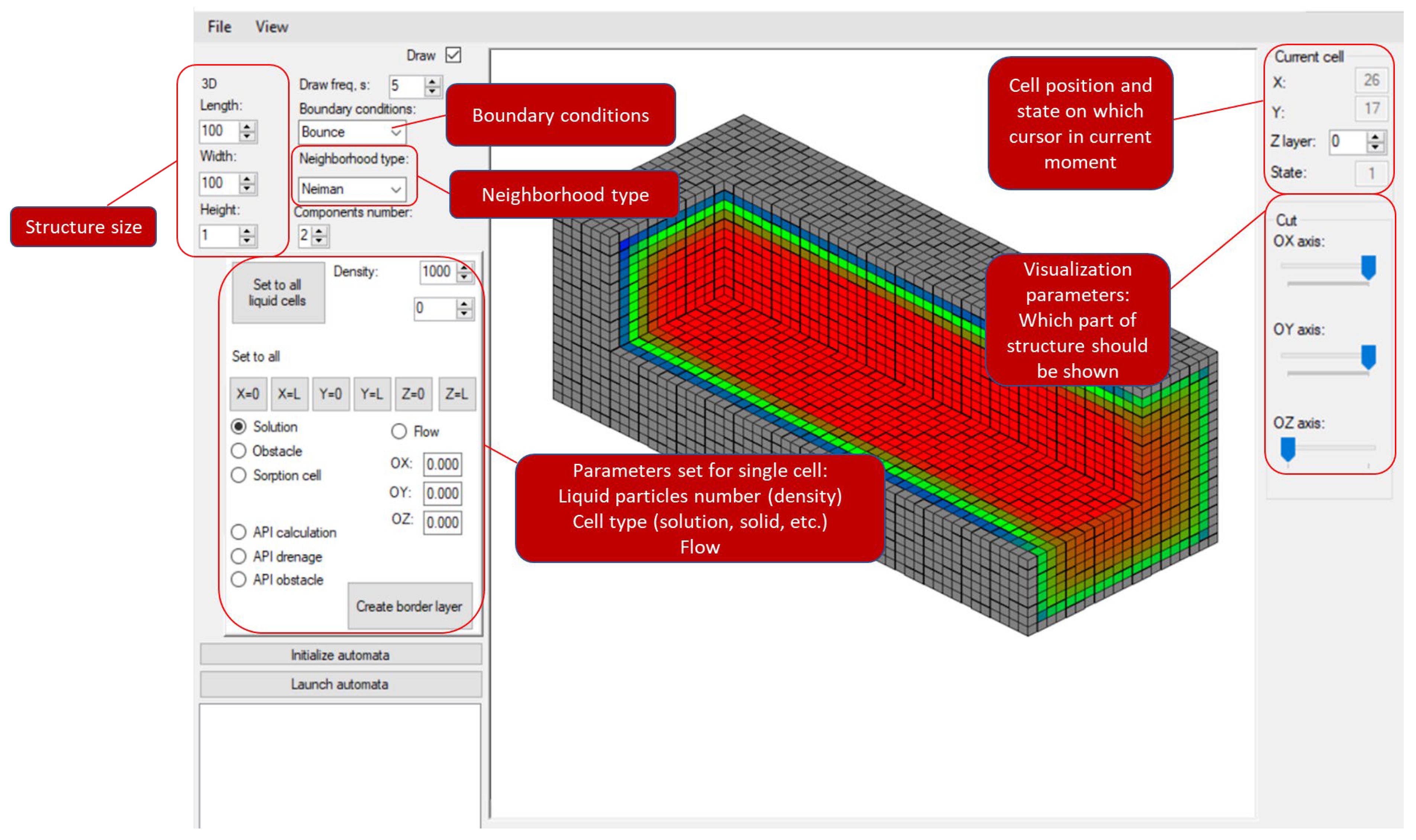
Figure 16 shows the interface window for hydrodynamics modeling with the LBM method.
The developed software module allows for multicomponent systems modeling. Also, the digital structures generated earlier can be used as input data (
Figure 17). This feature allows for modeling mass transport inside porous samples.
In the
Figure 17, the gradient from blue to red shows the relative strength of the flow from less to stronger, respectively. The grey cells represent solid area.
The module allows for interaction with the simulation field, creating arbitrary structures or changing existing ones, including directly during simulation (
Figure 18).
In the
Figure 18, the gradient from blue to red shows the relative strength of the flow from less to stronger, respectively. The grey cells represent solid area.
In addition, the LBM can be combined with CA models, forming a single complex model for different processes, which significantly expands its application areas. The developed software uses a hybrid model that combines the lattice Boltzmann method and the cellular automata approach, which allows for predicting the processes of active pharmaceutical ingredients (API) release from the aerogel particles and its flow in various media. Flow is simulated with the LBM, and the release process is simulated with a cellular automata model.
The main idea of the API release model is as follows. Each cell can have one of two states: aerogel particle and solution. Each aerogel particle cell has a given amount of API in it. Every time step, the aerogel cells near the solution cells release API in the solution cells. After that, API transportation in liquid media (solution cells) is calculated according to the LBM method (
Figure 19).
In the
Figure 19 the purple cell represents aerogel with API inside, the white cells represent solvent without API and the blue cells represent solution with released API.
This model was used in [
6] to model melatonin release from chitosan-based aerogel particles and showed high accuracy.
The advantage of this model is that it allows the user to obtain both the release curve and API concentration distribution at each time moment.
Another process that is calculated with the software complex is the API particles deposited on human tissues dissolution process. The dissolution process includes API dissolution and its diffusion in liquid media. For this process, two different CA models operate on cells field—the dissolution CA model and the diffusion CA model. This CA has three possible cell states: active pharmaceutical ingredient (API), solution and air (empty). Empty cells are added for cases when not all the particle area is in contact with a solution. The basic idea of the model is as follows: a deposited particle is placed on the field, which is a collection of cells with an active pharmaceutical ingredient (API) state.
After this, the system simulates the dissolution and mass transfer (diffusion) of the dissolved API. API state cells represent the elementary volume of the API in solid form, and solution cells represent cells containing solvent and dissolved API. Within the model, the dissolution process represents the transfer of the API mass from the API cell to the cell with the solution. The diffusion process in the model means that the API moves from a solution cell with more API to a solution cell with less API. After the API cell dissolves some amount of its API, it transfers to the solution cell. The calculation is carried out until there is not a single cell left with the API state—this means that all the API particles have passed into the dissolved state. For API particles that are not completely immersed in the solution, further calculations are made at each time step, when the immersed portion of the particle has dissolved and the particle is immersed further (
Figure 20).
In the
Figure 20 the yellow cells represent API particle, the grey cells represent air cells (where solution can’t flow) and the gradient from blue to red shows the relative amount of the API in cell from less to stronger, respectively.
Figure 20 shows that there is an air space where dissolution is not observed, so the particle interacts with solvent that is not all over its area. After the bottom areas, a completely dissoluted particle moves and other areas can interact with the media. Both the lattice Boltzmann method and the dissolution model can work in two- or three-dimensional space.
The developed software is implemented in C# on the .NET framework.
4. Results
In this work, a software complex to create digital models of porous materials was developed. The proposed software makes it possible to simulate the porous structures of aerogels using various models. The models are implemented with the possibility of a wide variation of input parameters, which allows for choosing a model for each type of aerogel, considering the features of the current sample, and for studying the dependence of the material’s different properties on its structure and calculating the properties of a material based on its digital structure, creating a digital model.
In addition, the developed software allows for modeling processes, for example, hydrodynamics inside digital porous structures using the lattice Boltzmann method and the CA particle dissolution model. The LBM can be combined with cellular automata models, which allows for the calculation of various processes inside porous structures, such as sorption, mass transfer processes and dissolution. Additionally, software modules can be expanded with new cellular automata and other discrete models.
With the suggested IAS, there were developed various aerogels of different types: silicon dioxide, silica–resorcinol–formaldehyde, polyamide, carbon, chitosan, cellulose and protein, and the following properties were predicted: thermal conductivity, electrical conductivity, mechanical properties, sorption and solubility. These models allow for establishing a connection between structure geometry and its properties, which further allows for the development of materials with required properties.
The IAS is a universal decision for studying and developing materials with required properties. It allows the use of cellular automata models (both original developments and independent implementation of existing models) with wide possibilities for varying their parameters and adding new modules, so it is a perspective tool for studying and developing new nanoporous materials. The developed software will reduce the required number of full-scale experiments by partially replacing them with computational ones, which will reduce time and costs for creating new materials with the required properties.


