1. Introduction
Virtual Reality [
1], Augmented Reality [
2] and Mixed Reality [
3] are three key concepts in modern computer graphics and engineering. The first technique involves the use of a helmet that isolates the user from the outside world bringing him in a fully simulated environment. The second one is developed for various devices including smartphones, tablets and special head mounted displays. It has been exploited in different sectors, such as design, entertainment, training, maintenance and cultural heritage. These two technologies stand at the opposite direction of an imaginary line, therefore Milgram [
4] introduced the concept of Virtual Continuum. In the middle point of the line stands the concept of Mixed Reality. This latter environment allows the interaction with virtual objects showing them in the real world. One of the most interesting uses of this technology is certainly the medical field [
5,
6], in which viewers can superimpose artificial projections (such as 3D CT scan) on the body of a patient. Thanks to Mixed Reality, surgeons can perform biopsies, laparoscopies or any other operation with greater precision. The research herein presented describes an application of Mixed Reality which has been deployed following a collaboration between Rizzoli Orthopedic Institute and the Department of Industrial Engineering at the University of Bologna in Italy. This study aims to the development of an innovative technique that allows to integrate, modify and cut objects in real time in order to develop an efficient application which can be used in medicine. Nowadays there are several CAD systems and scripts for 3D objects cut, but only a part of them can be used to split geometrical solids in real time and even a reduced number can be integrated into a Mixed Reality environment. Since the reference platform for the development of this applications is Unity [
7], a first search of tools for this environment was performed. Although cut algorithms such as MouseSlice, MeshCutting and Meshcut [
8] already exist, these packages show major limitations while trying to perform mesh slicing. In this paper an improvement of the last two scripts available in Github, under the “BLINDED_AM_ME” package [
9] is described. These allow to cut properly simple elements such as cubes, spheres and capsules, but when applied to complex geometries (bones in our case) they do not work properly. Furthermore, no remeshing mechanism is provided to simplify complex meshes and ensure slicing in reduced times. In the already available packages the cutting plane only affects the first object encountered, whereas it would be useful to allow the cut of several objects at the same time. In the original script available in internet, the part falls due to gravity once cut and it is destroyed. On the other hand, in our case study the surgeon must be able to manipulate all the fragments obtained after cutting operations. It is also useful to offer the user the possibility of setting the length of a virtual knife to cut all the objects in range. All these capabilities have been included in the environment described in this paper to improve what is available in the bibliography.
The paper is structured as follows: the next section describes the aim of the work and the methodology;
Section 3 reports a description of the software tools and hardware necessary to implement the methodology described in this paper;
Section 4 described the way in which raycast technique is used in this paper;
Section 5 introduces the cutting algorithms developed in this work;
Section 6 describes the quality error estimation carried out to compare the new technique with that already available;
Section 7 details the case study; the final section lists some conclusion and guidelines for the continuation of the research.
2. Motivation and Methods
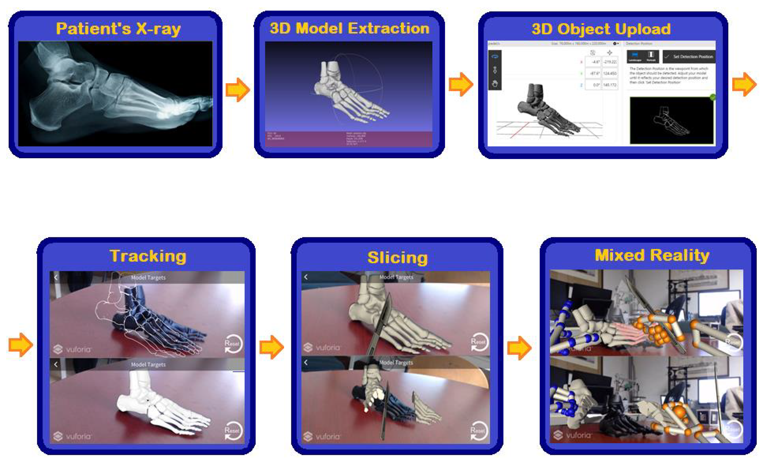
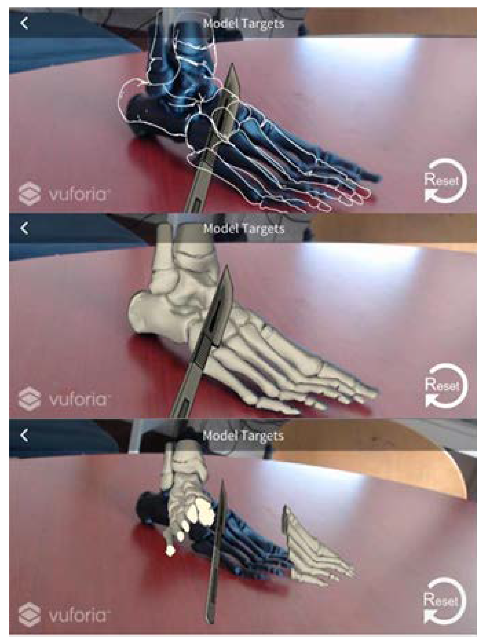
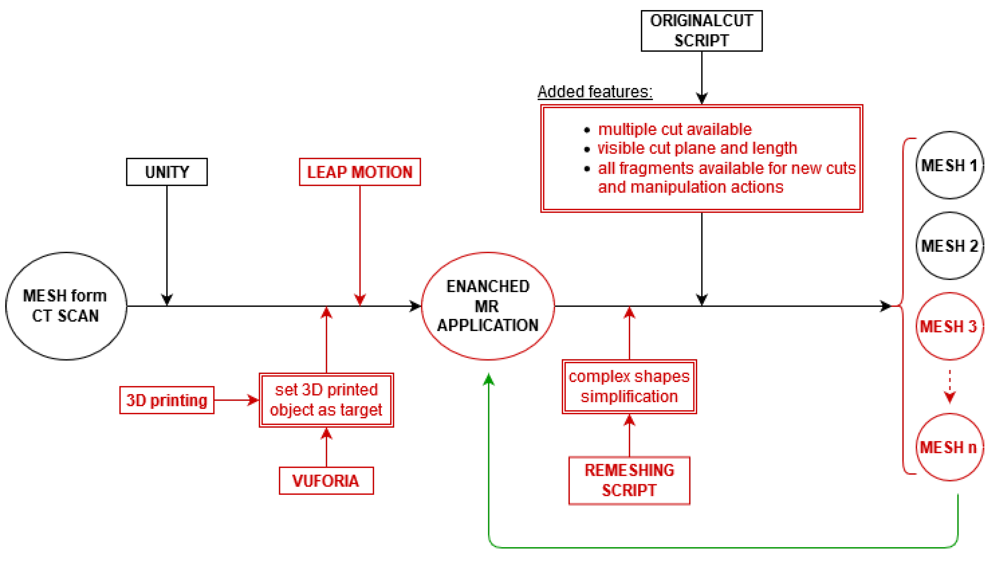
Figure 1 illustrates the main phases of the research. There are several ways [
10,
11] to extrapolate the 3D model from CT scan for pre-operative stage. 3D digital model can be obtained once available the radiographs provided by physicians operating in hospital divisions [
12].
Vuforia’s tools [
13], in particular “Vuforia model target generator”, is necessary to load the virtual object into the project and generate the corresponding Model Target. A framed photo of the 3D model is taken from the desired perspective and it will be used to perform the tracking. The latter process allows to associate the corresponding digital image to any physical element. A prototype of the 3D model is shown in
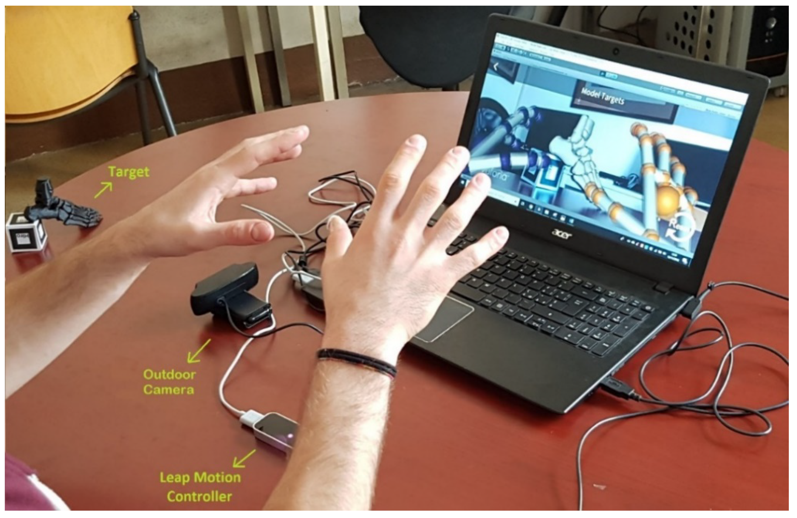
Figure 1 (second line, first frame from the left) where a nylon foot, made with the 3D printer MarkForged Mark Two, is tracked. At this point, the slicing algorithm is applied in order to cut the object in real time. LeapMotion [
14] is then integrated in the environment to create a Mixed Reality application useful to simulate surgical operations commanded by the moving of surgeon’s real hands. This technology allows the interaction with various virtual objects: picking, moving and cutting a digital model can be carried out using virtual scalpels without the need for a mouse or a keyboard, using hands instead.
3. Software and Hardware Tools for 3D Models in MR
The main tool used to create Mixed Reality applications is the Microsoft HoloLens viewer [
15]: it is a helmet equipped with transparent glasses which projects holograms of virtual objects allowing the user to view them superimposed to the real world and interacting with them. HoloLens is a fully-equipped device carrying several sensors and it has been already used for surgical purpose [
16]: However, sometimes HoloLens lacks in usability: it is a powerful tool, but it is not always easy to use. Leap Motion solves the problem: it is a device that return a real time 3D reconstruction of human hands. This specific feature is needed in a surgical application because of the need of tracking the human hands position. HoloLens can recognize simple hand gesture, but Leap Motion can detect in a precise way the movement of each finger in a specific area. This gives our methodology a higher accuracy respect to standard HoloLens solutions. The small movement detection provided by Leap Motion makes it possible the handling of a virtual knife, according to what presented below. The high fidelity of the two monochromatic IR cameras and three infrared LEDs are not enough to build up the scene that represents the digital twin of the original one. Vuforia is the software needed for this purpose. This platform is used for Model Target tracking technique which allows the recognition of a real object framed by the camera and associate it with its virtual twin. The Unity (2017.3.0f3) graphic engine allows importing the appropriate libraries to create Mixed Reality applications interfaceable with all the technologies previously described. MeshLab (v2016.12) [
17] and Blender (v2.81) [
18] are two software useful for 3D modelling: they are used in this application to manipulate and manage meshes of complex virtual shapes (where mesh means the polygonal lattice enclosing a virtual object) such as bones. Finally, it is worth describing the Invesalius3 free software that allows the reconstruction of virtual objects from medical scans provided by hospitals. Once the virtual object is built, the MarkForged Mark Two 3D printer [
19] has been used to print the prototypes to work on for the sake of this research.
4. Raycast in Computer Graphics
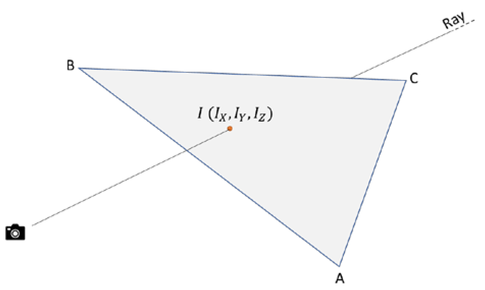
The mathematical framework developed for Ray cast [
20,
21] technique is needed to develop the software environment described in this paper. Ray cast is the most efficient way of find objects in front of a camera or in general in front of a specific point of view (
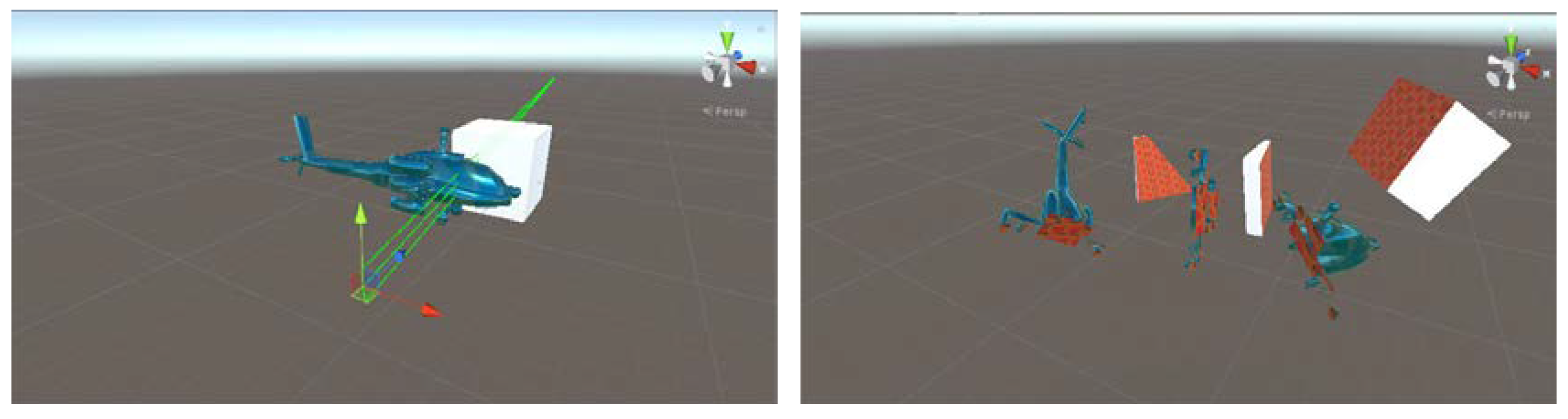
Figure 2). In our application, the evaluation of the interaction between the virtual knife and the virtual object is important and must be precise. After the precise projection of the knife plane on the object is computed, the cutting loop starts and the mesh subdivision takes place. To achieve this result, one camera pointing at the object (represented by the knife) and a target (the bone itself) is needed.
The geometry aspect is independent of the employed file format. In particular, obj files are used in this application because they are the preferred extension in Unity projects. Although structured meshes can be used for graphic applications, triangular meshes are the most common and the ones chosen for this paper. When the intersection point between the ray and the actual mesh is founded, the cut is performed through an original script developed for this research in order to divide the object in two parts. It is important noticing that the script and the raycast are faster on simplified meshes, so that a remeshing process is needed to increase the speed of the process. Another problem is represented by the fact that the cut must be performed for all the meshes in the direction of the knife because the target can be composed of several separated parts. Just to provide the reader with an example, in order to cut a forearm, two bones (radio and ulna) must be considered but it can happen that only one of them is to be cut. A control is implemented since it is important performing the right cut at the right place. The algorithm available in literature [
9] was meant to cut just the first object in the ray direction. This weakness is removed in the implementation proposed in this research, as better explained in the following sections. Summarizing in a few words, the raycast problem is solved many times excluding each time the object already cut in order to perform a clean mesh subdivision.
5. Cutting Algorithms in MR Environment
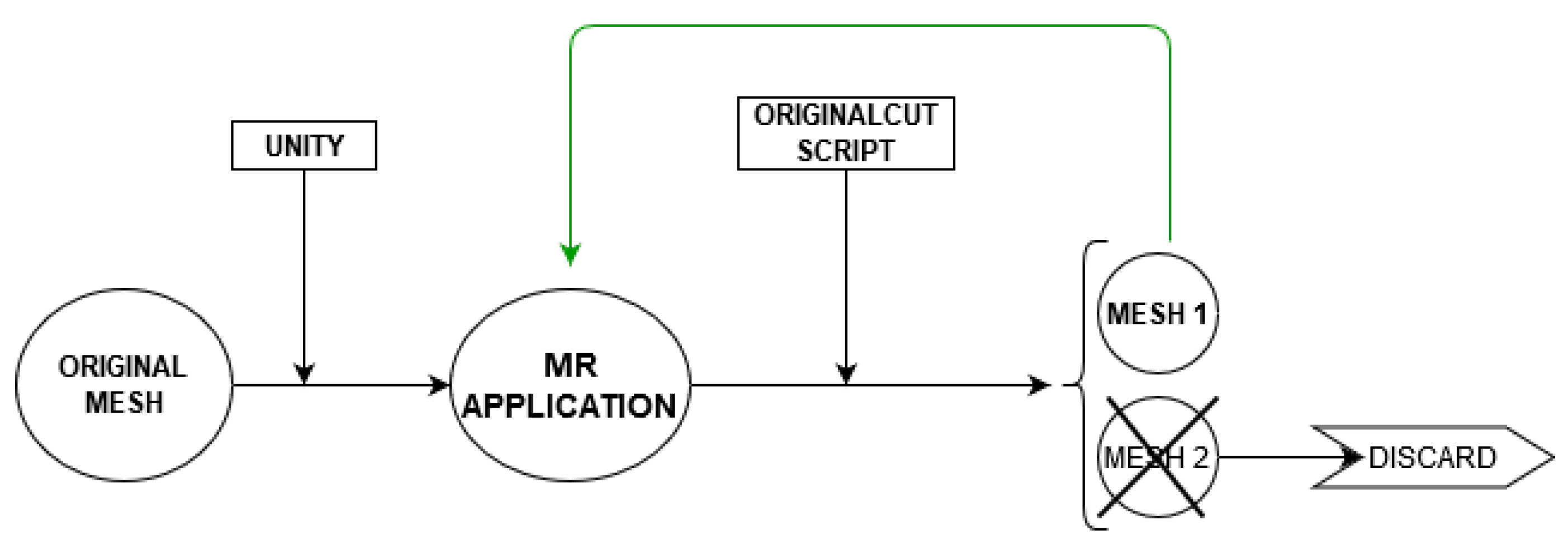
It is necessary to find a proper technique to dissect holograms in real time and then manipulate each obtained fragment to allow the interaction with three-dimensional objects projected with Microsoft HoloLens in a Mixed Reality environment. Nowadays, there are a lot of CAD systems and scripts developed to cutting operations of 3D objects. After an accurate research from bibliography, the BLINDED_AM_ME package was chosen and downloaded from Github. It contains several scripts to perform mesh slicing, but only two of them were considered useful for our aim: ExampleUseof_MeshCut.cs and MeshCut.cs have been analyzed and then modified in order to improve their usability in our application.
The first one, that involves the calling of the “Cut” function contained in the second script, essentially specifies how the obtained object falls due to gravity. The second one, instead, performs the actual cut (
Figure 3).
Although it was a good starting point, several changes had to be made on both scripts.
The main limitations of the original cutting algorithm are:
It is possible cutting only one object in the scene.
The cutting plane is not clearly visible and there is no possibility to choose its length in the object direction.
The removed fragment is destroyed.
It is impossible to manipulate the fragments obtained after cutting.
The multiple cut is not precise.
In more detail:
- (1)
The original script allows the cutting of a single object (by an invisible ray oriented towards the target) and if there are more elements one behind the other, only the first is cut. On the contrary, Surgeons might want to cut multiple objects together in the same scene. A first change is made by introducing in the script the “RaycastAll” method of the Physic class, which returns a vector of all “RaycastHit” affected by the cutting plane, as explained in the previous
Section 4.
- (2)
Under the current conditions, the cutting plane is an invisible ray of unknown length, hard to be used, especially considering that our goal is to create an interactive MR application. Thus, the user is provided with the possibility to handle a virtual scalpel (associated with the ray) and choose its length. In fact, a “bladeLength” variable which can be set by the user (of almost infinite length by default) is added to cut all the overlapping objects present in the scene.
- (3)
From the original algorithm the cut part of the victim object falls due to gravity effect and then it is removed. Clearly this is not the aim of this application, since surgeons must be able to handle both virtual fragments. The problem is solved removing the relative lines of code and modifying the script as explained at the following (bullet 4).
- (4)
Since the original software code was developed in such a way that the right-hand side cut of the part is destroyed, the resulted object is not enclosed in a suitable collider (BoxCollider, SphereCollider, CapsuleColider, etc.) because no other operations are performed on it. Instead, in this application, it is essential to allow the user to cut one or more objects in all the possible sub-parts that must remain active in the scene. In order to do this, the MeshCut.cs script has been modified to manage the right-hand fragment (which is now no longer disintegrated as before) after each cut, enclosing it in an appropriate collider in order to be manipulated.
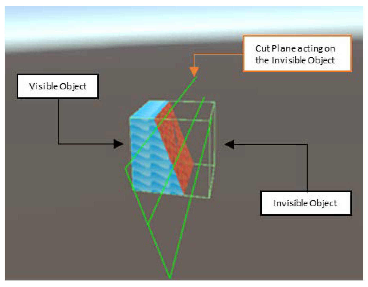
- (5)
Even the left-hand side (obtained after slicing the victim object) is not properly managed. In fact, if the knife moves slightly to the right after a first cut and tries to cut again (where there is nothing left), a “ghost cut” is enabled anyway (
Figure 4).
This happens because the collider is not resized after the slicing and it remains shaped as the initial object. The original script is modified in order to apply a MeshCollider that fits perfectly the generated shapes avoiding this annoying problem. Moreover, any type of pre-existing collider related to the “LeftSideObject” is destroyed and new MeshCollider is assigned. This procedure bypasses any possible collider conflict and overlapping.
The steps described in the bullets (1) to (5) can be summarized in Algorithm 1:
| Algorithm 1 MeshCut.cs |
1: if cut gesture detected do
2: count number of victim objects
3: for each victim do
4: cut object
5: create “LeftSideObj” and “RightSideObj”
6: delete current collider
7: create left and right-side colliders
8: return all cut objects
9: free memory |
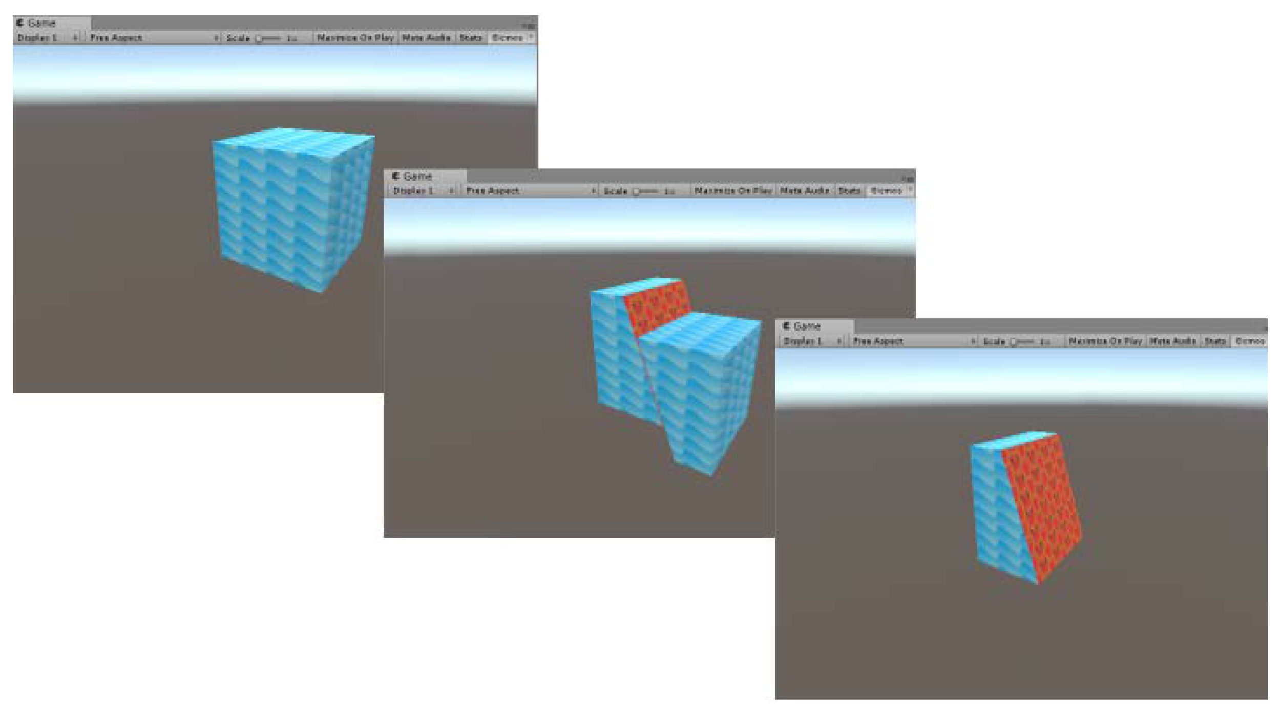
Once the appropriate changes to the script have been implemented, it is finally possible to make multiple cuts of several objects, guaranteeing the manipulation of the obtained fragments (
Figure 5).
A set of tests have been carried out on complex meshes to verify the efficiency of the script since the final aim of this research is to dissect even particularly articulated and geometrically complex bones. As expected, the more complex the meshes are, the longer the cutting time is. According to what already introduced in the text, a polygon reduction scheme has been developed to alleviate the computational time, which is presented in the following section. Based on the “remesh modifier” of the Blender software, a new script that operates a runtime mesh simplification is developed to reduce the time needed to process the geometrical model.
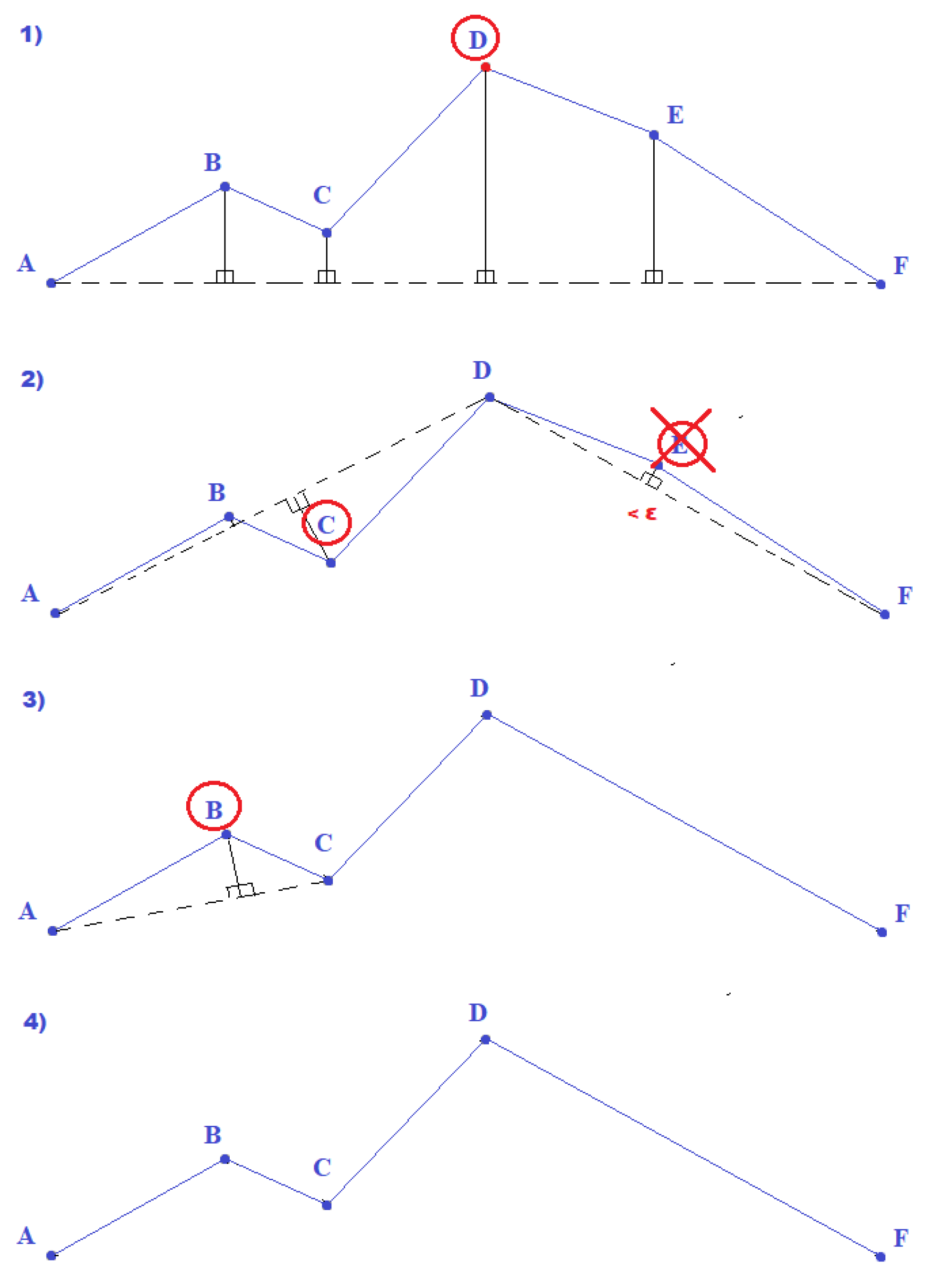
The Remeshing.cs script takes advantage of the Ramer–Douglas–Peucker (RDP) algorithm [
22,
23], which has been used to simplify the mesh.
A simplified curve consists in a subset of points of the original one and a factor ε defines the degree of approximation. It is possible to see a representation of the Douglas–Peucker algorithm for points sampling in
Figure 6.
RDP is basically a recursive algorithm applied to a set of points belonging to a curve.
The goal of this paper is to implement the algorithm in a real time application in order to upload or stream data directly from the CT scan reconstruction. A mesh consists of vertices stored as an array of “Vector3” (position in x,y,z coordinates) and connected by edges to form triangles. The RDP algorithm is applied to the set of vertices in order to build a new mesh starting from the filtered points. Moreover, this is done runtime, giving the user the possibility to select the maximum number of vertices that the object will be made of after the cut. The variable targetNumberOfVertices is introduced in the RDP Algorithm, repeatedly applying the computation with an increasingly small ε factor until obtaining a set of points with the specified dimension. The computation time clearly depends on the initial choice of the ε factor, the total number of vertices and the chosen dimension for the new set of points. Remeshing.cs script pseudo-code is shown in Algorithm 2.
| Algorithm 2 Remeshing.cs |
1: for all meshes do
2: create new mesh “SimplifiedMesh”
3: apply the mesh to the target object
4: input final number of vertices
5: for all vertices do
6: RDP algorithm
7: assign new vertices to “SimplifiedMesh”
8: recalculate mesh normal
9: show course meshes |
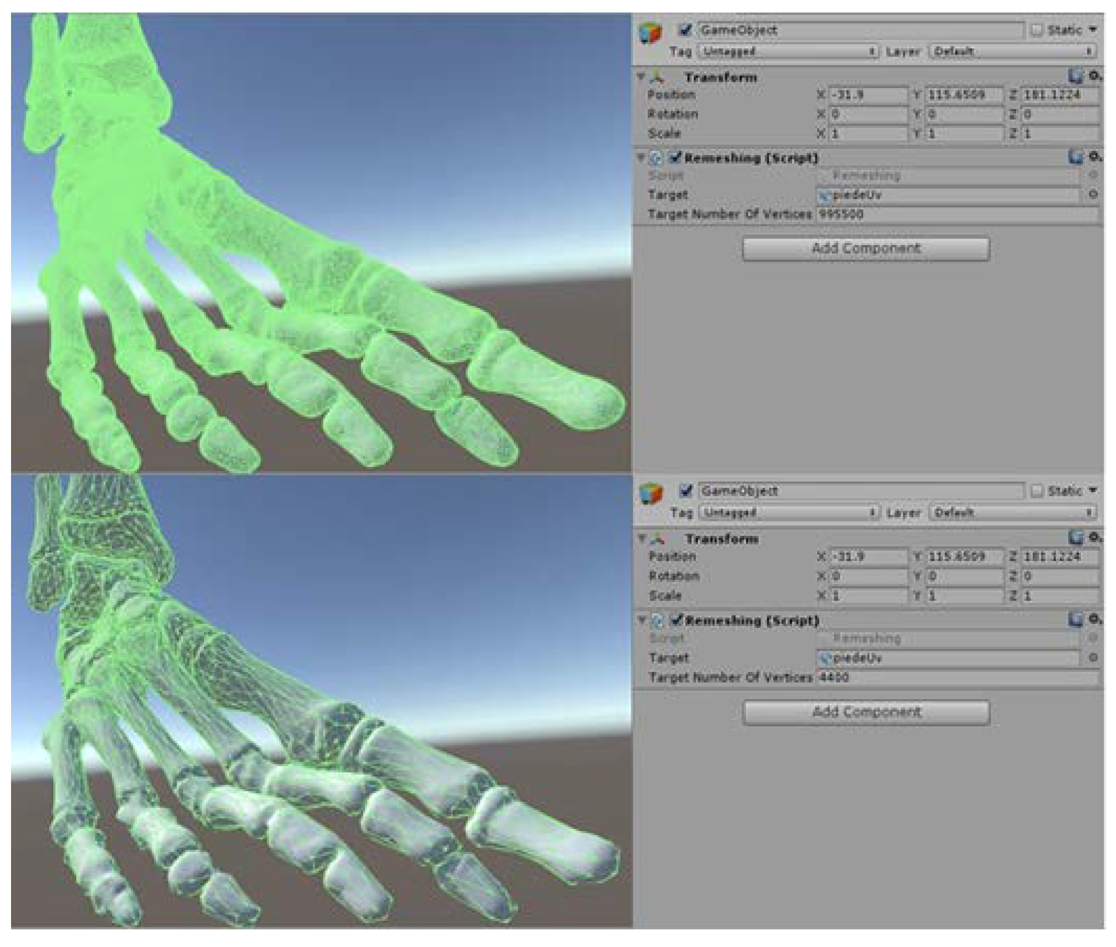
In this way, a real time mesh simplification is achieved for meshes of any complexity (
Figure 7).
6. Error Estimation
An error estimation analysis must be performed in order to validate the polygon reduction of the original mesh. The error is calculated using the Hausdorff Distance [
24]. This value represents the measure of distance between two meshes and it is evaluated as follows:
The two measures included in the equation above are not symmetric, and most of the Hausdorff filter computes only one of the two sides:
The results are the minimum, the maximum and the average distance between the target mesh (the one decimated) and the original mesh. The comparison is based on the diagonal of the bounding box, calculated with MeshLab (v2016.12), to avoid uncertainties derived from the model units.
Table 1 shows that in each case the maximum distance between meshes is less than 1/100 for an average face reduction of 99.3%.
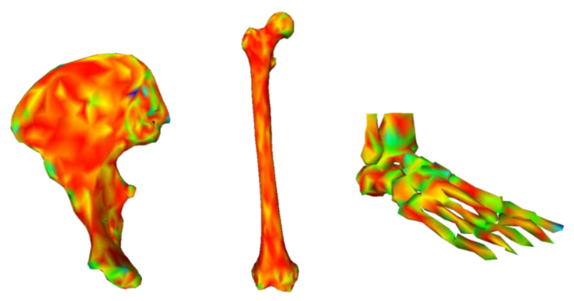
The same result can be visualized in
Figure 8 where the color scale is red-green-blue. Red means that the meshes are equals while blue is the higher error referred to the maximum model unit difference).
The only mesh that presents some green spot is the foot because of the complexity of the geometry itself. This can be seen in
Table 1 as well because the foot is the only mesh that has a mean distance higher respect to the other meshes but still this effect is well beyond the precision needed in our case study. The quality reduction is than negligible respect to the reduction in cutting time. This process shows that it is now possible to handle complex meshes derived from CT reconstruction without losing in quality, thus speeding up the entire algorithm. A typical CAD model from a CT scan can be made of up to millions of triangular faces.
Table 2 shows the time needed for a mesh cut before and after the decimation for a model with hundred thousands of faces.
The results are performed with Intel®Core™ i7-6500U 2.50 GHz 2.60 GHz processor, 8 GB Ram memory, Intel® HD Graphics 520 video card, Windows 10 × 64 bit operating system.
The time needed for a single cut is less than 2.5 s and the quality remains almost the same as the original object, so that the meshes can now be used in an Augmented Reality application. The tests about computational time has been carried out using a non-performing computer in order to simulate an operating scenario where a standard desktop PC is available.
7. Case Study
Once developed to mathematical and software tool necessary to carry out a virtual cut, a case study has been selected to test the environment developed and assess its efficiency and usability. A real CT of a foot bone has been processed to obtain a digital model. In the following, all the steps shown in
Figure 1 has been carried out to allow the capability of virtual cutting. At the end of the process, the foot virtual model, which is composed of several bones with complex shapes, has been successfully cut in a short time. The remainder of the section describes in detail how the environment previously described has been applied to this case study. In real applications, the tracking of 3D objects became the most important part of the methodology. Vuforia is the tool used for this purpose in the proposed case study. In particular, “Vuforia model target generator” is used to load 3D objects into the project and generate the corresponding Model Targets. As a result that the target is the model itself, the mesh extracted from CT scan through InVesalius3 is printed using a MarkForged Mark Two 3D printer. Once the tracking of the printed models with the related digital bones is finalized, only the scripts necessary for cutting and manipulating them are imported into the project. By carrying out several tests on the prototypes, we noticed that the tracking of more detailed and complex objects is more efficient than simple forms. Moreover, the camera takes more time to focus and recognize a reflective white element rather than a dark non-reflective one. Finally, we decided to associate a virtual scalpel with the cutting plane (
Figure 9).
Although HoloLens allows moving projected objects through the recognition of “gestures” into the environment, it is impossible to truly grasp the virtual bones and the scalpel, twirling it to make a precise cut.
For this reason, we decided to introduce into the application the Leap Motion, that allows to interact with various 3D objects, taking them, moving them and cutting them, without a mouse or a keyboard, but simply using the hands (
Figure 10).
At this stage, it is imported into the Unity project the Leap Motion Interaction Engine library, which allows tracking between the physical hands (positioned above the leap motion) and virtual hands. Several changes need to be done to the scripts and the whole application, to make it compatible with the new device. Above all, since the ability of use hands is achieved, it is necessary to choose a different input both by clicking the mouse and pressing a key on the keyboard to carry out the actual cut.
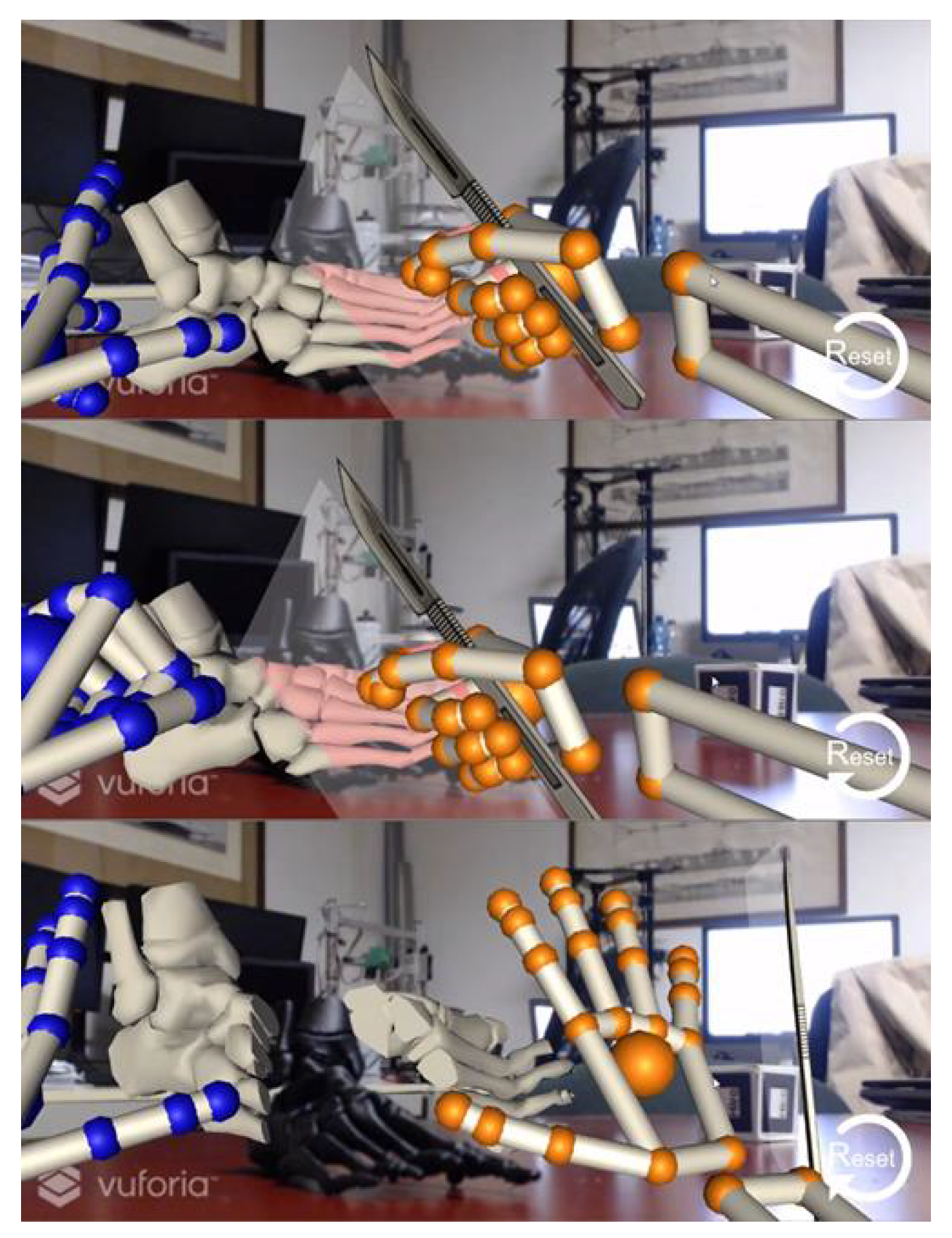
For this purpose, the previously mentioned library provides the ExtendedFingerDetector.cs script to associate a specific action with the position of every single finger. The “Gesture.cs” script is developed to associate the closing of one hand (chosen by the user) to the action of cut.
Figure 11 shows that each time the left hand is closed, the cut is enabled, and the knife is returned to its initial position (immediately close to the hands). This last feature has been added to have the knife always in the most suitable position.
The foot model used in this case study is composed of 350844 triangular faces. After the decimation described in the paper the mesh size has been reduced to 1925 faces, and the cut has been carried out in a time equal to 2.25 s.
8. Comments and Conclusions
This paper enriches the technique of virtual object cut in Mixed Reality application.
Figure 9 shows the perfect match between real and virtual object reached using Vuforia. With this tool it is possible to automatically scale models to the right dimensions and allow the real 3D printed bone to be the marker itself. This solution helps doctors, and generally non-experts in Mixed Reality, in using MR applications. The tracking and the fast cutting of the virtual object allows to simulate a surgical operation in the real world.
Figure 12 shows that the original approach available in literature was limited to just one possible cut without including any control on generated fragments and mesh quality.
To ensure an excellent experience with the application, various considerations and assessments are made on these parameters.
Figure 13 describes all the necessary changes carried out in this research, in particular: the algorithm manages multiple objects, it does not destroy generated fragments from previews cuts, and it sets all elements in the scene as interactive parts which can be manipulated in the further. Moreover, timing and quality are revisited making it possible a quasi-instantaneous cut without losing in shape quality. In this specific case, complex meshes are generated from CT scan, which are quite heavy due to the complexity of bone’s geometry.
After the reconstruction and simplification step, a re-adapting process implemented in the cutting algorithm is performed every cut to make available all fragments generated for new cuts. To achieve high performances, polygonal faces are reduced to 1925 in the case study herein presented.
There are still some limitations in the methodology herein developed. The material of the 3D printed object is the first one. Bones are well represented by white models, but light, shiny and texture-less objects are difficult to track, and complex algorithm are used to solve the problem following the typical approach described in literature [
25]. In this paper a model with dark matte material is used to avoid the problem limiting the realism of the experience of a real bone to the final user. The solution proposed to solve this problem is the implementation of multiple cameras to have a better look of the object from different points of view. Bones can be well tracked also because of their complex shapes that can give the tracking system points to monitor easy to detect and track. Moreover, the integration with the deep sensor of HoloLens will provide a higher precision and stability in positioning the 3D object. However, the introduction of more hardware devices implies higher acquisition and computational costs, while this application is designed to be portable and cheap. As a result of that, the HoloLens can be used as a high-tech visualizer because the implementation of Leap Motion makes this expensive product no more necessaire. Nevertheless, it is already planned to extend and integrate the application with Microsoft HoloLens viewer to expand the possibilities of the method. About possible application of the methodology introduced in this paper, the current system architecture is thought for medical problems, but interesting applications could be found in academic training, cultural heritage, maintenance or gaming industry. Just to provide the reader with an example, in education it would be possible to show to engineering students a section of a mechanical component overlapped to the original one: in this way, the drawing theory could be better understood without the need for expensive models.

 ,
, 


