
Constructal Optimizations of Liquid-Cooled Channels with Triangle or Square Sections in a Cylindrical Heating Body

1
College of Power Engineering, Naval University of Engineering, Wuhan 430033, China
2
School of Energy, Mechanical & Electronic Engineering, Hunan University of Humanities, Science and Technology, Loudi 417000, China
3
Institute of Thermal Science and Power Engineering, Wuhan Institute of Technology, Wuhan 430205, China
4
School of Mechanical & Electrical Engineering, Wuhan Institute of Technology, Wuhan 430205, China
*
Authors to whom correspondence should be addressed.
Mathematics 2023, 11(2), 357; https://0-doi-org.brum.beds.ac.uk/10.3390/math11020357
Submission received: 22 November 2022
/
Revised: 24 December 2022
/
Accepted: 2 January 2023
/
Published: 10 January 2023
(This article belongs to the Special Issue Recent Development and Application of Methods in Computational Mechanics)
Abstract
:Two new integrated models with heat source–heat sink are established, in which isothermal liquid cooling channels with triangle or square sections are, respectively, embedded in a cylindrical heating body with uniform heat production. Based on constructal theory, under the conditions of a fixed cylinder cross-sectional area and the proportion of channels, taking the dimensionless maximum temperature and the dimensionless entransy equivalent thermal resistance (EETR) as the optimization goals, the influences of distribution of liquid cooling channels on the heat dissipation capacity of integrated models are studied with the number and the center distance of liquid cooling channels as design variables, and the optimal constructs with different proportions of channels are obtained. The results show that when the proportion of channels, cross-sectional area and the number of liquid cooling channels are given, there is an optimal center distance to make the overall heat dissipation performance of the integrated model reach its best, but the optimal center distances for the two indicators are different. The dimensionless maximum temperature and the dimensionless EETR decrease when the proportion of channels increases, but the optimal dimensionless center distances are almost the same for different proportions of channels. The dimensionless maximum temperature with the triangular cross-section is lower than that with the square cross-section under the conditions of constant cross-sectional area and dimensionless center distance, which is the same as the case for the dimensionless EETR. The results can furnish the theoretical guidelines for the thermal design of cylindrical devices needing efficient cooling.
Keywords:
constructal design; entransy theory; electronics cooling; thermal design; evolution; generalized thermodynamic optimizationMSC:
80-101. Introduction
With advances in highly integrated electronic and electrical devices, the heat generation rate is increasing, and the heat dissipation problem has become a key bottleneck in these technological developments. In all solutions, using the liquid cooling method to cool the heating body is an important technical way to break through the heat dissipation bottleneck [1,2,3]. Senn and Poulikakos [4] proposed a water-cooled fin radiator made of silicon and applied it to super-large-scale integration. ABO Zahhad et al. [5] studied the influence of rib length ratio of long and short ribs on temperature and pressure drop loss in rectangular liquid cooling channels and obtained the optimal rib length ratio. Ahmed and Rageb [6] used numerical methods to study the heat dissipation performance of parallel and radial divergent liquid cooling channels. The results showed that the radial channel can improve the hydrodynamic and thermal performance of the radiator. Yang and Cao [7] studied the optimal design of a new type of liquid-cooled microchannel under four different parameters to achieve the target of making the total thermal resistance and pump power minimum.
Bejan [8,9] discovered the constructal law and proposed the constructal theory in studying the physical and deterministic mechanism of the formation of natural organization network structure, such as urban streets. The constructal theory [8,9,10,11,12,13,14] opens up a new direction for thermal design optimization. Bello Ochende and Meyer [15] optimized the constructs of two liquid-cooled microchannels, with the total heat transfer rate maximization as the objective under the given constraint conditions of the fixed total volume of the heat sink, the pressure drop and the volume of high-thermal-conductivity material. Xie et al. [16] optimized the constructs of line-to-line convective heat transfer tubes with the constraints of fixed channel surface area and channel total volume, aiming at minimizing the rate and amount of entropy production. Adewumi et al. [17] researched the heat transfer performance of a micro-pin fin composite microchannel heat sink via the numerical method and optimized the constructs of micro-pin fin. The integration of the liquid supply channel and the liquid return channel of the working fluid into the heat sink is more conducive to the compactness of the layout of electronic devices and becomes a new type of heat sink design. Farzaneh et al. [18,19] designed the constructs of square and equilateral triangle microchannel heat sink with working fluid reflux and microchannels. Aiming to make the maximum temperature difference minimization, Zhang et al. [20] implemented the constructal optimization of the arrow-shaped path comprising high-thermal-conductivity material in the square heat-generation body. You et al. [21] used a composite function, which is composed of hot-spot temperature and pump power as performance indicator, optimized the cooling channel diameter and body length-to-width ratio via the finite element method and obtained the optimal construct. Chen et al. [22] established a composite function that integrates the maximum temperature difference and pump work to optimize the three-dimensional disc of non-uniform heat production and obtained its thermal and hydrodynamic characteristics. Ahmadian-Elmi et al. [23] designed six heat sink models attached to the surface of high-temperature electronic devices and obtained optimal constructs. Bejan et al. [24] investigated the optimal constructs of a composite structure, considering both conduction and strength performance requirements. Constructal theory has distinct advantages in exploring the evolution law of the shape, structure, distribution and the performances for things and it is of outstanding scientific guiding value for exploring the optimal design of engineering structures with given constraints.
Based on the classical thermoelectric analogy method, the entransy concept and the entransy dissipation extremum principle (EDEP), which are a new physical quantity describing the heat transfer capacity of objects and a novel principle for optimizing the heat transfer processes with finite temperature difference, were put forward by Guo et al. [25]. These expanded the classical theory basis for the heat transfer subject. The EDEP can also be attributed to the minimum principle of entransy equivalent thermal resistance (EETR). Many scholars have shown enthusiastic interest and further enriched and developed the entransy theory. These lay a new advance impetus for heat transfer optimization [26,27,28,29,30,31,32,33,34]. Zhang et al. [27] analyzed the energy loss in an air-conditioning system using the entransy theory and obtained the relationship between entransy dissipation and system performance. Anwar et al. [29] defined the concept of the entransy effectiveness of a heat exchanger. In the studies of reversible thermal processes and thermal cycles, based on the entransy theory and variational theory, Cheng et al. [30] summarized and discussed the entransy function of steady-state heat transfer and derived the entransy function of steady convection heat transfer. Zhao et al. [31] optimized the heat transfer system by the EDEP and proposed a new optimization strategy that integrated local component optimization and global system optimization.
With the developments in constructal theory and entransy theory, Chen provided new insight into heat and mass transfer process optimization by combining the constructal theory and the entransy theory [10,26,35,36,37] and carried out a series of research in various aspects, such as the volume-point heat conduction, rib, cooling channel, heat exchanger, heat source and iron- and steel-production process.
In this study, two new heat source–heat sink-integrated models are further established, which are the cylindrical heating bodes with isothermal liquid cooling channels. The heat generation per volume in a solid is uniform, and the cooling channels are designed as triangle and square sections, respectively. According to the method combining the constructal theory and the entransy theory, given the cross-sectional area of the cylindrical heating body and the proportion of channels to cylindrical heating body (hereinafter referred to as proportion of channels) as the geometric constraints, the effect of channel evolution, i.e., channel shape, dimensionless circle distance and number of liquid cooling channels, on the dimensionless maximum temperature and the dimensionless EETR of the cylindrical heating body will be investigated based on the dimensionless method with different proportions of channels, seeking the optimal constructs. The results can provide theoretical guidelines for the thermal design of cylindrical devices with efficient cooling.
2. Mathematical and Physical Model
2.1. Geometric Model
The two types of heat source–heat sink-integrated models are shown in Figure 1.
The cylindrical solids generate heat uniformly and constancy, and the heat fluxes are . The outer edges of cylinders are adiabatic boundaries. The radius of the cylindrical cross-section is R and its area is SR, in which several liquid cooling channels are embedded. The cross-sections of the liquid cooling channels are triangular and square (Figure 1a,b, respectively). The side length of the triangle channel shown in Figure 1a is ltri, and the side length of the square channel shown in Figure 1b is lsqu. The cross-section area of each liquid cooling channel is Sr. The total cross-section area of all liquid cooling channels is SNr. The liquid cooling channels are uniformly distributed on the circumferences of concentric circles, and the distances between the centroid of each liquid cooling channel and the center of the cylindrical heating body are the center distances d.
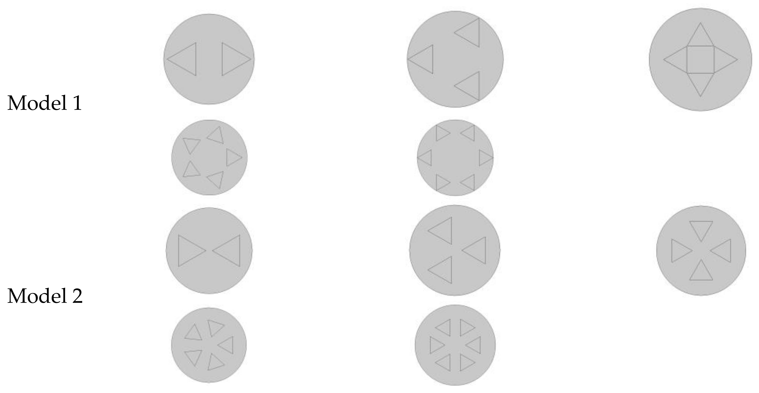
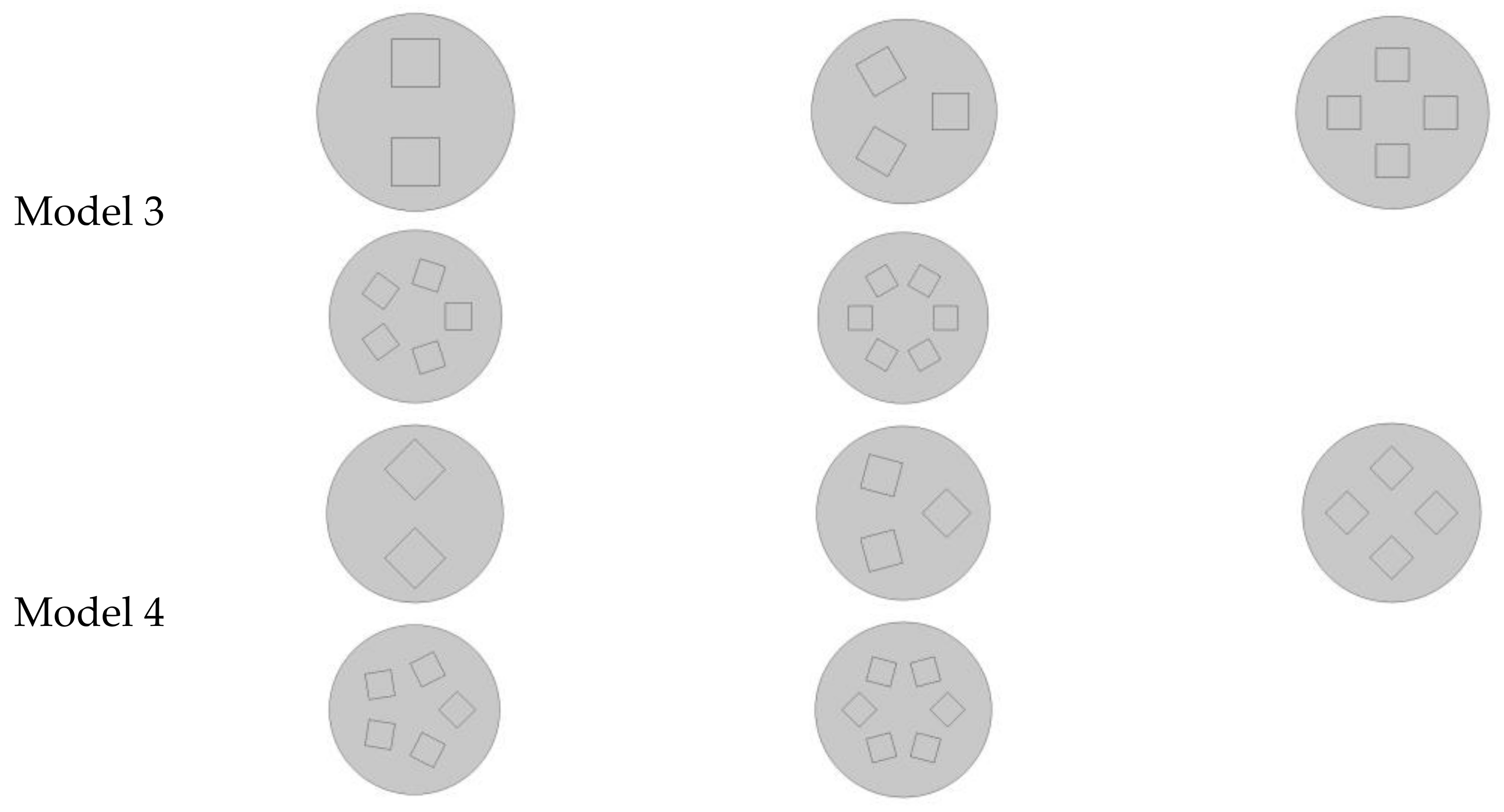
Figure 2 and Figure 3 show that the numbers N of liquid cooling channels of triangular section and square section range from 1 to 6, respectively. Models 1 and 2 are the cases of triangular cross-section with edge-to-edge and corner-to-corner distributions, respectively. Models 3 and 4 are the cases of square cross-section with edge-to-edge and corner-to-corner distributions, respectively. The number N of cooling channels is variable, but the total area SNr of channels remains unchanged as a geometric constraint in the optimization process:
It can be converted into the ratio of total channel area to cross-section area of cylindrical heating body, i.e., the proportion of channels:
In practical engineering applications, the too-large area of the cooling channel would limit the layout and operation of other components. Therefore, in order to balance the cooling effect and practical application value, this paper just selects 5%, 10% and 15% channel proportions to explore the impact of channel proportion on the cooling effect of the liquid cooling channel.
In the four models selected in this paper, the liquid cooling channel is radially symmetric with respect to the center of the cylindrical heater, which can make the cooling of the liquid cooling channel to the cylindrical heater more uniform, so that the cooling effect is better.
2.2. Heat Transfer Model
Heat-conducting solids are isotropic and the thermal conductivity k is constant. It is assumed that the fluid temperature in the cooling channels is . The heat is carried away by the coolant.
The two-dimensional heat-conduction equation in the circular section of the heating body is expressed as:
The boundary condition of the contact surface between liquid and solid is assumed as:
The adiabatic condition of the outer wall of the cylinder is expressed as:
The EETR of the cylinder is defined as:
where is the total entransy dissipation rate and is the function of entransy dissipation.
The entransy dissipation function is defined as:
The dimensionless quantities are defined as:
where is the dimensionless temperature and is the dimensionless center distance.
Substituting Formulae (8) and (9) into Formula (3), the dimensionless heat-conduction equation can be expressed as:
The dimensionless boundary condition of the contact surface between liquid and solid is:
The dimensionless adiabatic condition of the outer wall of the cylinder is expressed as:
The dimensionless EETR is expressed as:
3. Result Analyses
The dimensionless partial differential equation with its boundary conditions for heat transfer is solved by MATLAB. The one-time optimization with single freedom degree and double optimization with double freedom degree for liquid cooling channels with two cross-section shapes are studied all with the given cross-section area and heat flux of the cylindrical heating body, respectively.
3.1. One-Time Optimization with Single Freedom Degree
The one-time optimization with dimensionless center distance as a design variable is studied when the proportion of channels is 15% and the number of liquid cooling channels is three.
- (1)
- Minimization of dimensionless maximum temperature
Figure 4 and Table 1 show the relationship between the dimensionless maximum temperature and the dimensionless center distance of models 1, 2, 3 and 4. It can be seen from Figure 4 that when and , of each model changes from monotonically decreasing to monotonically increasing with the increase in and there are optimal dimensionless center distances being 0.33850 (model 1), 0.29337 (model 2), 0.31594 (model 3) and 0.31594 (model 4), respectively, which make the minimum values of 0.044637, 0.044436, 0.048623 and 0.047677. These show that in practical engineering applications, when the size, number and cross-section shape of liquid cooling channels are fixed, the hot-spot temperature can be reduced by selecting the appropriate channel distribution. When the cross-section shape changes, the cooling capacity of liquid cooling channels changes accordingly. The dimensionless maximum temperature of model 2 is lower than that of model 1 when the dimensionless center distance is small, but the opposite is true when the dimensionless center distance is large. This shows that for different distribution modes, different cross-section shapes of liquid cooling channels can be selected to achieve the best heat dissipation performance. For the triangle section, the edge-to-edge distribution is more suitable for application near the edge of the cylindrical heating body, while the corner-to-corner distribution is more suitable for the central region of the heating body.
- (2)
- Minimization of dimensionless EETR
Figure 5 and Table 2 show the influence of the dimensionless center distance on the dimensionless EETR for models 1, 2, 3 and 4. It can be seen from the graph that when and , of each model changes from monotonically decreasing to monotonically increasing with the increase in . Hence, there are optimal dimensionless center distances being 0.31594 (model 1), 0.30465 (model 2), 0.3103 (model 3) and 0.3103 (model 4), which make reach the minimum values of 0.018854, 0.018259, 0.02117 and 0.020935, respectively. It can be concluded that the best overall average heat dissipation effect can be obtained by optimizing the dimensionless center distance under the condition of constant proportion of channels, number and cross-section shape of liquid cooling channels, and the EETR reaches the minima. When the intersecting surface shapes of the liquid cooling channel are changed, the EETR also changes.
It can be seen from Figure 4 and Figure 5 that although the influences of on and are similar, and there are optimal dimensionless center distances to make the performance indicators reach the optima, but the optimal constructs corresponding to the two optimization objectives are different. The changes in cross-section shapes result in the changes in and , and the values of the triangular section are smaller than those of the square section. The first reason is that when the cross-sectional area is certain, the cross-sectional perimeter of the triangular section is longer and the contact area between the cooling liquid and the heating body is larger; the second reason is that the angle of the triangle is sharper than that of the square, that is, the angle is smaller. It has the ability to collect heat more deeply into the heating body like a fin, which makes the heat dissipation capacity of the liquid cooling channel stronger.
When the circular section liquid cooling channel reaches the position of the optimal dimensionless center distance, the dimensionless maximum temperature is 0.050233 and the dimensionless EETR is 0.022656. Therefore, it can be found that with the fixed proportion of channels, the dimensionless maximum temperature and dimensionless EETR of triangular section liquid cooling channels and square section liquid cooling channels presented in this paper are lower than those of circular section liquid cooling channels. The reason is that the corners of this polygon can penetrate into the heating body like fins and can cool the heating body better.
It can be seen from the above analysis that the dimensionless maximum temperature and dimensionless EETR of the four models decrease first and then increase with the increase in the dimensionless center distance, and there are minimum values, respectively. This rule is also applicable to heating elements of other cross-section shapes, but there are some differences in numerical values.
3.2. Double Optimization with Double Freedom Degree
- (1)
- Minimization of dimensionless maximum temperature
Given the conditions with the same proportions of channels, for different channel cross-section shapes (triangle section and square section), the double optimization with dimensionless center distance and number N (2, 3, 4, 5, 6) of liquid cooling channels as design variables is performed. The results are shown in Figure 6.
When and are constant, with the increase in of liquid cooling channel with different cross-section shapes, first decreases and then increases, and the minimum value can be obtained.
It can be obtained from Figure 6 that the dimensionless maximum temperature of the four models gradually decreases with the increase in the number N of liquid cooling channels when the proportion of channels is given. This is because when the number of liquid cooling channels increases, the distribution of the liquid cooling channels on the cross-section of the cylinder becomes more uniform. In fact, the heating solid area is discretized, which avoids the continuous concentration of heat production in the contiguous heating area and changes the distribution of thermal resistance, so that the heat can be dissipated through the liquid cooling channels in time, thus, reducing the dimensionless maximum temperature. Figure 6 shows that for different cross-sections of liquid cooling channels, the optimal dimensionless center distance first increases and then decreases with the addition of the number N of liquid cooling channels and reaches the maximum when N = 4. This indicates that the number of liquid cooling channels has an effect on the optimal dimensionless center distance, and the change in the number of liquid cooling channels will cause a change in the thermal resistance distribution of the model, which will lead to a change in the optimal dimensionless center distance. With the addition of the number N of liquid cooling channels, the of liquid cooling channels with different cross-sections tends to be the same. This is because when N is small, the cooling capacity of a single liquid cooling channel is stronger, so the cooling effect is greatly affected by the cross-sectional area of the channel and is different. When N is larger, the cooling capacity of a single liquid cooling channel decreases, and the influence of cross-section shape on the optimal distribution of the channel weakens, so is to be the same.
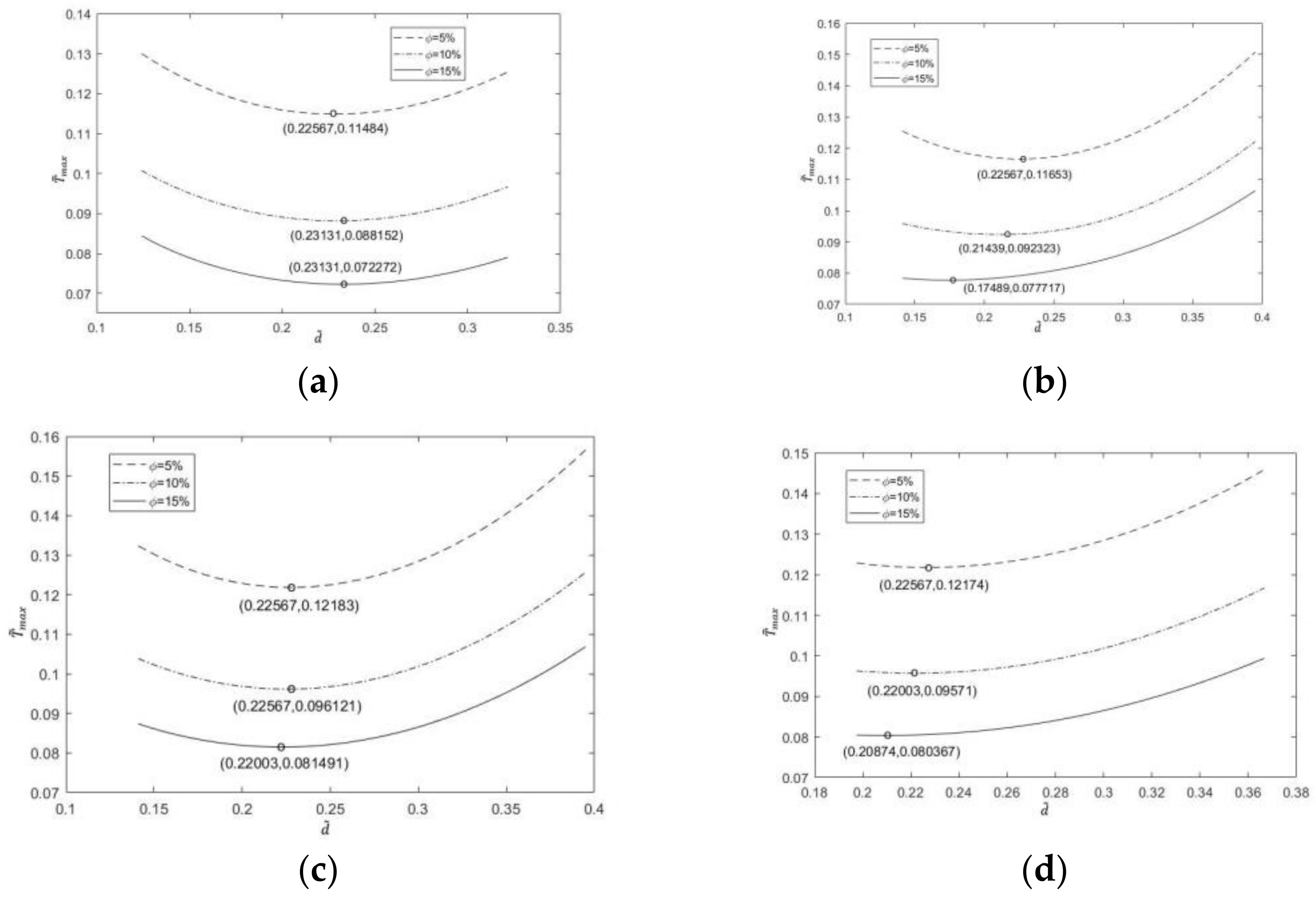
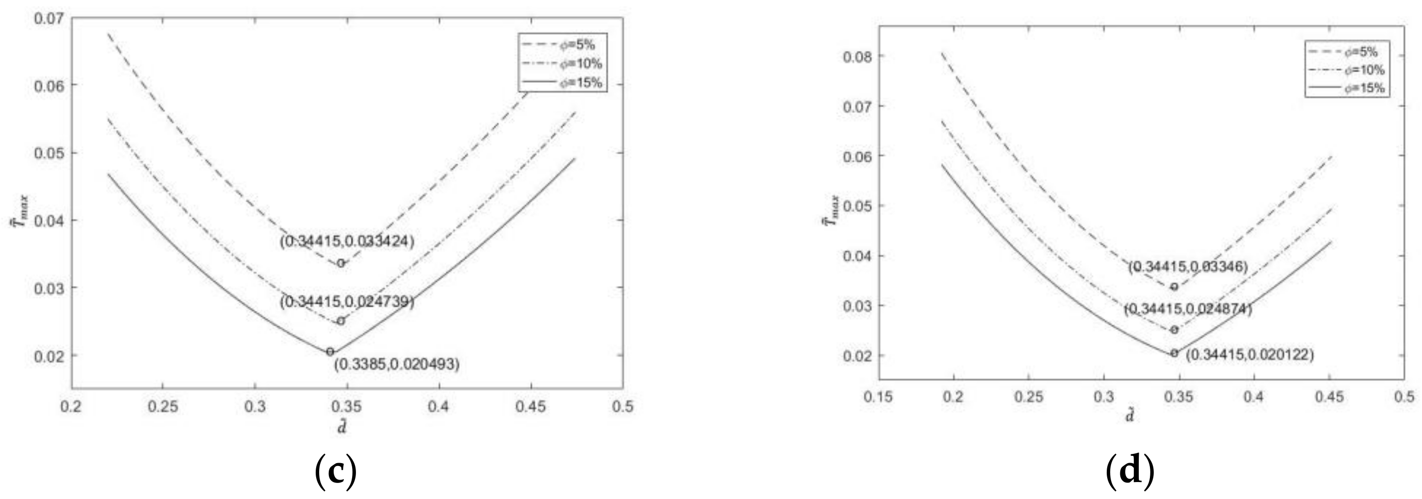
The proportion (5%, 10%, 15%) of channels is realized. Figure 7, Figure 8 and Figure 9 show the changes in with for different and . The optimization results show that for the liquid cooling channels with different cross-section shapes, when increases, corresponding to a different number of liquid cooling channels decreases further. With the increase in the proportion of channels, the total cross-sectional area of the liquid cooling channel increases, the cooling capacity increases, and the area of the heat-producing area decreases, which reduces the dimensionless maximum temperature. With the increase in , the optimal dimensionless center distance corresponding to a different number of liquid cooling channels is almost unchanged. This shows that the optimal dimensionless center distance is more susceptible to the number of liquid cooling channels. In all numerical examples, the optimal construct making the dimensionless maximum temperature minimum is model 2 when is 6, the proportion of channels is 15% and the dimensionless center distance is 0.34415. The minimum dimensionless maximum temperature is 0.016838.
Figure 10 shows the dimensionless temperature cloud chart of model 1 when = 3, = 15%, = 6, = 5% and = 6, = 15%.
It can be observed from Figure 10 that when and are constant, with the increase in , the high-temperature part of the temperature cloud chart moves from the edge part of the circular section to the center part and the region near the liquid cooling channels is always the lowest-temperature region; when it is the optimal dimensionless center distance, the temperature distribution of the heating body is more uniform. Under the same conditions with and , the temperature cloud chart of = 3 is larger than that of = 6, and the highest temperature is higher. When and are constant, the temperature distribution of the temperature cloud chart with = 15% is similar to that of the temperature cloud chart with = 5%, but the temperature is lower on the whole. The variation in the cloud chart with , and in models 2, 3 and 4 is similar to that in model 1, but the distribution and temperature are different.
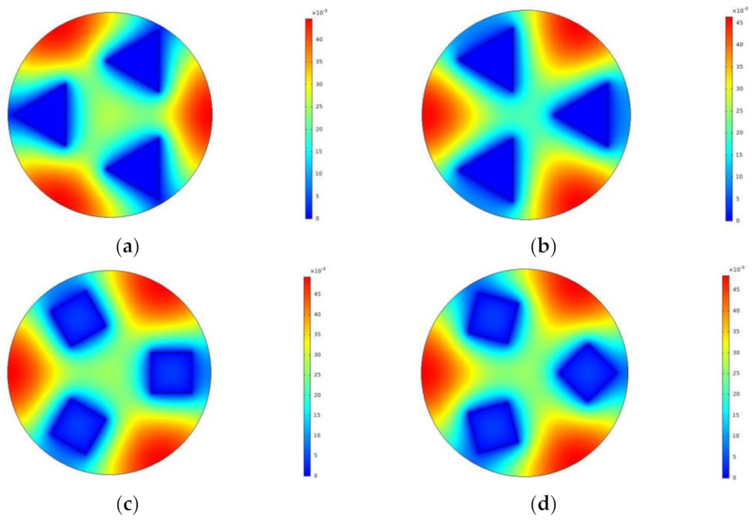
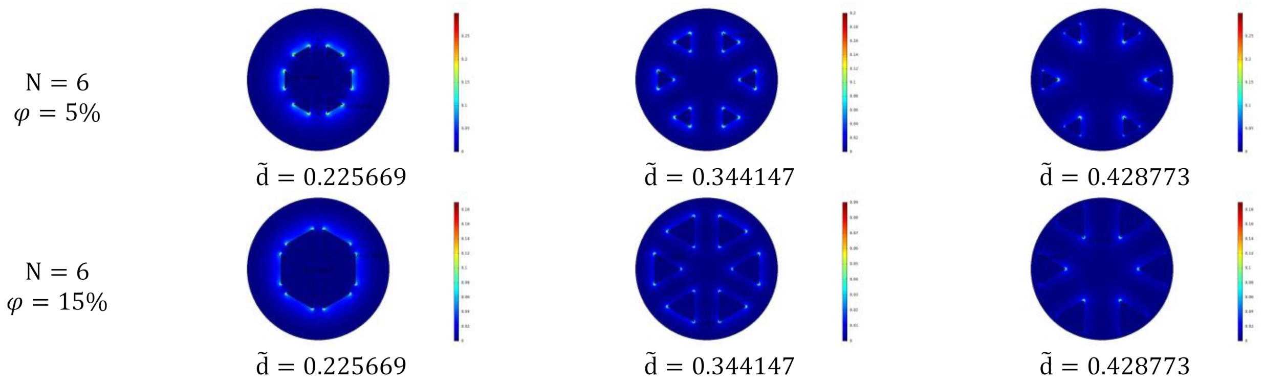
Figure 11 shows the temperature cloud chart of the liquid cooling channel models with different cross-section shapes at = 6, = 15% and = 0.344147.
From Figure 11, it can be seen that the changes in microchannel cross-section will change the temperature value and distribution of the heating body. Comparing Figure 11a,b, it can be found that the high-temperature area of model 1 is smaller than that of model 2 (that is, the red area), which means that the temperature of model 1 is lower. This can be verified in Figure 4. When = 0.344147, the dimensionless maximum temperature of model 2 is higher than that of model 1, i.e., the cooling capacity of model 1 is higher than that of model 2. It can also be seen from Figure 11 that the temperature of the high-temperature part of model 1 and 2 is lower, and that of model 3 and 4 is higher.
- (2)
- Minimization of dimensionless EETR
The influence of dimensionless center distance and the number of liquid cooling channels of four models on dimensionless EETR is depicted in Figure 12.
When the number of liquid cooling channels and the proportion of channels are constant, the dimensionless EETR of each model changes from monotonically decreasing to monotonically increasing with the increase in dimensionless center distance , and the minimum value can be obtained.
As shown in Figure 12, given the proportion of channels, the dimensionless EETR of the four models gradually decreases with the increase in the number of liquid cooling channels, and the optimal dimensionless center distance gradually increases with the increase in the number of liquid cooling channels. Moreover, with the increase in , the optimal dimensionless center distance of each model tends to be consistent, and the influence of the cross-section shape of the liquid cooling channel on becomes smaller and smaller.
The reason is that with the increase in the number of liquid cooling channels, the cross-sectional area of each liquid cooling channel decreases. Therefore, the influence of channel location on cooling capacity increases, but the influence of the cross-section shape of the liquid cooling channel decreases, so the optimal dimensionless center distance tends to be the same. In a word, when the number of liquid cooling channels is different, the optimal distribution of each cooling channel is different and the distance between channels is also different.
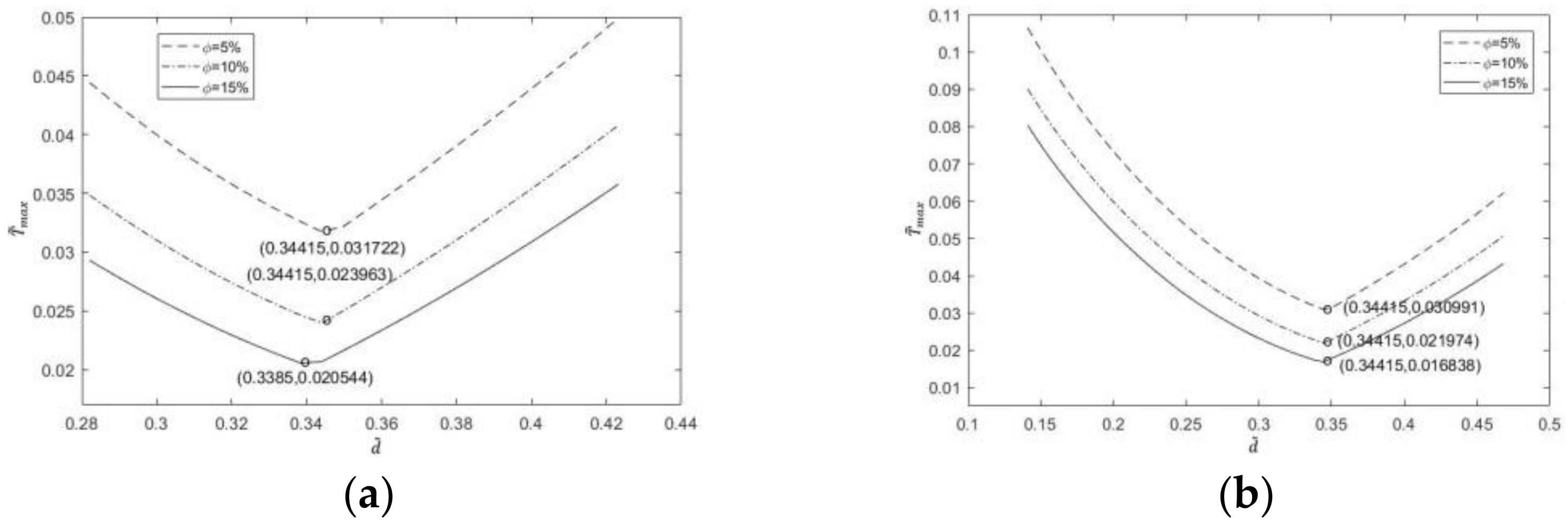
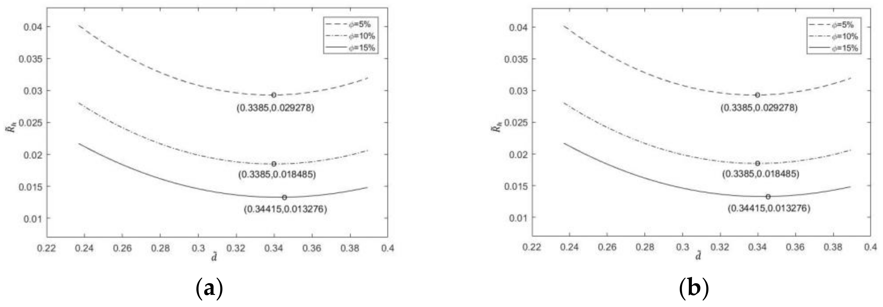
The proportion (5%, 10% and 15%) of channels is released. The optimization results in Figure 13, Figure 14 and Figure 15 show that corresponding to a different number of liquid cooling channels is further reduced when increases. Similar to the result of maximum temperature, with the increase in , the optimal dimensionless center distance corresponding to a different number of liquid cooling channels does not change, that is, the change in has no effect on .
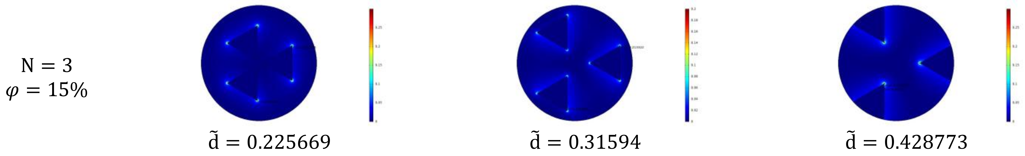
Figure 16 shows the entransy dissipation cloud chart of model 1 when , and . It can be seen from the figure that the region with high entransy dissipation rate is concentrated near the corner of the liquid cooling channels. When and are constant, with the increase in , the region of high entransy dissipation rate gradually moves from the circumferential side near the liquid cooling channel to the central side of the circular section of the heating body.
When and are constant, the larger is, the smaller the area of the region of high entransy dissipation rate near a single liquid cooling channel is. It can be said that the area of the high entransy dissipation rate part is divided and the total entransy dissipation rate is reduced. When and are constant, with the increase in , the perimeter of the cross-section of the liquid cooling channels becomes longer, and the distribution area of the region with high entransy dissipation rate is larger. Although the area is larger, the total entransy dissipation decreases, which leads to a decrease in entransy dissipation rate. Models 2, 3 and 4 are similar to model 1.
In all simulation cases, the optimal construct corresponding to the minimum dimensionless EETR is model 2 with the number of liquid cooling channels being 6, the proportion of channels being 15% and the dimensionless center distance being 0.36107, the minimum dimensionless EETR is 0.0078263.
Comparing the effects of dimensionless center distance, number of liquid cooling channels and proportion of channels on dimensionless maximum temperature and dimensionless EETR, it can be found that the influence characteristics is similar. In the range of = 2~6, when the number of liquid cooling channels increases, the optimal dimensionless center distance of dimensionless maximum temperature first increases and then decreases, while the optimal dimensionless center distance of dimensionless EETR gradually increases. Therefore, in practical engineering applications, there are different optimal cooling channel distributions for different heat transfer performance indicators.
Compared with the circular section liquid cooling channel model, the triangular section liquid cooling channel model and square section liquid cooling channel model proposed in this paper have smaller dimensionless maximum temperature and dimensionless EETR with a fixed proportion of channels and number of liquid cooling channels. Therefore, this paper provides two new alternative design schemes for practical applications.
4. Conclusions
In this paper, two new integrated models of heat source and heat sink with triangular and square cross-section liquid cooling channels embedded in a cylindrical heating body with uniform heat production are established. With the given constraints of cross-sectional area and proportion of channels in the heating body, the influence of dimensionless center distances and number of liquid cooling channels on the cross-section area of the heating body is studied by using the dimensionless method. The main conclusions are as follows:
- (1)
- Corresponding to different proportions of channels, channel section and number of liquid cooling channels, the dimensionless maximum temperature and the dimensionless EETR change from monotonically decreasing to monotonically increasing with the increase in the dimensionless center distance. There are different optimal center distances of the dimensionless circle, which make the dimensionless maximum temperature and the dimensionless EETR reach the respective minima.
- (2)
- The dimensionless maximum temperature and dimensionless EETR decrease with the increase in the number of liquid cooling channels. With the increase in the number of liquid cooling channels, the optimal dimensionless center distance of dimensionless maximum temperature first increases and then decreases, while the optimal dimensionless center distance of dimensionless EETR gradually increases.
- (3)
- The results reveal that the dimensionless maximum temperature and the dimensionless EETR decrease when the proportion of channels increases, but the optimal dimensionless center distances is almost the same for different proportions of channels.
- (4)
- For the same proportion of channels and number of liquid cooling channels, the dimensionless maximum temperature and dimensionless EETR of the triangle section liquid cooling channels are smaller than that of the square section liquid cooling channels, and with the increase in the number of liquid cooling channels, the cooling effect of model 2 (angle to angle in triangle section) is the best.
- (5)
- In engineering applications, the demands are multifaceted, including but not limited to the cost, the thermal stress, the convenience of manufacturing and operating and so on. Therefore, it is necessary to study the effects of cross-section shape of channels on the performances and far more performance indicators should be considered synthetically.
Author Contributions
Conceptualization, Y.L. and Z.X.; Methodology, Y.L., Z.X., D.L. and Z.L.; Software, Y.L., Z.L. and Y.G.; Validation, D.L., Z.L. and Y.G.; Investigation, Y.L.; Writing—original draft, Y.L.; Writing—review & editing, Z.X.; Supervision, Z.X.; Project administration, Z.X.; Funding acquisition, Z.X. All authors have read and agreed to the published version of the manuscript.
Funding
This research was funded by the National Natural Science Foundation of China grant numbers 51979278 and 51579244.
Institutional Review Board Statement
Not applicable.
Informed Consent Statement
Not applicable.
Data Availability Statement
Data will be made available on request.
Acknowledgments
The authors wish to thank the reviewers and editors for their careful, unbiased and constructive suggestions, which led to this revised manuscript.
Conflicts of Interest
The authors declare no conflict of interest.
References
- Van Erp, R.; Soleimanzadeh, R.; Nela, L.; Kampitsis, G.; Matioli, E. Co-Designing Electronics with Microfluidics for More Sustainable Cooling. Nature 2020, 585, 211–216. [Google Scholar] [CrossRef] [PubMed]
- Xiao, H.; Liu, Z.C.; Liu, W. Conjugate heat transfer enhancement in the mini-channel heat sink by realizing the optimized flow pattern. Appl. Therm. Eng. 2021, 182, 116131. [Google Scholar] [CrossRef]
- Zhang, G.H.; Sundén, B.; Xie, G.N. Combined experimental and numerical investigations on heat transfer augmentation in truncated ribbed channels designed by adopting fractal theory. Int. Commun. Heat Mass Transf. 2021, 121, 105080. [Google Scholar] [CrossRef]
- Senn, S.M.; Poulikakos, D. Laminar mixing, heat transfer and pressure drop in tree-like microchannel nets and their application for thermal management in polymer electrolyte fuel cells. J. Power Sources 2004, 130, 178–191. [Google Scholar] [CrossRef]
- Abo-Zahhad, E.M.; Ookawara, S.; Radwan, A.; Elkady, M.F.; El-Shazly, A.H. Optimization of stepwise varying width microchannel heat sink for high heat flux applications. Case Stud. Therm. Eng. 2020, 18, 100587. [Google Scholar] [CrossRef]
- Ahmed, S.S.; Rageb, A.M.A. Thermal performance study of parallel and radial divergence microchannel arrangement using numerical method. Basrah J. Eng. Sci. 2020, 20, 37–43. [Google Scholar] [CrossRef]
- Yang, M.; Cao, B.Y. Multi-objective optimization of a hybrid microchannel heat sink combining manifold concept with secondary channels. Appl. Therm. Eng. 2020, 181, 1155592. [Google Scholar] [CrossRef]
- Bejan, A. Street network theory of organization in nature. J. Adv. Transp. 1996, 30, 85–107. [Google Scholar] [CrossRef]
- Bejan, A. Constructal-theory network of conducting paths for cooling a heat generating volume. Int. J. Heat Mass Transf. 1997, 40, 799–816. [Google Scholar] [CrossRef]
- Chen, L.G. Progress in study on constructal theory and its applications. Sci. China Technol. Sci. 2012, 55, 802–820. [Google Scholar] [CrossRef]
- Chen, L.G.; Feng, H.J.; Xie, Z.H.; Sun, F. Progress of constructal theory in China over the past decade. Int. J. Heat Mass Transf. 2019, 130, 393–419. [Google Scholar] [CrossRef]
- Lorente, S.; Bejan, A. Current trends in constructal law and evolutionary design. Heat Transf. Asian Res. 2019, 48, 357–389. [Google Scholar] [CrossRef]
- Bejan, A.; Gucluer, S. Morphing the design to go with the times. Int. Commun. Heat Mass Transf. 2021, 120, 104837. [Google Scholar] [CrossRef]
- Bejan, A. Heat Transfer: Evolution, Design and Performance; John Wiley & Sons: New York, NY, USA, 2022. [Google Scholar]
- Bello-Ochende, T.; Meyer, J.P. Constructal cooling channels: Application to heat transfer in micro-channel heat sinks. Int. J. Emerg. Multidiscip. Fluid Sci. 2009, 1, 61–83. [Google Scholar] [CrossRef]
- Xie, Z.H.; Chen, L.G.; Sun, F.R. Constructal entropy generation rate minimization of line-to-line vascular networks with convective heat transfer. Int. J. Therm. Sci. 2013, 74, 72–80. [Google Scholar] [CrossRef]
- Adewumi, O.O.; Bello-Ochende, T.; Meyer, J.P. Numerical investigation into the thermal performance of single microchannels with varying axial length and different shapes of micro pin-fin inserts. Heat Transf. Eng. 2017, 38, 1157–1170. [Google Scholar] [CrossRef]
- Farzaneh, M.; Salimpour, M.R.; Tavakoli, M.R. Design of bifurcating microchannels with/without loops for cooling of square-shaped electronic components. Appl. Therm. Eng. 2016, 108, 581–595. [Google Scholar] [CrossRef]
- Farzaneh, M.; Tavakoli, M.R.; Salimpour, M.R. Effect of reverting channels on heat transfer performance of microchannels with different geometries. J. Appl. Fluid Mech. 2017, 10, 41–53. [Google Scholar] [CrossRef]
- Zhang, F.Y.; Feng, H.J.; Chen, L.G.; You, J.; Xie, Z. Constructal design of an arrow-shaped high thermal conductivity channel in a square heat generation body. Entropy 2020, 22, 475. [Google Scholar] [CrossRef]
- You, J.; Feng, H.J.; Chen, L.G.; Xie, Z.; Xia, S. Constructal design and experimental validation of a non-uniform heat generating body with rectangular cross-section and parallel circular cooling channels. Int. J. Heat Mass Transf. 2020, 148, 119028. [Google Scholar] [CrossRef]
- Chen, C.; You, J.; Feng, H.J.; Chen, L. A multi-objective study on the constructal design of non-uniform heat generating disc cooled by radial- and dendritic-pattern cooling channels. Sci. China Technol. Sci. 2021, 64, 729–744. [Google Scholar] [CrossRef]
- Ahmadian-Elmi, M.; Mohammadifar, M.; Rasouli, E.; Hajmohammadi, M. Optimal design and placement of heat sink elements attached on a cylindrical heat-generating body for maximum cooling performance. Thermochim. Acta 2021, 700, 178941. [Google Scholar] [CrossRef]
- Bejan, A.; Almahmoud, H.; Gucluer, S. Evolutionary design of composite structures for thermal conductance and strength. Int. Commun. Heat Mass Transf. 2021, 125, 105293. [Google Scholar] [CrossRef]
- Guo, Z.Y.; Zhu, H.Y.; Liang, X.G. Entransy—A physical quantity describing heat transfer ability. Int. J. Heat Mass Transf. 2007, 50, 2545–2556. [Google Scholar] [CrossRef]
- Chen, L.G. Progress in entransy theory and its applications. Chin. Sci. Bull. 2012, 57, 4404–4426. [Google Scholar] [CrossRef] [Green Version]
- Zhang, T.; Liu, X.H.; Tang, H.D.; Liu, J. Progress of entransy analysis on the air-conditioning system in buildings. Sci. China Technol. Sci. 2016, 59, 1463–1474. [Google Scholar] [CrossRef]
- Cheng, X.T.; Zhao, J.M.; Liang, X.G. Discussion on the extensions of the entransy theory. Sci. China Technol. Sci. 2017, 60, 363–373. [Google Scholar] [CrossRef]
- Anwar, M.K.; Sharqawy, M.H. Entransy effectiveness for analysis of heat exchangers. Glob. J. Res. Eng. 2017, 17, 49–52. [Google Scholar]
- Cheng, X.T.; Liang, X.G. Entransy functions for steady heat transfer. Sci. China Technol. Sci. 2019, 62, 1726–1734. [Google Scholar] [CrossRef]
- Zhao, T.; Liu, D.; Chen, Q. A collaborative optimization method for heat transfer systems based on the heat current method and entransy dissipation extremum principle. Appl. Therm. Eng. 2019, 146, 635–647. [Google Scholar] [CrossRef]
- Xu, S.Z.; Guo, Z.Y. Entransy transfer analysis methodology for energy conversion systems operating with thermodynamic cycles. Energy 2021, 224, 120189. [Google Scholar] [CrossRef]
- Geete, A.; Bhattacharjee, A.; Patwa, A.; Pandey, K. Entropy, exergy and entransy analyses on fabricated shell and spiral tube heat exchanger. J. Inst. Eng. India Ser. C 2021, 102, 897–908. [Google Scholar] [CrossRef]
- Xu, S.Z.; Zhao, T.; Chen, Q.; Liang, X.G.; Guo, Z.Y. State functions/quantities in thermodynamics and heat transfer. Fundam. Res. 2022, 2, 101–107. [Google Scholar] [CrossRef]
- Chen, L.G.; Feng, H.J.; Xie, Z.H. Generalized thermodynamic optimization for iron and steel production processes: A theoretical exploration and application cases. Entropy 2016, 18, 353. [Google Scholar] [CrossRef] [Green Version]
- Chen, L.G.; Xiao, Q.H.; Feng, H.J. Constructal optimizations for heat and mass transfers based on the entransy dissipation extremum principle, performed at the Naval University of Engineering; a review. Entropy 2018, 20, 74. [Google Scholar] [CrossRef] [Green Version]
- Wang, L.; Xie, Z.H.; Chen, L.G.; Wang, R.; Feng, H. Equivalent thermal resistance minimization for a circular disc heat sink with reverting microchannels based on constructal theory and entransy theory. Sci. China Technol. Sci. 2021, 64, 111–121. [Google Scholar] [CrossRef]
Figure 1.
The schematics of two circular sections. Wherein, subfigure (a) is a triangle section channel model, and subfigure (b) is a square section channel model. The red circle is to emphasize that the angle of the liquid cooling channel is a small arc connection to reduce the stress.
Figure 1.
The schematics of two circular sections. Wherein, subfigure (a) is a triangle section channel model, and subfigure (b) is a square section channel model. The red circle is to emphasize that the angle of the liquid cooling channel is a small arc connection to reduce the stress.

Figure 2.
The models 1 and 2 with N = 2~6.

Figure 3.
Models 3 and 4 with N = 2~6.

Figure 4.
The relationship between and of four models at = 15% and = 3.

Figure 5.
The relationship between and of four models at = 15% and = 3.

Figure 6.
The relationship among , and when = 15%. Where subfigures (a–e) are N = 2–6 respectively.


Figure 7.
The relationship between and in four models at = 2. Where subfigures (a–d) are Model 1, 2, 3 and 4 respectively.
Figure 7.
The relationship between and in four models at = 2. Where subfigures (a–d) are Model 1, 2, 3 and 4 respectively.

Figure 8.
The relationship between and in four models at = 4. Where subfigures (a–d) are Model 1, 2, 3 and 4 respectively.
Figure 8.
The relationship between and in four models at = 4. Where subfigures (a–d) are Model 1, 2, 3 and 4 respectively.

Figure 9.
The relationship between and in four models at = 6. Where subfigures (a–d) are Model 1, 2, 3 and 4 respectively.
Figure 9.
The relationship between and in four models at = 6. Where subfigures (a–d) are Model 1, 2, 3 and 4 respectively.


Figure 10.
A dimensionless temperature cloud chart of model 1.


Figure 11.
The dimensionless temperature cloud charts of four models when , and . Where subfigures (a–d) are Model 1, 2, 3 and 4 respectively.
Figure 11.
The dimensionless temperature cloud charts of four models when , and . Where subfigures (a–d) are Model 1, 2, 3 and 4 respectively.

Figure 12.
The influence of and on and when φ = 15%. Where subfigures (a–e) are N = 2–6 respectively.
Figure 12.
The influence of and on and when φ = 15%. Where subfigures (a–e) are N = 2–6 respectively.

Figure 13.
The influence of on in four models at = 2. Where subfigures (a–d) are Model 1, 2, 3 and 4 respectively.
Figure 13.
The influence of on in four models at = 2. Where subfigures (a–d) are Model 1, 2, 3 and 4 respectively.

Figure 14.
The influence of φ on in four models at N = 4. Where subfigures (a–d) are Model 1, 2, 3 and 4 respectively.
Figure 14.
The influence of φ on in four models at N = 4. Where subfigures (a–d) are Model 1, 2, 3 and 4 respectively.


Figure 15.
The influence of on in four models at = 6. Where subfigures (a–d) are Model 1, 2, 3 and 4 respectively.
Figure 15.
The influence of on in four models at = 6. Where subfigures (a–d) are Model 1, 2, 3 and 4 respectively.

Figure 16.
The entransy dissipation cloud chart of model 1.


Table 1.
The relationship between the minimum value of and in four models.
| Cross-Section Shape of Liquid Cooling Channel | Cross-Section Shape of Liquid Cooling Channel | ||||
|---|---|---|---|---|---|
| Edge to edge in triangle section | 0.044637 | 0.33850 | Angle to angle in triangle section | 0.044436 | 0.29337 |
| Edge to edge in Square section | 0.048623 | 0.31594 | Angle to angle in Square section | 0.047677 | 0.31594 |
Table 2.
The relationship between the minimum value of and in four models.
| Cross-Section Shape of Liquid Cooling Channel | Cross-Section Shape of Liquid Cooling Channel | ||||
|---|---|---|---|---|---|
| Edge to edge in triangle section | 0.018854 | 0.31594 | Angle to angle in triangle section | 0.018259 | 0.30465 |
| Edge to edge in Square section | 0.02117 | 0.3103 | Angle to angle in Square section | 0.020935 | 0.3103 |
Disclaimer/Publisher’s Note: The statements, opinions and data contained in all publications are solely those of the individual author(s) and contributor(s) and not of MDPI and/or the editor(s). MDPI and/or the editor(s) disclaim responsibility for any injury to people or property resulting from any ideas, methods, instructions or products referred to in the content. |
© 2023 by the authors. Licensee MDPI, Basel, Switzerland. This article is an open access article distributed under the terms and conditions of the Creative Commons Attribution (CC BY) license (https://creativecommons.org/licenses/by/4.0/).
Share and Cite
MDPI and ACS Style
Li, Y.; Xie, Z.; Lin, D.; Lu, Z.; Ge, Y. Constructal Optimizations of Liquid-Cooled Channels with Triangle or Square Sections in a Cylindrical Heating Body. Mathematics 2023, 11, 357. https://0-doi-org.brum.beds.ac.uk/10.3390/math11020357
AMA Style
Li Y, Xie Z, Lin D, Lu Z, Ge Y. Constructal Optimizations of Liquid-Cooled Channels with Triangle or Square Sections in a Cylindrical Heating Body. Mathematics. 2023; 11(2):357. https://0-doi-org.brum.beds.ac.uk/10.3390/math11020357
Chicago/Turabian StyleLi, Yunfeng, Zhihui Xie, Daoguang Lin, Zhuoqun Lu, and Yanlin Ge. 2023. "Constructal Optimizations of Liquid-Cooled Channels with Triangle or Square Sections in a Cylindrical Heating Body" Mathematics 11, no. 2: 357. https://0-doi-org.brum.beds.ac.uk/10.3390/math11020357
Note that from the first issue of 2016, this journal uses article numbers instead of page numbers. See further details here.