
Effect of Special-Shaped Nozzle Structure on Water Jet Performance
1
School of Mechanical Engineering, Yanshan University, Qinhuangdao 066004, China
2
School of Mechanical and Electrical Engineering, North China Institute of Aerospace Engineering, Langfang 065000, China
3
College of Mining Engineering, North China University of Science and Technology, Tangshan 063210, China
*
Author to whom correspondence should be addressed.
Processes 2022, 10(10), 2066; https://0-doi-org.brum.beds.ac.uk/10.3390/pr10102066
Submission received: 19 September 2022
/
Revised: 10 October 2022
/
Accepted: 11 October 2022
/
Published: 13 October 2022
(This article belongs to the Special Issue Intelligent Control and Maintenance of Fluid Component and System)
Abstract
:The impact force and effective impact area of are water jet are two important indexes for evaluating jet performance, and the outlet shape of the nozzle has a great influence on jet performance. In this study, five nozzles with different outlet shapes were designed, and water jet test experiments were conducted at different inlet pressures using an independently built water jet impact test platform, and the influence law of nozzle shape on the center impact pressure and flow coefficient of the water jet was investigated. The influence of nozzle shape on the effective impact area and entrainment rate of water jet was further investigated by numerical simulation. The results showed that the center impact pressure of the circular nozzle was the greatest when the inlet pressure and the target distance were small. The center impact pressure, the flow coefficient, and the effective area of the triangular nozzle with sharp edges were better than the traditional circular nozzle when the inlet pressure and the target distance were increased. Although the center impact pressure of the square nozzle is lower than that of the circular nozzle, its flow coefficient and effective impact area are higher than those of the circular nozzle with increasing target distance. The water jets of the elliptical and cross nozzles were the most divergent, and the jet performance was poor.
1. Introduction
Water is used in water jet technology as the working medium to produce high-speed jet beams by using specifically shaped nozzles with extremely high energy [1,2,3]. It is widely used in machining, coal mining, petroleum exploration, aerospace, medical surgery, equipment cleaning, and many other fields due to its clean, nonthermal effect, ease of control, high efficiency, safe and convenient operation, and other advantages [4,5,6]. As the core component of water jet technology, the structural parameters of the nozzle directly affect water jet performance. In recent years, scholars at home and abroad have conducted multifaceted research on the development of new nozzles to improve the performance of water jets by changing the inner channel structure and outlet shape of the nozzle [7,8,9].
To obtain water jets with high pressure and low divergence, Rouly et al. [10,11] designed an elliptical nozzle with variable long and short axis parameters. Three types of nozzles—namely, circular, elliptical, and rectangular—were used to transport the cutting fluid. The results showed that the circular nozzle had the best transport performance when the inlet pressure was high. Mohammad et al. [12] studied the attenuation law of the maximum velocity of water for circular, square, and rectangular nozzles with the same exit area using instantaneous visualization. The results showed that the velocity of the rectangular nozzle was about 21% higher than that of the other nozzles, and the jet converged faster when the target distance was small. Huang et al. [13] investigated the lateral deflection of peak pressure when an arc-bending jet impinges on plane, concave, convex, and inclined surfaces. The results showed that the lateral deflection of peak pressure was affected by the combination of jet velocity, surface shape, and surface angle. Weng et al. [14] designed circular grooves with different widths and numbers at the nozzle inlet. The liquid support effect produced by the circular grooves reduced the resistance between the water jet and the inner surface of the nozzle and improved the impact force of the water jet. Yang et al. [15] explored a square central body nozzle through numerical analysis. An optimal contraction was observed at the nozzle outlet, leading to strong cavitation in the jet and improving the cavitation jet performance. Song et al. [16] designed a petal-shaped nozzle, and the petal-shaped nozzle was able to achieve a 10.4% increase in average axial velocity compared to the traditional nozzle. He et al. [17] conducted erosion experiments on sand bricks using circular and square nozzles. The results showed that the erosion depth of the square nozzle was greater than that of the circular nozzle under certain conditions. Chen et al. [18,19,20] found that special-shaped nozzles had higher power and more uniform water droplet distribution in agricultural irrigation species by simulation and experiments. Some other scholars have studied the internal flow field of special-shaped nozzles on the basis of numerical simulations [21] and optimized the key structural parameters of the nozzles by using relevant optimization methods [22,23].
Previous research on new nozzles has mainly been focused on the velocity of the water jet and the flow field morphology. Few studies have investigated the influence of the nozzle shape and structural parameters on the impact pressure and impact area. This study explores the water jet performance of different nozzle shapes under different pressures and target distances on the basis of experiments and numerical simulation. It is concluded that the impact pressure and impact area of the triangular nozzle with sharp edges are better than those of the traditional circular nozzle at medium and high inlet pressures, and the axial attenuation of impact pressure is slow. The rest of the paper is organized as follows. In Section 2, the experimental equipment and method are introduced. In Section 3, the experimental data are analyzed to derive the effect of nozzle shape on the impact pressure and flow coefficient at the center of the water jet. In Section 4, a numerical model is developed to analyze the effect of nozzle shape on the effective impact area and entrainment rate of the water jet, and the comparison is verified in Section 3. In Section 5, the research results are summarized.
2. Experimental Equipment and Method
2.1. Experimental Equipment
An open water jet performance test system based on a polyvinylidene fluoride (PVDF) piezoelectric thin film sensor was independently built in this paper to investigate the effect of special-shaped nozzles on the performance of high-pressure water jets. The schematic of the experimental equipment is shown in Figure 1.
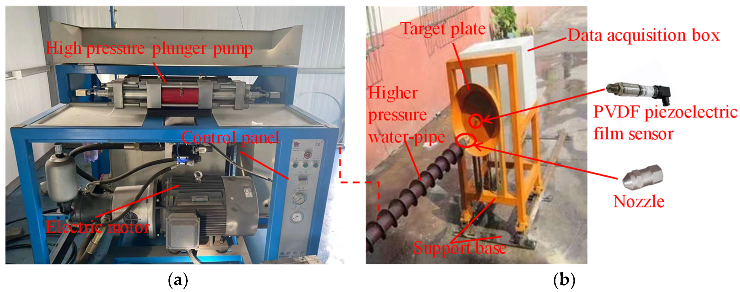
The whole system consists of two parts: the high-pressure water jet system and the performance experiment system. The high-pressure water jet system mainly consists of a high-pressure plunger pump, a check valve, a throttle valve, a pressure regulator valve, a pressure gauge, a flowmeter, a special-shaped nozzle, and a water collection tank. The high-pressure water jet is provided by the high-pressure plunger pump, and the pressure in the pipeline is controlled by the pressure regulator valve. The working condition parameters in the pipeline are monitored by the flowmeter and the pressure gauge. The special-shaped nozzle is connected to the high-pressure water pipe, and the water collection tank is placed between the nozzle and the target plate. Its size is 400 mm × 200 mm, which is much larger than the target distance and the diffusion distance of the water jet set in this experiment, thus ensuring the complete collection of the water jet. The performance test system mainly consists of the PVDF piezoelectric thin film sensor, the target plate, the data acquisition card, and the computer. The PVDF piezoelectric thin film sensor is fixed on the target plate, and its height is in line with the center of the special-shaped nozzle. The bottom of the target plate is fixed in the slideway on the experimental platform by bolts, and the target distance can be adjusted depending on the requirements of the experiment. The PVDF piezoelectric thin film sensor used was aPVF2.25-EK (Dynasen Company, Goleta, CA, USA), which is characterized by a compact structure, a high response frequency, and a wide measurement range. The experimental equipment is shown in Figure 2, and the main parameters of the whole experimental set up are present edin Table 1.
2.2. Experimental Method
During the experiment, the required working parameters were adjusted, the high-pressure plunger pump was started, and the water jet was ejected through the nozzle. The jet flow field stabilized after 10 s, and the data acquisition system was started. The system automatically recorded the collected data and processed them. The experimental data acquisition time was 30 s. The experimental data for the jet were collected three times in succession foreach nozzle under the same conditions, and the average value was taken to ensure the accuracy and precision of the measurement data.
In this experiment, the effect of the special-shaped nozzle on the performance of the water jet was studied. In accordance with previous research results, five nozzles, namely, circular, square, triangular, elliptical, and cross outlet shapes, were designed for this experiment. In addition to the outlet shape, the other structural parameters of the five types of nozzles were the same, and the outlet area of all nozzles remained the same, which is , in order to exclude the influence of other factors. The specific structural parameters are shown in Table 2, and the structural schematic of the nozzle is shown in Figure 3. A split design was adopted to facilitate processing due to the small inner diameter of the nozzle. The nozzle was divided into a contraction section and a straight outlet section, which were processed separately. The two parts were connected together by a metal seal ring and a nozzle sleeve following the completion of processing. The outlet shapes of the five nozzles are shown in Figure 4.
In the above table, the diameter of the circular nozzle is 2 mm, the side length of square nozzle is 1.77 mm, each side length of triangular nozzle is 2.69 mm, the long axis of elliptical nozzle is 4 mm, the short axis is 1 mm, and each side length of the cross nozzle is 0.79 mm.
3. Experimental Results and Analysis
3.1. Effect of Special-Shaped Nozzle on Water Jet Impact Pressure
Impact pressure is an important indicator for measuring the performance of water jets. After the water jet impacts the surface of an object, its speed decreases instantaneously. The momentum lost in this process is converted into a force that can break the object when acting upon its surface. The calculation formula for impact pressure P is as follows:
where is the density of the fluid, kg/m3, and is the fluid velocity, m/s.
As shown in Formula (1), the greater the impact pressure P, the better the effect of object fragmentation. Therefore, in this experiment, first, the effect of nozzles with different shapes on the impact pressure of water jet was measured. The total impact force F of the water jet was obtained after the data measured by the PVDF piezoelectric thin film sensor were processed by the data acquisition card and the computer, and the impact pressure was calculated as . However, inevitably, momentum and energy exchange between the fluid and the surrounding static gas occurs, and the water jet continues to diffuse after the water jet is ejected from the nozzle in accordance with the unsubmerged water jet structure [24]. This condition results in a continuous decrease in the water jet boundary velocity, thereby forming a gradient in the jet cross-section with a high central velocity and a low boundary velocity, as shown in Figure 5. This change in the velocity gradient leads to the uneven distribution of impact pressure on the jet cross-section, which cannot be calculated directly by using the formula .
In accordance with the research results presented in [25,26,27], the impact pressure Py at any point on the water jet cross-section can be expressed as follows:
In the above formula, Pc is the pressure at the center of the cross-section, MPa, y is the vertical distance between a point on the cross-section and the center of the water jet, mm, and Rx is the radius of the water jet on this cross-section, mm.
The pressure at any point on the cross-section can be obtained by changing Formula (2) as follows:
where , and . Therefore, the total impact force F on this section can be expressed as follows:
When y is extremely small, the higher-order term is omitted to obtain the following calculation formula for the central pressure:
In this experiment, the diameter of the sensor used is 0.25 mm, and the following formula can be calculated:
Substituting this result into Formula (3) yields . The calculation results show that the two results are extremely close, and with increasing target distance, the water jet continues to diffuse, and Rx becomes larger than the outlet size of the nozzle. Therefore, the collected experimental data can be used to calculate the central impact pressure of the water jet in accordance with Formula (5), and Formula (5) is applicable to all nozzles with a central symmetric shape, while Rx is the distance from the symmetric center to the edge point.
3.1.1. Axial Variation Characteristics of the Impact Pressure at the Center of the Water Jet
The axial change characteristic can reflect the change in water jet in advance, which is of great importance for studying the spatial dynamic change in water jet impact pressure [28]. The influence of different nozzle outlet shapes on the axial change of water jet impact pressure is shown in Figure 6. The inlet pressure of the nozzle stabilizes at 20 and 25 MPa through the pressure regulator valve, the axial target distance range is 40–200 mm, and the target distance interval of each measuring point is 20 mm. Each data point was collected in accordance with the method described in Section 2.2 in order to obtain the water jet impact force F of nozzles with different shapes, which was converted into the central impact force P using Formula (5). As shown in Figure 6, the water jet impact pressure shows a trend of attenuation with increasing axial target distance, which is in line with the law of water jet development. When the high-speed water jet is ejected into the static air, the water droplets constantly collide with air particles, resulting in a strong energy exchange. The air particles at the boundary of the water jet are constantly sucked into the water jet, forming a water/air mixture that moves forward together. With increasing target distance, the energy exchange between the water jet and the air increasingly accumulates, and the water jet velocity shows different degrees of attenuation. The water jet gradually diverges due to the inhalation of air particles. When the axial target distance is in the range of 40–140 mm, the impact pressure of the five shapes of nozzles decays rapidly in the axial direction with the increase in the target distance. This condition is mainly because the water jet is in the main section at this time, the turbulence of the two-phase flow field is intense, the energy exchange is frequent, the radial development of the jet is obvious, and its central impact pressure is affected by the target distance. The entrainment ability of the jet to the surrounding static air decreases after the axial target distance of 140 mm due to the decrease in the jet velocity. The energy exchange between water droplets and air particles reaches a relatively stable state, and the attenuation of the central impact pressure gradually tends to become gentle.
The attenuation of the axial impact pressure is compared in Figure 6a,b. The attenuation is more rapid when the inlet pressure , whereas the attenuation of the impact pressure tends to be gentle when the inlet pressure . This finding is because when the pressure is lower, the outlet velocity is relatively low, the water jet has poor clustering and is more likely to exchange momentum with the surrounding air, and the energy loss increases, causing the axial impact pressure to decay rapidly. When the inlet pressure of the nozzle is higher, the outlet velocity of the water jet is higher, and the water jet has better clustering. Only the water droplets at the water jet boundary collide with the air, resulting in energy exchange, which has minimal effect on the velocity at the water jet axis, so the impact pressure at the axial center decays slowly.
Compared with several different shapes of nozzles at the same inlet pressures and target distances, the impact pressure of the circular, square, and triangular nozzles is remarkably higher than that of the elliptical and cross nozzles. As shown in Figure 6a,b, the impact pressure at the center of the water jet of the circular nozzle is the highest within the target distance range of 40–140 mm. With increasing target distance, the center impact pressure of the triangular and square nozzles is slowly attenuated and starts to become higher than that of the circular nozzle. This condition shows that nozzles with sharp edges can still maintain good clustering with a large target distance, improving the performance of the water jet, which is consistent with the research results of previous authors [29,30,31,32].
3.1.2. Variation Characteristics of Center Impact Pressure with Inlet Pressure of the Special-Shaped Nozzle
The variation curve of the center impact pressure with the inlet pressure of different nozzle shapes at the same target distance was obtained in order to further analyze the influence of the nozzle inlet pressure on the jet impact pressure for different nozzle shapes, as shown in Figure 7 for a target distance range X of 80–180 mm, and an inlet pressure variation range of 10–35 MPa.
As shown in Figure 7, the impact pressure of the water jet shows an increasing trend with increasing inlet pressure. When the inlet pressure is lower than 25 MPa, the change in water jet impact pressure is relatively gentle, especially for the elliptical and cross nozzles, and is insensitive to changes in inlet pressure. When the inlet pressure exceeds 25 MPa, the center impact pressure of the different nozzles at the same target distance increases rapidly with increasing inlet pressure. This phenomenon shows that medium and high pressures are conducive to the nozzle maintaining jet convergence, thereby improving the impact pressure of the jet.
Several nozzle shapes were compared and analyzed at different inlet pressures. The water jet impact pressure of the triangular nozzle was the most sensitive to changes in inlet pressure. Within the selected target distance, the higher the inlet pressure, the faster the increase in the impact pressure of the water jet. When the inlet pressure P = 35 MPa, the water jet impact pressure obviously exceeds that of the other nozzles. This finding shows that when the inlet pressure is high, the water jet performance of the triangular nozzle is better. When the target distance is small, the water jet impact pressure of the circular nozzle is higher than the square nozzle with increasing inlet pressure. However, the advantage of the square nozzle becomes obvious at medium and high inlet pressures with increasing target distance, as shown in Figure 7e,f, and its impact pressure becomes higher than that of the circular nozzle, which is consistent with the conclusion drawn in Section 3.1.1. The water jet performance of the elliptical and cross nozzles was poor, especially when the inlet pressure P ≤ 25 MPa. Their impact pressures were remarkably lower than the other three shapes of the nozzle, and their impact pressures increased more slowly with increasing inlet pressure. When P > 25 MPa, their impact pressures increased with increasing inlet pressure, but they were still lower than those of the other three nozzles.
3.2. Effect of Special-Shaped Nozzle Structure on Water Jet Flow
Although the nozzle diameter is small, the energy carried by the water jet is large due to the high water pressure. Therefore, choosing a suitable nozzle structure is of great importance in using the energy of the water jet and reducing its energy consumption ratio in order to improve the performance of the water jet. According to Refs. [33,34], the calculation formula of water jet power is as follows:
where is the output power of the nozzle, W, the is density of fluid, kg/m3, is real flow, m3/s, and is outlet velocity, m/s.
The water jet power is mainly determined by the flow q and velocity v. The velocity is proportional to the impact pressure, as discussed in Section 3.1. Thus, this section focuses on the effect of the special-shaped nozzle on the actual water jet flow. The actual flow rate of the nozzle depends on its geometric shape, internal surface roughness, and internal flow state, and was mainly determined on the basis of the experiments. The calculation formula is as follows:
where is flow coefficient, dimensionless, and is theoretical flow, m3/s.
When the theoretical flow rate is the same, this coefficient represents the energy transmission efficiency of the nozzle. In this experiment, a high-pressure reciprocating piston pump is used, and its flow is proportional to the pressure, that is, when the inlet pressure is the same, its inlet flow is also the same. Thus, the flow coefficient of each nozzle must be investigated.
In this experiment, a simple and practical volumetric method was used to measure the flow, that is, the volumetric flow of each nozzle was determined by measuring the volume of fluid falling into the water collection tank per unit of time. The volume of fluid was measured using the measuring cylinder, and the time was recorded using a stopwatch. The inlet pressure of the nozzle was adjusted by the pressure regulator valve such that it would change within a range of 10–35 MPa, the inlet pressure was confirmed by the pressure gauge, and the theoretical flow was determined using the flowmeter. Each data point was measured three times, and the average value was taken. The specific data are shown in Table 3. The flow coefficient of the nozzle under different inlet pressures was calculated according to Formula (8). The actual flow of different shapes of the nozzle and their flow coefficients are shown in Figure 8.
As shown in Table 3 and Figure 8, the triangular nozzle had the highest flow rate, and the square nozzle and the circular nozzle exhibited minimal difference in flow rate at the same pressure. When the inlet pressure was low, the cross nozzle had the smallest flow rate. As shown in Figure 8a, the flow rates of several nozzles increased with increasing inlet pressure. The flow rate of the triangular nozzle increased the fastest, followed by the square and circular nozzles, and the flow rates of the elliptical and cross nozzles were the lowest. This findings show that the flow rate of the nozzles with sharp edges is more sensitive to changes in pressure, whereas the flow rate of the circular nozzle can more easily maintain stability.
Further analysis of Figure 8b shows that the relationship of the flow coefficient is . The flow coefficient of the triangular nozzle was 12.61% higher than that of the circular nozzle and 30.62% higher than that of the cross nozzle, which indicates that nozzles with sharp edges have a higher energy use rate for water jets. The flow coefficient of the triangular nozzle first increases and then decreases with increasing pressure, proving again that the flow rate of the triangular nozzle is sensitive to the pressure change, and an optimal inlet pressure does occur for this nozzle structure, at which point its flow rate reaches its maximum value. The flow coefficient of the square and circular nozzles changes slightly with pressure, the flow coefficient of elliptical and cross nozzles decreases slightly with increasing pressure, and the water jet energy use rate is low.
The actual flow rate of the nozzle depends on three main factors: the structural parameters of the nozzle, the internal surface roughness, and its internal flow state. In this experiment, the outlet shape of the five nozzles is different, but the structural parameters and processing methods are the same. Therefore, the outlet shape affects the local resistance coefficient of the nozzle, which influences its internal flow state, resulting in differences in the actual flow rate.
4. Numerical Simulation and Analysis
In addition to the impact pressure, the effective impact area is an important indicator of the water jet performance. Therefore, the impact of the special-shaped nozzles on the effective impact area was examined to more fully evaluate the advantages and disadvantages of special-shaped nozzles. In accordance with jet theory, the radial velocity on the jet cross-section gradually decreased from the central axis to the boundary in the main section of the jet, as shown in Figure 5 in Section 3.1, and accurately measuring the effective impact area of the jet cross-section by experimental means is difficult. Computational fluid dynamics (CFD) is widely used in the study of fluid flow due to its high accuracy, its ability to extract a variety of physical quantities, and its high efficiency [35,36]. In this study, CFD wasused to supplement the study of the jet performance of differently shaped nozzles.
4.1. Construction of Numerical Model
The numerical model of the nozzle was consistent with the nozzle size in Section 2.2, and the outlet flow field size was 60 mm × 60 mm × 220 mm in order to ensure the accuracy of the analysis results. Under these conditions, the influence of the flow field boundary on the calculation results can be avoided, while all of the experimental target distances in Section 2 can be included. In accordance with the experimental analysis, when strong momentum exchange occurs between the high-speed water jet and the air, the air at the boundary is sucked in by the water jet, and the droplets are “torn apart” by aerodynamic forces; the speeds of both are different, so the mixture model of multiphase flow model was selected to perform the numerical simulation, and the surface model type was sharp. The main phase was set to air, and the second phase was set to water; since water is an incompressible fluid, the transient and implicit pressure solver was used to perform the calculations. The gravity was set to 9.8 m/s2, and the direction was set perpendicular to the axis direction. Compared to the standard k–ε model, The RNG k–ε model is more suitable for dealing with complex flows with large flow curvature, and the model formula is as follows:
where k is turbulent kinetic energy, J, ε is turbulence dissipation tate, %, xi, xj are the x, y coordinates, Gk is the turbulent kinetic energy generation term, , are constants, , are the inverse effective Prandtl numbers of k and ε, and is turbulent viscosity, .
According to the control formula, the RNG k–ε model adds one item to the standard k–ε model, making the estimation of the vortex flow factor under turbulence more accurate. The nozzle has a small internal space and a complex shape, so the RNG k–ε model is more appropriate.
The nozzle inlet was set as the pressure inlet, the nozzle wall and the right end of the flow field were set as the wall, the wall function method was used in the near wall area, and other boundaries were set at the pressure outlet, the pressure value was1 atm, as shown in Figure 9. The inlet pressure value was the same as the above experimental pressure of 10–35 MPa. The volume fraction of water at the nozzle inlet was set to 1, the surface tension coefficient of water and air was set to 0.07, and the contact angle of water, air and wall was set to 70°. The volume fraction of water and the initial velocity of each medium in the initialization calculation domain were set to zero. The second-order upwind scheme is able to obtain higher accuracy than the first-order upwind scheme, so the SIMPLE pressure–velocity coupling algorithm and second-order upwind scheme were used to solve the control equation.
4.2. Model Meshing and Independence Verification
The number of grids has a certain impact on the accuracy and calculation time of a numerical simulation. However, for a given research problem, the further densification of grids does not affect the results but increases the calculation time once the density of grids has reached a certain level. This study used grid segmentation to divide the nozzle and flow field to ensure its accuracy and efficiency. The nozzles, with small structural dimensions and irregular shapes, were divided into an unstructured tetrahedral grid, the outlet flow field with regular shapes was divided into a structured hexahedral grid, and the key areas with complex flow were grid encrypted [37,38]. Taking the circular nozzle as an example, three density division methods are used for the numerical model to compare the impact pressure on the axis with the experimental results in Section 3.1.1 when the inlet pressure P = 20 MPa, as shown in Figure 10 and Table 4.
As shown in Figure 10, the axial distribution of the impact pressure of the circular nozzle at three different grid densities was consistent with the experiment results, and the data obtained under the second and third grid densities were extremely close. The overall error was controlled to within 6.5% following an increase in grid density, which meets the requirements of engineering practice. The reason for the gap between the numerical simulation data and experimental data is because the equipment is large, the experimental environment is outdoors, and a certain breeze can occur, which has a certain impact on the development of the water jet. A certain simplified processing method was used for the calculation of the experimental results, resulting in a deviation between the experimental and simulation results. Following a comprehensive consideration of the calculation accuracy and calculation time, the second grid density was selected for calculation. Under this grid density, when the inlet pressure is 20 MPa, the deviation between numerical simulation results and experimental results of the impact pressure on the axis of the other nozzles is shown in Table 5.
4.3. Resultsand Discussion
4.3.1. Effect of Special-Shaped Nozzle Structure on Water Jet Impact Area
The inlet pressure was P = 20 MPa. Contour maps of the water jet impact pressure of the five nozzles with different shapes at target distances of x = 40, 100, and 160 mm were generated, as shown in Figure 11. For comparison, all cross-sectional areas are 8 mm × 8 mm, and the impact force scale range is unified within the range 0–20 MPa, starting from the highest pressure of 20 MPa and extracting contours every 2 MPa until 2 MPa. The maximum impact pressure at the center of the jet decreases continuously for all nozzles with increasing target distance, which is consistent with the analysis provided in Section 3.1.1. The shape of the water jet near the outlet is the same as that of the nozzle. With increasing axial target distance, the shape of the jet gradually changes and develops into a circular boundary. This condition is the result of the continuous energy exchange between the water jet and air, and the air is constantly sucked into the water jet.
When the target distance is x = 40 mm, the center impact pressure of the circular nozzle is the greatest, and can reach more than 18 MPa, whereas the maximum pressure of other nozzles does not exceed 18 MPa, especially the elliptical and cross nozzles, where the maximum center impact pressure can be observed to belower than 16 MPa by comparing Figure 11a1–e1.The pressure decay was impacted within 20%, that is, P ≥ 16 MPa, when calculating the effective impact area. Stri > Ssqu > Scir, the effective area of the triangular nozzle was 1.86 times higher than that of the circular nozzle, and that of the square nozzle was 1.71 times higher than that of the circular nozzle. The pressure decay was impacted within 30%, that is, P ≥ 14 MPa, when calculating the effective impact surface. The effective impact area of the triangular nozzles wasstill the largest, at 1.88 times higher than that of the circular nozzle. The order was Stri > Ssqu > Scir > Sell > Scro.
When the target distance x = 100 mm, the maximum impact pressure of the circular and triangular nozzles was more than 14 MPa, and the effective impact area of the triangular nozzle was 1.61 times higher than that of the circular nozzle by comparing Figure 11a2–e2. The effective impact area was calculated to be P ≥ 12 MPa, and the order was Stri > Ssqu > Scir > Sell. The effective area of the triangular nozzle was 1.69 times higher than that of the circular nozzle, and the maximum impact pressure of the cross nozzle did not reach 12 MPa.
When the target distance x = 160 mm, the maximum impact pressure of the five nozzles decreased remarkably, as can be observed by comparing Figure 11a3–e3. The maximum impact pressure of circular, triangular, and square nozzles was more than 10 MPa, and the effective impact area of the triangular nozzle was still the largest, followed by the square nozzle, and the circular nozzle was the smallest, at P ≥ 10 MPa. The maximum impact pressure of the elliptical and cross nozzles decayed the most rapidly, only reaching 6 MPa.
With increasing target distance, the effective impact area of the triangular nozzle became the largest among the five nozzles. When the target distance x ≥ 100 mm, the impact pressure and effective impact area of the triangular nozzle exceeded that of the circular nozzle, showing better jet performance. When the target distance x = 160 mm, the impact pressure in the selected cross-sectional area was above 2 MPa, which is remarkably higher than the other four nozzles. Although the maximum impact pressure of the square nozzle was lower than that of the circular nozzle, its effective area was higher than that of the circular nozzle. When the target distance x = 160 mm, its maximum impact pressure was equivalent to that of the circular nozzle, which fully demonstrates that nozzles with sharp edges have better ability to entrain the surrounding fluid and the water jet performance is superior, especially when the target distance is high. However, the water jet impact pressure and the effective impact area of the elliptical and cross nozzles were poor. The specific effective areas of the five nozzles under different target distances are shown in Table 6.
In accordance with the research method described above, the effective area of the impact pressure decay within 50% was calculated for the five nozzles in the cross-section of the target distance x = 100 mm at inlet pressures of 10, 15, 20, 25, 30, and 35 MPa, as shown in Figure 12. With increasing inlet pressure, the effective impact area of the triangular and square nozzles increase drapidly, showing good jet expansion ability. The effective impact area of the elliptical and cross nozzles were minimally different, and exhibited an exponentially increasing trend in the high-pressure stage. The increase rate of the effective impact area of the circular nozzle shows a relatively stable linear law as a whole, indicating that its jet has good bunching property and is insensitive to pressure changes.
4.3.2. Effect of Special-Shaped Nozzle Structure on Jet Entrainment Rate
Most of the energy is transferred to the surrounding fluid, and the velocity of the jet body decreases because of the attenuation of the axial velocity of the jet. However, increasing the surrounding fluid results in turbulence moving forward with the jet body under the entrainment of the longitudinal vortex, so that the jet flow gradually increases along the way, and then the effective jet area expands. Therefore, the jet entrainment rate of the nozzle is a fundamental factor affecting jet performance.
The entrainment rate was calculated by using the formula proposed by Zhang et al. [39]:
where c is fluid entrainment rate, dimensionless, m0 is mass flow of fluid outlet, kg/s, m is the mass flow rate of the fluid in the cross-section at a target distance x, kg/s.
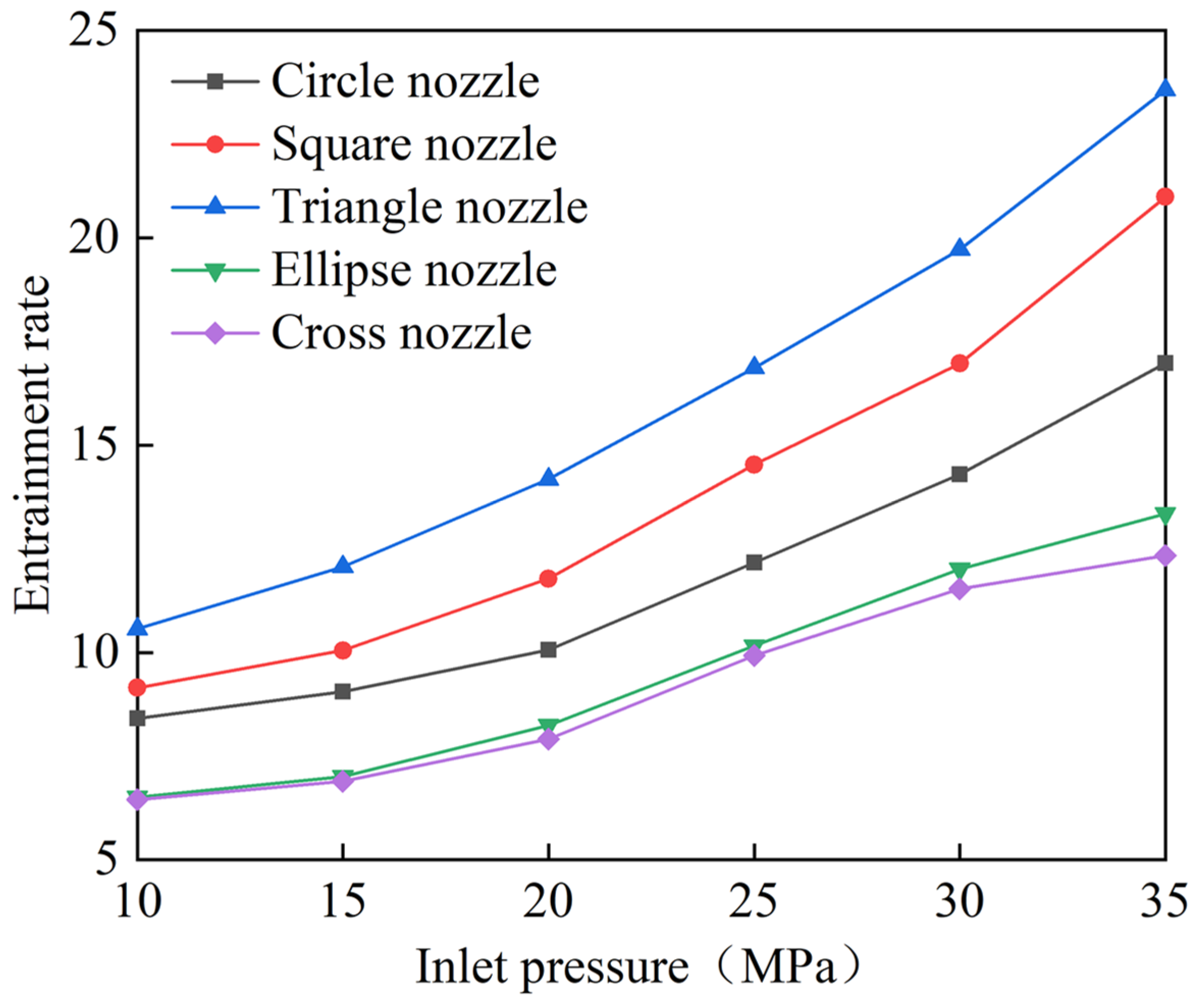
The larger the value of c, the stronger its ability to entrain the surrounding fluid. The entrainment rate of the five nozzles at a target distance x = 100 mm was calculated at inlet pressures of 10, 15, 20, 25, 30, and 35 MPa, as shown in Figure 13.
The entrainment rates of the five nozzles increased with increasing pressure, and the rates of increase of jet entrainment rates were different at different inlet pressures. At an inlet pressure of P ≥ 25MPa, the rate of increase of the entrainment rate of the jet was remarkably higher than that at medium and low pressures (P < 25MPa). This finding is because the outlet velocity of the jet increased rapidly in the medium- and high-pressure stages, and the entrainment ability of the jet to the surrounding fluid was enhanced. The entrainment rate of the triangular nozzle wasthe highest, and its jet entrainment rate was 1.24–1.50 times higher than that of the circular nozzle and 1.67–1.87 times higher than that of the cross nozzle. This finding is because the triangular nozzle had a longer cross-sectional perimeter, thus increasing its contact with the surrounding fluid, and thereby increasing its entrainment capacity. The change law of the jet entrainment rate of the five nozzles at different inlet pressures is consistent with the change law of effective area in the previous section, which proves again that the entrainment capacity of jet is an important factor affecting the expansion of their effective impact area.
5. Conclusions
In this study, the water jet performance of circular, square, triangular, elliptical, and cross nozzles was investigated by performing experiments and numerical simulation. The variation laws of water jet axial center impact pressure attenuation, water jet flow coefficient, water jet effective impact area, and water jet entrainment rate under different inlet pressures were analyzed. The main conclusions are as follows:
(1) When the inlet pressure P < 25 MPa and the target distance x < 140 mm, the circular nozzle has the best jet bunching performance, highest central impact pressure, and slowest axial attenuation, followed by the triangular, square, and elliptical nozzles. The water jet of the cross nozzle is the most divergent, and its central impact pressure is the lowest. When inlet pressure P ≥ 25 MPa and the target distance x ≥ 140 mm, the triangular nozzle with sharp edges shows better jet performance, and its central impact pressure and axial attenuation speed are optimal.
(2) Under the same working conditions, the triangular nozzle has the largest flow coefficient and is sensitive to pressure change. When the pressure is P = 25 MPa, the flow coefficient is the largest. The flow coefficient of other nozzles fluctuates minimally with the change in pressure, and the flow coefficient of the cross nozzle is the smallest.
(3) In the initial section of the water jet, the cross-section is consistent with the shape of the nozzle. With increasing axial target distance, the water jet gradually transforms into a circular shape and expands into a circular boundary. The center impact pressure of the circular nozzle is the highest. However, the effective impact area of the triangular and square nozzles is larger than that of the circular nozzle, and the effective impact area of the elliptical and cross nozzles is the smallest, with a small difference in values when the effective area is calculated with the impact pressure attenuation within 50%.
(4) The higher the pressure, the faster the entrainment rate of the five nozzles increases, showing an exponential growth law. The entrainment rate of the triangular nozzle is the largest, and its water jet entrainment rate is 1.24–1.50 times greater than that of the circular nozzle and 1.67–1.87 times greater than that of the cross nozzle.
These results show that when the inlet pressure is high and the target distance is large, the maximum impact pressure at the center and the effective area of the triangular nozzle with sharp edges are better than those achieved by the traditional circular nozzle, thus providing a theoretical basis for the nozzle selection under different working conditions.
Author Contributions
Conceptualization, L.C.; Methodology, L.C.; Software, M.C.; Validation, L.G.; Formal analysis, Y.C.; Writing—original draft preparation, L.C. and M.C.; Writing—review and editing, L.C. and D.G.; Supervision, L.C. and D.G.; Funding acquisition, L.G. All authors have read and agreed to the published version of the manuscript.
Funding
This research was funded by the National Natural Science Foundation of China, grant number 51874012, and this research was funded by the North China Institute of Aerospace Engineering, grant number KY202104.
Data Availability Statement
Not applicable.
Acknowledgments
Not applicable.
Conflicts of Interest
The authors declare no conflict of interest.
References
- Lu, Y.Y.; Fei, H.; Liu, X.; Ao, X. On the failure pattern of sandstone impacted by high-velocity water jet. Int. J. Impact. Eng. 2015, 76, 67–74. [Google Scholar] [CrossRef]
- Shen, Z.H. Water Jet Theory and Technology; China University of Petroleum Press: Dongying, China, 1998. [Google Scholar]
- Liu, C.; Xia, B.; Lu, Y. Coalbed methane extraction using the self-oscillating water jetslotting method. Energies 2018, 11, 897. [Google Scholar] [CrossRef] [Green Version]
- Liu, Y.; Zhang, T.; Liu, X. Analysis of the stress wave effect during coal breakage by ahigh-pressure abrasive air jet. Adv. Mech. Eng. 2018, 10, 1687814018782302. [Google Scholar] [CrossRef]
- Wen, J.W.; Chen, C. Optimizing the structure of the straight cone nozzle and the parameters of borehole hydraulic mining for huadian oil s`hale based on Experimental Research. Energies 2017, 10, 2021. [Google Scholar] [CrossRef] [Green Version]
- Zheng, H.X.; Luo, Y.; Zhang, B.Z.; Jiang, W.C.; Tu, S.T. A new calculation formula to describe the dynamic pressure of water jet peening with elliptical nozzle for high-efficiency treatment. Proc. Inst. Mech. Eng. Part C J. Mech. Eng. Sci. 2022, 236, 5238–5256. [Google Scholar] [CrossRef]
- Huang, F.; Mi, J.; Li, D.; Wang, R. Impinging performance of high-pressure water jets emitting from different nozzle orifice shapes. Geofluids 2020, 4, 1–14. [Google Scholar] [CrossRef]
- Hong, C.Y.; Yang, R.Y.; Huang, Z.W.; Liu, W.; Chen, J.X.; Cong, R.C. Experimental investigation on coal-breaakage performances by abrasive nitrogen-gas jet with a conical nozzle. Int. J. Rock. Mech. Min. 2021, 142, 104781. [Google Scholar] [CrossRef]
- Liu, Y.; Zhang, J.; Wei, J.; Wang, C.; Cui, J. Impact pressure distribution of an sc-co2 jet used in rock breakage. Geomech. Geophys. Geo. 2022, 8, 27. [Google Scholar] [CrossRef]
- Rouly, E.; Warkentin, A.; Bauer, R.J. Design and testing of low-divergence elliptical-jet nozzles. J. Mech. Sci. Technol. 2015, 29, 1993–2002. [Google Scholar] [CrossRef]
- Rouly, E.; Bauer, R.J.; Warkentin, A. An investigation into the effect of nozzle shape and jet pressurein profile creepfeed grinding. Proc. Inst. Mech. Eng. Part B-J. Eng. Manuf. 2015, 231, 1116–1130. [Google Scholar] [CrossRef]
- Rahman, M.S.; Tay, G.F.K.; Tachie, M.F. Effects of nozzle geometry on turbulent characteristics and structure of surface attaching jets. Appl. Sci. Res. 2019, 103, 797–825. [Google Scholar] [CrossRef]
- Huang, F.; Li, S.; Zhao, Y.; Liu, Y. Study on the lateral jetting range during an arc-curved jet impacting nonplanar solid surfaces. J. Fluid. Eng. 2018, 140, 101201. [Google Scholar] [CrossRef]
- Wen, J.W.; Chen, C.; Qi, Z.W.; Campos, U.; Pei, X.J. Bionic optimum design of straight cone nozzle and the effectiveness evaluation of reducing fluid resistance. J. Braz.Soc. Mech.Sci. 2019, 41, 358–369. [Google Scholar] [CrossRef]
- Yang, M.G.; Xiao, S.N.; Kang, C.; Wan, Y.L. Effect of geometrical parameters on submerged cavitation jet discharged from profiled central-body nozzle. Chin. J. Mech. Eng. 2013, 26, 476–482. [Google Scholar] [CrossRef]
- Song, Y.; Han, D.; Si, Z.t.; Zheng, M.G. Research on jet flow and entrainment characteristics of petal nozzle. Mach. Bui. Auto. 2020, 49, 16–20. [Google Scholar] [CrossRef]
- He, X.T. Numerical Simulation and Experimental Research on Self-Excited Oscillation Pulsed Nozzle of Different Nozzle Shape. Ph.D. Thesis, Hunan University of Technology, Zhuzhou, China, 2014. [Google Scholar] [CrossRef]
- Chen, R.; Li, H.; Wang, J.; Guo, X. Effects of pressure and nozzle size on the spray characteristics of low-pressure rotating sprinklers. Water 2020, 12, 2904. [Google Scholar] [CrossRef]
- Cho, Y.; Kim, S.; Lim, H.; Choi, S.; Kim, M. Experimental study of electrostatic spray modes of high-flowrate water with horizontal nozzle. J. Mech. Sci. Technol. 2019, 33, 4563–4572. [Google Scholar] [CrossRef]
- Liu, Y.; Wei, J.; Ren, T.; Lu, Z. Experimental study of flow field structure of interrupted pulsed water jet and breakage of hard rock. Int. J. Rock. Min. 2015, 78, 253–261. [Google Scholar] [CrossRef]
- Zuo, H.N.; Bai, L.; Zhou, J.R.; Cai, S.P. Visualization research on the internal flow field of non-circle nozzle. J. Hunan. Univ. T. 2013, 27, 43–47. [Google Scholar] [CrossRef]
- Chen, L.H.; Cheng, M.Z.; Cai, Y.; Guo, L.W.; Gao, D.R. Design and optimization of high-pressure water jet for coal breaking and punching nozzle considering structural parameter interaction. Machines 2022, 10, 60. [Google Scholar] [CrossRef]
- Tang, S.N.; Zhu, Y.; Yuan, S.Q. Intelligent fault diagnosis of hydraulic piston pump based on deep learning and bayesian optimization. ISA Trans. 2022, 129, 555–563. [Google Scholar] [CrossRef]
- Wen, J.W.; Qi, Z.W.; Seyed, S.B.; Pei, X.J.; Tom, I. Research on the structures and hydraulic performances of the typical direct jet nozzles for water jet technology. J. Braz. Soc. Mech. Sci. 2019, 41, 570. [Google Scholar] [CrossRef]
- Huang, F.; Li, S.; Zhao, Y.; Liu, Y. A numerical study on the transient impulsive pressure of a water jet impacting nonplanar solid surfaces. J. Mech. Sci. Technol. 2018, 32, 4209–4221. [Google Scholar] [CrossRef]
- Chen, L.H.; Cheng, M.; Cai, Y.; Guo, L.; Gao, D. Multi−objective collaborative optimization design of key structural parameters for coal breaking and punching nozzle. Processes 2022, 10, 1036. [Google Scholar] [CrossRef]
- Xi, B.; Wang, C.; Xi, W.; Liu, Y.; Wang, H.; Yang, Y. Experimental investigation on the water hammer characteristic of stalling fluid in eccentric casing-tubing annulus. Energy 2022, 253, 124113. [Google Scholar] [CrossRef]
- Hıra, O.; Yücedağ, S.; Samankan, S. Numerical and experimental analysis of optimal nozzle dimensions for FDM printers. Prog. Addit. Manuf. 2022, 7, 823–838. [Google Scholar] [CrossRef]
- Tang, S.N.; Zhu, Y.; Yuan, S.Q. A novel adaptive convolutional neural network for fault diagnosis of hydraulic piston pump with acoustic images. Adv. Eng. Inform. 2022, 52, 101554. [Google Scholar] [CrossRef]
- Zhu, Y.; Li, G.P.; Tang, S.N.; Wang, R.; Su, H.; Wang, C. Acoustic signal-based fault detection of hydraulic piston pump using a particle swarm optimization enhancement CNN. Appl. Acoust. 2022, 192, 108718. [Google Scholar] [CrossRef]
- Chen, B.; Gao, D.R.; Li, Y.B. Experimental analysis of spray behavior and lubrication performance under twin-fluid atomization–ScienceDirect. J. Manuf. Processe 2021, 61, 561–573. [Google Scholar] [CrossRef]
- Zhang, D.; Wang, H.; Liu, J.; Wang, C.; Ge, J.; Zhu, Y.; Chen, X.; Hu, B. Flow characteristics of oblique submerged impinging jet at various impinging heights. J. Mar. Sci. Eng. 2022, 10, 399. [Google Scholar] [CrossRef]
- Tang, S.N.; Zhu, Y.; Yuan, S.Q. Intelligent fault identification of hydraulic pump using deep adaptive normalized CNN and synchrosqueezed wavelet transform. Reliab. Eng. Syst. Safe. 2022, 224, 108560. [Google Scholar] [CrossRef]
- Azad, M.; Quinn, W.R.; Groulx, D. Mixing in turbulent free jets issuing from isosceles triangular orifices with different apex angles. Exp. Therm. Fluid. Sci. 2012, 39, 237–251. [Google Scholar] [CrossRef]
- Tang, S.N.; Zhu, Y.; Yuan, S.Q. An improved convolutional neural network with an adaptable learning rate towards multi-signal fault diagnosis of hydraulic piston pump. Adv. Eng. Inform. 2021, 50, 101406. [Google Scholar] [CrossRef]
- Hu, B.; Wang, H.; Liu, J.; Zhu, Y.; Wang, C.; Ge, J.; Zhang, Y. A numerical study of a submerged water jet impinging on a stationary wall. J. Mar. Sci. Eng. 2022, 10, 228. [Google Scholar] [CrossRef]
- Tang, S.N.; Zhu, Y.; Yuan, S.Q. An adaptive deep learning model towards fault diagnosis of hydraulic piston pump using pressure signal. Eng. Fail. Anal. 2022, 138, 106300. [Google Scholar] [CrossRef]
- Yuan, X.M.; Wang, W.Q.; Zhu, X. Theory model of dynamic bulk modulus of aerated hydraulic fluid. Chin. J. Mech. Eng. 2022, 4, 735. [Google Scholar] [CrossRef]
- Zhang, J.P.; Xu, M.Y.; Mi, J.C. Large eddy simulations of a circle orifice jet with and without a cross-sectional exit plate. Chin. Phys. B 2014, 23, 44704. [Google Scholar] [CrossRef]
Figure 1.
Schematic of the water jet performance test system.

Figure 2.
Experimental equipment: (a) high-pressure water jet system; (b) performance test system.

Figure 3.
Structural schematic of the nozzle.

Figure 4.
Structural parameters and shape of the nozzle: (a) main structural parameters of the nozzle; (b) outlet section shape.
Figure 4.
Structural parameters and shape of the nozzle: (a) main structural parameters of the nozzle; (b) outlet section shape.

Figure 5.
Thestructure of the unsubmerged water jet.

Figure 6.
Axial distribution characteristics of water jet impact force under different nozzle shapes: (a) P = 20 MPa; (b) P = 25 MPa.
Figure 6.
Axial distribution characteristics of water jet impact force under different nozzle shapes: (a) P = 20 MPa; (b) P = 25 MPa.

Figure 7.
Effect of inlet pressure on the impact of the water jet pressure fordifferent nozzle shapes: (a) axial target distance X = 80 mm; (b) axial target distance X = 100 mm; (c) axial target distance X = 120 mm; (d) axial target distance X = 140 mm; (e) axial target distance X = 160 mm; (f) axial target distance X = 180 mm.


Figure 8.
Effect of nozzle shape on flow rate and flow coefficient: (a) relationship between nozzle shape and flow under different pressures; (b) flow coefficient of nozzle.
Figure 8.
Effect of nozzle shape on flow rate and flow coefficient: (a) relationship between nozzle shape and flow under different pressures; (b) flow coefficient of nozzle.

Figure 9.
Computational model of nozzle and flow field: (a) boundary conditions; (b) local zoom.

Figure 10.
Comparison between the numerical simulation and experimental results of the axial distribution of the jet impact force of circular nozzle.
Figure 10.
Comparison between the numerical simulation and experimental results of the axial distribution of the jet impact force of circular nozzle.

Figure 11.
Water jet impact area at different target distances: (a1) circular nozzle, x = 40; (a2) circular nozzle, x = 100; (a3) circular nozzle, x = 160; (b1) square nozzle, x = 40; (b2) square nozzle, x = 100; (b3) square nozzle, x = 160; (c1) triangular nozzle, x = 40; (c2) triangular nozzle, x = 100; (c3) triangular nozzle, x = 160; (d1) elliptical nozzle, x = 40; (d2) elliptical nozzle, x = 100; (d3) elliptical nozzle, x = 160; (e1) cross nozzle, x = 40; (e2) cross nozzle, x = 100; (e3) cross nozzle, x = 160.


Figure 12.
Effective impact area of five nozzles under different inlet pressures when x = 100 mm.

Figure 13.
Entrainment rate of five nozzles under different inlet pressures when x = 100 mm.


Table 1.
Main technical parameters of the water jet testing equipment.
| Equipment Name | Parameter | Value |
|---|---|---|
| Hw200d-s high-pressure plunger pump | Rated pressure (MPa) | 60 |
| Rated flow (L/min) | 81 | |
| K60L water tank | Volume (L) | 60 |
| T207 pressure regulator valve | Pressure regulation range (MPa) | 0–45 |
| SK-YLKZ pressure gauge | Measuring range (MPa) | 0–60 |
| ZC-LUGB-15 flowmeter | Measuring range (L/min) | 6–130 |
| PVF2.25-EK piezoelectric thin film sensor | Diameter (mm) | 0.25 |
| Thickness (mm) | 0.1 | |
| Sampling frequency (MHz) | 100 | |
| Maximum load (GPa) | 5 |
Table 2.
Structural parameters of the nozzle.
| Number | Outlet Shape | Inlet Diameter D (mm) | Length of Contraction Section L1 (mm) | Contraction Angle (°) | Length of Outlet Straight Section L2 (mm) | Area of Outlet Corss-Section (mm2) |
|---|---|---|---|---|---|---|
| 1 | circle | 10 | 14.93 | 30 | 5 | |
| 2 | square | 10 | 13.99 | 30 | 5 | |
| 3 | triangle | 10 | 12.87 | 30 | 5 | |
| 4 | ellipse | 10 | 11.20 | 30 | 5 | |
| 5 | cross | 10 | 13.99 | 30 | 5 |
Table 3.
Relationship between experimental pressure and flow of each nozzle.
| Experimental Pressure (MPa) | Flow (L/min) | |||||
|---|---|---|---|---|---|---|
| Circular Nozzle | Triangular Nozzle | Square Nozzle | Elliptical Nozzle | Cross Nozzle | Inlet Flow | |
| 10 | 9.41 | 9.75 | 10.22 | 8.51 | 8.16 | 12.00 |
| 15 | 11.8 | 12.12 | 13.03 | 10.65 | 10.21 | 15.00 |
| 20 | 14.83 | 15.42 | 16.71 | 13.24 | 12.74 | 19.00 |
| 25 | 17.37 | 17.93 | 19.56 | 15.16 | 14.83 | 22.00 |
| 30 | 19.49 | 20.07 | 21.43 | 17.15 | 16.73 | 25.00 |
| 35 | 21.76 | 22.46 | 23.87 | 19.22 | 18.67 | 28.00 |
Table 4.
Error analysis of the numerical simulation and experimental results.
| Grid Density | Number of Grid (Nozzle) | Number of Grid (External Flow Field) | Maximum Deviation (%) | Minimum Deviation (%) | Average Deviation (%) |
|---|---|---|---|---|---|
| No.1 | 766,475 | 4,315,647 | 10.78 | 8.00 | 10.05 |
| No.2 | 1,358,732 | 5,120,646 | 6.16 | 4.46 | 5.39 |
| No.3 | 2,567,896 | 5,986,478 | 5.12 | 3.59 | 4.23 |
Table 5.
Error analysis of numerical simulation and experimental results of the other nozzles.
| Outlet Shape | Number of Grid (Nozzle) | Number of Grid (External Flow Field) | Maximum Deviation (%) | Minimum Deviation (%) | Average Deviation (%) |
|---|---|---|---|---|---|
| square | 1,361,632 | 5,121,164 | 4.92 | 3.86 | 4.26 |
| triangle | 1,360,354 | 5,128,044 | 4.58 | 3.42 | 4.05 |
| ellipse | 1,361,236 | 5,131,322 | 5.42 | 4.38 | 4.52 |
| cross | 1,363,626 | 5,134,566 | 5.86 | 4.16 | 4.66 |
Table 6.
Effective impact area of 5 nozzles at different target distances.
| Target Distance X (mm) | Effective Pressure P (MPa) | Circular Nozzle (mm2) | Square Nozzle (mm2) | Triangular Nozzle (mm2) | Elliptical Nozzle (mm2) | Cross Nozzle (mm2) |
|---|---|---|---|---|---|---|
| X = 40 | P ≥ 16 MPa | 3.36 | 5.74 | 6.27 | - | - |
| P ≥ 14 MPa | 5.02 | 9.13 | 9.44 | 2.95 | 2.17 | |
| X = 100 | P ≥ 14 MPa | 3.35 | - | 5.22 | - | - |
| P ≥ 12 MPa | 5.43 | 6.08 | 9.20 | 1.32 | - | |
| X = 160 | P ≥ 10 MPa | 3.17 | 8.41 | 9.27 | - | - |
| P ≥ 6 MPa | 7.20 | 24.72 | 27.90 | 4.26 | 4.30 |
Publisher’s Note: MDPI stays neutral with regard to jurisdictional claims in published maps and institutional affiliations. |
© 2022 by the authors. Licensee MDPI, Basel, Switzerland. This article is an open access article distributed under the terms and conditions of the Creative Commons Attribution (CC BY) license (https://creativecommons.org/licenses/by/4.0/).
Share and Cite
MDPI and ACS Style
Chen, L.; Gao, D.; Cheng, M.; Cai, Y.; Guo, L. Effect of Special-Shaped Nozzle Structure on Water Jet Performance. Processes 2022, 10, 2066. https://0-doi-org.brum.beds.ac.uk/10.3390/pr10102066
AMA Style
Chen L, Gao D, Cheng M, Cai Y, Guo L. Effect of Special-Shaped Nozzle Structure on Water Jet Performance. Processes. 2022; 10(10):2066. https://0-doi-org.brum.beds.ac.uk/10.3390/pr10102066
Chicago/Turabian StyleChen, Lihuan, Dianrong Gao, Muzheng Cheng, Yi Cai, and Liwen Guo. 2022. "Effect of Special-Shaped Nozzle Structure on Water Jet Performance" Processes 10, no. 10: 2066. https://0-doi-org.brum.beds.ac.uk/10.3390/pr10102066
Note that from the first issue of 2016, this journal uses article numbers instead of page numbers. See further details here.