
Vanadium Redox Flow Battery Using Aemion™ Anion Exchange Membranes


Applied Electrochemistry, Department of Chemical Engineering, KTH Royal Institute of Technology, SE-100 44 Stockholm, Sweden
*
Author to whom correspondence should be addressed.
Processes 2022, 10(2), 270; https://0-doi-org.brum.beds.ac.uk/10.3390/pr10020270
Submission received: 29 December 2021
/
Revised: 27 January 2022
/
Accepted: 28 January 2022
/
Published: 29 January 2022
(This article belongs to the Special Issue Hydrocarbon-based Ion Exchange Membranes for Electrochemical Devices)
Abstract
:The vanadium redox flow battery (VRFB) is a promising and commercially available technology that poses advantageous features for stationary energy storage. A key component of the VRFB in terms of cost and system efficiency is the membrane. In recent years, anion exchange membranes (AEMs) have gained interest in VRFB research as they in general exhibit lower vanadium crossover due to a more substantial Donnan exclusion effect. In this study, a low-resistance flow cell was developed and the electrochemical performance of Aemion™ anion exchange membranes AF1-HNN5-50-X, AF1-HNN8-50-X and AF1-ENN8-50-X were compared against commonly used cation exchange membranes, Nafion® 211 and 212. The VRFB using AF1-ENN8-50-X exhibited superior performance versus Nafion® 212 regarding cycling efficiency and rate performance. However, relatively high and comparable capacity losses were observed using both membranes. NMR analysis showed no sign of chemical degradation for AF1-ENN8-50-X by immersion in VO2+ solution for 800 h. Although Aemion™ AEMs showed good chemical and electrochemical performance, considerable electrolyte crossover was observed due to high water uptake.
1. Introduction
With emerging global warming and increasing energy demands, renewable energy sources such as wind and solar power are gaining interest. However, their intermittent nature requires efficient and low-cost energy storage systems to be developed [1,2]. Among electrochemical energy storage technologies, redox flow battery (RFB) systems are promising for medium- and large-scale applications [2]. A unique feature of RFBs is the independent scaling of power and energy, which gives excellent flexibility in configuration and operation. This is impossible for secondary batteries where the electrode and electrolyte are stored in the same compartment [3,4]. The zinc–chlorine RFB was the first RFB that was developed by a French engineer to power La France airship in 1884 [5]. After several decades, the iron–chromium RFB was developed at NASA. Up to the present day, RFBs have been further developed based on various chemistries including inorganic or organic redox species and aqueous or organic solvents [5,6,7].
The most studied, mature and commercially available RFB is the all-vanadium redox flow battery (VRFB), a liquid-based RFB that was developed in the 1980s and employs vanadium in different oxidation states at both half-cells [8]. The VRFB has the advantage of using the same element on both sides, which avoids the cross-contamination of the electrolytes. The electrolytes are non-flammable, non-explosive and no toxic gases are generated through cycling. VRFBs do not suffer from overcharging or a high depth of discharge. Moreover, they offer a long life span (+20 years).
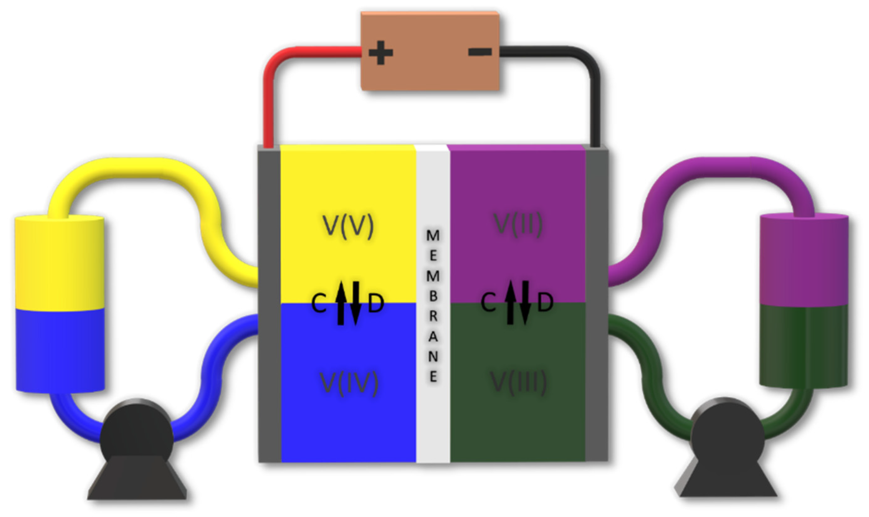
A schematic of a VRFB is seen in Figure 1. During discharge and on the positive side of the cell, VO2+ is reduced to VO2+
while in the negative half-cell, V2+ is oxidized to V3+
This gives the net reaction
To illustrate easier, the oxidation states of vanadium, V2+, V3+, VO2+ and VO2+ are hereinafter denoted as V(II), V(III), V(IV) and V(V), respectively.
In principle, the electrolytes can be recycled through remixing and re-separation, giving the electrolyte an unlimited cycle life [9,10]. Other advantages include the possibility to use fast and slow discharging rates with a high depth of discharge (DoD), system cooling by heat extraction of the electrolyte, a long calendar life, no damage by overcharging and the good electrochemical kinetics of vanadium [9].
Although showing favorable properties for medium- and large-scale energy storage, the overall cost of the system is far away from the target capital cost of USD 150 kWh−1 that was suggested by the United States Department of Energy in 2015 [11]. Currently, the average capital costs of a VRFB are estimated to be USD 300–800 kWh−1 comprised of the electrolyte, stack and balance of plant costs [2,12]. The cell stack price is primarily linked to the high cost of Nafion® membrane. Thus, research for novel cost-efficient materials and components is essential to make the VRFB more suitable for commercial applications.
Cation exchange membranes (CEMs) have been used in VRFB applications since the 1980s [13]. One commonly used CEM for VRFB applications is the perfluorosulfonic acid (PFSA) membrane, Nafion®. Nafion combines a hydrophobic Teflon backbone with high chemical stability, high mechanical strength and good thermal stability, with hydrophilic sulfonic acid side groups (-SO3H) that allow for high ion conductivity in aqueous media. When exposed to aqueous electrolytes, the sulfonic groups are hydrolyzed, allowing for hydrated protons and other cations to permeate through the membrane [1,14]. The ion transport in Nafion is described by Li et al. through the water channel model, where sulfonic functional groups in Nafion self-organize into micelles to form water channels in the membrane of approximately 2.5 nm in diameter. Through these channels, small-sized cations such as protons are then transported across the membrane [13].
Although having many desirable properties, the main drawbacks of Nafion in VRFBs include:
As explained, the low ion selectivity of Nafion in VRFB applications is a property caused by hydration of the acidic functional groups, where hydrophilic clusters allow for positively charged hydrated vanadium ions to pass through the membrane. Therefore, several studies have focused on reducing electrolyte crossover through Nafion membranes by blocking the hydrophilic clusters using inorganic nanoparticles (e.g., SiO2, TiO2 and graphene oxide) or organic nanoparticles (e.g., polytetrafluoroethylene, tetraethoxysilane, diethoxydimethylsilane and polyethyleneimine) [13,14,15,16,17,18,19,20]. The attempts were successful in reducing vanadium permeation. However, this was at the cost of reduced ionic conductivity.
Non-fluorinated CEMs have also been developed to overcome the challenges of Nafion [13,14,21]. As well as lower costs, some of them can also offer excellent mechanical and chemical stability combined with high ion selectivity. One example is sulfonated aromatic polymers with less connected regions of functional groups that prevent clustering and allow for better ion selectivity than Nafion [13,22]. Additionally, Z. Mai et al. compared sulfonated poly(tetramethydiphenyl ether ether ketone) (SPEEK) membranes with Nafion 115, and found that the SPEEK showed one order of magnitude lower vanadium ion permeability [22]. In addition, the low-cost SPEEK membranes demonstrated comparable EE (>84%) to that of Nafion, with a higher CE (>97%) and kept a stable performance for 80 charge/discharge cycles. The self-discharge test also showed two times longer cell duration in terms of time compared to that of Nafion 115.
Another approach is to use anion exchange membranes (AEMs) as they generally exhibit a lower crossover of vanadium than CEMs [2,14,23,24]. This is due to a more substantial Donnan exclusion effect initiated by cationic functional groups that generate an electrostatic field repelling positively charged vanadium ions [11].
AEMs generally have a higher area resistance than CEMs with similar IEC due to the lower mobility of anions compared to protons [13,25]. An example of this is the study on the physicochemical and electrochemical performance of a poly(phenylene oxide)-based Im-bPPO AEM in the VRFB system that showed a CE higher than that when Nafion membrane was used, likely associated with the much lower V(IV) ion permeability and higher ion selectivity. However, applied current density and voltage and energy efficiencies were lower for the Im-bPPO membrane, which the authors attribute to higher area resistance of the membrane [26].
Commonly used cationic groups are ammonium, imidazolium, pyridinium, piperidinium and guanidinium. Among them, piperidinium and imidazolium have shown substantial resistance towards degradation when exposed to harsh conditions [12,27,28]. In addition, imidazolium groups with heterocyclic structures possess good chemical stability mainly due to their aromaticity. The latter is because of a conjugated system between π-bonds on the double bond and electron pair on the nitrogen [29,30]. The conjugated system is lower in energy; in other words, it is more stable.
The AEMs synthesized via incorporating the imidazolium functional groups into the ether-free polyaryl backbone have shown promising chemical, thermal and mechanical stabilities in harsh alkaline conditions in fuel cells and water electrolysis systems [28,29,31,32,33,34,35,36].
Imidazolium-based membranes have also been tested in VRFB applications where a VRFB using a 30 μm hexamethyl-p-terphenyl poly(benzimidazolium) membrane showed low self-discharge and resistance, with a CE of over 99.4% and EE between 80.6 and 74.2% at 15 mA cm−2 for 45 cycles [27]. Recently, imidazolium-based AEMs, called Aemion™, have been commercially available for VRFB systems. To the best of our knowledge, this is the first work aimed at investigating the electrochemical performance of Aemion™ membranes in VRFBs.
2. Materials and Methods
2.1. Materials and Chemicals
Vanadium electrolyte mixture consisting of 1.6 M V(III)/V(IV) in 2 M H2SO4 was purchased from Gesellschaft für Elektrometallurgie mbH (GfE). Vanadium (IV) oxide sulfate hydrate (VOSO4 · xH2O) and Magnesium Sulfate (MgSO4) were purchased from Sigma-Aldrich. Aemion™ AEMs developed for alkaline water electrolysis (AF1-HNN5-50-X, AF1-HNN8-50-X) and for VRFBs (AF1-ENN8-50-X) were purchased from Ionomr. From now on, for simplicity, the above-mentioned AEMs will be denoted as HNN5, HNN8 and ENN8. Nafion 211 and 212 cation exchange membranes and Sigracet 29 BA carbon paper electrodes were purchased from the FuelCellStore.
2.2. Flow Battery Tests
The RFB tests were conducted using an electrochemical flow cell (Fuel Cell Technologies) consisting of two current collectors and two Poco graphite plates with a serpentine flow field. The cell performance was optimized to achieve the lowest cell area-specific resistance by varying the number of electrode layers and flow rate. Two layers of carbon paper electrodes (thermally pretreated at 500 °C for 1 h in air atmosphere) with a surface area of 5 cm2 and thickness of 0.22 mm were used on each side of the cell and the system was sealed using two Viton® gaskets with a thickness of 0.25 mm each. In addition, all membranes were pretreated in 2 M H2SO4 for 24 h before cycling tests. Unless anything else is stated, the assembling bolts were tightened using a torque wrench with a momentum of 6 Nm. The electrolytes (14 mL each) were pumped into the system using a Longer BT-6002J dual-channel peristaltic pump at a rate of 200 rpm at room temperature. To prevent air oxidation of V(II), the negative electrolyte was constantly purged with nitrogen during the tests to ensure an oxygen-free environment. The charge/discharge tests were carried out using a Landt Systems CT2001A 8-channel battery tester in a four-probe configuration and considering cutoff voltages of 1.7 and 0.8 V for charging and discharging, respectively.
Rate performance tests were conducted by running five cycles at current densities between 100–300 mA cm−2 with cutoff voltages of 0.8 to 1.7 V.
The total resistance of the VRFB system was calculated by measuring polarization curves with increasing current density from 2–400 mA cm−2 at 50% SoC before and after the long-term cycling tests.
2.3. Area-Specific Resistance and Ionic Conductivity
All membranes were soaked in 2 M H2SO4 for one day before the area-specific resistance (ASR) measurement. Electrochemical impedance spectroscopy (EIS) technique was used to measure the ASR using a four-probe VersaSTAT 4 workstation at a frequency range of 1 MHz–100 Hz with an amplitude of 10 mV. A fresh 2 M H2SO4 solution was circulated to both sides of the RFB system. The high-frequency resistance (HFR) of the RFB system with (HFR1) and without (HFR2) membrane was measured, where the difference between the resistances mentioned above gives the pure HFR of each membrane. The ASR and ionic conductivity (σ, mS cm−1) of the membranes were calculated using Equations (4) and (5) below
Here, and denote the thickness and the active area of the membrane, respectively.
2.4. Self-Discharge Test
To measure the self-discharge duration of the VRFB, a lower flow rate of 100 rpm (60 mL min−1) and tightening momentum of 5 Nm were used in order to decrease mechanical stress on the membrane. When assembled, the cell was charged using constant current charging, with a cutoff voltage of 1.7 V in steps from 200–4 mA cm−2 to obtain 100% state of charge (SoC). The open-circuit voltage (OCV) and time were thereafter measured until a voltage close to 0 V was reached.
2.5. Vanadium (IV) Permeation
Due to the unique absorbance spectra of each vanadium oxidation state, a standard method to detect vanadium concentrations in solutions is UV–VIS spectroscopy. A glass diffusion cell, with two compartments (90 mL each) and a circular flow field of 12.57 cm2, was used to study vanadium permeability through the membrane. The left chamber was filled with a 1 M V(IV) in 2 M H2SO4 solution and the right chamber with 1 M MgSO4 in 2 M H2SO4. The solutions on each side were constantly stirred during the experiment. Samples of 1 mL were taken every 24 h from the left chamber and subjected to UV–VIS spectroscopy analysis. It should be noted that 1 mL was taken from the right chamber at each time interval to minimize osmotic effects. The concentration of V(IV) was determined from a calibration curve.
The permeability (cm2 min−1) of V(IV) through the membrane can be determined using Equation (6)
where L is the thickness of the membrane, V is the volume of the chamber, CL is the initial concentration of V(IV) in the left chamber, CR is the V(IV) concentration in the right chamber at the time of t and A is the active area of the membrane.
2.6. Oxidation Stability
The oxidative stability of the membranes was studied in a V(V)/H2SO4 solution. Membrane oxidation by V(V) will lead to the formation of V(IV) and the extent of oxidation can thereby be quantified from the abundance of V(IV) ions. In this study, a membrane with a geometrical area of 4 cm2 was immersed in a 10 mL 1.6 M V(V) solution for 800 h and the concentration of V(IV) was measured over time by UV–VIS spectroscopy. Moreover, the degree of oxidation of the membrane was analyzed by NMR after 800 h immersion.
2.7. Water Uptake
Water uptake was measured by weighing a piece of the membrane with a geometrical area of 5 cm2 and immersing it in 2 M H2SO4 for 24 h, followed by immersion in deionized water for 2 h to wash off the excess acid solution and finally drying it in vacuum at 50 °C for 24 h. The membrane was weighed immediately after drying (, dry weight in sulfate form). The weight of the membrane in the wet state () was obtained by: (i) immersing the same membrane sample in deionized water for 24 h; (ii) wiping off the surface moisture with filter paper immediately before weighing the sample.
The water uptake can be calculated using Equation (7)
3. Results and Discussion
The performance of five membranes, including two Nafion® CEMs and three Aemion™ AEMs, was investigated in the VRFB setup. Some basic properties of the membranes are displayed in Table 1. It is important to note that the ionic conductivity of Nafion 212 is due to the proton exchange through negatively charged sulfonic acid groups. However, the simultaneous transport of (bi)sulfate anions and protons determines the ionic conductivity of AEMs. Therefore, the transport number of protons is a critical factor affecting the ionic conductivity of AEMs. For instance, the higher ionic conductivity of the HNN8 and ENN8 is mainly due to the higher proton transport number in those membranes compared to HNN5 [37].
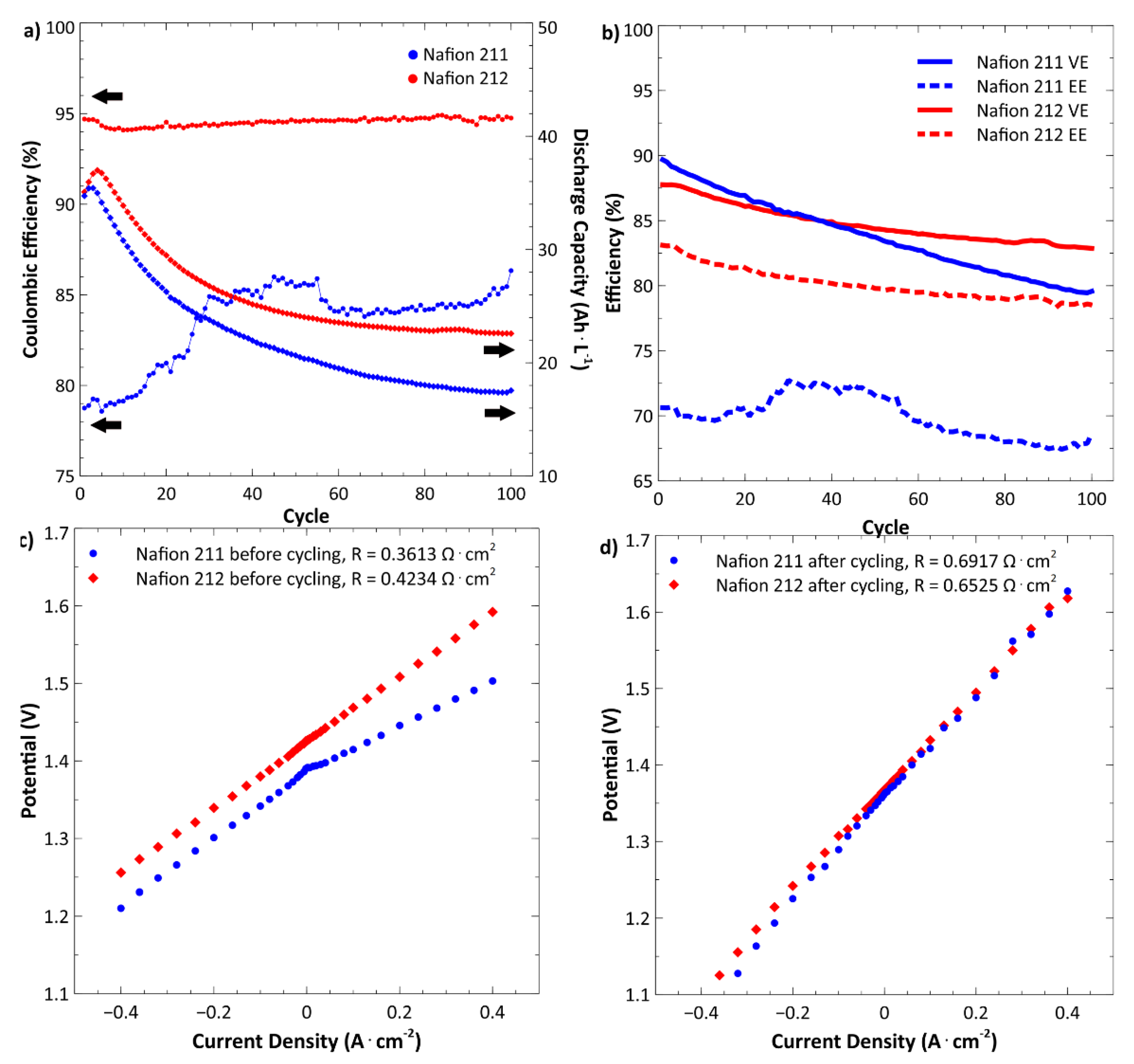
Figure 2a shows the VRFB performance using Nafion membranes with two different thicknesses. The discharge capacity shows an increase at the first couple of cycles using both Nafion membranes and is explained by the fast non-equilibrium electrolyte crossover in the initial cycles [38]. Over 100 cycles, the discharge capacity attenuation is 49.5% and 35.6% for Nafion 211 and 212, respectively. The severe capacity losses are mainly because of the poor ion selectivity of Nafion membranes, resulting in unwanted crossover of vanadium ions and self-discharge reactions [13,14,39]. On the other hand, the larger capacity loss in the case of Nafion 211 is due to the lower thickness. It should also be mentioned that the net crossover is from the negative to the positive side using Nafion membranes, mainly due to the high permeation rate of V(II) and V(III) compared to V(IV) and V(V) [12,23,40,41,42].
The average coulombic efficiency (CE) when using the thinner Nafion 211 is 83.54% compared to 94.54% for the thicker Nafion 212. This is expected as the electrolyte crossover has a negative impact on CE and is inversely related to the membrane thickness [43]. Using Nafion 211, the CE increases rapidly during the first 20 cycles and stabilizes afterward. Deactivation of the membrane is likely the reason for low CE in the initial cycles [44].
As seen in Figure 2b, the voltage efficiency (VE) shows a descending trend using both membranes; however, it is more noticeable for Nafion 211. The combined effect of both CE and VE can be seen on the energy efficiency (EE).
The polarization curves (Figure 2c) show that the total resistance of the VRFB using Nafion 211 is lower than when Nafion 212 is used. As all experimental conditions are the same except for the membrane, therefore, the difference in total resistance is mainly attributed to the membrane resistance. This is precisely why the VE of the VRFB is initially Higher when Nafion 211 is used (Figure 2b). However, after around 35 cycles, the VE decreases more rapidly compared to Nafion 212 as the increase in membrane resistance is more remarkable for Nafion 211. Polarization curves after 100 cycles (Figure 2d) confirm the latter.
As a result, the total resistance of the VRFB using Nafion 211 increases 47% after 100 cycles compared to 35% when using Nafion 212. The resistance increase is most likely due to the increased uptake of vanadium ions and the subsequent reduced water uptake of membranes during cycling.
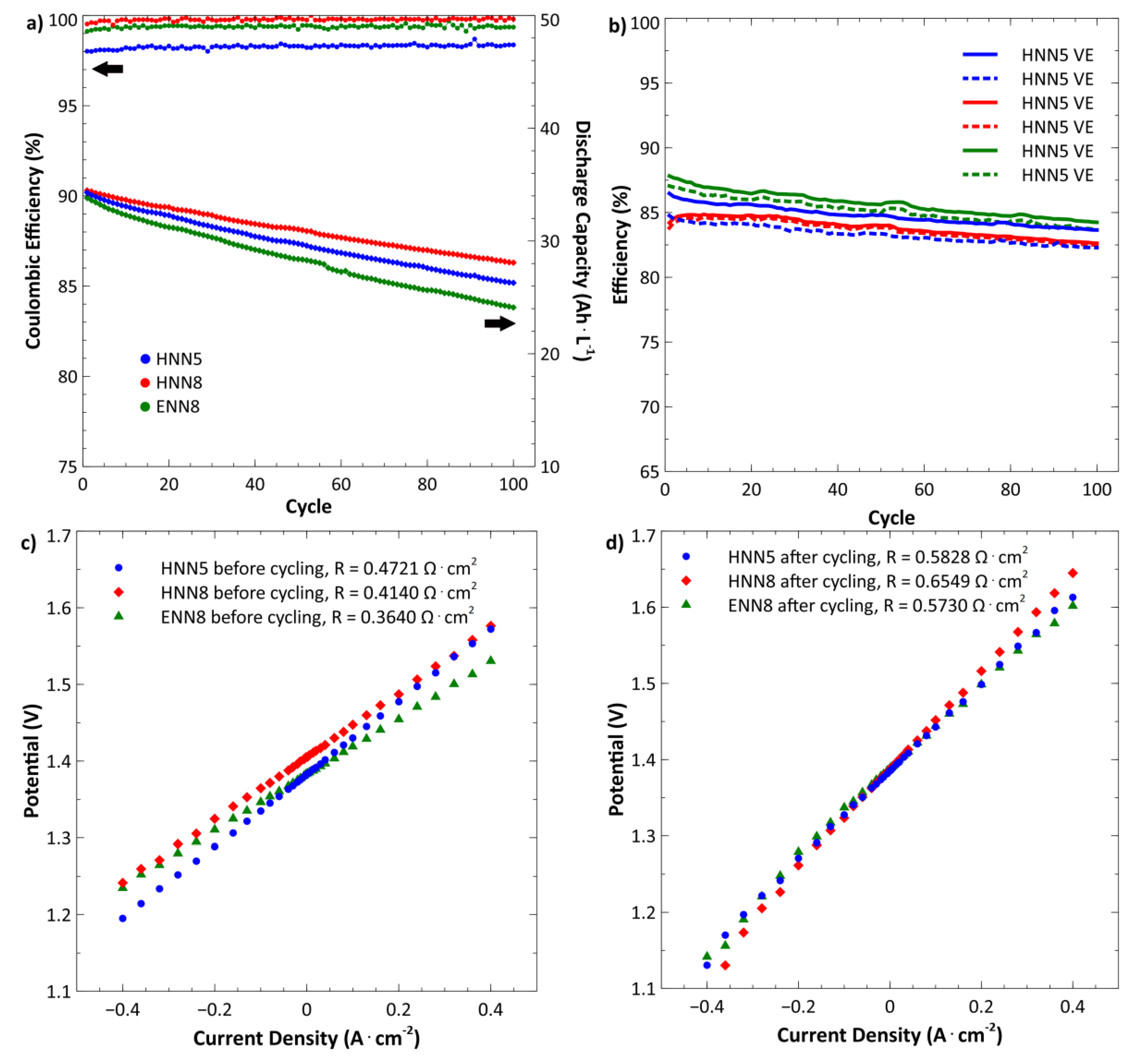
Figure 3 shows the electrochemical performance of the VRFB using AemionTM AEMs. There is no initial peak in the discharge capacity curves, unlike the Nafion membranes. Moreover, lower capacity losses (˂30%) were achieved using AEMs due to a stronger Donnan exclusion effect. Interestingly, the VRFB using HNN8 showed the lowest capacity loss (18.6%) compared to HNN5 (23.3%) and ENN8 (28.7%), even though HNN8 exhibited the Highest water uptake. The relatively high capacity loss could be attributed to the high water uptake rates of AEMs (Table 1), which facilitate vanadium crossover. Generally, using AEMs in VRFB, the net crossover is from the positive to the negative side due to negatively charged complexes formed by V(IV), V(V) and sulfate ions (e.g., VO2SO4−) that pass through the membrane. The latter is confirmed by the volumetric increase on the negative side, 18% for the VRFB using ENN8 and 11% for HNN5 and HNN8.
The VRFB based on HNN8 and ENN8 membranes shows a similar average CE of over 99%. Using HNN5, a slightly lower average CE (98.28%) was achieved. Although high CE is an indication of low crossover, the capacity loss over 100 cycles shows a different trend. Therefore, to avoid any possible confusion, it should be mentioned that the high CE is due to the high applied current density for cycling.
The VRFB using ENN8 shows an excellent VE (Figure 3c) and the lowest total resistance (Figure 3d), thanks to the high ionic conductivity and water uptake (Table 1). The combined effect of CE and VE, energy efficiency, is seen in Figure 3b, where the VRFB using ENN8 shows an average EE of 85.15% compared to 83.65% and 83.29% when using HNN8 and HNN5, respectively.
Table 2 shows a summary of the VRFB performance using various membranes. Given its high conductivity and excellent efficiencies (CE, VE and EE) of the VRFB at a current density of 200 mA cm−2, ENN8 was selected for extended comparison versus Nafion 212.
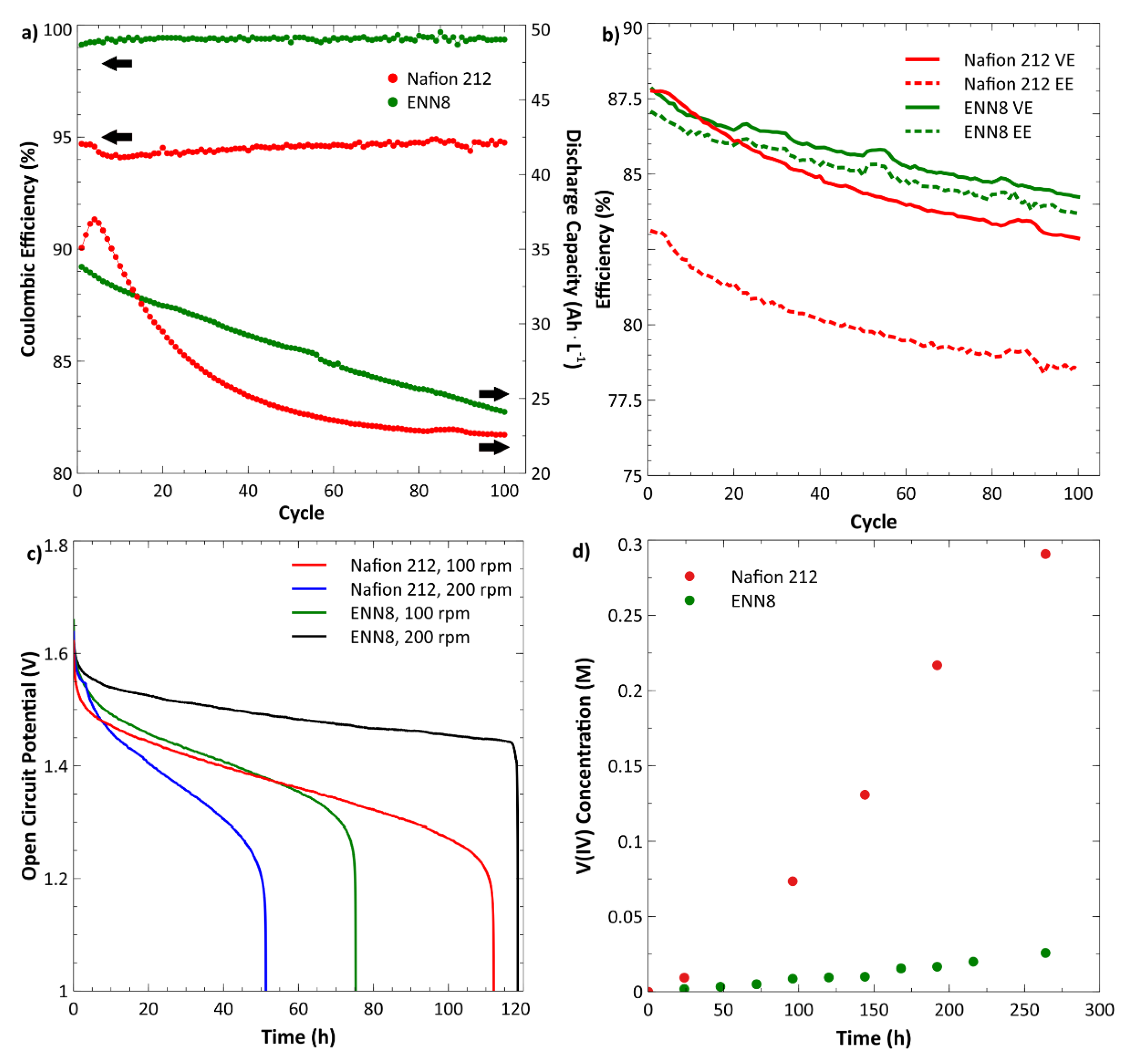
Figure 4 shows an extended comparison of the electrochemical performance of Nafion 212 and ENN8. The VRFB using ENN8 shows an excellent average CE of 99.38% over 100 cycles. Although having excellent CE, a relatively high capacity loss of 28.7% is still seen over 100 cycles, which is related to the relatively high water uptake. Due to the crossover in the mentioned directions for different membranes, a volumetric increase of 18% on the negative side and 7% on the positive side after 100 cycles was observed using ENN8 and Nafion 212, respectively.
The open-circuit voltage (OCV) over time was measured and is shown in Figure 4c. The VRFB using Nafion 212 demonstrates a self-discharge time of 110 h compared to 75 h using ENN8 at a flow rate of 100 rpm. Interestingly, running the OCV test at an elevated flow (200 rpm), the self-discharge time decreased to below 60 h for Nafion 212, while it increased to over 110 h for ENN8.
Different OCV results by changing the flow rate suggest different crossover mechanisms for the membranes, where Nafion 212 could be more prone to crossover caused by an increased pressure gradient from the increased flow rate [45]. A similar effect was reported by Sun et al., where Nafion 117 membranes showed longer self-discharge time by increasing the flow rate [46].
Figure 4d shows the V(IV) concentration versus time measured in the diffusion cell. The permeation rate of V(IV) through Nafion 212 (6.82 × 10⁻⁷ cm2 min−1) is more than one order of magnitude higher than that through ENN8 (5.74 × 10⁻⁸ cm2 min−1). These results are in agreement with capacity losses and coulombic efficiencies achieved using Nafion and ENN8.
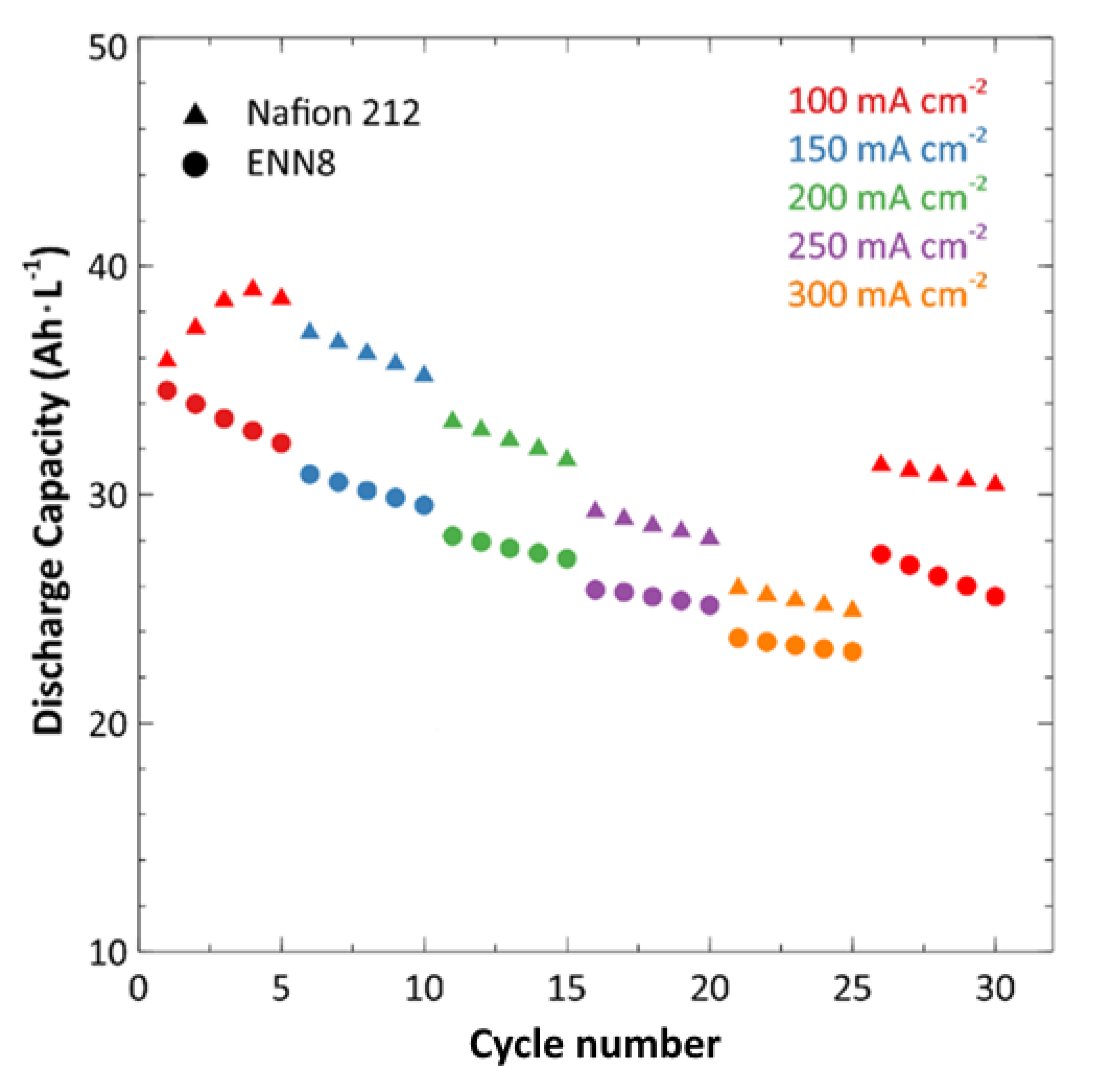
Rate performance analysis of the VRFB using Nafion 212 and ENN8 was conducted at different current densities (Figure 5). The analysis shows the discharge capacity stability of the VRFB by suddenly changing the current. It should be mentioned that the theoretical capacity of the VRFB considering the above-mentioned experimental conditions is ~43 Ah L−1. The VRFB using both membranes shows similar stability. The discharge capacity has a little falling rate at each current density. Larger capacities were achieved using Nafion 212 than ENN8 for all current densities as the VRFB was operated only for five cycles. A similar trend is seen in Figure 4a, where in the first 15 cycles, higher discharge capacities were achieved using Nafion 212. By increasing the current density, the reduction in discharge capacity for the VRFB using Nafion 212 is more remarkable, mainly due to the higher total cell resistance.
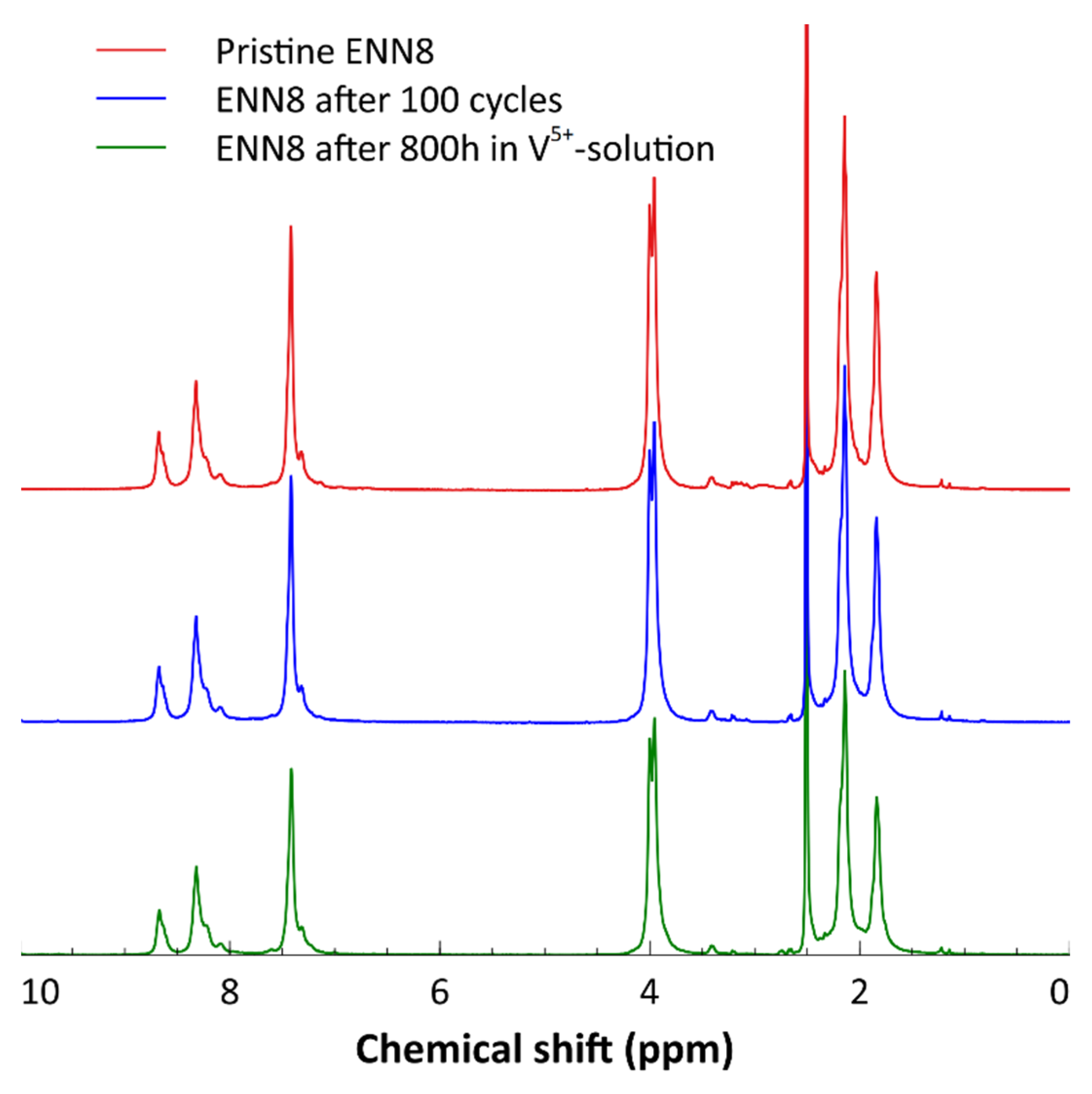
Finally, the (electro)chemical degradation of the ENN8 was studied by 1H NMR analysis. Figure 6 compares the spectra of three membrane samples: pristine ENN8, the ENN8 after 100 cycles and ENN8 after immersion in 1.6 M highly oxidizing V(V) solution for 800 h. Considering the higher shifts in the aromatic region, no substantial difference can be seen between the membranes, indicating that ENN8 possesses good chemical stability for VRFB applications.
The AEMs showed good (electro)chemical performance but relatively high capacity loss. The main drawback is the high water uptake in acidic media. Therefore, future research should focus on better understanding the crossover mechanisms in the membrane by investigating the structure and elements that influence water uptake, such as the degree of methylation. Furthermore, the mechanical stability of the Aemion membranes could be further studied as they, in some cases, showed damage upon disassembly, in contrast to the Nafion membranes.
4. Conclusions
In this study, the (electro)chemical performance of five ion-exchange membranes (IEMs) was investigated for vanadium redox flow battery application. Three AemionTM anion exchange membranes showed good performance during cycling of the VRFB at 200 mA cm−2 for over 100 cycles. Higher efficiencies and lower total resistance were achieved for the VRFB using AEMs compared to Nafion 211 and 212. Further comparison versus Nafion 212 revealed that the VRFB using AF1-ENN8-50-X showed an average CE of 99.38%, an excellent VE of 85.69% and EE of 85.16%. In addition, the NMR analysis of AF1-ENN8-50-X after 100 cycles exhibited good chemical stability with almost no degradation. Furthermore, AF1-ENN8-50-X showed excellent oxidation stability after 800 h in V(V) solution.
On the other hand, a relatively high capacity loss of 28.7% was observed using AF1-ENN8-50-X, attributed to the high water uptake, which facilitates permeation of ions such as VO2SO4−.
Considering the achieved results in this study, the research on (electro)chemical performance of AemionTM AEMs in VRFBs is an interesting topic that requires further investigation. The primary strategy for future research should be on lowering the water uptake of AEMs while preserving a good ionic conductivity. Furthermore, the mechanical stability of the Aemion membranes should also be addressed, as they, in some cases, showed damage upon disassembly.
Author Contributions
Conceptualization, A.K.; methodology, E.L. and A.K.; validation, E.L., A.K. and R.W.L.; investigation, E.L. and A.K.; data curation, E.L., A.K. and R.W.L.; writing—original draft preparation, E.L.; writing—review and editing, E.L., A.K. and R.W.L.; supervision, A.K. and R.W.L. All authors have read and agreed to the published version of the manuscript.
Funding
This work was supported by Batterifonden via Swedish Energy Agency and StandUp for Energy (Grant agreement no. 45515-1).
Data Availability Statement
Not applicable.
Acknowledgments
Thanks to Patric Jannasch at Lund University for providing helpful input.
Conflicts of Interest
The authors declare that they have no known competing financial interest or personal relationships that could have appeared to influence the work reported in this paper.
References
- Shi, Y.; Eze, C.; Xiong, B.; He, W.; Zhang, H.; Lim, T.M.; Ukil, A.; Zhao, J. Recent development of membrane for vanadium redox flow battery applications: A review. Appl. Energy 2019, 238, 202–224. [Google Scholar] [CrossRef]
- Leung, P.; Li, X.; Ponce de León, C.; Berlouis, L.; Low, C.T.J.; Walsh, F.C. Progress in redox flow batteries, remaining challenges and their applications in energy storage. RSC Adv. 2012, 2, 10125–10156. [Google Scholar] [CrossRef]
- Choi, C.; Kim, S.; Kim, R.; Choi, Y.; Kim, S.; Jung, H.Y.; Yang, J.H.; Kim, H.T. A review of vanadium electrolytes for vanadium redox flow batteries. Renew. Sustain. Energy Rev. 2017, 69, 263–274. [Google Scholar] [CrossRef]
- Ding, C.; Zhang, H.; Li, X.; Liu, T.; Xing, F. Vanadium Flow Battery for Energy Storage: Prospects and Challenges. J. Phys. Chem. Lett. 2013, 4, 1281–1294. [Google Scholar] [CrossRef] [PubMed]
- Skyllas-Kazacos, M.; Menictas, C.; Lim, T. Electricity Transmission, Distribution and Storage Systems; Melhem, Z., Ed.; Woodhead Publishing: Sawston, UK, 2013; pp. 398–441. [Google Scholar] [CrossRef]
- Sánchez-Díez, E.; Ventosa, E.; Guarnieri, M.; Trovò, A.; Flox, C.; Marcilla, R.; Soavi, F.; Mazur, P.; Aranzabe, E.; Ferret, R. Redox flow batteries: Status and perspective towards sustainable stationary energy storage. J. Power Sources 2021, 481, 228804. [Google Scholar] [CrossRef]
- Arenas, L.F.; de León, C.P.; Walsh, F.C. Redox flow batteries for energy storage: Their promise, achievements and challenges. Curr. Opin. Electrochem. 2019, 16, 117–126. [Google Scholar] [CrossRef]
- Rychcik, M.; Skyllas-Kazacos, M. Characteristics of a new all-vanadium redox flow battery. J. Power Sources 1988, 22, 59–67. [Google Scholar] [CrossRef]
- Weber, A.Z.; Mench, M.M.; Meyers, J.P.; Ross, P.N.; Gostick, J.T.; Liu, Q. Redox flow batteries: A review. J. Appl. Electrochem. 2011, 41, 1137–1164. [Google Scholar] [CrossRef] [Green Version]
- Yuan, X.-Z.; Song, C.; Platt, A.; Zhao, N.; Wang, H.; Li, H.; Fatih, K.; Jang, D. A review of all-vanadium redox flow battery durability: Degradation mechanisms and mitigation strategies. Int. J. Energy Res. 2019, 43, 6599–6638. [Google Scholar] [CrossRef]
- Zeng, L.; Zhao, T.S.; Wei, L.; Jiang, H.R.; Wu, M.C. Anion exchange membranes for aqueous acid-based redox flow batteries: Current status and challenges. Appl. Energy 2019, 233, 622–643. [Google Scholar] [CrossRef]
- Khataee, A.; Pan, D.; Olsson, J.S.; Jannasch, P.; Lindström, R.W. Asymmetric cycling of vanadium redox flow batteries with a poly(arylene piperidinium)-based anion exchange membrane. J. Power Sources 2021, 483, 229202. [Google Scholar] [CrossRef]
- Li, X.; Zhang, H.; Mai, Z.; Zhang, H.; Vankelecom, I. Ion exchange membranes for vanadium redox flow battery (VRB) applications. Energy Environ. Sci. 2011, 4, 1147–1160. [Google Scholar] [CrossRef]
- Doan, T.N.L.; Hoang, T.K.A.; Chen, P. Recent development of polymer membranes as separators for all-vanadium redox flow batteries. RSC Adv. 2015, 5, 72805–72815. [Google Scholar] [CrossRef]
- Teng, X.; Zhao, Y.; Xi, J.; Wu, Z.; Qiu, X.; Chen, L. Nafion/organically modified silicate hybrids membrane for vanadium redox flow battery. J. Power Sources 2009, 189, 1240–1246. [Google Scholar] [CrossRef]
- Teng, X.; Dai, J.; Su, J.; Zhu, Y.; Liu, H.; Song, Z. A high performance polytetrafluoroethene/Nafion composite membrane for vanadium redox flow battery application. J. Power Sources 2013, 240, 131–139. [Google Scholar] [CrossRef]
- Xi, J.; Wu, Z.; Qiu, X.; Chen, L. Nafion/SiO2 hybrid membrane for vanadium redox flow battery. J. Power Sources 2007, 166, 531–536. [Google Scholar] [CrossRef]
- Teng, X.; Zhao, Y.; Xi, J.; Wu, Z.; Qiu, X.; Chen, L. Nafion/organic silica modified TiO2 composite membrane for vanadium redox flow battery via in situ sol–gel reactions. J. Membr. Sci. 2009, 341, 149–154. [Google Scholar] [CrossRef]
- Lee, K.J.; Chu, Y.H. Preparation of the graphene oxide (GO)/Nafion composite membrane for the vanadium redox flow battery (VRB) system. Vacuum 2014, 107, 269–276. [Google Scholar] [CrossRef]
- Luo, Q.; Zhang, H.; Chen, J.; Qian, P.; Zhai, Y. Modification of Nafion membrane using interfacial polymerization for vanadium redox flow battery applications. J. Membr. Sci. 2008, 311, 98–103. [Google Scholar] [CrossRef]
- Maurya, S.; Shin, S.-H.; Kim, Y.; Moon, S.-H. A review on recent developments of anion exchange membranes for fuel cells and redox flow batteries. RSC Adv. 2015, 5, 37206–37230. [Google Scholar] [CrossRef]
- Mai, Z.; Zhang, H.; Li, X.; Bi, C.; Dai, H. Sulfonated poly(tetramethydiphenyl ether ether ketone) membranes for vanadium redox flow battery application. J. Power Sources 2011, 196, 482–487. [Google Scholar] [CrossRef]
- Prifti, H.; Parasuraman, A.; Winardi, S.; Lim, T.M.; Skyllas-Kazacos, M. Membranes for redox flow battery applications. Membranes 2012, 2, 275–306. [Google Scholar] [CrossRef] [PubMed] [Green Version]
- Varcoe, J.R.; Atanassov, P.; Dekel, D.R.; Herring, A.M.; Hickner, M.A.; Kohl, P.A.; Kucernak, A.R.; Mustain, W.E.; Nijmeijer, K.; Scott, K.; et al. Anion-exchange membranes in electrochemical energy systems. Energy Environ. Sci. 2014, 7, 3135–3191. [Google Scholar] [CrossRef] [Green Version]
- Gubler, L. Membranes and separators for redox flow batteries. Curr. Opin. Electrochem. 2019, 18, 31–36. [Google Scholar] [CrossRef]
- Roh, S.-H.; Lim, M.-H.; Sadhasivam, T.; Jung, H.-Y. Investigation on physico-chemical and electrochemical performance of poly(phenylene oxide)-based anion exchange membrane for vanadium redox flow battery systems. Electrochim. Acta 2019, 325, 134944. [Google Scholar] [CrossRef]
- Shanahan, B.; Böhm, T.; Britton, B.; Holdcroft, S.; Zengerle, R.; Vierrath, S.; Thiele, S.; Breitwieser, M. 30 μm thin hexamethyl-p-terphenyl poly(benzimidazolium) anion exchange membrane for vanadium redox flow batteries. Electrochem. Commun. 2019, 102, 37–40. [Google Scholar] [CrossRef]
- Wright, A.G.; Fan, J.; Britton, B.; Weissbach, T.; Lee, H.-F.; Kitching, E.A.; Peckham, T.J.; Holdcroft, S. Hexamethyl-p-terphenyl poly(benzimidazolium): A universal hydroxide-conducting polymer for energy conversion devices. Energy Environ. Sci. 2016, 9, 2130–2142. [Google Scholar] [CrossRef]
- Holdcroft, S.; Fan, J. Sterically-encumbered ionenes as hydroxide ion-conducting polymer membranes. Curr. Opin. Electrochem. 2019, 18, 99–105. [Google Scholar] [CrossRef]
- Long, H.; Pivovar, B. Hydroxide Degradation Pathways for Imidazolium Cations: A DFT Study. J. Phys. Chem. C 2014, 118, 9880–9888. [Google Scholar] [CrossRef]
- Aili, D.; Hansen, M.K.; Renzaho, R.F.; Li, Q.; Christensen, E.; Jensen, J.O.; Bjerrum, N.J. Heterogeneous anion conducting membranes based on linear and crosslinked KOH doped polybenzimidazole for alkaline water electrolysis. J. Membr. Sci. 2013, 447, 424–432. [Google Scholar] [CrossRef] [Green Version]
- Coppola, R.E.; Herranz, D.; Escudero-Cid, R.; Ming, N.; D’Accorso, N.B.; Ocón, P.; Abuin, G.C. Polybenzimidazole-crosslinked-poly(vinyl benzyl chloride) as anion exchange membrane for alkaline electrolyzers. Renew. Energy 2020, 157, 71–82. [Google Scholar] [CrossRef]
- Thomas, O.D.; Soo, K.J.W.Y.; Peckham, T.J.; Kulkarni, M.P.; Holdcroft, S. A Stable Hydroxide-Conducting Polymer. J. Am. Chem. Soc. 2012, 134, 10753–10756. [Google Scholar] [CrossRef] [PubMed]
- Wright, A.G.; Holdcroft, S. Hydroxide-Stable Ionenes. ACS Macro Lett. 2014, 3, 444–447. [Google Scholar] [CrossRef]
- Fortin, P.; Khoza, T.; Cao, X.; Martinsen, S.Y.; Barnett, A.O.; Holdcroft, S. High-performance alkaline water electrolysis using Aemion™ anion exchange membranes. J. Power Sources 2020, 451, 227814. [Google Scholar] [CrossRef]
- Pushkareva, I.V.; Pushkarev, A.S.; Grigoriev, S.A.; Modisha, P.; Bessarabov, D.G. Comparative study of anion exchange membranes for low-cost water electrolysis. Int. J. Hydrogen Energy 2020, 45, 26070–26079. [Google Scholar] [CrossRef]
- Seo, S.-J.; Kim, B.-C.; Sung, K.-W.; Shim, J.; Jeon, J.-D.; Shin, K.-H.; Shin, S.-H.; Yun, S.-H.; Lee, J.-Y.; Moon, S.-H. Electrochemical properties of pore-filled anion exchange membranes and their ionic transport phenomena for vanadium redox flow battery applications. J. Membr. Sci. 2013, 428, 17–23. [Google Scholar] [CrossRef]
- Mu, D.; Zhao, Y.; Yu, L.; Liu, L.; Xi, J. Asymmetric vanadium flow batteries: Long lifespan via an anolyte overhang strategy. Phys. Chem. Chem. Phys. 2017, 19, 29195–29203. [Google Scholar] [CrossRef]
- Schwenzer, B.; Zhang, J.; Kim, S.; Li, L.; Liu, J.; Yang, Z. Membrane Development for Vanadium Redox Flow Batteries. ChemSusChem 2011, 4, 1388–1406. [Google Scholar] [CrossRef]
- Yang, X.-G.; Ye, Q.; Cheng, P.; Zhao, T.S. Effects of the electric field on ion crossover in vanadium redox flow batteries. Appl. Energy 2015, 145, 306–319. [Google Scholar] [CrossRef]
- Hao, L.; Wang, Y.; He, Y. Modeling of Ion Crossover in an All-Vanadium Redox Flow Battery with the Interfacial Effect at Membrane/Electrode Interfaces. J. Electrochem. Soc. 2019, 166, A1310–A1322. [Google Scholar] [CrossRef]
- Haisch, T.; Ji, H.; Holtz, L.; Struckmann, T.; Weidlich, C. Half-Cell State of Charge Monitoring for Determination of Crossover in VRFB—Considerations and Results Concerning Crossover Direction and Amount. Membranes 2021, 11, 232. [Google Scholar] [CrossRef] [PubMed]
- Jeong, S.; Kim, L.-H.; Kwon, Y.; Kim, S. Effect of nafion membrane thickness on performance of vanadium redox flow battery. Korean J. Chem. Eng. 2014, 31, 2081–2087. [Google Scholar] [CrossRef]
- Park, J.H.; Park, J.J.; Park, O.O.; Yang, J.H. Capacity Decay Mitigation by Asymmetric Positive/Negative Electrolyte Volumes in Vanadium Redox Flow Batteries. ChemSusChem 2016, 9, 3181–3187. [Google Scholar] [CrossRef] [PubMed]
- Agar, E.; Knehr, K.W.; Chen, D.; Hickner, M.A.; Kumbur, E.C. Species transport mechanisms governing capacity loss in vanadium flow batteries: Comparing Nafion® and sulfonated Radel membranes. Electrochim. Acta 2013, 98, 66–74. [Google Scholar] [CrossRef]
- Sun, J.; Shi, D.; Zhong, H.; Li, X.; Zhang, H. Investigations on the self-discharge process in vanadium flow battery. J. Power Sources 2015, 294, 562–568. [Google Scholar] [CrossRef]
Figure 1.
Schematic of a vanadium redox flow battery and its reactions during charge (C) and discharge (D).
Figure 1.
Schematic of a vanadium redox flow battery and its reactions during charge (C) and discharge (D).

Figure 2.
Charge/Discharge performance of the VRFB cell for Nafion 211 and 212 membranes over 100 cycles showing (a) Coulombic Efficiency and Discharge Capacity, (b) Voltage and Energy Efficiency, (c) Polarization curves prior to cycling, (d) Polarization curves after cycling. Experimental conditions: 1.6 M V(III) negative electrolyte, 1.6 M V(IV) positive electrolyte, both in 2 M H2SO4 supporting electrolyte, constant current charging at 200 mA cm−2, 200 rpm flow rate and room temperature.

Figure 3.
Charge/Discharge performance of the VRFB cell for HNN5, HNN8 and ENN8 membranes over 100 cycles showing (a) Coulombic Efficiency and Discharge Capacity, (b) Voltaic and Energy Efficiency, (c) Polarization curves prior to cycling, (d) Polarization curves after cycling. Experimental conditions: 1.6 M V(III) negative electrolyte, 1.6 M V(IV) positive electrolyte, both in 2 M H2SO4 supporting electrolyte, constant current charging at 200 mA cm−2, 200 rpm (86 mL min−1) flow rate and room temperature.

Figure 4.
(a) CE and Discharge Capacity over 100 cycles of the VRFB cell with Nafion 212 and ENN8 membranes, (b) VE and EE comparison of Nafion 212 and ENN8, (c) Open-circuit voltage measurements for Nafion 212 and ENN8 over time at 100 and 200 rpm, (d) Diffusion measurements of Nafion 212 and ENN8. Experimental conditions: 1.6 M V(III) negative electrolyte, 1.6 M V(IV) positive electrolyte, both in 2M H2SO4 supporting electrolyte, constant current charging at 200 mA cm−2 and room temperature.

Figure 5.
Rate performance test, showing discharge capacity for different current densities.

Figure 6.
NMR spectra of pristine, cycled and V(V)-exposed ENN8 membrane.


Table 1.
Basic properties of tested membranes. Data supplied from a FuelCellStore, b Ionomr, c Experimental.
Table 1.
Basic properties of tested membranes. Data supplied from a FuelCellStore, b Ionomr, c Experimental.
| Membrane | Type | Thickness (µm) | IEC (meq g−1) | Conductivity (mS cm−1) | Water Uptake in 2 M H2SO4 (%) |
|---|---|---|---|---|---|
| Nafion® 211 | CEM | 25 | 0.95–1.01 a | - | - |
| Nafion® 212 | CEM | 50 | 0.95–1.01 a | 51.70 c | 23.6 c |
| HNN5 | AEM | 50 | 1.4–1.7 b | 17.45 c | 54.6 c |
| HNN8 | AEM | 50 | 2.1–2.5 b | 30.04 c | 111.4 c |
| ENN8 | AEM | 50 | 2.1–2.5 b | 30.33 c | 109.9 c |
Table 2.
VRFB performance over 100 cycles using different ion-exchange membranes.
| Membrane | Type | CE (%) | VE (%) | EE (%) | Capacity Loss (%) | Cell Resistance, 1st Cycle (Ω cm2) | Cell Resistance, 100th Cycle (Ω cm2) |
|---|---|---|---|---|---|---|---|
| Nafion 211 | CEM | 83.51 | 83.82 | 69.94 | 49.47 | 0.35 | 0.69 |
| Nafion 212 | CEM | 94.54 | 84.74 | 80.11 | 35.65 | 0.42 | 0.65 |
| HNN5 | AEM | 98.28 | 84.75 | 83.29 | 23.33 | 0.47 | 0.58 |
| HNN8 | AEM | 99.77 | 83.84 | 83.65 | 18.58 | 0.41 | 0.65 |
| ENN8 | AEM | 99.38 | 85.69 | 85.16 | 28.71 | 0.36 | 0.57 |
Publisher’s Note: MDPI stays neutral with regard to jurisdictional claims in published maps and institutional affiliations. |
© 2022 by the authors. Licensee MDPI, Basel, Switzerland. This article is an open access article distributed under the terms and conditions of the Creative Commons Attribution (CC BY) license (https://creativecommons.org/licenses/by/4.0/).
Share and Cite
MDPI and ACS Style
Lallo, E.; Khataee, A.; Lindström, R.W. Vanadium Redox Flow Battery Using Aemion™ Anion Exchange Membranes. Processes 2022, 10, 270. https://0-doi-org.brum.beds.ac.uk/10.3390/pr10020270
AMA Style
Lallo E, Khataee A, Lindström RW. Vanadium Redox Flow Battery Using Aemion™ Anion Exchange Membranes. Processes. 2022; 10(2):270. https://0-doi-org.brum.beds.ac.uk/10.3390/pr10020270
Chicago/Turabian StyleLallo, Elias, Amirreza Khataee, and Rakel Wreland Lindström. 2022. "Vanadium Redox Flow Battery Using Aemion™ Anion Exchange Membranes" Processes 10, no. 2: 270. https://0-doi-org.brum.beds.ac.uk/10.3390/pr10020270
Note that from the first issue of 2016, this journal uses article numbers instead of page numbers. See further details here.