Article

Study of the Impact of Tube Configurations on the Local Heat Transfer Coefficient in Mimicked Fischer-Tropsch Bubble Column Reactor

by
Abdulrazaq Nadhim Alzamily
1,
Abbas J. Sultan
1,2,*,
Amer A. Abdulrahman
1 and
Hasan Sh. Majdi
3
1
Department of Chemical Engineering, University of Technology-Iraq, Baghdad 10066, Iraq
2
Multiphase Flow and Reactor Engineering, Applications and Education Laboratory (mFReael), Linda and Bipin Doshi Department of Chemical and Biochemical Engineering, Missouri University of Science and Technology, Rolla, MO 65409, USA
3
Department of Chemical Engineering and Petroleum Industries, Al-Mustaqbal University College, Babylon 51001, Iraq
*
Author to whom correspondence should be addressed.
Submission received: 8 April 2022 / Revised: 6 May 2022 / Accepted: 9 May 2022 / Published: 13 May 2022

Abstract

:
An experimental investigation was conducted to examine, for the first time, the influences of using different designs of tube arrangements on the local heat transfer coefficient (LHTC) in a bubble column (with a diameter of 0.13 m) equipped densely with a bundle of tubes. The effect of using two different designs of tube arrangements has been examined for a broad range of gas flow rates using a sophisticated heat transfer technique. The obtained results indicate that the LHTC increases significantly with increasing the gas velocity, regardless of the design and installation of the tubes in the column. Additionally, the shape of the LHTC’s profiles alters considerably by the presence of a bundle of tubes and their arrangements. Moreover, the results indicate that the square tube pitch arrangement provides uniform heat transfer profiles, which enhance the performance of the bubble column reactor by 30%. Furthermore, the heat transfer profiles were found to be varied with the axial height of the column. The new experimental results obtained in this investigation will provide experimental reference data for creating and validating a mathematical model for predicting LHTCs. In addition, this will facilitate this kind of reactor’s design, scale-up, and operation.

1. Introduction

Energy consumption and carbon dioxide emissions are among humanity’s biggest problems today. For example, in 2018, energy consumption increased by 2.3%, which caused carbon dioxide emissions to increase by 1.7%. As a result, a historical 33.1 billion tons of carbon dioxide emissions were recorded during that year [1]. This reality requires us to seek environmentally friendly energy sources. One of these clean energy sources is converting carbon monoxide and hydrogen (i.e., synthesis gas) into clean liquid fuels and chemical materials, representing a valuable addition to clean energy sources, especially in countries with abundant natural gas. The conversion of carbon monoxide and hydrogen to high-quality liquid fuels and products is achieved through the Fischer-Tropsch process [2,3,4,5]. In the Fischer-Tropsch (FT) process, a chemical reaction involving the catalytic conversion of hydrogen and carbon monoxide into liquid hydrocarbons, such as naphthalene, LPG, and ethane, occurs [6]. This reaction is highly exothermic, and, hence, the temperature control inside the reactor is vital to maintain the reactor’s performance. This is because the temperature of the Fischer-Tropsch reaction and the nature of the catalyst used in this process determines the range of hydrocarbons produced [7,8,9,10]. Different reactors, including multi-tubular fixed-bed reactors, bubble/slurry bubble column reactors, circulating fluidized bed reactors, and the fluidized bed reactor, have been applied in the FT process [11,12,13,14]. However, the most preferred reactors for the FT process are bubble/slurry bubble column reactors because these reactors offer several advantages. These advantages include providing high mass and heat transfer rates, easy operating pressure and temperature management, good heat removal, and maintaining the fine catalyst’s overall activity. Additionally, they can handle high working pressure, and their manufacturing, operation, and maintenance costs are low compared to other reactors [15,16,17,18]. Due to the advantages mentioned above, this reactor has gained many industrial applications besides the Fischer-Tropsch synthesis, such as oxidation, fermentation, wastewater treatment, and methanol synthesis (MEOH) [19,20,21,22,23,24,25,26,27,28]. These industrial applications involve a highly exothermic reaction, which requires equipping the reactor with a bundle of cooling tubes to sustain the operating temperature and keep the efficiency of the catalyst high. However, equipping the reactor with cooling tubes will impact the fluid dynamics, heat transfer rate, mass transfer rate, and, consequently, the performance of the reactor. Therefore, to design and scale-up an efficient reactor for the Fischer-Tropsch process, knowing the effects of having a bundle of tubes inside this reactor on fluid dynamics, heat, and mass transfer rates is essential for developing this industrial process. However, few studies have focused on addressing the influence of the presence of a bundle of tubes in the bubble column reactor on the hydrodynamic, heat, and mass transfer rates despite using this reactor in wide industrial applications [9,21,29,30,31,32,33,34]. Furthermore, even fewer investigations have examined the impact of vertical tubes on heat transfer in the bubble column reactor. Among these studies, only two studies are focused on investigating heat transfer in the bubble column occupied with internals. The first was the work done by Abdulmohsin and Al-Dahhan [35], which investigated the effect of having a bundle of internals in the bubble column on the LHTC. The LHTC was measured in a 0.19 m diameter bubble column operated with a gas velocity range of 3 to 20 cm/s on the LHTC. The bundle of vertical internals was designed to cover 5% (i.e., MEOH synthesis) and 22% (i.e., FT process) of the bubble column’s cross-sectional area. Their study investigated two internal configurations: circular (for 5% covering of internals) and triangular pitch (i.e., 22% covering of internals). Their results revealed that the values of LHTCs in the bubble column equipped with vertical internals, occupying 22% of the column’s cross-sectional area, were higher than in columns without internals and with internals that blocks 5% of the column cross-sectional area. The second study was conducted by Kagumba [36], who examined the effect of the existence of a bundle of internals inside two different sizes of bubble column reactors (0.15 and 0.46 m in diameters) and the influence of using two different diameters of the vertical internals (0.0127 and 0.0254 m in diameters) on the LHTC under a broad range of operating conditions. His results suggest that the LHTCs, in both sizes of the studied bubble columns, were enhanced when the columns were equipped with vertical internals.
Also, he found that as the bubble column diameter increases, the LHTC increases. Furthermore, his results revealed that using a smaller diameter of internals led to a considerable increase in the LHTC. However, according to the few previous studies on heat transfer in bubble column reactors having a bundle of rods, few efforts have been performed to enhance a fundamental understanding of the influence of the bundle of vertical rods on the LHTC. Therefore, this work aims to further extend the knowledge of the impact of vertical tubes on heat transfer by investigating different geometrical tube configurations and quantifying their influence on the local heat transfer coefficient in a mimicked FT bubble column reactor under a wide range of operating gas flowrate conditions.
This work will provide valuable data to enhance the fundamental understanding of the effects of tube arrangements on the LHTC, which is a crucial factor in controlling heat transfer. Additionally, the obtained experimental data could serve as a basis for developing a model for predicting the heat transfer coefficient in the bubble column occupied with a bundle of heat exchange tubes. Furthermore, it can also be used to develop a simulation for assessing the thermal-hydraulic and ensuring safe and efficient operation of the core of light-water and pressurized water nuclear reactors because these nuclear reactors are also occupied densely by fuel rods.

2. Experimental Work

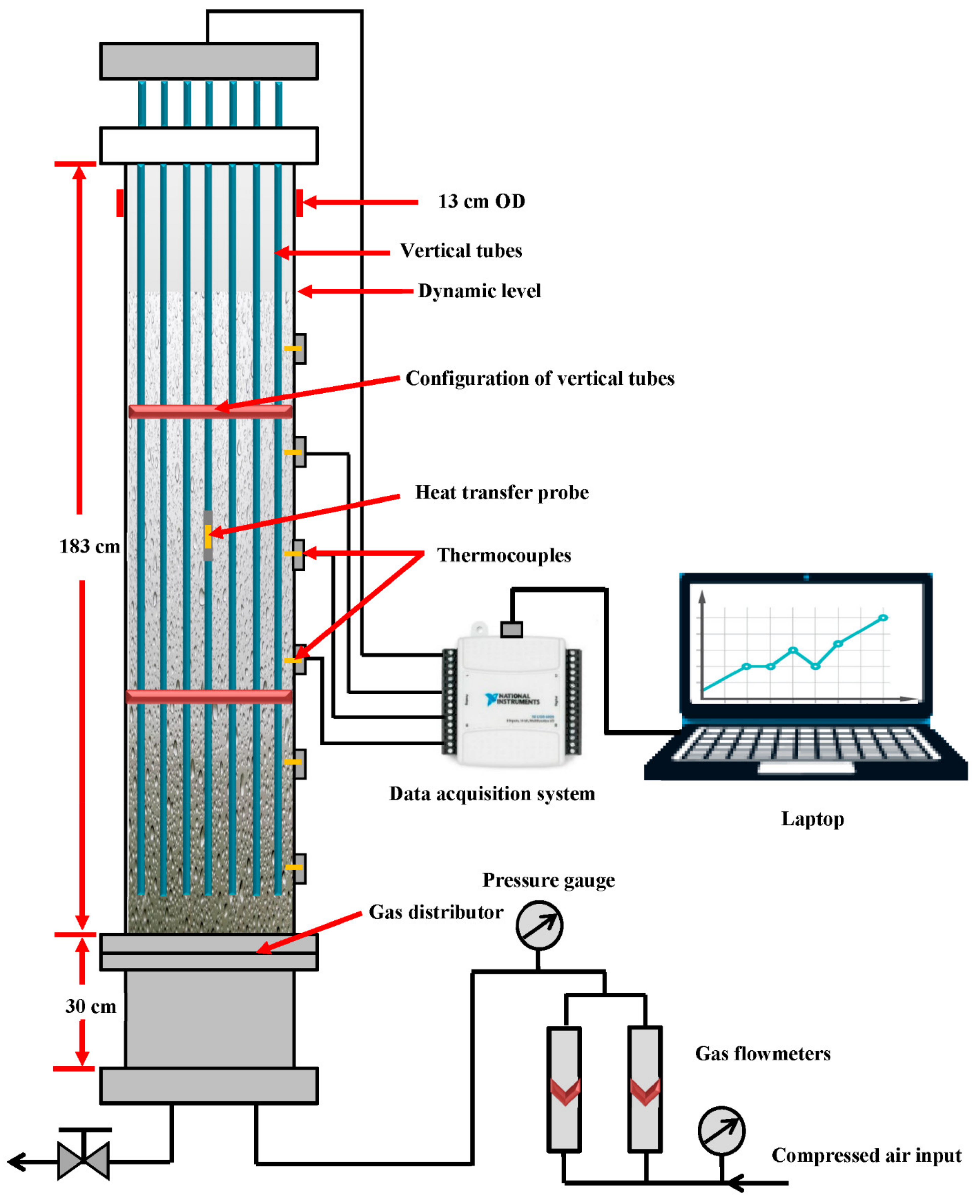
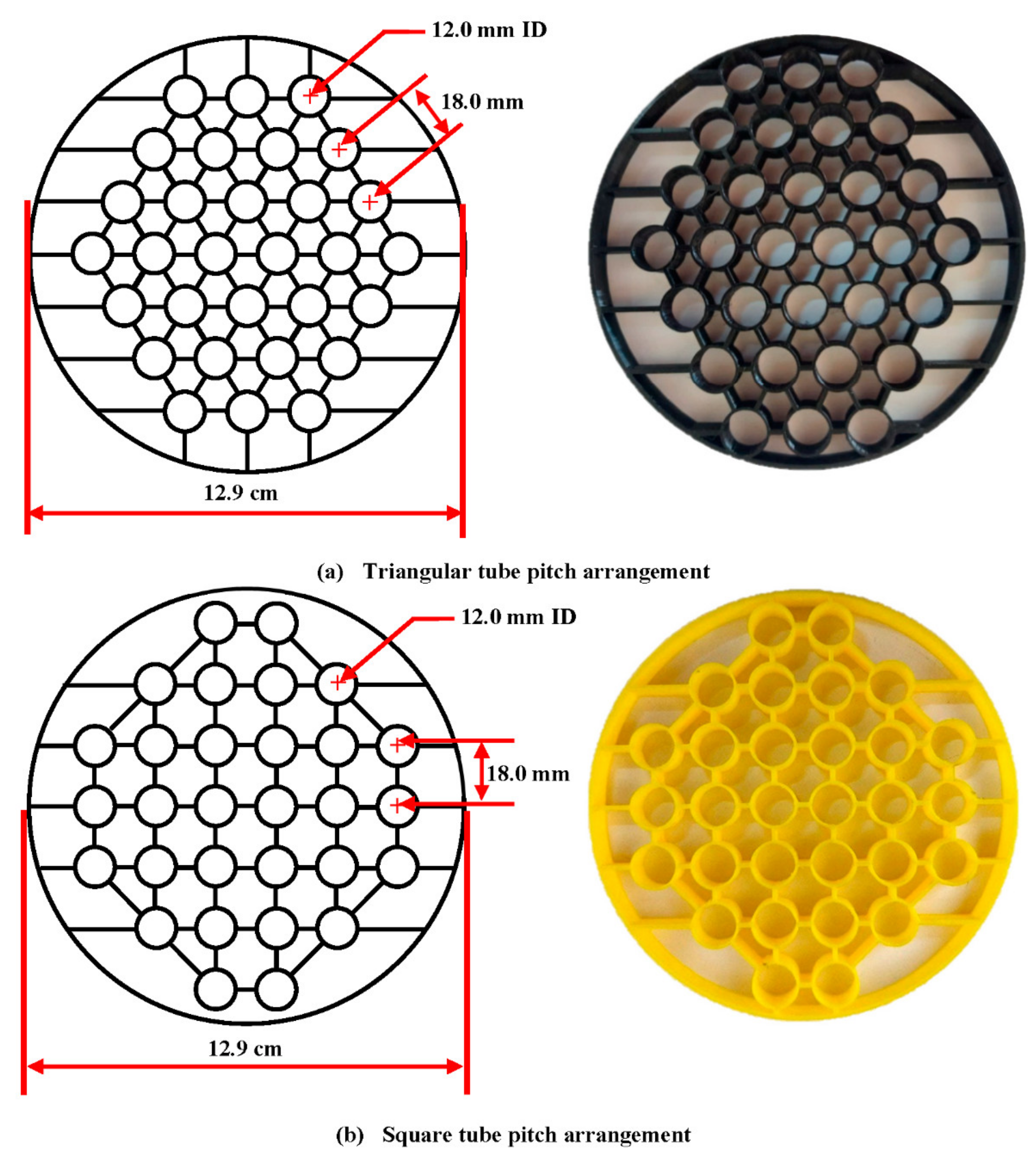
2.1. Experimental Bubble Column Setup

The experiments of this study were carried out in a Plexiglas bubble column with a 0.13 m internal diameter and a height of 1.83 m, as shown schematically in Figure 1. Industrially, a bundle of cooling tubes is installed vertically inside the reactor to control the Fischer-Tropsch reactor’s temperature and remove the heat generated. Therefore, a bundle of tubes was designed, manufactured, and installed vertically in the bubble column reactor to mimic the industrial Fischer-Tropsch’s reactor. This bundle was designed to cover 25% of the cross-sectional area of the bubble column reactor to simulate the industrial bubble column used in the FT process. This tube bundle consisted of 30 stainless steel tubes 12 mm in diameter and 190 cm high. A stepper motor was used to easily raise and lower the tube bundle within the bubble column reactor, thus allowing the LHTC measurement at any axial location along with the column’s height. Two different designs of tube arrangements (i.e., triangular and square tube pitch arrangements) were designed and implemented to study, for the first time, the impact of these arrangements on the instantaneous LHTC in a mimicked FT bubble column reactor. These tube arrangements were plotted by the SOLIDWORKS program first, and then they were printed by a 3D printer (Ender-3 Pro 3D Printer, Creality3D, Shenzhen, China, 518109). Figure 2 exhibits the shapes and dimensions of these tube arrangements. The bottom of the bubble column is equipped with a perforated plate gas distributor. This gas distributor has 121 holes with a size of one mm. These holes were structured in a triangular geometry with a free overall area of 1.09 percent. In all experiments, the bubble column was operated in semi-batch mode with air and water as the working fluids. The water was fed into the bubble column before starting the experiment, while the compressed air was continuously supplied to the column through the distributor. The compressed air feed to the column was first regulated and then purified using a pressure regulator and air filter and then passed to two calibrated flowmeters to control the superficial gas velocity. During this study, these flowmeters were combined in a parallel configuration to measure the LHTC in various gas volumetric flow rates.
The experiments were carried out under a wide range of superficial gas velocities (0.05–0.45 m/s) at different radial and axial positions (35 and 65 cm height).

2.2. Advanced Heat Transfer Technique

An advanced heat transfer technique was utilized to quantify the instantaneous and local heat flux and heat transfer coefficient in the studied bubble column reactor. This technique consists of a heat transfer probe, thermocouples, amplifier, DC power supply, and data acquisition system. The main component of this technique is the heat transfer probe. The heat transfer probe consists of a 10 cm length of cylindrical brass with a 12 mm outside diameter, which was machined in a way to insert a heater cartridge (Heatron, Inc. Leavenworth, KS, USA, US005136143A). Two pieces of Teflon with the same diameter (12 mm) were fixed at the top and bottom of cylindrical brass to prevent heat loss from the top and bottom sides. In addition, a PHFS heat flux sensor was attached to the outside of the cylindrical brass by using thermal conductive glue. In this study, the heat transfer probe was designed and developed to attach to any tube of the bundle of tubes. Hence, the heat transfer probe can be moved horizontally and vertically through the bubble column (i.e., at any radial and axial locations). Figure 3 exhibits the schematic and photo of the heat transfer probe attached to one tube of the bundle. Table 1 displays the specification of the PHFS heat flux sensor used in this study. The PHFS heat flux sensor has two features; firstly, it can measure the heat flux which passes through the sensor, and, secondly, it can measure the surface temperature when attached to anything. The bulk temperature of the bubble column was measured by three K-type thermocouples, which were inserted into the column in three positions with a distance of 10 cm between each one. It is worth noting that the thermocouples’ calibration was carried out before taking any measurements to improve the accuracy of the data, typically a maximum of +/−2.2 °C or +/−0.75%). Therefore, using the heat flux data and the thermocouples of the bulk data, the LHTC was calculated according to the cooling law of Newton.
q = h A T s T b
h = q / A T s T b = q T s T b
where h :   the LHTC between the heat flux sensor and the bulk of the bubble column, W/m2. °C; q : the heat flux passed through the heat flux sensor, W/m2; T s : surface temperature, °C; T b : bulk temperature, °C.
In this study, the cartridge heater was supplied with electric power using a DC power supply (HY 5003 model manufactured by RSR electronics Inc., Rahway, NJ, USA) with a 0–50 V voltage range. During the experiments, the output of the PHFS heat flux sensor was a microvolt that is linearly proportional to the heat flux absorbed by the sensor. Therefore, an amplifier (JH-Technology, Inc., model JH5200) was used to amplify the received signals before sending them to the data acquisition instrument (DAQ, model NI USB—6008). The experimental data were recorded for 300 s at a rate of 50 Hz. The acquired output voltage signals, surface, and bulk temperatures were processed by a developed in-house MATLAB code to obtain the local instantaneous and average heat transfer coefficient. Therefore, from the obtained heat flux, the surface temperature of the probe and bulk temperatures, and the local instantaneous and average of the heat transfer coefficient, were calculated as follows:
h i = q i T s i T b i
h a v . = 1 N i = 1 N q i T s i T b i
where h i :   instantaneous local heat transfer coefficient, W/m2. °C; q i : instantaneous heat flux, W/m2; T s i : instantaneous surface temperature, °C; T b i : instantaneous bulk temperature, °C; h a v . : average heat transfer coefficient, W/m2. °C; N : total number of acquired data.
In this study, each experiment measuring the LHTC was replicated three times during the experimental work. Then, only the average of these three repetitions was calculated and plotted in the result section to inspect the reliability of every experiment.

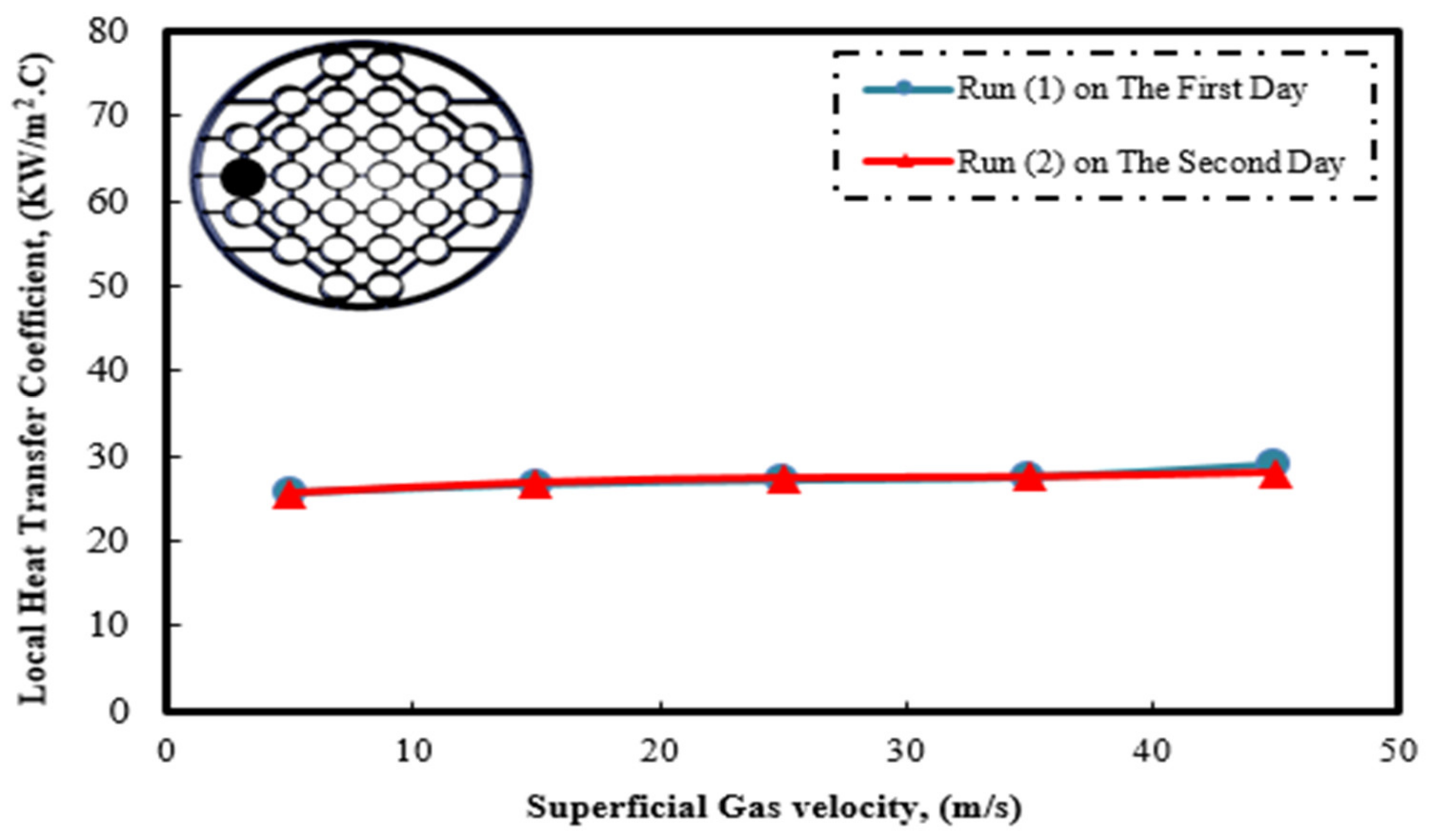
2.3. The Accuracy and Reproducibility of the Measurements

The reproducibility of the experiments is one of the most important factors to consider before taking any measurements. Therefore, the reproducibility of measurements was conducted before conducting the experiments to check the uncertainty and reliability of the acquired data. The LHTC in the wall region and the axial level of 65 cm of the bubble column were measured two times at constant operating conditions for reproducibility assessment. The replication of measurements was made on two successive days, as the LHTC was measured for a broad range of the operating gas velocities on the first day, and then the LHTC was measured again under the same operating conditions. Figure 4 displays the reproducibility assessment results for heat transfer coefficient measurements under a wide range of superficial gas velocities. It can be observed from Figure 4 that the measurements of the LHTC on the first day are in complete agreement with the measurements of the second day. For instance, it was found that the average relative and absolute difference between the first- and second-day measurements is 1.05%. These results of this analysis prove the reliability of the heat transfer technique for measuring the LHTC under a wide range of operating conditions with high accuracy. It is important to mention that the LHTC measurements, under specified conditions, were replicated three times while collecting data. Hence, the average of these values was present in the results section to ensure data reliability with very few deviations. As a result, the error bars may be distinguished in most of the figures.

3. Results and Discussion

In this section, the impact of a bundle of vertical tubes and their arrangement (square and triangular pitch tube arrangement) on the instantaneous and LHTC is examined. The heat transfer coefficient measurements were conducted under a range of superficial gas velocities (0.05–0.45 m/s) and at different radial and axial locations (35 and 65 cm height) to draw a clear conclusion about the impact of the presence of the bundle of the heat exchanging tubes and their arrangements. The impact of the tube arrangements, gas velocity, radial positions, and axial locations will be presented and discussed in the coming sections.

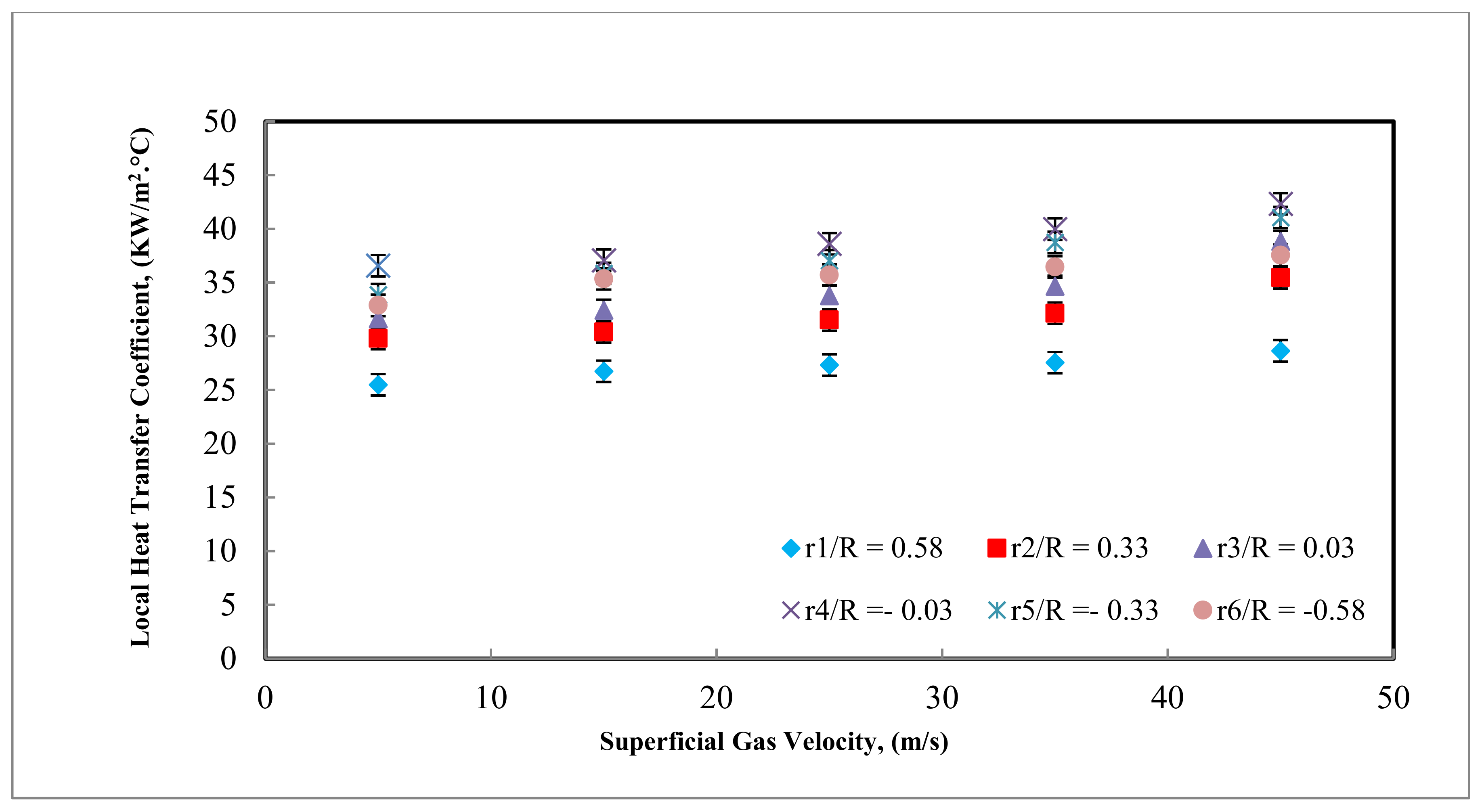
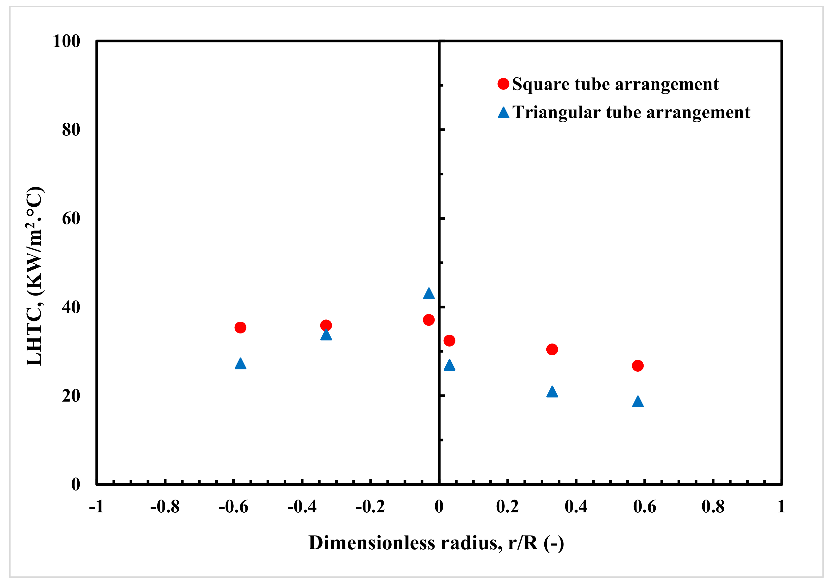
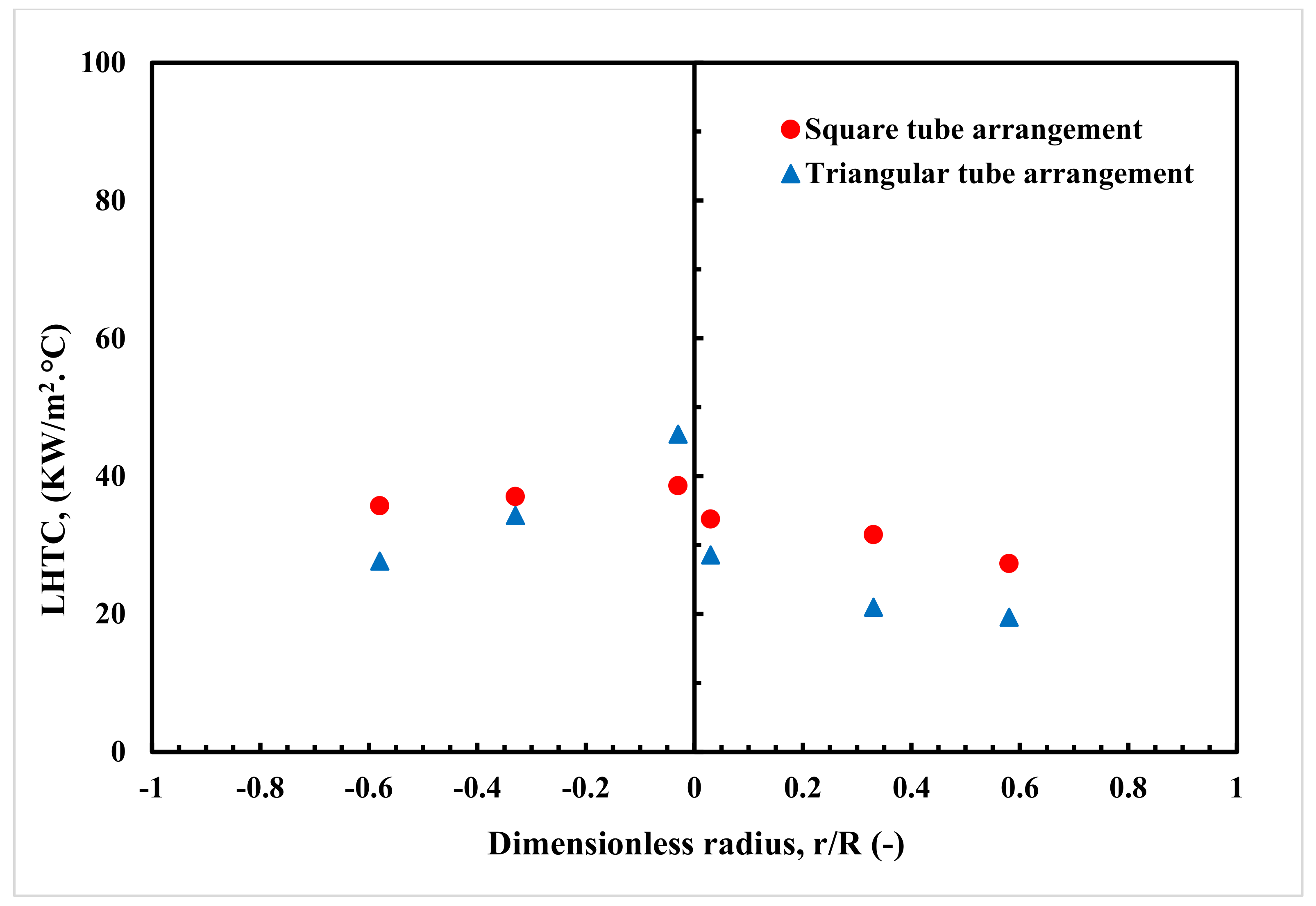
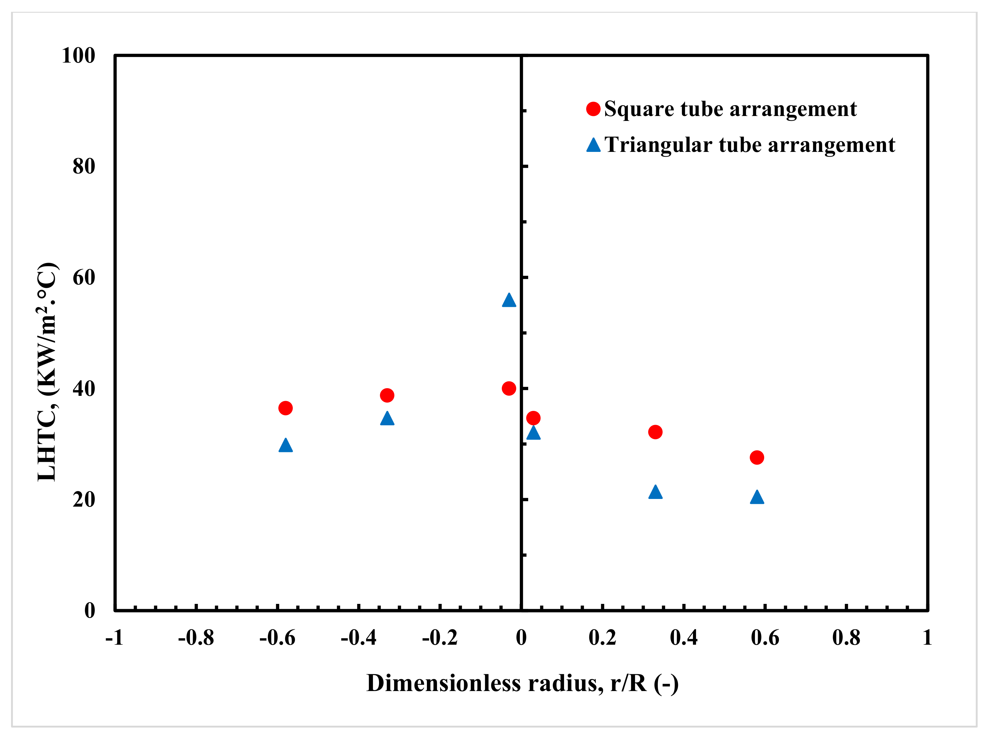
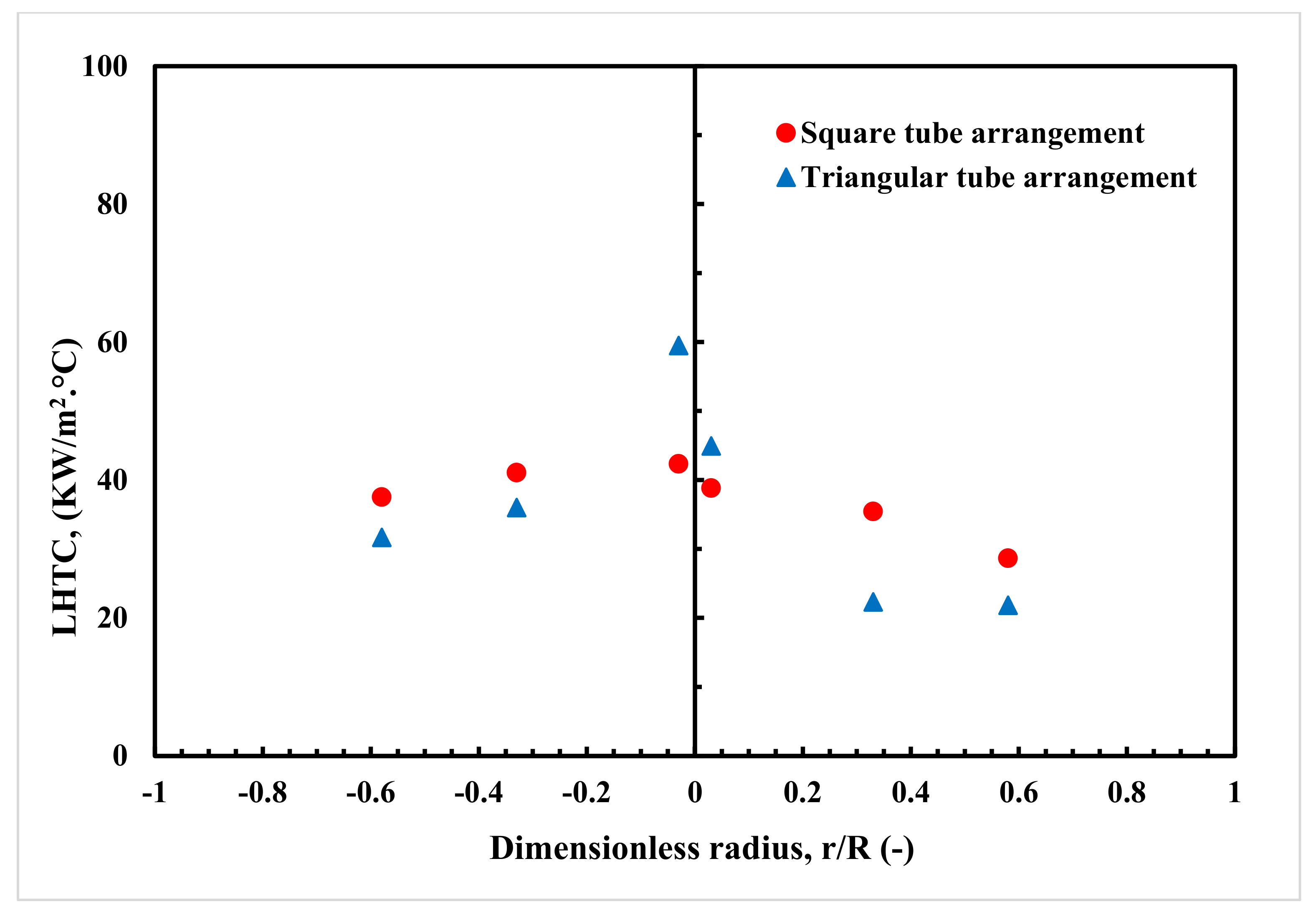
3.1. The Effect of the Tube’s Arrangements on the Local Heat Transfer Coefficient under Different Superficial Gas Velocity

Figure 5 and Figure 6 demonstrate the impact of the tube arrangement designs (i.e., triangular and square pitch tube arrangements) on the LHTC profile under various gas velocities for all of the radial positions. It can be seen from these figures that the magnitude of the LHTC increases as the superficial gas velocity increases for all of the radial positions of the bubble column. Moreover, Figure 7, Figure 8, Figure 9, Figure 10 and Figure 11 illustrate the impact of the tubes’ arrangements at different radial positions. These figures illustrate that the increase in the heat transfer coefficient at the center of the column was more significant than at the wall region for both tube arrangements. Interestingly, it can be seen from these figures that the square pitch tube arrangement gives higher heat transfer coefficient values for all of the radial positions than the triangular pitch tube arrangement except at a dimensionless radius of r/R = −0.03. For instance, under the operating conditions of the gas velocity of 0.45 m/s, the percentage of the increase for the LHTC values at all of the radial positions, except the center for the square tube arrangement, was 30% compared to the triangular tube arrangement. Additionally, the square tube arrangement offers radially uniform heat transfer coefficient profiles for all of the used gas velocities, while the triangular offers a non-uniform profile. The uniformity of the heat transfer coefficient distribution seen in the square tube arrangement is an indication that when the column is equipped with a bundle of tubes, it causes insignificant bulk liquid circulation compared to the parabolic profiles obtained in a bubble column without tubes. This interesting finding will open the doors for using the heat transfer technique to distinguish the flow regimes of these reactors and will create opportunities for future research.
Moreover, one can notice that the heat transfer coefficient values on the left side of the column are higher than on the right side of the column, and this observation is evident in the triangular tube arrangement, which is a sign of asymmetric distribution. These distinct asymmetric local heat transfer coefficient profiles were obtained when the triangular pitch tube arrangement was employed with the studied bubble column. This asymmetric profile can be demonstrated by the high values of the local heat transfer coefficient on one side of the column and low values on the other, as shown in the figures. For example, at a gas velocity of 0.45 m/s, the percentage difference of the LHTC at dimensionless radius points, r/R = ±0.6 and ±0.9, are 100% and 180%, respectively. The observed distinct asymmetric heat transfer coefficient profiles in the bubble column with the triangular tube arrangement can be attributed to the design of this triangular tube arrangement where this design creates more clearance and nonsymmetrical spaces between the bundle of tubes and the wall of the bubble column, as shown in Figure 2a. This clearance and the nonsymmetrical spaces induce a channeling gas flow in most of the upward gas flow on one side and a reverse flow of liquid on the other side. Hence, this design of the triangular tube arrangement alters the liquid circulation inside the column and causes more gas bubbles to move toward the clearance between the bundle and the wall, where less resistance to the flow exists, as observed visually. Such observation confirms the findings and the analysis previously obtained by Al-Mesfer et al. [11], who scanned a bubble column (15.24 cm in diameter) equipped with vertical internals organized in a triangular layout by advanced CT scan under a wide range of operating gas velocity. Their CT scan images of the cross-sectional gas holdup distribution of the bubble column revealed a non-uniform gas holdup distribution when a triangular tube arrangement was used for all of the examined gas velocities. According to their CT images, it was found that most of the gas concentrated on the left side, and there was a shortage of gas on another side. This explains why heat transfer coefficient values on the left side are higher than on the other side. For example, it is well known that the gas phase drives the liquid circulation in the bubble column, therefore increasing the gas holdup on one side, causing an increase in the axial liquid velocity on this side and, consequently, increasing the heat transfer coefficient on this side.
From an economic and industrial point of view, high values and uniform heat transfer coefficient distributions are desired to achieve high performance for bubble and slurry bubble columns for the Fischer-Tropsch process. This is due to the high heat transfer rate from the reactants to the cooling tubes, and, consequently, there will be no hot spot within the used catalyst of this reactor or easy control of the operating temperature of this reaction. Therefore, according to the obtained results on the impact of tube arrangements on the LHTC, a square tube arrangement is advised to be used industrially.

3.2. Quantification of the Effect of Tube Arrangements on the LHTC at Different Axial Locations

The impact of axial height on the LHTC was addressed and quantified by measuring the heat transfer coefficient at two different axial heights (H/D = 2.7 and H/D = 5) for all of the studied gas velocities in the bubble column having vertical tubes organized in a triangular tube arrangement. Figure 12, Figure 13, Figure 14, Figure 15 and Figure 16 demonstrate the influence of the axial height on the heat transfer coefficient when a triangular tube arrangement was used for a broad range of gas flowrates representing the bubbly, transition, and churn turbulent flow regimes. It can be noticed that from these figures, the LHTC on the left side of the column increased when increasing the operating gas velocities while remaining almost constant on the right side of the column. Such results were not reported before in the literature because all of the previous investigations measured the heat transfer coefficient and hydrodynamic parameters on one side of the column by assuming symmetrical fluid behavior in the bubble column. However, such an assumption does not stand for a bubble column having vertical tubes. Therefore, one must be cautious when measuring heat transfer, hydrodynamic parameters, and mass transfer in bubble columns due to nonsymmetrical behavior when this column is equipped densely with a bundle of vertical tubes. Also, these figures reveal that axial height significantly impacts the LHTC on the left side, where higher values were obtained in the fully developed flow region (H/D = 5) compared to the gas distributor region (not developed region, H/D = 2.7) for all of the studied gas velocities. For instance, the percentage increase of the heat transfer coefficients at the axial level of H/D = 5 and under a superficial gas velocity of 0.45 m/s was 29.7% compared to the axial level of H/D = 2.7.
Conversely, the LHTC on the right side decreased by 24.6% at the axial level of H/D = 5 and under the superficial gas velocity of 0.45 m/s compared to the axial level of H/D = 2.7. The results also give further evidence that using a triangular tube arrangement causes non-uniform heat transfer coefficient distributions even with different axial heights, which significantly impacts the thermal performance of such a reactor. Furthermore, the highest values of the local heat transfer coefficient were achieved at the center region of the column (r/R = −0.03), particularly at high superficial gas velocities (i.e., churn turbulent regime, 0.35 and 0.45 m/s). This can be attributed to the smaller free area to flow (i.e., space between the tubes) at the center region when the column is equipped with vertical tubes arranged in a triangular arrangement. This triangular arrangement provides a smaller compartment (free area to flow), which causes the axial liquid velocity to increase in this compartment and, accordingly, enhances the heat transfer coefficient. Interestingly the current heat transfer technique was able to capture the maldistribution (nonuniformity) of the heat transfer coefficient when the triangular tube arrangement was used because the heat transfer coefficient correlates strongly with the local gas holdup and, consequently, the liquid velocity profiles. Accordingly, the high heat transfer values on the left side are signs of a high local gas holdup and represent ascending liquid. In contrast, regions with a low LHTC represent descending liquid. Therefore, the heat transfer coefficient profiles indirectly indicate the flow behavior in terms of gas holdup and liquid velocity profiles.
As a comparison with the existing data in the literature, Figure 17 demonstrates the experimental results of the LHTC for different tube arrangements with the previous studies. The LHTC was assessed in the center region with a wide range of superficial gas velocities. Moreover, the experimental results obtained for the LHTC increase uniformly with increasing the superficial gas velocity, showing the same trends as Rahman’s [37]. It is worth noting that the LHTC values from the previous study are lower than the values from our study due to several aspects, including the column diameter, the free cross-sectional area, different tube configurations, the height of the heat transfer probe from the distributor, and the variations in the dimensions for the cartridge heater, in both cases.Therefore, this study improves the impact of the tubes’ configuration on the local heat transfer coefficient and the reactor performance.

4. Conclusions

In this work, we used a sophisticated heat transfer technique to study the local heat transfer coefficients in a bubble column occupied with a bundle of tubes. Additionally, the impact of using two designs of tube arrangements on the heat transfer coefficient was examined under a range of gas velocities (0.05–0.45 m/s). Furthermore, the influence of the axial height on heat transfer coefficients was also investigated. The key results are outlined as follows:
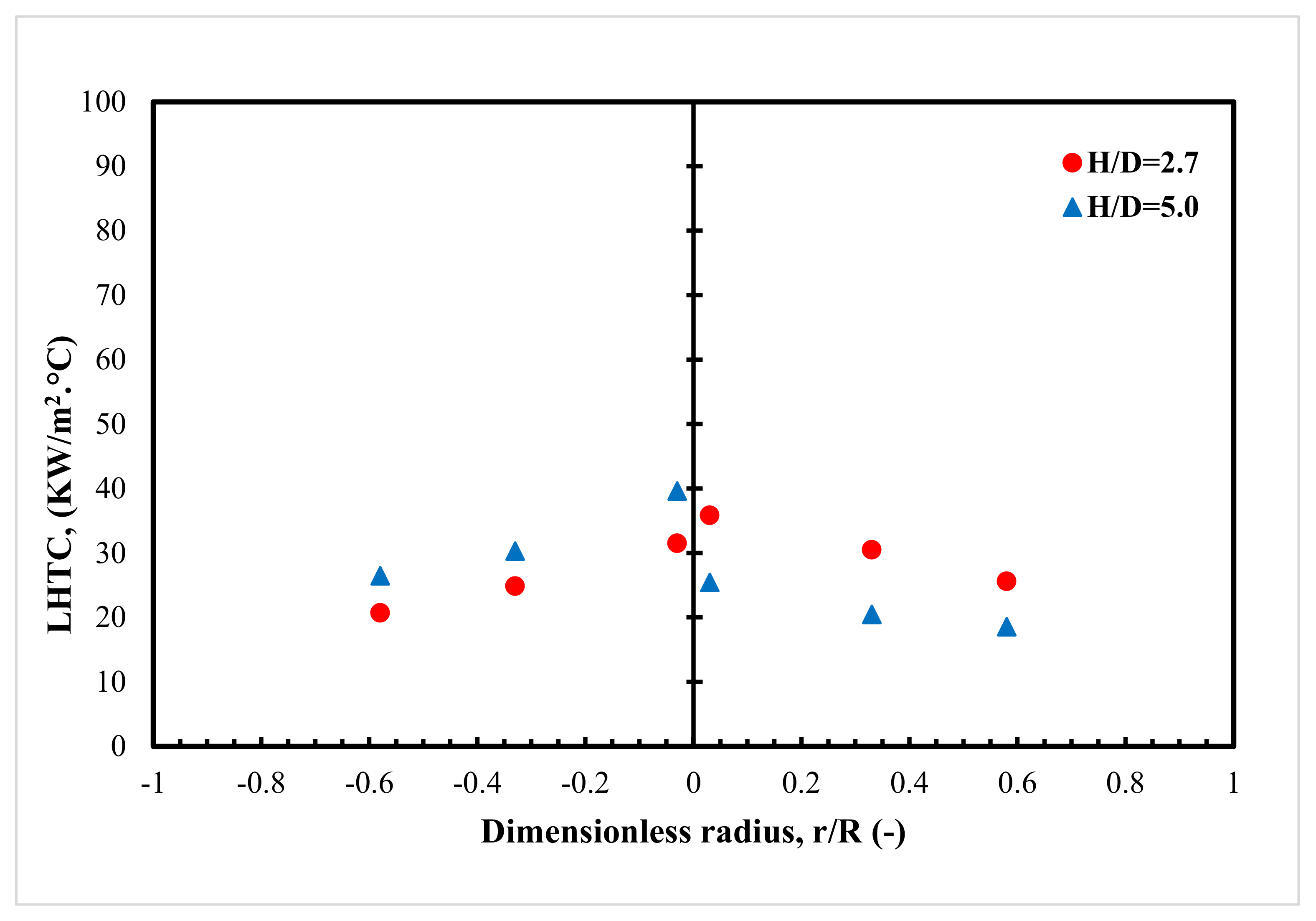
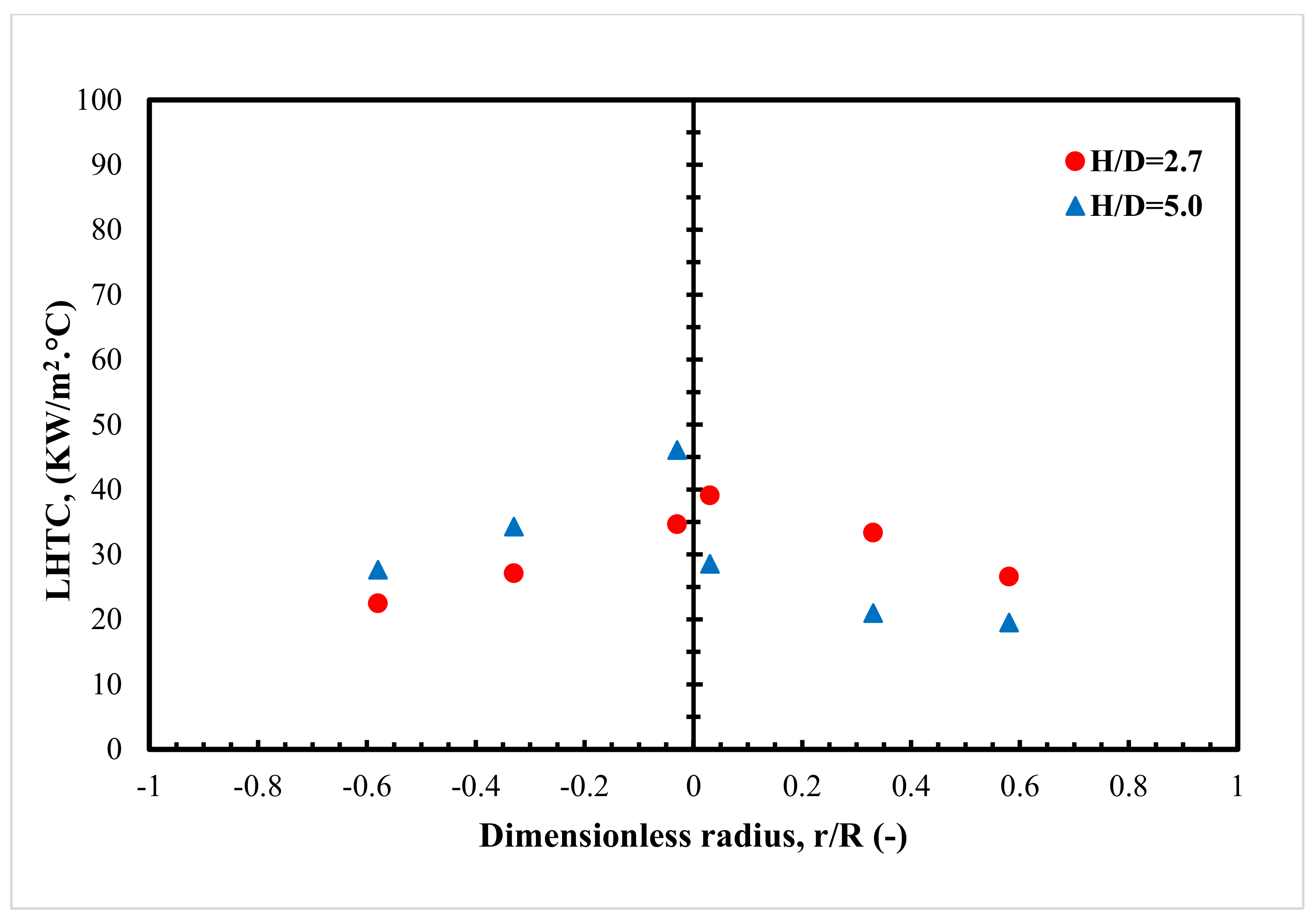
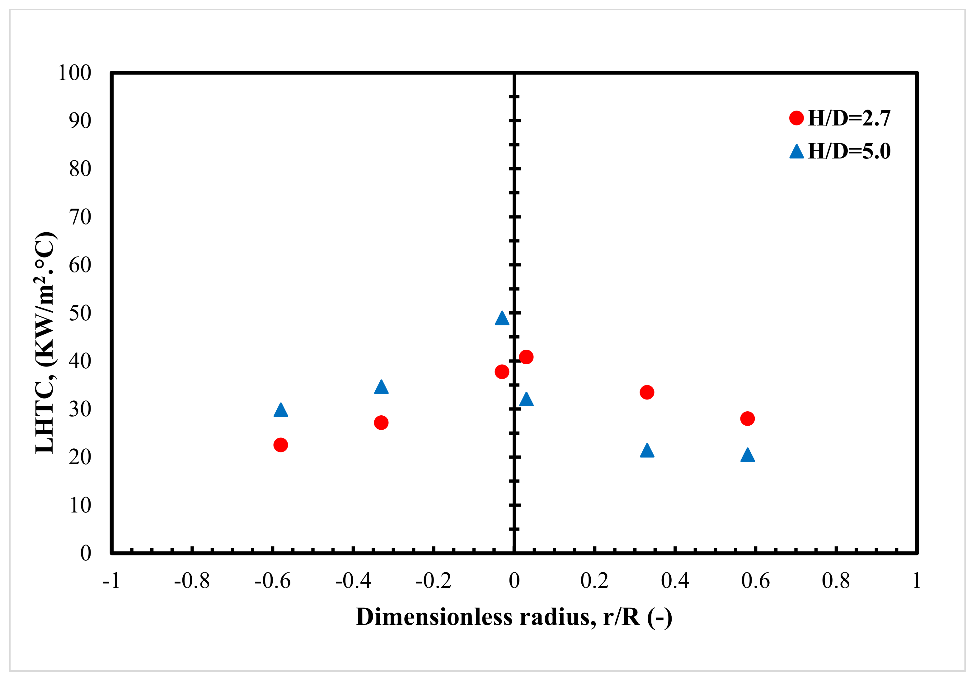
  • The LHTC increases as the gas velocity increases, and higher heat transfer values are obtained in the center of the column, despite this column being equipped densely with a bundle of tubes.
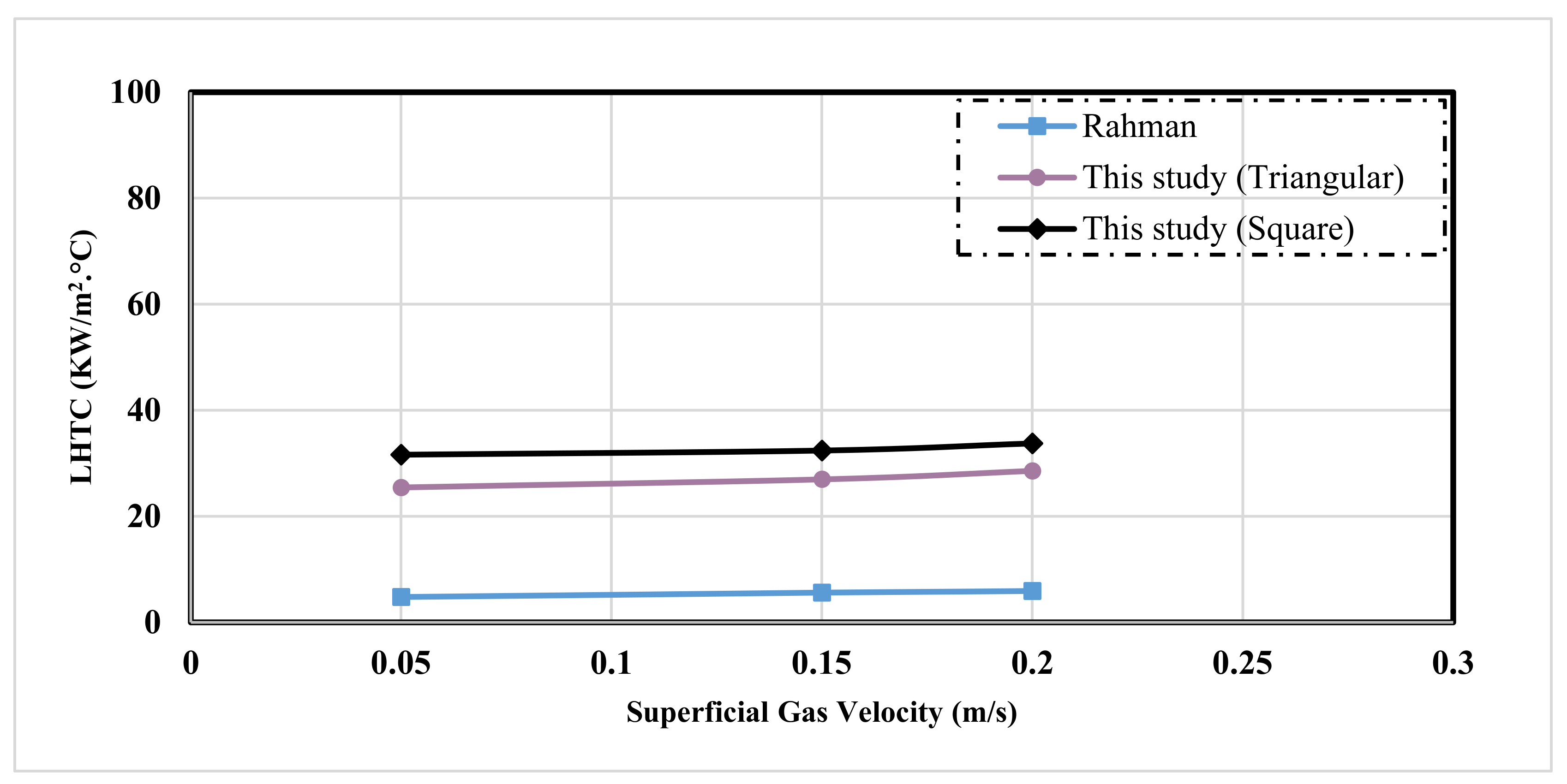
  • The shape of the heat transfer coefficient profiles is significantly influenced by the tubes’ arrangement design. For example, steeper heat transfer coefficient profiles were achieved when the triangular tube pitch arrangement was used.
  • The square tube pitch arrangement provides uniform heat transfer profiles, while the non-uniform profiles are obtained with a triangular tube arrangement for all of the studied gas velocities. For example, under operating conditions of a 0.45 m/s gas velocity, the percentage of the increase for the LHTC values at all of the radial positions, unlike the center for the square tube arrangement, was 30%, particularly in comparison to the triangular tube configuration.
  • The heat transfer coefficients are significantly affected by the axial height when the heat transfer coefficient is measured between the gas distributor region and the fully developed flow region. For all of the gas velocities studied, higher values were obtained in the fully developed flow region (H/D = 5) compared to the gas distributor region (H/D = 2.7). For instance, the percentage increase in the heat transfer coefficients at the axial level of H/D = 5 and superficial gas velocity of 0.45 m/s was 29.7% if compared to the axial level of H/D = 2.7.

5. Recommendation

The following recommendations for future research are presented in order to get a comprehensive understanding of the heat transfer in a bubble column reactor:
  • All of the correlations available for estimating the heat transfer coefficient of a bubble column equipped with a bundle of tubes were developed utilizing data from a bubble column without a bundle of tubes. As a result, it recommended developing a mathematical model to accurately predict heat transfer coefficients in bubble columns densely occupied with bundle tubes.
  • In this work, all of the heat transfer coefficients were measured under atmospheric pressure, and ambient temperature, and the industrial Fischer-Tropsch reactor operated at high pressure and temperature. Therefore, it is recommended to quantify heat transfer coefficients in mimicked FT operating conditions.

Author Contributions

Conceptualization, A.J.S., and A.A.A.; methodology, A.N.A.; software, A.J.S.; validation, A.N.A., A.A.A., and H.S.M.; formal analysis, A.J.S.; investigation, A.N.A.; resources, H.S.M.; data curation, A.N.A.; writing—original draft preparation, A.J.S.; writing—review and editing, A.A.A.; visualization, H.S.M.; supervision, A.A.A.; project administration, A.J.S.; funding acquisition, H.S.M. All authors have read and agreed to the published version of the manuscript.

Funding

This research received no external funding.

Institutional Review Board Statement

Not applicable.

Informed Consent Statement

Not applicable.

Data Availability Statement

Not applicable.

Acknowledgments

The authors would like to thank the Missouri University of Science and Technology, the University of Technology-Iraq, and the Al Mustaqbal University College for financial support for this work. In addition, the authors would like to acknowledge the graduate student’s effort (Zahraa W. Hasan) in implementing the reviewer’s and the editor’s comments.

Conflicts of Interest

The authors declare that they have no known competing financial interests or personal relationships that could have appeared to influence the work reported in this paper.

Nomenclature

AA probe heat transfer area, m2
HThe distance between the tubes and the gas distributor
H/DAxial distance above the gas distributor, m
h   LHTC between the heat flux sensor and the bulk of bubble column, W/m2. °C
q The heat flux passed through the heat flux sensor, W/m2
T s   Surface temperature, °C
T b Bulk temperature, °C
h i   Instantaneous local heat transfer coefficient, W/m2. °C
q i   Instantaneous heat flux, W/m2
T s i   Instantaneous surface temperature, °C
T b i   Instantaneous bulk temperature, °C
h a v .   Average heat transfer coefficient, W/m2. °C
N   Total number of acquired data
rRadial location in the column, m
RRadius of column, m

References

  1. Dong, K.; Jiang, H.; Sun, R.; Dong, X. Driving forces and mitigation potential of global CO2 emissions from 1980 through 2030: Evidence from countries with different income levels. Sci. Total Environ. 2019, 649, 335–343. [Google Scholar] [CrossRef] [PubMed]
  2. Krishna, R. A Scale-Up Strategy for a Commercial Scale Bubble Column Slurry Reactor for Fischer-Tropsch Synthesis. Oil Gas Sci. Technol. 2000, 55, 359–393. [Google Scholar] [CrossRef] [Green Version]
  3. Saeidi, S.; Nikoo, M.K.; Mirvakili, A.; Bahrani, S.; Amin, N.A.S.; Rahimpour, M.R. Recent advances in reactors for low-temperature Fischer-Tropsch synthesis: Process intensification perspective. Rev. Chem. Eng. 2015, 31, 209–238. [Google Scholar] [CrossRef]
  4. Boyer, C.; Gazarian, J.; Lecocq, V.; Maury, S.; Forret, A.; Schweitzer, J.-M.; Souchon, V. Development of the Fischer-Tropsch Process: From the Reaction Concept to the Process Book. Oil Gas Sci. Technol.–Rev. d’IFP Energies Nouv. 2016, 71, 44. [Google Scholar] [CrossRef] [Green Version]
  5. Gholami, Z.; Tišler, Z.; Rubáš, V. Recent advances in Fischer-Tropsch synthesis using cobalt-based catalysts: A review on supports, promoters, and reactors. Catal. Rev.-Sci. Eng. 2021, 63, 512–595. [Google Scholar] [CrossRef]
  6. Calvo, W.A.P.; Hamada, M.M.; Sprenger, F.E.; Vasquez, P.A.S.; Rela, P.R.; Martins, J.F.T.; De Matos Pereira, J.C.S.; Omi, N.; De Mesquita, C.H. Gamma-ray computed tomography SCANNERS for applications in multiphase system columns. Chem. Eng. Sci. 2009, 54, 129–133. [Google Scholar] [CrossRef]
  7. Hulet, C.; Clement, P.; Dromard, N.; Hulet, C.; Clement, P.; Tochon, P.; Schweich, D.; Anfray, J. Literature Review on Heat Transfer in Two- and Three-Phase Bubble Columns. Int. J. Chem. React. Eng. 2009, 7, hal-01933194. [Google Scholar] [CrossRef]
  8. Rahimpour, M.R.; Jokar, S.; Jamshidnejad, Z. A novel slurry bubble column membrane reactor concept for Fischer-Tropsch synthesis in GTL technology. Chem. Eng. Res. Des. 2012, 90, 383–396. [Google Scholar] [CrossRef]
  9. Guan, X.; Gao, Y.; Tian, Z.; Wang, L.; Cheng, Y.; Li, X. Hydrodynamics in bubble columns with pin-fin tube internals. Chem. Eng. Res. Des. 2015, 102, 196–206. [Google Scholar] [CrossRef]
  10. Jasim, A.A.; Sultan, A.J.; Al-Dahhan, M.H. Impact of heat exchanging internals configurations on the gas holdup and bubble properties in a bubble column. Int. J. Multiph. Flow 2019, 112, 63–82. [Google Scholar] [CrossRef]
  11. Al Mesfer, M.K.; Sultan, A.J.; Al-Dahhan, M. Impacts of dense heat exchanging internals on gas holdup cross-sectional distributions and profiles of bubble column using gamma ray Computed Tomography (CT) for FT synthesis. Chem. Eng. J. 2016, 300, 317–333. [Google Scholar] [CrossRef]
  12. Sultan, A.J.; Sabri, L.S.; Al-Dahhan, M.H. Influence of the size of heat exchanging internals on the gas holdup distribution in a bubble column using gamma-ray computed tomography. Chem. Eng. Sci. 2018, 186, 1–25. [Google Scholar] [CrossRef]
  13. Meurer, A.; Kern, J. Fischer-Tropsch Synthesis as the Key for Decentralized Sustainable Kerosene Production. Energies 2021, 14, 1836. [Google Scholar] [CrossRef]
  14. Konarova, M.; Aslam, W.; Perkins, G. Fischer-Tropsch synthesis to hydrocarbon biofuels: Present status and challenges involved. In Hydrocarbon Biorefinery; Elsevier: Amsterdam, The Netherlands, 2022; pp. 77–96. [Google Scholar] [CrossRef]
  15. Al Mesfer, M.K.; Sultan, A.J.; Al-Dahhan, M. Study the effect of dense internals on the liquid velocity field and turbulent parameters in bubble column for Fischer-Tropsch (FT) synthesis by using Radioactive Particle Tracking (RPT) technique. Chem. Eng. Sci. 2017, 161, 228–248. [Google Scholar] [CrossRef]
  16. Jasim, A.A.; Sultan, A.J.; Al-Dahhan, M.H. Influence of heat-exchanging tubes diameter on the gas holdup and bubble dynamics in a bubble column. Fuel 2019, 236, 63–82. [Google Scholar] [CrossRef]
  17. Sultan, A.J.; Sabri, L.S.; Al-Dahhan, M. Impact of heat-exchanging tube configurations on the gas holdup distribution in bubble columns using gamma-ray computed tomography. Int. J. Multiph. Flow 2018, 106, 202–219. [Google Scholar] [CrossRef]
  18. Sultan, A.J.; Sabri, L.S.; Al-Dahhan, M.H. Investigating the influence of the configuration of the bundle of heat exchanging tubes and column size on the gas holdup distributions in bubble columns via gamma-ray computed tomography. Exp. Therm. Fluid Sci. 2018, 98, 68–85. [Google Scholar] [CrossRef]
  19. Chen, P.; Sanyal, J.; Duduković, M. Numerical simulation of bubble columns flows: Effect of different breakup and coalescence closures. Chem. Eng. Sci. 2005, 60, 1085–1101. [Google Scholar] [CrossRef]
  20. Chen, P.; Gupta, P.; Dudukovic, M.; Toseland, B. Hydrodynamics of slurry bubble column during dimethyl ether (DME) synthesis: Gas-liquid recirculation model and radioactive tracer studies. Chem. Eng. Sci. 2006, 61, 6553–6570. [Google Scholar] [CrossRef]
  21. Youssef, A.A.; Hamed, M.E.; Grimes, J.T.; Al-Dahhan, M.H.; Duduković, M.P. Hydrodynamics of pilot-scale bubble columns: Effect of Internals. Ind. Eng. Chem. Res. 2013, 52, 43–55. [Google Scholar] [CrossRef]
  22. Rollbusch, P.; Becker, M.; Ludwig, M.; Bieberle, A.; Grünewald, M.; Hampel, U.; Franke, R. Experimental investigation of the influence of column scale, gas density and liquid properties on gas holdup in bubble columns. Int. J. Multiph. Flow 2015, 75, 88–106. [Google Scholar] [CrossRef]
  23. Kagumba, M.; Al-Dahhan, M.H. Impact of internals size and configuration on bubble dynamics in bubble columns for alternative clean fuels production. Ind. Eng. Chem. Res. 2015, 54, 1359–1372. [Google Scholar] [CrossRef]
  24. Pourtousi, M.; Ganesan, P.; Sahu, J.N. Effect of bubble diameter size on prediction of flow pattern in Euler–Euler simulation of homogeneous bubble column regime. Measurement 2015, 76, 255–270. [Google Scholar] [CrossRef]
  25. Besagni, G.; Inzoli, F. Influence of internals on counter-current bubble column hydrodynamics: Holdup, flow regime transition and local flow properties. Chem. Eng. Sci. 2016, 145, 162–180. [Google Scholar] [CrossRef] [Green Version]
  26. Roy, S. Radiotracer and particle tracking methods, modeling and scale-up. AIChE J. 2017, 63, 314–326. [Google Scholar] [CrossRef]
  27. Kalaga, D.V.; Bhusare, V.; Pant, H.; Joshi, J.B.; Roy, S. Impact of dense internals on fluid dynamic parameters in bubble Column. Int. J. Chem. React. Eng. 2018, 16, 105743066. [Google Scholar] [CrossRef]
  28. Sultan, A.J.; Sabri, L.S.; Shao, J.; Al-Dahhan, M.H. Corrigendum to: Overcoming the gamma-ray computed tomography data processing pitfalls for bubble column equipped with vertical internal tubes. Can. J. Chem. Eng. 2018, 96, 2206–2226. [Google Scholar] [CrossRef]
  29. Chen, J.; Li, F.; Degaleesan, S.; Gupta, P.; Al-Dahhan, M.H.; Dudukovic, M.P.; Toseland, B.A. Fluid dynamic parameters in bubble columns with internals. Chem. Eng. Sci. 1999, 54, 2187–2197. [Google Scholar] [CrossRef]
  30. Larachi, F.; Desvigne, D.; Donnat, L.; Schweich, D. Simulating the effects of liquid circulation in bubble columns with internals. Chem. Eng. Sci. 2006, 61, 4195–4206. [Google Scholar] [CrossRef]
  31. Jhawar, A.K. Effects of Internals Configurations on Heat Transfer and hydrodynamics in Bubble Columns–with and without Solid Particles; The University of Western Ontario: London, ON, Canada, 2011. [Google Scholar]
  32. Guan, X.; Yang, N. CFD simulation of pilot-scale bubble columns with internals: Influence of interfacial forces. Chem. Eng. Res. Des. 2017, 126, 109–122. [Google Scholar] [CrossRef]
  33. Taha, M.M.; Nosier, S.A.; Abdel-Aziz, M.H.; El-Naggar, M.A. Solid-liquid mass transfer in a bubble column reactor with tube bank internals. Exp. Heat Transf. 2021, 34, 461–473. [Google Scholar] [CrossRef]
  34. Guan, X.; Xu, Q.; Yang, N.; Nigam, K.D. Hydrodynamics in bubble columns with helically-finned tube Internals: Experiments and CFD-PBM simulation. Chem. Eng. Sci. 2021, 240, 116674. [Google Scholar] [CrossRef]
  35. Abdulmohsin, R.S.; Al-Dahhan, M.H. Impact of Internals on the Heat-Transfer Coefficient in a Bubble Column. Ind. Eng. Chem. Res. 2012, 51, 2874–2881. [Google Scholar] [CrossRef]
  36. Kagumba, M. Heat Transfer and Bubble Dynamics in Bubble and Slurry Bubble Columns with Internals for Fischer-Tropsch Synthesis of Clean Alternative Fuels and Chemicals; Missouri University of Science and Technology: St. Rolla, MO, USA, 2013. [Google Scholar]
  37. Abdulmohsin, R.S.; Abid, B.A.; Al-Dahhan, M. Heat transfer study in a pilot-plant scale bubble column. Chem. Eng. Res. Des. 2011, 89, 78–84. [Google Scholar] [CrossRef]
Figure 1. Schematic diagram of experimental bubble column equipped with a bundle of tubes.
Processes 10 00976 g001
Figure 2. Schematic and photos of triangular and square tube pitch arrangements.
Processes 10 00976 g002
Figure 3. Illustration and photo of heat transfer probe.
Processes 10 00976 g003
Figure 4. Reproducibility of LHTC data measured in the wall region of the studied bubble column.
Processes 10 00976 g004
Figure 5. Impact of superficial gas velocity on local heat transfer coefficient at (H/D = 5) for square arrangemment.
Processes 10 00976 g005
Figure 6. Impact of superficial gas velocity on local heat transfer coefficient at (H/D = 5) for triangular arrangement.
Processes 10 00976 g006
Figure 7. LHTC profiles measured at the axial level of 65 cm and an operating gas velocity of 0.05 m/s.
Processes 10 00976 g007
Figure 8. LHTC profiles measured at the axial level of 65 cm and an operating gas velocity of 0.15 m/s.
Processes 10 00976 g008
Figure 9. LHTC profiles measured at the axial level of 65 cm and an operating gas velocity of 0.25 m/s.
Processes 10 00976 g009
Figure 10. LHTC profiles measured at the axial level of 65 cm and an operating gas velocity of 0.35 m/s.
Processes 10 00976 g010
Figure 11. LHTC profiles measured at the axial level of 70 cm and an operating gas velocity of 0.45 m/s.
Processes 10 00976 g011
Figure 12. LHTC profiles measured at the different axial levels of 35 and 70 cm and an operating gas velocity of 0.05 m/s.
Processes 10 00976 g012
Figure 13. LHTC profiles measured at the different axial levels of 35 and 70 cm and under an operating gas velocity of 0.15 m/s.
Processes 10 00976 g013
Figure 14. LHTC profiles measured at the different axial levels of 35 and 70 cm and under an operating gas velocity of 0.25 m/s.
Processes 10 00976 g014
Figure 15. LHTC profiles measured at the different axial levels of 35 and 70 cm and under an operating gas velocity of 0.35 m/s.
Processes 10 00976 g015
Figure 16. LHTC profiles measured at the different axial levels of 35 and 70 cm and under an operating gas velocity of 0.45 m/s.
Processes 10 00976 g016
Figure 17. Comparison with existing data using different tube arrangemants in the center region at different superficial gas velocities.
Processes 10 00976 g017
Table 1. The specification of the PHFS heat flux sensor.
Sensor TypeDifferential-Temperature Thermopile
Material of encapsulationPolyimide (Kapton)
Sensitivity≈2.5 mV/(W/cm2)
Thickness of sensor≈0.305 microns
Specific thermal resistivity≈0.9 K/(kW/m2)
Absolute thermal resistance≈1.0 K/W
Range of heat flux+/−150 kW/m2
Range of temperature−50 °C–120 °C
Time response≈0.6 s
Type of surface thermocoupleT-type
Dimensions of sensing AreaB = 1.27 cm and a = 1.27 cm
Dimensions of total sensorH = 2.35 cm and W = 1.4 cm
Publisher’s Note: MDPI stays neutral with regard to jurisdictional claims in published maps and institutional affiliations.

