Multi-Agent Consensus Algorithm-Based Optimal Power Dispatch for Islanded Multi-Microgrids

1
Jinan Power Supply Company in Shandong Provincial Electric Power Company of State Grid, Jinan 250000, China
2
College of Electrical Engineering, Zhejiang University, Hangzhou 310027, China
*
Author to whom correspondence should be addressed.
Processes 2019, 7(10), 679; https://0-doi-org.brum.beds.ac.uk/10.3390/pr7100679
Submission received: 25 August 2019
/
Revised: 19 September 2019
/
Accepted: 19 September 2019
/
Published: 1 October 2019
(This article belongs to the Special Issue Advances in Theoretical and Computational Energy Optimization Processes)
Abstract
:Islanded multi-microgrids formed by interconnections of microgrids will be conducive to the improvement of system economic efficiency and supply reliability. Due to the lack of support from a main grid, the requirement of real-time power balance of the islanded multi-microgrid is relatively high. In order to solve real-time dispatch problems in an island multi-microgrid system, a real-time cooperative power dispatch framework is proposed by using the multi-agent consensus algorithm. On this basis, a regulation cost model for the microgrid is developed. Then a consensus algorithm of power dispatch is designed by selecting the regulation cost of each microgrid as the consensus variable to make all microgrids share the power unbalance, thus reducing the total regulation cost. Simulation results show that the proposed consensus algorithm can effectively solve the real-time power dispatch problem for islanded multi-microgrids.
1. Introduction
The emergence of microgrids (MG) provides a new technical means for the comprehensive utilization of renewable energy [1,2,3]. According to whether there is an electrical connection with the main grid, microgrids feature two typical operation modes, i.e., grid-connected and islanded. In general, microgrids can operate in grid-connected mode to exchange power with the main grid. On the other hand, when being used in a remote area or in an emergency situation, they can also be transferred to islanded mode to guarantee local grid services [4]. Therefore, an islanded microgrid is more suitable for remote areas without grid coverage, which can improve the utilization efficiency of local renewable energy and reduce the cost of power supply in remote areas. Recently, the multi-microgrids (MMGs) system has become an integrated, flexible network that incorporates multiple individual microgrids (MGs) [5,6], which are often geographically close and connected to a distribution bus. If the neighboring islanded microgrid in a remote area can realize the cluster operation through interconnection, the mutual energy between the microgrids not only helps to absorb excess power energy, but also supports each other as a backup power supply [7,8], which is beneficial to improving the overall power supply reliability and economy.
The islanded microgrids plays an important role in renewable energy applications and power sharing among different loads connected to multi-microgrid systems [9,10]. The key issue with islanded microgrids is how to ensure a power balance between generation and demand in a cost-effective way. Hence, problems of microgrid real-time dispatching and operations have received considerable attention in the literature. There are some achievements on the dispatching and operations of individual microgrids that mainly focus on reducing the regulation cost and the coordination of various devices in the microgrid. Due to the intermittency and variability of renewables-based distributed generation (DG), the methods for uncertainty power dispatch of individual microgrid are mainly classified into three categories: stochastic power dispatch [11], robust power dispatch [12,13], and rolling power dispatch [14]. In order to deal with the uncertainty of demand response and renewable energy, the authors of [11] presented a stochastic programming framework for 24-h optimal scheduling of combined heat and power (CHP) systems-based MG. Wang R. and Luo Z. of [12] and [13] adopted a robust optimization approach to accommodate the uncertainties of demand response and renewable energy; it performs better than deterministic optimization in terms of the expected operational costs. For a real renewable-based microgrid in the north of Chile, the authors of [14] proposed a moving horizon optimization strategy to eliminate the forecasting errors caused by renewable energy. The optimal dispatch of an individual microgrid owes more to the coordination of the controllable units in a microgrid. However, for multi-microgrids, the power dispatch between each microgrid is a critical issue, so the optimal dispatch of multi-microgrids is more complex.
Due to the frequent fluctuation of power supply and load on both sides, offline optimal dispatch methods have not been suitable for the multi-microgrids, especially for working in islanded mode, which lacks support from the main grid [15]. Therefore, the power dispatch of the islanded multi-microgrids should focus on real-time optimal dispatch capability in order to maintain a real-time power balance between power generation and load demand, ensure the stable operation of the multi-microgrids system, and take into account the economic operation of the system. As long as the power command calculation process is required for centralized optimization, it will cause a certain computational complexity. In the case of high real-time requirements, the requirements for the generation and delivery speed of dispatching command also increase. With the advantages of distributed control architecture in smart grids, the multi-agent theory [16] and distributed control method [17,18] are applied to the microgrid dispatching model. The authors of [19] developed a new hybrid intelligent algorithm called imperialist competitive algorithm‒genetic algorithm (ICA-GA) to determine both the optimal location and operation of an islanded MG. In order to minimize the islanded microgrids’ operational losses, the authors of [20] adopted the glow-worm swarm optimization (GSO) algorithm to solve an optimal power flow problem. However, these approaches are a centralized optimization method that collects the whole network’s information via a central controller and uses an intelligent optimization algorithm, such as glow-worm swarm optimization, particle swarm optimization, ant colony optimization, etc. Although the centralized optimization method has high regulation accuracy, when the number of network nodes is large, the communication volume is too large, the communication line is required to be high, and the scalability is poor. In addition, the intelligent optimization algorithm is unstable and cannot guarantee convergence to the optimal solution, which could cause a decline in the control performance. A new distributed reinforcement learning approach based on the multi-agent systems algorithm was applied to minimize the power losses under given operational constraints in [21]. The multi-agent system based consensus method [22] provides a new way of solving the real-time power dispatch problem of islanded multi-microgrids. The main issue with a consensus problem is achieving agreement regarding certain quantities of interest associated with agents in multi-agent systems by utilizing a local information exchange [23]. The traditional consensus algorithm is a very simple local coordination rule, which results in agreement at the group level, and no centralized task planner or global information is required by the algorithm. Due to its distributed implementation, robustness, and scalability, multi-agent consensus algorithms have been widely applied in many coordination problems, such as power system economic dispatch [24,25], power allocation [26], optimal control [27,28], etc. Compared with the traditional centralized optimization algorithm, the consensus method only requires each agent to obtain the information on the local and neighboring agents in real time. Hence, it can obtain the ideal convergence value with less transmission information and a shorter optimization time.
Motivated by these works, this paper provides a multi-agent system-based consensus algorithm to solve the real-time power dispatch problem of islanded multi-microgrids, which have a lower communication burden and better dynamic performance. In order to ensure the overall real-time power balance of the islanded multi-microgrids and reduce the power regulation costs, the real-time cooperative power dispatch framework of the islanded multi-microgrids is built by using a multi-agent system consensus algorithm. Simultaneously, the real-time dispatch of power imbalance is optimized to reduce the overall regulation costs of the islanded multi-microgrids, so as to ensure that each microgrid is responsible for the corresponding power regulation tasks according to its own situation. At the same time, the speed of dispatching command generation and release is accelerated because of avoiding centralized optimization, so the system can better adapt to the dynamic requirements of real-time power dispatch of the islanded multi-microgrids. Based on the consensus method, the real-time power dispatch strategy works in a fully distributed manner without a central coordinator; communication occurs only between the device and its neighbors. The main contributions of this paper are as follows:
- (1)
- A real-time cooperative dispatch framework for islanded multi-microgrids based on multi-agent consensus method is built that can ensure the overall real-time power balance and minimize the power regulation costs.
- (2)
- The consensus method only needs a small amount of information from the local and neighboring microgrids, which reduces the communications burden and increases the reliability compared with the traditional centralized optimization method.
The remainder of this paper is organized as follows. In Section 2, we establish a cooperative power dispatch framework for islanded multi-microgrids based on the consensus algorithm. We then model the regulation cost of each controllable unit in the microgrid to quantify the regulation costs of each controllable unit participating in the real-time control process in Section 3. The power dispatch consensus algorithm is designed for an islanded multi-microgrid in Section 4. Several numerical simulations are conducted and analyzed in Section 5, and Section 6 concludes this paper.
2. Cooperative Power Dispatch Framework of Islanded Multi-Microgrids
2.1. Cooperative Power Dispatch Framework Based on Consensus Algorithm
The microgrid is equipped with a microgrid controller (MGC) according to the requirements of the control. The MGC is responsible for ensuring the stable real-time operation of the microgrid. When many microgrids, through interconnection, constitute a multi-microgrids system, the traditional centralized dispatch framework requires the upper system to gather real-time information on each microgrid. This information is distributed and dispatched to each unit after centralized optimization. Although this method can more fully acquire system information and adapt to various optimization algorithms, it increases the burden on the communication network and the controller. At the same time, it cannot adapt to the requirements of plug and play and real-time control.
The number of controllable units and amount of data in multi-microgrids is large. The multi-microgrids’ interconnection makes the operation mode diversified and requires the control mode to be easily extended, which need to satisfies the requirement of “plug and play.” Therefore, the architecture and operational characteristics of the islanded multi-microgrids determine that it is suitable to adopt a decentralized control architecture [29]. This paper establishes a real-time cooperative dispatch framework for islanded multi-microgrids based on the multi-agent consensus method, which is shown in Figure 1.
The control objective is to ensure the overall real-time power balance of islanded multi-microgrids and reduce the power regulation costs, which is equivalent to the problem of converting the economic dispatch problem into the consensus of the regulation costs in the power allocation process [30]. Therefore, the role of each MGC is as the agent in the network and the regulation cost of each microgrid is the concerned consensus variable. Under the premise that interconnected multi-microgrids system belongs to the same community of interests, the regulation of each microgrid is guided by the economic signal of the whole system, i.e., the regulation cost signal. Thus the economy of islanded multi-microgrids operation can be improved by reasonably allocating the regulation power. The islanded multi-microgrids adopt the “leader‒follower” model [31,32]. The leader MGC is a communication center of all microgrids, which calculates the total power command, communicates and cooperates with other MGs, and balances the power of the entire control area. The follower exchanges the regulation costs with its adjacent MGs. After the communication iteration of each microgrid, the total power command is delivered to each microgrid and the MGC delegates the power commands of each control unit in the microgrid according to the established strategy. Because each MGC does not need to acquire the global information of the system, the information needed by each microgrid in the iteration is only local information, and the regulation cost information transmitted by the neighbors, so the communication burden is small.
2.2. Power Dispatch Strategy of Microgrid
After receiving the allocated power command, each microgrid needs to decentralize the power commands of the controllable units according to the power allocation strategy. It is assumed that each microgrid includes the following units: photovoltaic (PV), wind turbine (WT), energy storage device (ES), and controllable micro-power sources, such as diesel engine (DE) or interruptible load (IL).
Considering the regulation costs and dispatching priority of various regulation methods, the decision order of power allocation strategy for positive and negative power command is specified as follows.
- (1)
- Power allocation strategy for positive power command. When the microgrid receives a positive power command, it requires the microgrid to increase the power generation or reduce the power consumption. The energy storage discharge is preferred. If the energy storage reaches the discharge limit but still does not meet the demand, the diesel generator output power is increased. If the output of the diesel generator reaches the limit but still does not meet the demand, then only the load shedding method can be adopted to regulation the interruptible load.
- (2)
- Power allocation strategy for negative power command. When the microgrid receives a negative power command, it requires the microgrid to reduce the power generation. The energy storage charge is preferred. If the energy storage reaches the charge limit but still does not meet the demand, the output of the photovoltaic system or wind turbine will be reduced and part of the power generation will be abandoned.
3. Microgrid Regulation Cost Modeling
In this section, the regulation cost of each controllable unit in the microgrid is modeled to quantify the regulation cost of each controllable unit participating in the real-time control process, thus providing a basis for calculating the consensus power allocation.
Considering that the regulation cost of most controllable units is more suitable to be measured by electricity, the state duration window is introduced here. When calculating the regulation cost of each controllable unit at time t, the cumulated regulation power of each controllable unit in period starting from time t is calculated by using real-time power commands, so that the real-time regulation cost of each microgrid at time t can be quantified according to the amount of electricity. The significance of the regulation cost described in this paper is to calculate the regulation cost of running each microgrid in the state specified by the current power command within a given time window, and to quantify the regulation cost by converting the power into electricity.
3.1. Regulation Cost of Energy Storage Battery
The regulation cost of an energy storage battery includes the damage to the battery life caused by the charge and discharge behavior and the corresponding maintenance cost, which is related to the charge and discharge power and the state of charge (SOC). According to the working requirements of an energy storage battery, four reference limits are selected to divide the battery capacity of an energy storage battery into five areas, as shown in Figure 2.
The four reference limits are , , , and , which are 90%, 70%, 30%, and 10%, respectively. Between and is the working area. It is required that the SOC of an energy storage battery be confined to within this range. The ideal working area (30‒70%) is the optimal range of SOC. When the SOC enters the early-warning working area, it should not further approach the prohibited working area. In order to enable the dispatching energy storage battery to conform to the above basic idea, the unit regulation cost of each area is set according to the charge and discharge process in the working area, and it satisfies . For example, in the early-warning area with high SOC, if the charging continues, the unit regulation cost will be higher. It can be considered that the damage to the battery will be greater, however. Conversely, the discharging will help the SOC approach the ideal working area. It can be considered that this is beneficial to the life of the battery and will lead to lower regulation costs. Therefore, the real-time maximum charge and discharge power of the energy storage system are given as follows:
where is the time interval of power command; and represent the current SOC calculated value and the actual SOC value of the previous time point, respectively; and , , and η are the energy storage system capacity, power limits, and efficiency, respectively.
The real-time regulation cost of the energy storage system can be expressed as follows:
where is the power command of the energy storage device, is the regulation cost generated when the energy storage system is adjusted to the power command and the regulation cost in the other adjustment modes below is the same, and is the total power imbalance of the multi-microgrids, that is, the real-time power imbalance. is the SOC change caused by the SOC area with a regulation cost of after running the period with the current power command. The interval that the SOC may actually traverse during the calculation of the real-time power command is also related to the selection of the state duration window . and are the maximum charge and discharge power of the energy storage system, respectively.
3.2. Regulation Cost of Diesel Generator
The generation cost of the diesel generator is determined by its fuel consumption coefficient and fuel unit price. In this paper, the power commands of diesel generators in the power allocation process refer to the output value within the range of its adjustable output force, i.e.,
where is the power command of the diesel generator; , , and are the unit generation cost, unit fuel coefficient, and fuel unit cost of the diesel generator, respectively. , , and are the rated power and real-time output upper and lower limit of diesel generators, respectively. is the upper limit of diesel generator power command. and are the rates of increasing and decreasing output of diesel generators, respectively.
Here is the excess part of the current real-time output , relative to the lower limit of output at this time. That is, the output part is regarded as the unadjustable part in the power allocation calculation process, which is recorded as the forced output. The operation cost generated by is recorded as the forced cost, which is not included in the regulation cost of the microgrid.
In this paper, the starting and stopping of the diesel generator are determined by setting the start and stop thresholds, given the start and stop coefficients and . When the power shortage of the i-th microgrid equipped with diesel generator exceeds and the diesel generator satisfies the other operational constraints, the diesel generator is started. If the power shortage of the i-th microgrid is lower than , and the diesel generator has satisfied the other operation constraints, the diesel generator is shut down. When the diesel generator enters the start‒stop state, it runs according to the increase/decrease output rate until the state transition is completed.
3.3. Regulation Cost of Other Units
For interruptible load and DG, the following assumptions are made in this paper: (1) when a part of the interruptible load needs to be cut off, the current calculation point calculates the current interruptible load amount and the next calculation point restores part of the load under the necessary conditions by default. If the next calculation point is still unable to restore the load, that part will be delayed according to the actual demand; (2) photovoltaic or wind turbines operate in the maximum power point tracking (MPPT) mode. When the output of distributed generation needs to be reduced, the current calculation point calculates the reduction command at the current maximum output, and the next calculation point is still calculated by the maximum output by default, so there is no need to consider the increase of the distributed generation output.
The regulation costs of load shedding and distributed generation abandoned generation are as follows:
where and are the power commands of the interruptible load and the distributed generation output reduction, respectively. and are the unit regulation costs of the interruptible load and the distributed generation output reduction, respectively. and are the upper limit of interruptible load and the distributed generation output reduction, respectively. is the real-time maximum load of the current interruptible load, i.e., is the sum of the real-time output of PV () and the real-time output of ().
3.4. Regulation Cost Function of Microgrid
Combining with the microgrid power allocation strategy and the regulation cost model of each controllable unit, the regulation cost function of each microgrid can be constructed as shown in Figure 3.
From the previous analysis, it can be seen that the regulation cost of each controllable unit can be approximated as a linear or piecewise linear function (e.g., the SOC variation in the charge and discharge process of energy storage system spans two areas of different unit regulation cost). It can be seen from Figure 3 that, when considering the dispatch priority, this paper can combine the regulation cost model of each controllable unit with the segmental linear function according to the power allocation strategy decision order of positive and negative power commands, that is, the microgrid regulation cost function.
This profile has the following salient features:
- (1)
- Because the power allocation strategy determines the dispatching order according to the regulation cost, the unit with low regulation cost takes priority in the task of power regulation. Therefore, the curve along the increasing direction of positive and negative power command is steeper, that is, the slope value increases.
- (2)
- The positive and negative power command parts of the regulation cost function are single-valued functions. In other words, for any positive and negative power command, as long as the microgrid power command is determined, the corresponding power allocation scheme and regulation cost can be uniquely determined. Conversely, a uniquely determined power command can be obtained when the regulation cost is given.
- (3)
- For the positive power command, , , and jointly determine the upper limit of the microgrid power regulation amount, i.e., . For the negative power command, and jointly determine the lower limit of the microgrid power regulation amount, i.e., .
- (4)
- Due to the above assumptions in this paper, it is the case that the load-shedding operation and the distributed generation increasing the output after reducing the output can be regarded as the default cost-free adjustment strategy with the highest priority, which is not reflected in the regulation cost function.
4. Consensus Algorithm Design for Power Dispatch
4.1. Cooperative Power Dispatch Model for Islanded Multi-Microgrids
In this paper, a power dispatch consensus algorithm is designed for islanded multi-microgrids, which take the regulation cost of each microgrid as a consensus variable and use the discrete-time first-order consensus algorithm [33] to solve the problem iteratively. Hence, the total regulation cost of the multi-microgrids is chosen as the objective function. The mathematical model is constructed as follows:
where the total power command of the islanded multi-microgrids is the difference between the total load and the total output of the wind power, PV, and the forced output of the energy storage device. is the power command of the i-th microgrid, that is, the power regulation amount of the i-th microgrid. is the regulation cost of the i-th microgrid, which is a function of the microgrid power regulation. is the total load of the i-th microgrid. and are the upper and lower limits of the power regulation of the i-th microgrid, respectively, which depend on the real-time status of each control unit in the microgrid. is the number of microgrids.
Therefore, when a power imbalance occurs in the islanded multi-microgrids, it will be jointly undertaken by all the microgrids that can participate in the regulation. Selecting the regulation cost of the microgrid as the consensus variable can enable each microgrid to participate in the regulation according to its own resources. Its essence is to allocate the power regulation amount to each microgrid according to the slope value of each segment of each microgrid regulation cost function, which aims at reducing the overall regulation cost of the multi-microgrids.
4.2. Microgrid Regulation Cost Consensus
The regulation cost of each microgrid is selected as the consensus variable, which is abbreviated as C. Based on the discrete-time first-order consensus algorithm [33], the formula for updating the consensus variables of each agent is as follows:
where is the regulation cost calculated by the k-th iteration of the i-th microgrid. is the i-th row and j-th column element of the row-stochastic matrix when iterating at the k-th step. The row-stochastic matrix is obtained from the Laplacian matrix of the communication topology and is related to the structure of the communication topology, which is defined by the following:
where is the entry of the adjacency matrix . In this paper, the adjacency matrix is
It can be known from Equation (8) that each agent obtains the state information of the previous iteration of the neighboring agent by means of the row stochastic matrix , which is related to the communication topology to update its state. In order to ensure the power balance, the leader guides the regulation direction and magnitude of the regulation cost. As a leader, the microgrid regulation cost update formula is given as follows:
where is the error adjustment step size; is the deviation between the total power command and the sum of the microgrid power commands, which ignores the line loss of the islanded multi-microgrids system. The expression of is:
The error adjustment step size can be artificially given an appropriate parameter or adaptively adjusted by detecting . The meaning of Equation (10) can be explained as follows: taking the current total power command as an example, if , the sum of the power commands of each microgrid is still insufficient to balance the current power imbalance, and the regulation cost needs to be increased accordingly; if , the regulation cost can be reduced.
In principle, the selection of leaders should be determined by the regulation capability. Selecting the microgrid with the largest regulation capability as the leader can reduce the need to replace leaders. The so-called regulation capability can be reflected by the parameters that reflect the regulatable resource of microgrid, such as energy storage capacity, diesel generator capacity, interruptible load capacity, etc.
In summary, the regulation cost of each microgrid in the iterative process is the weighted average of the regulation cost of the local and neighbors’ previous iterations, so the communication burden on the network is small. When some microgrids have reached the limit of the power regulation, they should quit the communication topology and stop updating. The adjacent microgrids should also modify the corresponding row random matrix elements according to the new communication topology. In the convergence process of the consensus algorithm, is taken as the convergence condition, where is the convergence error.
When the regulation cost is updated by communication interaction between microgrids, the power command of each unit needs to be inversely solved by the variable of regulation cost and the corresponding regulation cost function. Because the regulation cost function is a piecewise linear function and has a unique solution, the calculation process is not complicated, and each MGC can quickly solve and calculate the microgrid total power command for the next iteration. The flowchart of the proposed consensus algorithm for real-time cooperative power dispatch of islanded multi-microgrids is shown in Figure 4.
5. Numerical Simulations
5.1. Simulation Parameter Setting
In this paper, an islanded multi-microgrids model formed by three interconnected microgrids is established. The main program is carried out in a Matlab 2015b (USA mathworks company) environment. The communication topology is shown in Figure 1. In the absence of power overrun in microgrids, there is communication between any two microgrids. Considering the regulatable resources of each microgrid, MG1 is the leader, and MG2 and MG3 are followers.
The equipment parameters of the multi-microgrids are given in Table 1. The minimum output of the diesel generator is 30% of the rated output, the minimum running time is 60 min, the minimum stop time is 30 min, and the start and stop coefficients and are set at 1.5 and 0.5, respectively. The regulation cost parameters are given in Table 2.
5.2. Simulation of Multi-Microgrids Power Allocation
The simulation analysis of continuous real-time power allocation is performed at intervals of 1 min. The total duration is 24 h. The shorter interval is also applicable in practical applications. The time window is taken as TS = 30 min or 0.5 h, the error adjustment step size of consensus algorithm is μ = 0.01, and the convergence error is ΔPerror = 0.1 kW.
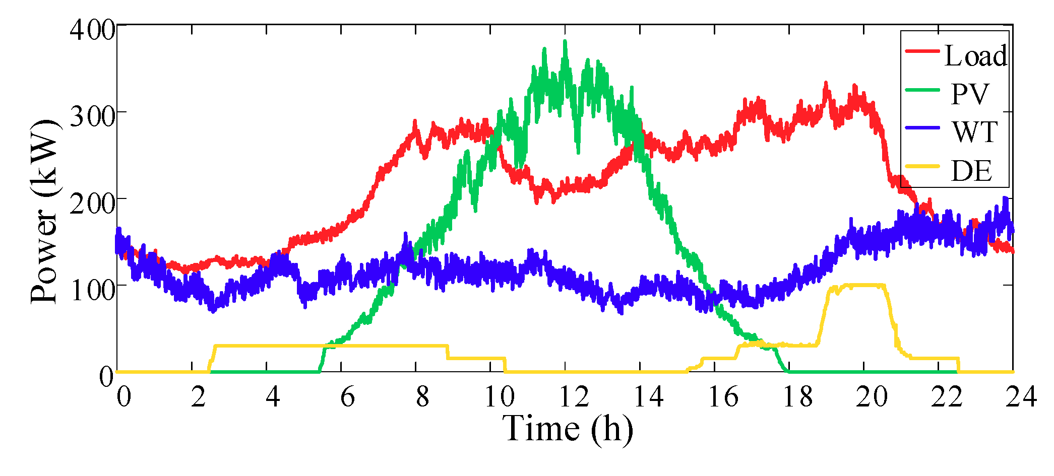
The load curve of the multi-microgrids, the total output curve of wind power and photovoltaics, and the corresponding power imbalance curve are shown in Figure 5, whose data source is an actual islanded multi-microgrid [34]. It can be seen that the power imbalance mainly occurs at 09:00–22:00. On the one hand, due to the large PV output at noon, there is a situation of excess power, and then a power shortage occurs after the peak load arrives at night.
After simulation, the power command of each microgrid basically follows the trend of the total power command. The regulation power of each unit throughout the day and the corresponding microgrid regulation cost are given in Table 3. The total regulation cost of MG1 and MG2 includes the forced cost corresponding to the unadjustable part of the output of the energy storage device. Since MG1 and MG2 are equipped with energy storage devices, the actual regulation costs of MG1 and MG2 are higher than that of MG3. The power command curves of each microgrid and the output curves of various distributed generations are shown in Figure 6 and Figure 7, respectively.
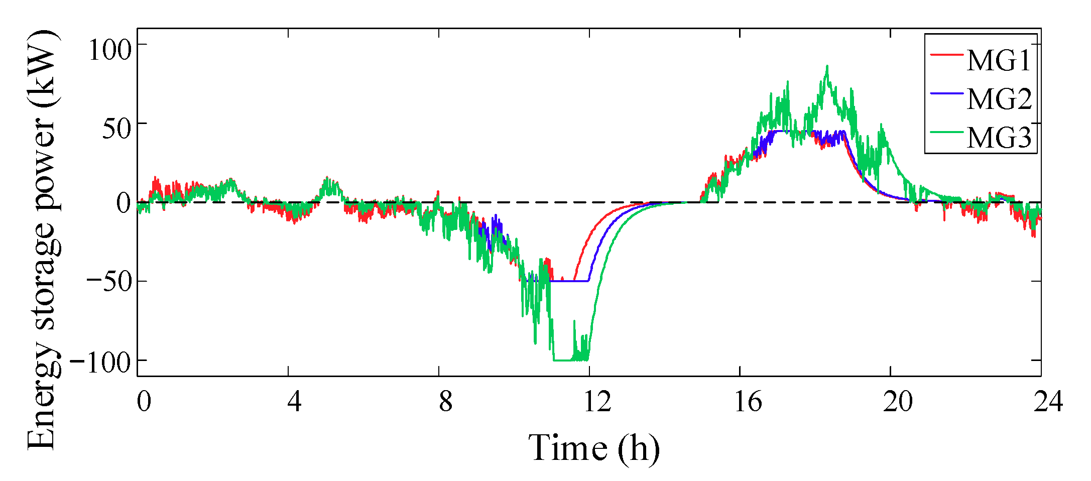
The results of charge and discharge power control of each microgrid energy storage unit are analyzed. The real-time power curve and SOC curve of each microgrid energy storage unit are shown in Figure 8 and Figure 9. It can be seen that the energy storage units of each microgrid are charged during the period of excessive photovoltaic output during the daytime, and discharge is completed during the peak load period, which is in accordance with the scheduling rules. The SOC change trend of each energy storage is basically the same, the capacity can be effectively utilized, and the power command allocation is reasonable.
The consensus convergence process of the two sections in the continuous simulation process is selected. The power command is ΔP = −205 kW, ΔP = +210 kW, respectively. The convergence process curves are shown in Figure 10 and Figure 11.
As can be seen from Figure 10, the current total power command is negative; the energy storage device in each microgrid charges to balance the corresponding unbalance amount, of which MG3 bears the largest regulation power. The reason is that the energy storage device of MG3 has the maximum capacity and rated power. When the energy storage devices of MG1 and MG2 reach the charge limit in the iteration process, it is necessary to adopt a regulation approach with a higher regulation cost. The energy storage device bears the low cost of power regulation. When each microgrid consumes a consensus regulation cost, MG3 would bear more power regulation.
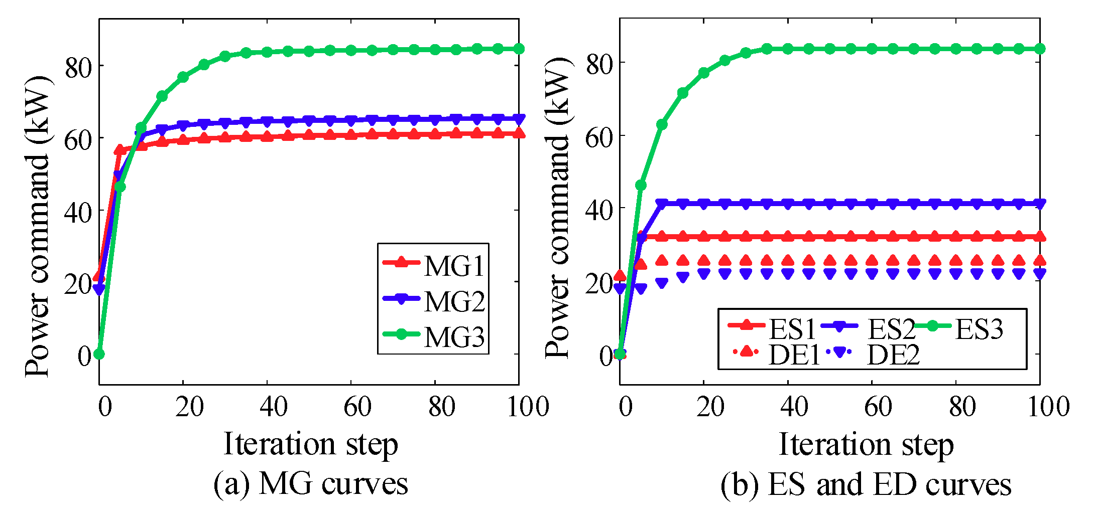
Similarly, as shown in Figure 11, when the current total power command is positive, each microgrid should increase its power generation to balance the corresponding unbalance. Each energy storage device discharges and two diesel generators have been turned on. When the output of ES1 and ES2 reaches the limit, the corresponding DE1 and DE2 gradually increase their output in the iteration process to promote the consensus regulation cost of each microgrid.
5.3. Comparative Analysis under Different Operation Modes
In order to reflect the advantages of the interconnected operation of microgrid and consensus power allocation model, the different operation modes of microgrid are compared and analyzed in this section, including the following three cases.
Mode 1: each microgrid operates independently [35].
Mode 2: the multi-microgrids are interconnected to form a microgrid cluster and each microgrid gives priority to autonomous operation. When its own power commands are different from the total power command of the microgrid cluster, it actively exchanges power with the microgrid cluster system [36].
Mode 3: the multi-microgrids are interconnected to form a microgrid cluster and the power allocation is based on the real-time cooperative power dispatch model established in this paper.
The three models are simulated continuously throughout the day and the regulation costs of each microgrid and microgrid cluster are given in Table 4. From the perspective of total regulation costs, the order is mode 1 > mode 2 > mode 3. Under mode 1, each microgrid operates independently and can only rely on its own supply for balance. When the generation and load are not balanced, there will be more abandoned power generation or load shedding, which would lead to the regulation costs being higher. The interconnection of the microgrids in mode 2 will reduce the regulation costs, which reflects the advantages of cluster operation of adjacent microgrids to a certain extent. However, the benefits of clustering operations have not been fully explored due to the priority of autonomous balance of microgrids. Mode 3 adopts the cooperative power dispatch strategy in which three microgrids in total are dispatched, and the energy transfer between each microgrid is mutually beneficial. Each microgrid allocates the regulation power reasonably according to the signal of regulation costs. Overall, the regulation capability of the microgrid cluster system has been optimized and the economy has been improved.
Figure 12 shows the MG1 power command under the three modes; the PV configuration of MG1 is the largest. It can be seen that the negative power command of MG1 at noon is smaller than that of the other two modes. Modes 1 and 2 decrease obviously at noon due to the bias towards autonomy. Under mode 3, due to the interconnection of each microgrid, the surplus output of MG1 can partly support the other two microgrids, thus reducing the negative power command in this period.
5.4. Comparison with Centralized Optimization
From the perspective of engineering applications, this paper compares the optimization of performance with the centralized optimization method. Aiming at the time section of power command P = +210 kW, a multiple population genetic algorithm (MPGA) [37] is selected for centralized optimization, in which the MPGA runs 10,000 times and the results are compared with those of the proposed consensus algorithm. The CPU (central processing unit) used in the simulation is 3.2 GHz, with 2 GB memory. A performance comparison of the two optimization approaches is given in Table 5.
From Table 5, it can be seen that the consensus algorithm belongs to distributed optimization technology, and its convergence time is greatly reduced compared with centralized optimization. As the scale of the microgrid clusters further increases, its advantages will become more obvious. MPGA is optimized 10,000 times and the optimal regulation cost is better than that of the consensus algorithm. It can be seen that the optimization result of the consensus algorithm is not the global optimal solution. The mean value of 10,000 optimization results obtained by MPGA is slightly lower than that of the consensus algorithm. According to statistics, the probability that the MPGA optimization result will be better than the consensus algorithm is about 30.69%. For the comparison of the optimization results shown in Figure 13, most of the optimization algorithms belong to static optimization, and it is difficult to solve the real-time dynamic problem.
5.5. Impact Analysis of Different TS
The value of time window TS will affect the results, as reflected in the power control of the energy storage. The reason is that the SOC electricity calculation of the energy storage is related to the length of the time window. This section compares the impact of different TS.
Taking ES3 as an example, the power curve and SOC curve of ES3 are shown in Figure 14 and Figure 15, respectively. Figure 14a shows the overall situation throughout the day and Figure 14b,c shows that the time period has a significant impact under different TS. Between 11:00 and 14:00, because of the high photovoltaic output at noon, the charge of the energy storage device is close to the SOC upper limit. When TS is small (such as TS = 10/60 h), the power command of the energy storage device will quickly drop to 0 and stop charging until the SOC reaches the upper limit. If TS is large (such as TS = 90/60 h), the energy storage device will start earlier to reduce the charge power. This proves that the control of the TS energy storage device tends to be conservative when TS is large, i.e., a larger TS can control the SOC of the energy storage device to avoid approaching the limit value.
However, the larger TS will increase the regulation cost of other controllable units, that is, the power regulation capability of the energy storage device is restricted in some time periods and the corresponding parts need to be borne by other controllable units. Table 6 gives the regulation cost under different values. Generally speaking, TS should not be too large or too small. The value of TS can be determined by reference to the type of energy storage battery and the consideration of the life of the energy storage battery, as well as the actual application requirements. The recommended value is 0.5–1.5 h.
6. Conclusions
In recent years, the development of microgrids has attracted interest to its related topics. This paper studies the real-time power allocation problem of islanded multi-microgrids. Considering the architecture and operational characteristics of islanded multi-microgrids, it is suitable to adopt a decentralized control architecture. A real-time cooperative power dispatch framework for islanded multi-microgrids is proposed. The microgrid regulation cost is modeled and a consensus algorithm is introduced to realize the power allocation. The conclusions are as follows:
- (1)
- The consensus power allocation algorithm proposed in this paper can allocate power reasonably and ensure the real-time power balance of the islanded multi-microgrids.
- (2)
- Each microgrid is guided by the regulation cost, and rationally optimizes the regulation power allocated by each microgrid, thereby improving the overall economics of the microgrid cluster system.
- (3)
- The communication burden of the control architecture is small. Each microgrid only needs a small amount of information from the local and neighboring microgrids, which can satisfy the real-time dynamic power allocation requirements of islanded multi-microgrids.
Author Contributions
All the authors have contributed to this paper in different aspects. X.Z. proposed the original concept and wrote the original draft. N.W. acted as supervisor and gave suggestions on paper improvement.
Funding
This research received no external funding.
Conflicts of Interest
The authors declare no conflict of interest.
Abbreviations and Nomenclature
| MG | microgrid |
| MMGs | multi-microgrids |
| CHP | combined heat and power |
| MGC | microgrid controller |
| ICA-GA | imperialist competitive algorithm‒genetic algorithm |
| GSO | glowworm swarm optimization |
| PV | photovoltaic |
| WT | wind turbine |
| ES | energy storage device |
| DE | diesel engine |
| IL | interruptible load |
| SOC | state of charge |
| DG | distributed generation |
| MPPT | maximum power point tracking |
| MPGA | multiple population genetic algorithm |
| time interval of power command | |
| current SOC calculated value | |
| previous actual SOC value | |
| energy storage system capacity | |
| energy storage system power limits | |
| energy storage system efficiency | |
| state duration window | |
| power command of the energy storage device | |
| regulation cost generated by power command | |
| total power imbalance | |
| SOC change caused by the SOC area with the | |
| unit regulation cost of ES | |
| maximum charge power | |
| maximum discharge power | |
| power command of the diesel generator | |
| unit generation cost of the diesel generator | |
| unit fuel coefficient of the diesel generator | |
| fuel unit cost of the diesel generator | |
| rated power of diesel generators | |
| upper limit of diesel generators output | |
| lower limit of diesel generators output | |
| upper limit of diesel generator power command | |
| rates of decreasing output of diesel generators | |
| rates of increasing output of diesel generators | |
| excess part of the current real-time output | |
| start coefficients of the diesel generator | |
| stop coefficients of the diesel generator | |
| power commands of interruptible load | |
| power command of distributed generation output reduction | |
| unit regulation cost of interruptible load | |
| unit regulation cost of distributed generation output reduction | |
| upper limit of interruptible load | |
| upper limit of distributed generation output reduction | |
| microgrid power command | |
| power command of the i-th microgrid | |
| regulation cost of the i-th microgrid | |
| total load of the i-th microgrid | |
| upper limit of the power regulation of the i-th microgrid | |
| lower limit of the power regulation of the i-th microgrid | |
| number of microgrid | |
| error adjustment step size | |
| power deviation commands | |
| convergence error |
References
- Hatziargyriou, N.; Asano, H.; Iravani, R.; Marnay, C. Microgrids. IEEE Power Energy Mag. 2007, 5, 78–94. [Google Scholar] [CrossRef]
- Katiraei, F.; Iravani, R.; Hatziargyriou, N.; Dimeas, A. Microgrids management. IEEE Power Energy Mag. 2008, 6, 54–65. [Google Scholar] [CrossRef]
- Che, L. Microgrids and distributed generation systems: Control, operation, coordination and planning. Diss. Theses-Gradworks 2015, 63, 33–39. [Google Scholar]
- Katiraei, F.; Iravani, M.R.; Lehn, P.W. Micro-grid autonomous operation during and subsequent to islanding process. IEEE Trans. Power Deliv. 2005, 20, 248–257. [Google Scholar] [CrossRef]
- Amoateng, D.O.; Al Hosani, M.; El Moursi, M.S.; Turitsyn, K.; Kirtley, J.L. Adaptive voltage and frequency control of islanded multi-microgrids. IEEE Trans. Power Syst. 2018, 33, 4454–4465. [Google Scholar] [CrossRef]
- Hualei, Z.; Shiwen, M.; Yu, W.; Zhang, F.; Chen, X.; Cheng, L. A survey of energy management in interconnected multi-microgrids. IEEE Access 2019, 7, 72158–72169. [Google Scholar]
- John, T.; Ping Lam, S. Voltage and frequency control during microgrid islanding in a multi-area multi-microgrid system. IET Gener. Transm. Distrib. 2017, 11, 1502–1512. [Google Scholar] [CrossRef]
- Farrokhabadi, M.; Canizares, C.A.; Bhattacharya, K. Frequency control in isolated/islanded microgrids through voltage regulation. IEEE Trans. Smart Grid 2017, 8, 1185–1194. [Google Scholar] [CrossRef]
- Chowdhury, D.; Khalid Hasan, A.; Rahman Khan, M.Z. Scalable DC microgrid architecture with phase shifted full bridge converter based power management unit. In Proceedings of the 2018 10th International Conference on Electrical and Computer Engineering (ICECE), Dhaka, Bangladesh, 20–22 December 2018; pp. 22–25. [Google Scholar]
- Khalid Hasan, A.; Chowdhury, D.; Rahman Khan, M. Scalable DC microgrid architecture with a one-way communication based control interface. In Proceedings of the 2018 10th International Conference on Electrical and Computer Engineering (ICECE), Dhaka, Bangladesh, 20–22 December 2018; pp. 265–268. [Google Scholar]
- Alipour, M.; Mohammadi-Ivatloo, B.; Zare, K. Stochastic scheduling of renewable and CHP based microgrids. IEEE Trans. Ind. Inform. 2015, 11, 1049–1058. [Google Scholar] [CrossRef]
- Wang, R.; Wang, P.; Xiao, G. A robust optimization approach for energy generation scheduling in microgrids. Energy Convers. Manag. 2015, 106, 597–607. [Google Scholar] [CrossRef]
- Luo, Z.; Wei, G.U.; Zhi, W.U.; Wang, Z.; Tan, Y. A robust optimization method for energy management of CCHP microgrid. J. Mod. Power Syst. Clean Energy 2018, 6, 132–144. [Google Scholar] [CrossRef]
- Palma-Behnke, R.; Benavides, C.; Lanas, F.; Severino, B.; Reyes, L.; Llanos, J.; Sáez, D. A microgrid energy management system based on the rolling horizon strategy. IEEE Trans. Smart Grid 2013, 4, 996–1006. [Google Scholar] [CrossRef]
- Solanki, B.V.; Canizares, C.A.; Kankar, B. Practical energy management systems for isolated microgrids. IEEE Trans. Smart Grid 2019, 10, 4762–4775. [Google Scholar] [CrossRef]
- Dou, C.X.; An, X.G.; Yue, D. Multi-agent system based energy management strategies for microgrid by using renewable energy source and load forecasting. Electr. Power Compon. Syst. 2016, 44, 2059–2072. [Google Scholar] [CrossRef]
- Wang, Z.; Feng, L.; Low, S.H.; Zhao, C.; Mei, S. Distributed frequency control with operational constraints, Part I: Per-node power balance. IEEE Trans. Smart Grid 2019, 10, 40–52. [Google Scholar] [CrossRef]
- Wang, Z.; Feng, L.; Low, S.H.; Zhao, C.; Mei, S. Distributed frequency control with operational constraints, Part II: Network power balance. IEEE Trans. Smart Grid 2019, 10, 53–64. [Google Scholar] [CrossRef]
- Hamed, M.G.; Mohammad, K. A novel optimal control method for islanded microgrids based on droop control using the ICA-GA algorithm. Energies 2017, 10, 485. [Google Scholar]
- Quynh, T.T.T.; Maria, L.D.S.; Riva Sanseverino, E.; Zizzo, G.; Pham, T. Driven primary regulation for minimum power losses operation in islanded microgrids. Energies 2018, 11, 2890. [Google Scholar]
- Sanseverino, E.R.; Silvestre, M.L.D.; Mineo, L.; Favuzza, S.; Nguyen, N.Q.; Tran, Q.T.T. A multi-agent system reinforcement learning based optimal power flow for islanded microgrids. In Proceedings of the 2016 IEEE 16th International Conference on Environment and Electrical Engineering (EEEIC), Florence, Italy, 7–10 June 2016; pp. 1–6. [Google Scholar]
- Li, Q.; Gao, D.W.; Zhang, H.; Wu, Z.; Wang, F.Y. Consensus-based distributed economic dispatch control method in power systems. IEEE Trans. Smart Grid 2019, 10, 941–954. [Google Scholar] [CrossRef]
- Yang, S.; Tan, S.; Xu, J. Consensus based approach for economic dispatch problem in a smart grid. IEEE Trans. Power Syst. 2013, 28, 4416–4426. [Google Scholar] [CrossRef]
- Pourbabak, H.; Luo, J.; Chen, T.; Su, W. A novel consensus-based distributed algorithm for economic dispatch based on local estimation of power mismatch. IEEE Trans. Smart Grid 2018, 9, 5930–5942. [Google Scholar] [CrossRef]
- Tang, Z.; Hill, D.J.; Liu, T. A novel consensus-based economic dispatch for microgrids. IEEE Trans. Smart Grid 2018, 9, 3920–3922. [Google Scholar] [CrossRef]
- Zhang, X.; Yu, T.; Yang, B.; Li, L. Virtual generation tribe based robust collaborative consensus algorithm for dynamic generation command dispatch optimization of smart grid. Energy 2016, 101, 34–51. [Google Scholar] [CrossRef]
- Lu, L.; Chu, C. Consensus-based droop control of isolated micro-grids by ADMM implementations. IEEE Trans. Smart Grid 2018, 9, 5101–5112. [Google Scholar] [CrossRef]
- Liu, Y.; Li, Y.; Xin, H.; Gooi, H.B.; Pan, J. Distributed optimal tie-line power flow control for multiple interconnected AC microgrids. IEEE Trans. Power Syst. 2019, 34, 1869–1880. [Google Scholar] [CrossRef]
- Zhao, B.; Wang, X.; Lin, D.; Calvin, M.M.; Morgan, J.C.; Qin, R.; Wang, C. Energy management of multiple-microgrids based on a system of systems architecture. IEEE Trans. Power Syst. 2018, 33, 6410–6421. [Google Scholar] [CrossRef]
- Bui, V.H.; Hussain, A.; Kim, H.M. A multiagent-based hierarchical energy management strategy for multi-microgrids considering adjustable power and demand response. IEEE Trans. Smart Grid 2018, 9, 1323–1333. [Google Scholar] [CrossRef]
- Asimakopoulou, G.E.; Dimeas, A.L.; Hatziargyriou, N.D. Leader-follower strategies for energy management of multi-microgrids. IEEE Trans. Smart Grid 2013, 4, 1909–1916. [Google Scholar] [CrossRef]
- Xu, Y.; Li, Z. Distributed optimal resource management based on the consensus algorithm in a microgrid. IEEE Trans. Ind. Electron. 2015, 62, 2584–2592. [Google Scholar] [CrossRef]
- Zhang, Z.; Chow, M.Y. Convergence analysis of the incremental cost consensus algorithm under different communication network topologies in a smart grid. IEEE Trans. Power Syst. 2012, 27, 1761–1768. [Google Scholar] [CrossRef]
- Alegria, E.; Brown, T.; Minear, E.; Lasseter, R.H. CERTS microgrid demonstration with large-scale energy storage and renewable generation. IEEE Trans. Smart Grid 2014, 5, 937–943. [Google Scholar] [CrossRef]
- Olivares, D.E.; Canizares, C.A.; Kazerani, M. A centralized energy management system for isolated microgrids. IEEE Trans. Smart Grid 2014, 5, 1864–1875. [Google Scholar] [CrossRef]
- Fang, X.; Yang, Q.; Wang, J.; Yan, W. Coordinated dispatch in multiple cooperative autonomous islanded microgrids. Appl. Energy 2016, 162, 40–48. [Google Scholar] [CrossRef]
- Wang, B.; Li, I. Load balancing task scheduling based on multi-population genetic algorithm in cloud computing. In Proceedings of the 2016 35th IEEE Chinese Control Conference (CCC), Chengdu, China, 27–29 July 2016; pp. 5261–5266. [Google Scholar]
Figure 1.
Real-time cooperative dispatch framework for islanded multi-microgrids.

Figure 2.
Schematic diagram for energy storage system SOC subarea: (a) Description of the SOC operating area; (b) Description of the regulation cost.
Figure 2.
Schematic diagram for energy storage system SOC subarea: (a) Description of the SOC operating area; (b) Description of the regulation cost.

Figure 3.
Regulation cost function of microgrids.

Figure 4.
Flowchart of consensus algorithm for real-time cooperative power dispatch of islanded multi-microgrids.
Figure 4.
Flowchart of consensus algorithm for real-time cooperative power dispatch of islanded multi-microgrids.

Figure 5.
Power unbalance of multi-microgrids.

Figure 6.
Power command curve of each microgrid.

Figure 7.
Power curve of DGs.

Figure 8.
Power curve of each ES.

Figure 9.
SOC curve of each ES.

Figure 10.
Consensus convergence process (ΔP = −205 kW): (a) Description of the three MG iteration process; (b) Description of the three ES iteration process.
Figure 10.
Consensus convergence process (ΔP = −205 kW): (a) Description of the three MG iteration process; (b) Description of the three ES iteration process.

Figure 11.
Consensus convergence process (ΔP = +210 kW): (a) Description of the three MG iteration processes; (b) Description of the three ES and two DE iteration processed.
Figure 11.
Consensus convergence process (ΔP = +210 kW): (a) Description of the three MG iteration processes; (b) Description of the three ES and two DE iteration processed.

Figure 12.
Power command of MG1 under the three modes.

Figure 13.
Comparison of optimization results.

Figure 14.
Power curve of ES3 with different Ts: (a) Description of the Power curve of ES3 with different Ts from 0:00 to 24: 00; (b) Description of the Power curve of ES3 with different Ts from 10:30 to 14: 20; (c) Description of the Power curve of ES3 with different Ts from 18:40 to 22: 20.
Figure 14.
Power curve of ES3 with different Ts: (a) Description of the Power curve of ES3 with different Ts from 0:00 to 24: 00; (b) Description of the Power curve of ES3 with different Ts from 10:30 to 14: 20; (c) Description of the Power curve of ES3 with different Ts from 18:40 to 22: 20.

Figure 15.
SOC curve of ES3 with different Ts.


Table 1.
Equipment parameters of multi-microgrids.
| Equipment Parameters | MG1 | MG2 | MG3 |
|---|---|---|---|
| PV capacity/kW | 180 | 100 | 120 |
| WT capacity/kW | 40 | 80 | 80 |
| ES capacity/kWh | 200 | 200 | 300 |
| ES rated power/kW | 50 | 50 | 100 |
| ES efficiency η | 0.9 | 0.9 | 0.9 |
| ES initial SOC | 0.34 | 0.25 | 0.21 |
| DE rated power/kW | 50 | 50 | - |
| DE increase output rate/(kW/min) | 2 | 2 | - |
| DE decrease output rate/(kW/min) | 2 | 2 | - |
| Maximum load/kW | 130 | 180 | 140 |
Table 2.
Parameters of regulating cost.
| Parameters of Regulating Cost ($/kWh) | MG1 | MG2 | MG3 |
|---|---|---|---|
| rES1 | 0.05 | 0.05 | 0.05 |
| rES2 | 0.1 | 0.1 | 0.1 |
| rES3 | 0.25 | 0.25 | 0.25 |
| rDE | 1.4 | 1.4 | 1.4 |
| rDG | 1.6 | 1.6 | 1.6 |
| rIL | 1.6 | 1.9 | 1.8 |
Table 3.
Regulation power and cost.
| MG1 | MG2 | MG3 | Total | |
|---|---|---|---|---|
| Diesel power generation (kWh) | 248.07 | 260.88 | 0 | 508.95 |
| Load shedding (kWh) | 9.63 | 8.00 | 6.18 | 23.81 |
| Abandoned power generation (kWh) | 120.77 | 116.38 | 97.09 | 334.25 |
| Regulation cost ($) | 484.06 | 498.88 | 140.76 | 1123.70 |
Table 4.
Regulation costs under the three modes.
| Microgrid | Regulation Cost ($) | ||
|---|---|---|---|
| Mode 1 | Mode 2 | Mode 3 | |
| MG1 | 597.86 | 560.29 | 484.06 |
| MG2 | 694.19 | 644.66 | 498.88 |
| MG3 | 317.22 | 338.23 | 140.76 |
| Total | 1609.27 | 1543.18 | 1123.70 |
Table 5.
Comparison of optimization performance.
| MPGA | Consensus Algorithmic | ||
|---|---|---|---|
| Regulation cost ($) | optimal | 20.35 | 21.16 |
| mean | 23.44 | ||
| Optimization time (s) | mean | 1.66 | 0.02 |
| Optimization approach | centralized, static | distributed, dynamic | |
Table 6.
Regulation cost with different Ts.
| TS (h) | MG1 Regulation Cost ($) | MG2 Regulation Cost ($) | MG3 Regulation Cost ($) | Total ($) |
|---|---|---|---|---|
| 10/60 | 472.14 | 493.30 | 146.29 | 1111.73 |
| 30/60 | 484.06 | 498.88 | 140.76 | 1123.70 |
| 60/60 | 493.24 | 512.18 | 141.82 | 1147.24 |
| 90/60 | 515.62 | 532.72 | 147.83 | 1196.17 |
© 2019 by the authors. Licensee MDPI, Basel, Switzerland. This article is an open access article distributed under the terms and conditions of the Creative Commons Attribution (CC BY) license (http://creativecommons.org/licenses/by/4.0/).
Share and Cite
MDPI and ACS Style
Zhai, X.; Wang, N. Multi-Agent Consensus Algorithm-Based Optimal Power Dispatch for Islanded Multi-Microgrids. Processes 2019, 7, 679. https://0-doi-org.brum.beds.ac.uk/10.3390/pr7100679
AMA Style
Zhai X, Wang N. Multi-Agent Consensus Algorithm-Based Optimal Power Dispatch for Islanded Multi-Microgrids. Processes. 2019; 7(10):679. https://0-doi-org.brum.beds.ac.uk/10.3390/pr7100679
Chicago/Turabian StyleZhai, Xingli, and Ning Wang. 2019. "Multi-Agent Consensus Algorithm-Based Optimal Power Dispatch for Islanded Multi-Microgrids" Processes 7, no. 10: 679. https://0-doi-org.brum.beds.ac.uk/10.3390/pr7100679
Note that from the first issue of 2016, this journal uses article numbers instead of page numbers. See further details here.