Finite Element Analysis on Bingham–Papanastasiou Viscoplastic Flow in a Channel with Circular/Square Obstacles: A Comparative Benchmarking

Abstract
:1. Introduction
2. Mathematical Formulation
3. Numerical Procedure
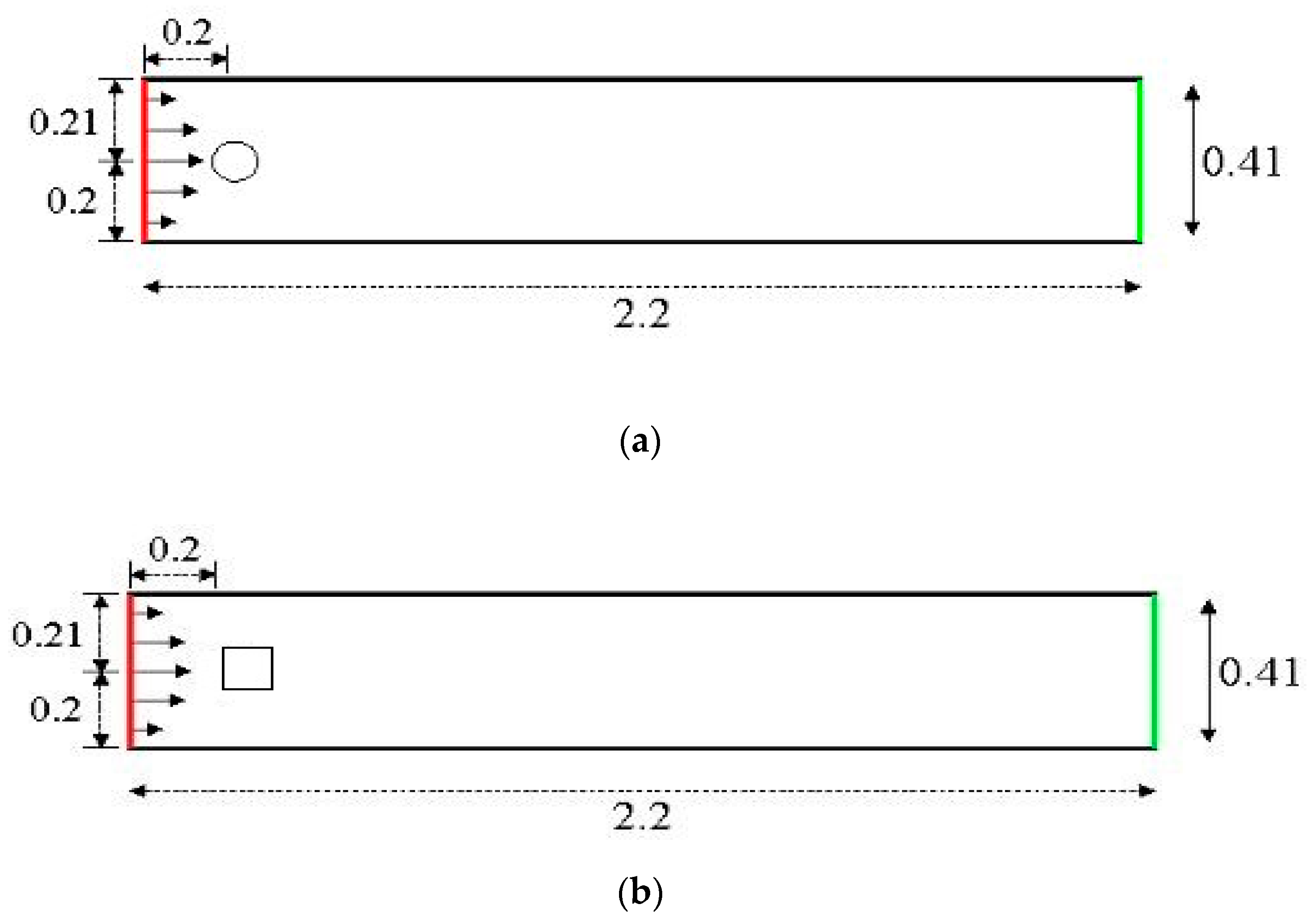
4. Flow Configuration and Numerical Results
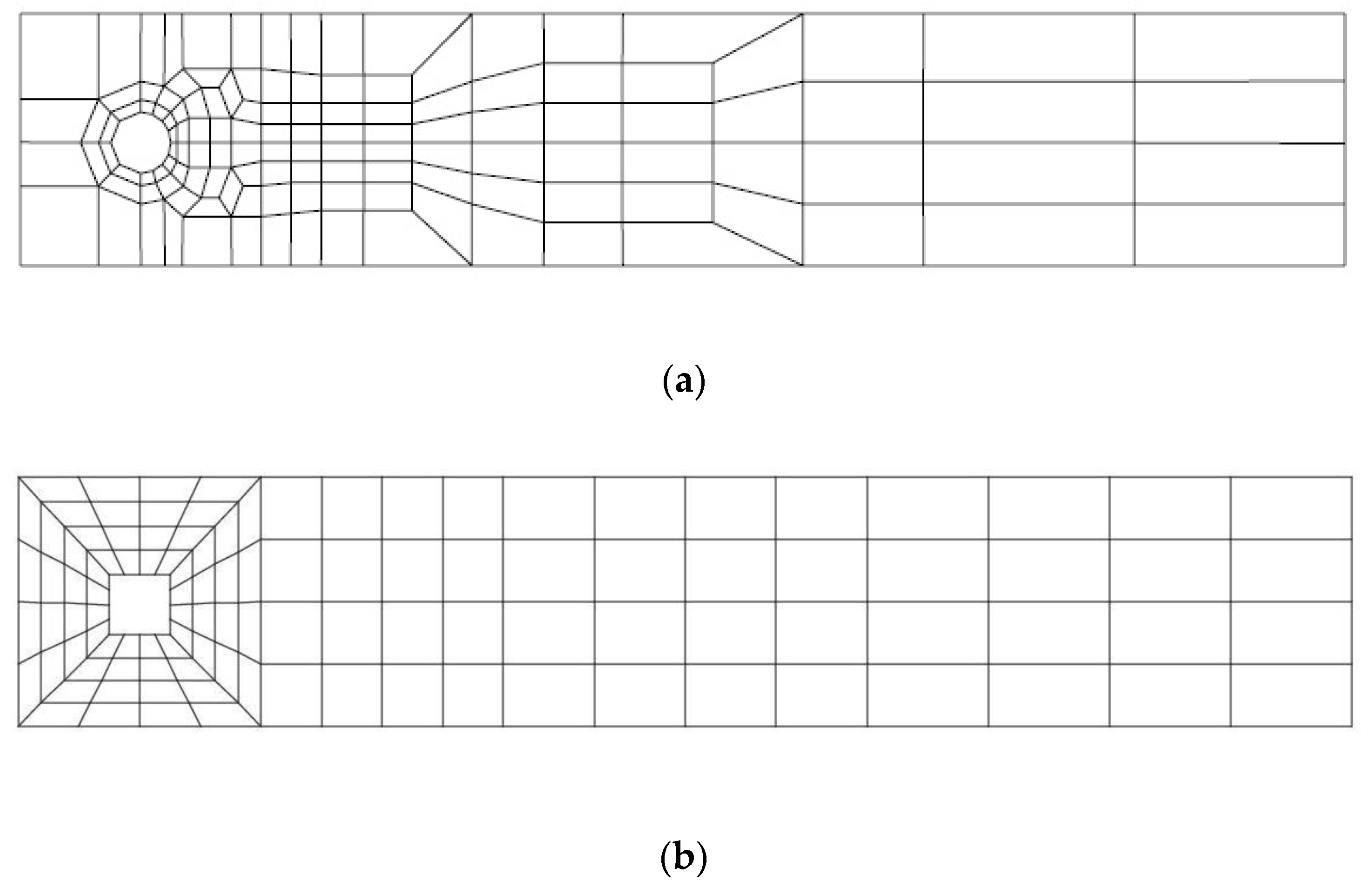
4.1. Code Validation and Grid Independency
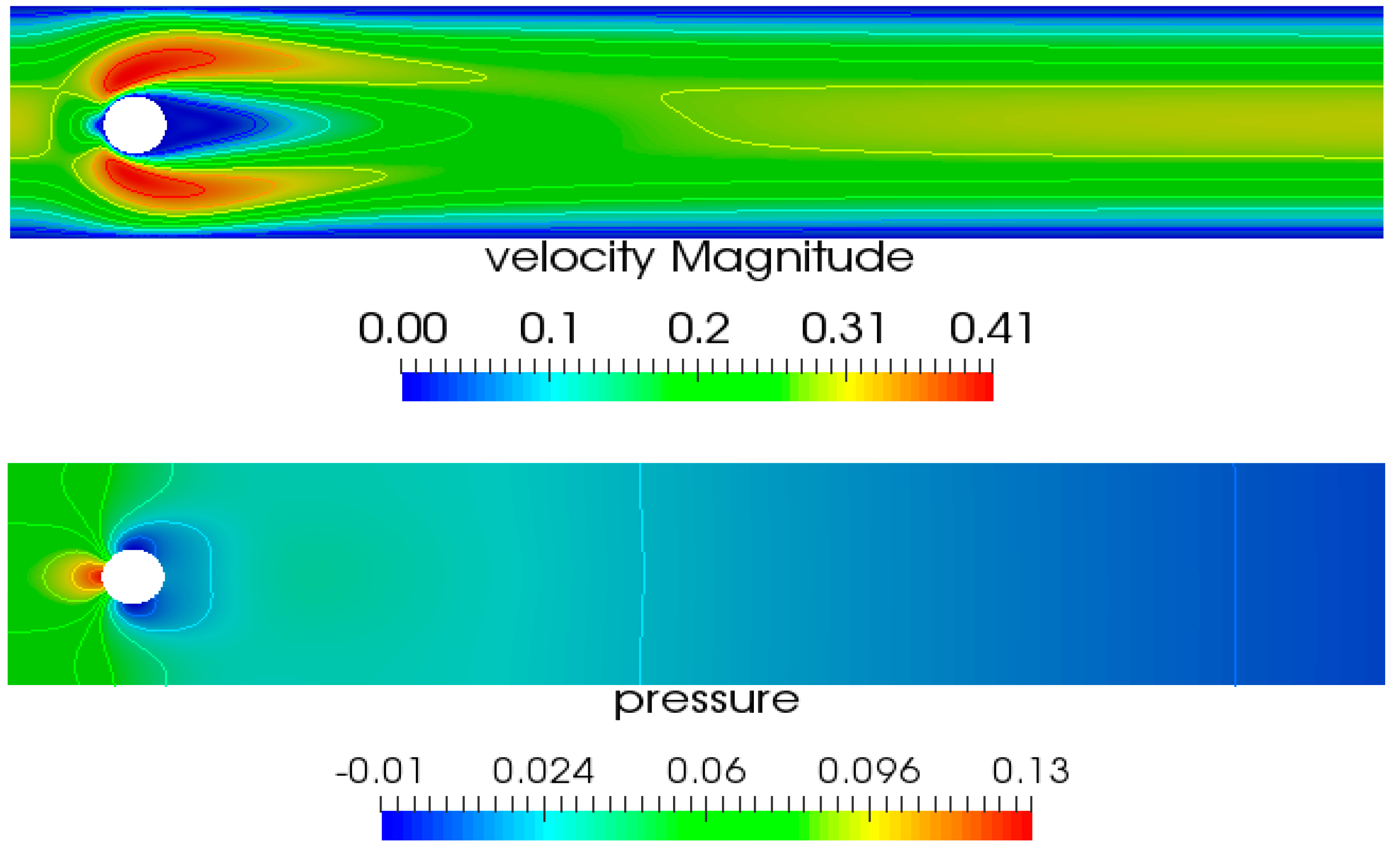
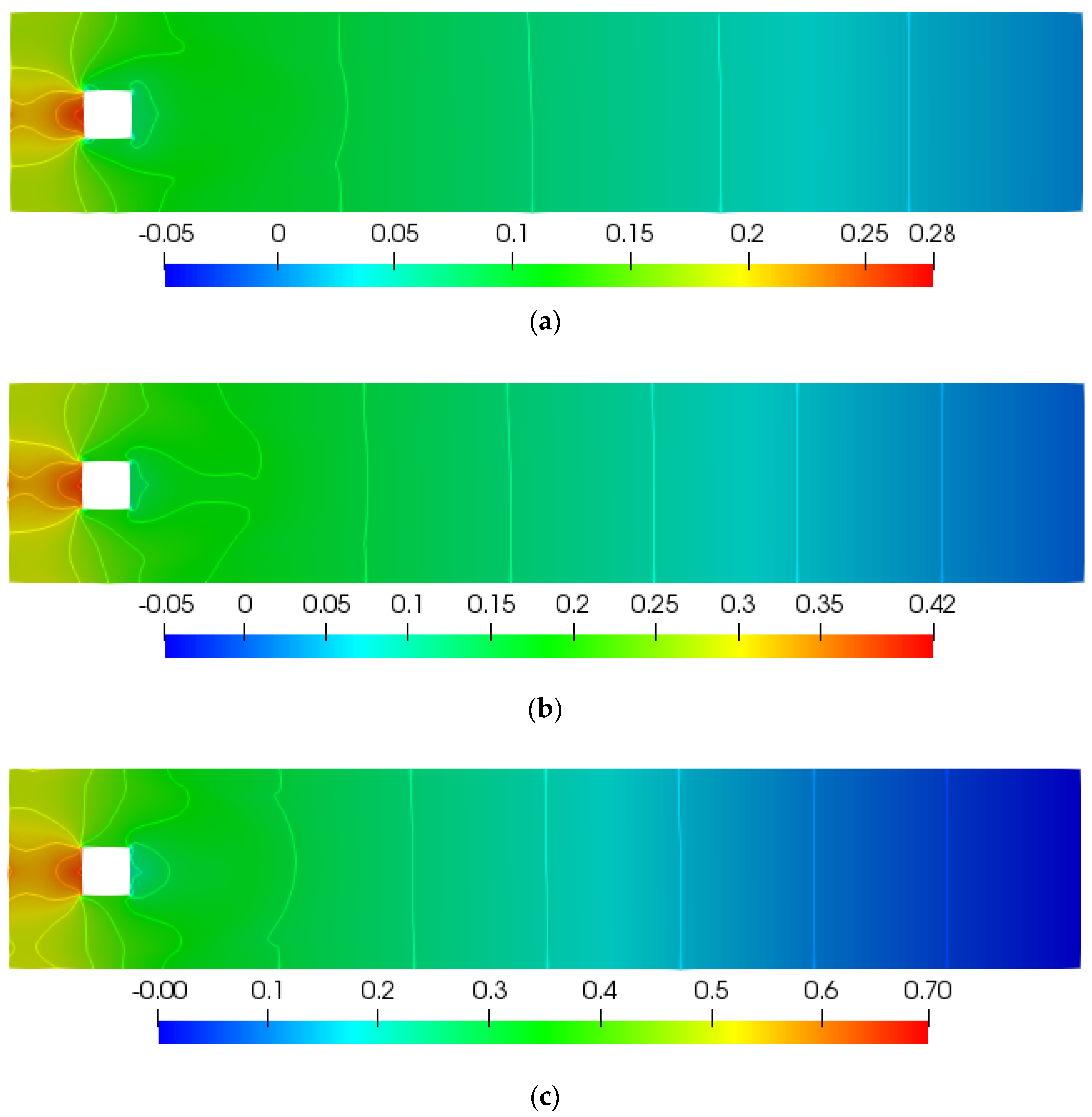
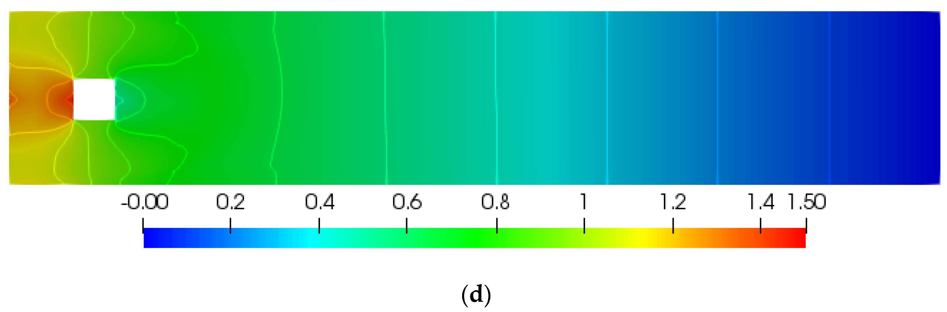
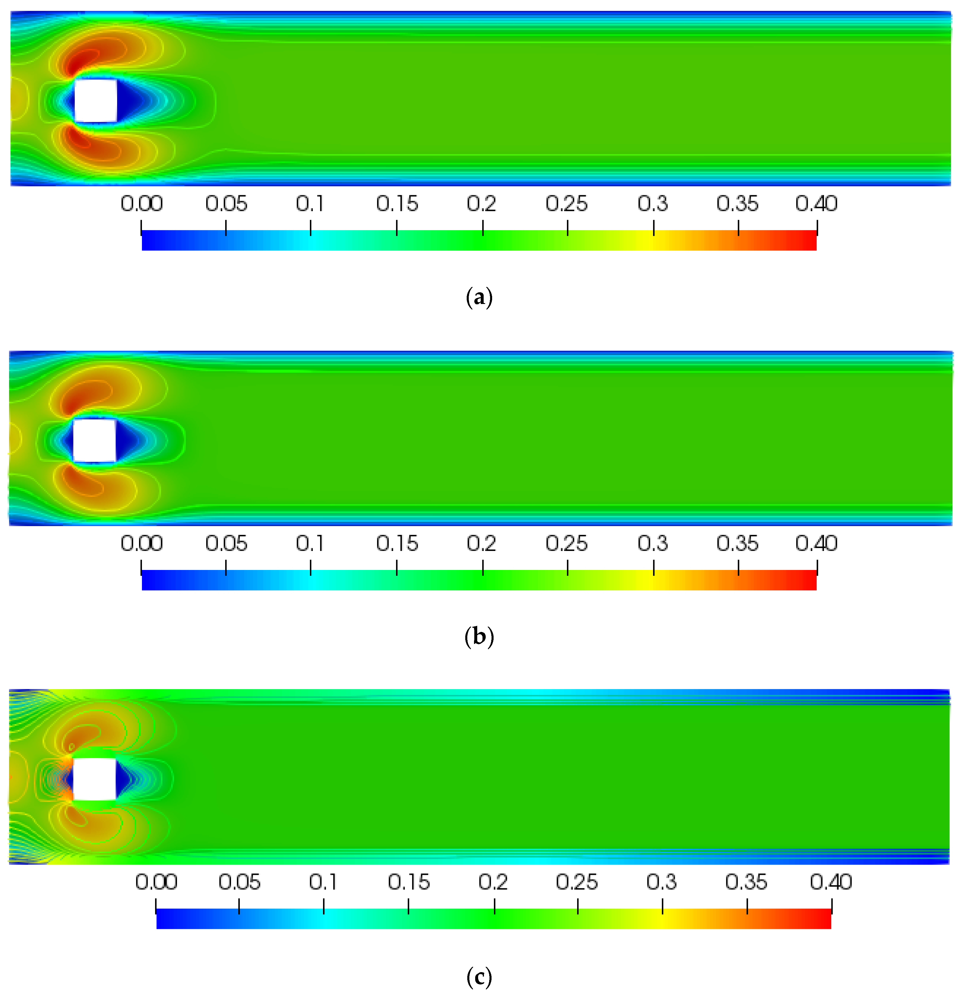
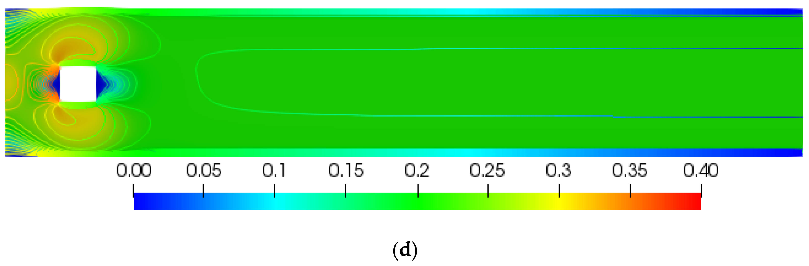
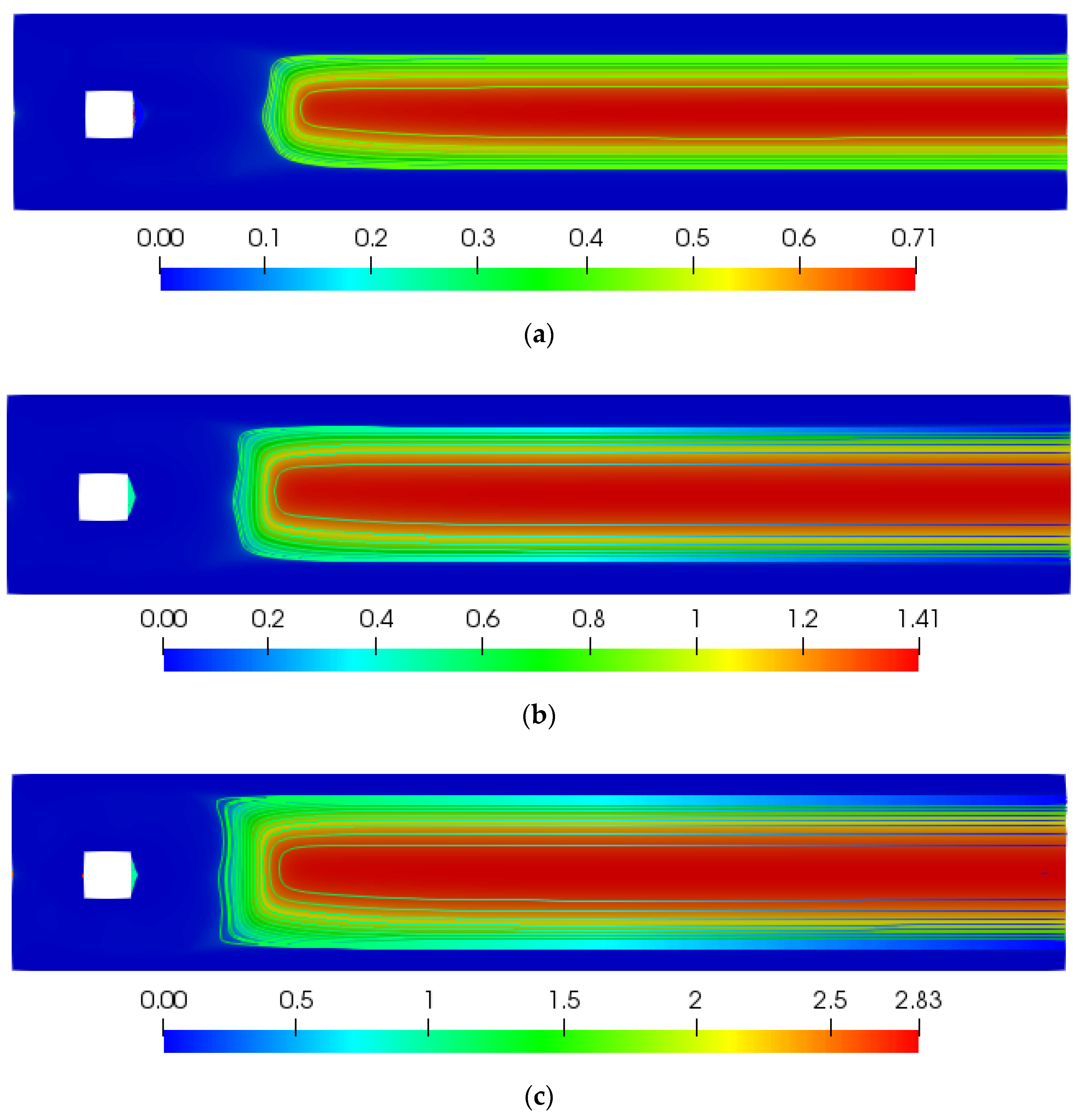
4.2. Further Parametric Study: Graphical and Tabular Results
5. Conclusions and Outlook
Author Contributions
Funding
Acknowledgments
Conflicts of Interest
Nomenclature
| Yield Stress | |
| Plastic Viscosity | |
| Stress Tensor | |
| Rate of Strain Tensor | |
| Dimensional Velocity Vector | |
| Dimensionless Velocity Vector | |
| Reference Velocity | |
| Shear Rate | |
| Dimensional pressure | |
| Dimensionless pressure | |
| Dimensional Stress growth parameter | |
| M | Dimensionless Stress growth parameter |
| Reynold number | |
| Bingham number | |
| #EL | Number of Elements |
| #DOF | Number of degrees of freedom |
| Drag Coefficient | |
| Lift Coefficient |
References
- Shwedov, F.N. La Rigidite DE Liquides, Rapports PRésentés AU Congrès International DE Physique Paris 1; Société nouvelle de librarie et d’édition: Paris, France, 1900; pp. 478–486. [Google Scholar]
- Bingham, E.C. Fluidity and Plasticity; McGraw-Hill: New York, NY, USA, 1922. [Google Scholar]
- Herschel, W.H.; Bulkley, R. Konsistenzmessungen von Gummi-Benzollösungen. Colloid Polym. Sci. 1926, 39, 291–300. [Google Scholar] [CrossRef]
- Casson, N. A flow equation for pigment-oil suspensions of the printing ink type. In Rheology of Disperse Systems; Pergamon Press: London, UK, 1959; pp. 84–104. [Google Scholar]
- Bird, R.B.; Dai, G.; Yarusso, B.J. The Rheology and Flow of Viscoplastic Materials. Rev. Chem. Eng. 1983, 1, 1–70. [Google Scholar] [CrossRef]
- Bird, R.B.; Armstrong, R.C.; Hassager, O. Dynamics of Polymeric Liquids, 2nd ed.; Fluid Mechanics; Wiley: New York, NY, USA, 1987; Volume 1. [Google Scholar]
- Bercovier, M.; Engelman, M. A finite-element method for incompressible non-Newtonian flows. J. Comput. Phys. 1980, 36, 313–326. [Google Scholar] [CrossRef]
- Papanastasiou, T.C. Flows of materials with yield. J. Rheol. 1987, 31, 385–404. [Google Scholar] [CrossRef]
- Fortin, M.; Glowinski, R. Augmented Lagrangian Methods: Applications to the Numerical Solution of Boundary-Value Problems; Elsevier: Amsterdam, The Netherlands, 1983. [Google Scholar]
- Glowinski, R. Numerical Methods for for non-Linear Variational Problems; Springer: New York, NY, USA, 1984. [Google Scholar]
- Barnes, H.A. The yield stress—A review or ‘παντα ρει’—Everything flows? J. Non-Newton. Fluid Mech. 1999, 81, 133–178. [Google Scholar] [CrossRef]
- Syrakos, A.; Georgiou, G.C.; Alexandrou, A.N. Solution of the square lid-driven cavity flow of a Bingham plastic using the finite volume method. J. Non-Newton. Fluid Mech. 2013, 195, 19–31. [Google Scholar] [CrossRef] [Green Version]
- Mitsoulis, E.; Zisis, T. Flow of Bingham plastics in a lid-driven square cavity. J. Non-Newton. Fluid Mech. 2001, 101, 173–180. [Google Scholar] [CrossRef]
- Dean, E.J.; Glowinski, R.; Guidoboni, G. On the numerical simulation of Bingham visco-plastic flow: Old and new results. J. Non-Newton. Fluid Mech. 2007, 142, 36–62. [Google Scholar] [CrossRef]
- Kefayati, G.H.R.; Huilgol, R.R. Lattice Boltzmann method for the simulation of the steady flow of a Bingham fluid in a pipe of square cross-section. Eur. J. Mech.-B/Fluids 2017, 65, 412–422. [Google Scholar] [CrossRef]
- Kefayati, G. FDLBM simulation of magnetic field effect on non-Newtonian blood flow in a cavity driven by the motion of two facing lids. Powder Technol. 2014, 253, 325–337. [Google Scholar] [CrossRef]
- Mahmood, R.; Kousar, N.; Yaqub, M.; Jabeen, K. Numerical simulations of the square lid driven cavity flow of Bingham fluids using nonconforming finite elements coupled with a direct solver. Adv. Math. Phys. 2017, 2, 1–10. [Google Scholar] [CrossRef]
- Schäfer, M.; Turek, S.; Durst, F.; Krause, E.; Rannacher, R. Benchmark Computations of Laminar Flow around a Cylinder. Notes Numer. Fluid Mech. (NNFM) 1996, 48, 547–566. [Google Scholar]
- Williamson, C.H.K. Vortex Dynamics in the Cylinder Wake. Annu. Rev. Fluid Mech. 1996, 28, 477–539. [Google Scholar] [CrossRef]
- Hussain, S.; Schieweck, F.; Turek, S. An efficient and stable finite element solver of higher order in space and time for nonstationary incompressible flow. Int. J. Numer. Methods Fluids 2013, 73, 927–952. [Google Scholar] [CrossRef]
- Kanaris, N.; Grigoriadis, D.; Kassinos, S. Three dimensional flow around a circular cylinder confined in a plane channel. Phys. Fluids 2011, 23, 064106. [Google Scholar] [CrossRef] [Green Version]
- Rajani, B.; Kandasamy, A.; Majumdar, S. Numerical simulation of laminar flow past a circular cylinder. Appl. Math. Model. 2009, 33, 1228–1247. [Google Scholar] [CrossRef]
- Adachi, K.; Yoshioka, N. On creeping flow of a visco-plastic fluid past a circular cylinder. Chem. Eng. Sci. 1973, 28, 215–226. [Google Scholar] [CrossRef]
- Tokpavi, D.L.; Magnin, A.; Jay, P. Very slow flow of Bingham viscoplastic flow around a circular cylinder. J. Non-Newtonian Fluid Mech. 2008, 154, 65–76. [Google Scholar] [CrossRef]
- Tokpavi, D.L.; Jay, P.; Magnin, A.; Jossic, L. Experimental study of the very slow flow of a yield stress fluid around a circular cylinder. J. Non-Newtonian Fluid Mech. 2009, 164, 35–44. [Google Scholar] [CrossRef]
- Nirmalkar, N.; Chhabra, R.; Poole, R. Laminar forced convection heat transfer from a heated square cylinder in a Bingham plastic fluid. Int. J. Heat Mass Transf. 2013, 56, 625–639. [Google Scholar] [CrossRef]
- Mossaz, S.; Jay, P.; Magnin, A. Non-recirculating and recirculating inertial flows of a viscoplastic fluid around a cylinder. J. Non-Newtonian Fluid Mech. 2012, 177, 64–75. [Google Scholar] [CrossRef]
- Syrakos, A.; Georgiou, G.C.; Alexandrou, A.N. Thixotropic flow past a cylinder. J. Non-Newton. Fluid Mech. 2015, 220, 44–56. [Google Scholar] [CrossRef] [Green Version]
- Syrakos, A.; Georgiou, G.C.; Alexandrou, A.N. Cessation of the lid-driven cavity flow of Newtonian and Bingham fluids. Rheol. Acta 2016, 55, 51–66. [Google Scholar] [CrossRef]
- Hussain, S.; Schieweck, F.; Turek, S. Efficient Newton-multigrid solution techniques for higher order space–time Galerkin discretizations of incompressible flow. Appl. Numer. Math. 2014, 83, 51–71. [Google Scholar] [CrossRef]
- Matthies, G.; Tobiska, L. The Inf-Sup Condition for the Mapped Qk-Pk-1disc Element in Arbitrary Space Dimensions. Computing 2002, 69, 119–139. [Google Scholar] [CrossRef]
- Davis, T.A. UMFPACK-an unsymmetric-pattern multifrontal method with a column pre-ordering strategy. ACM Trans. Math. Softw. 2006, 30, 196–199. [Google Scholar] [CrossRef]
- Mahmood, R.; Kousar, N.; Usman, K.; Mehmood, A. Finite element simulations for stationary Bingham fluid flow past a circular cylinder. J. Braz. Soc. Mech. Sci. Eng. 2018, 40, 459. [Google Scholar] [CrossRef]


| Lev | Circular Cylinder | Square Cylinder | ||
|---|---|---|---|---|
| #EL | #DOFs | #EL | #DOFs | |
| 1 | 130 | 1534 | 112 | 1344 |
| 2 | 520 | 5928 | 448 | 5152 |
| 3 | 2080 | 23,296 | 1792 | 20,160 |
| 4 | 8320 | 92,352 | 7168 | 79,744 |
| 5 | 33,280 | 367,744 | 28,672 | 317,184 |
| 6 | 133,120 | 1,467,648 | 114,688 | 1,265,152 |
| Lev | ||
|---|---|---|
| 1 | 4.811786 × 10⁻³ | 5.330670 |
| 2 | 9.006015 × 10⁻³ | 5.500019 |
| 3 | 1.042621 × 10⁻² | 5.557633 |
| 4 | 1.042621 × 10⁻² | 5.557633 |
| 5 | 1.060405 × 10⁻² | 5.578171 |
| 6 | 1.061492 × 10⁻² | 5.579198 |
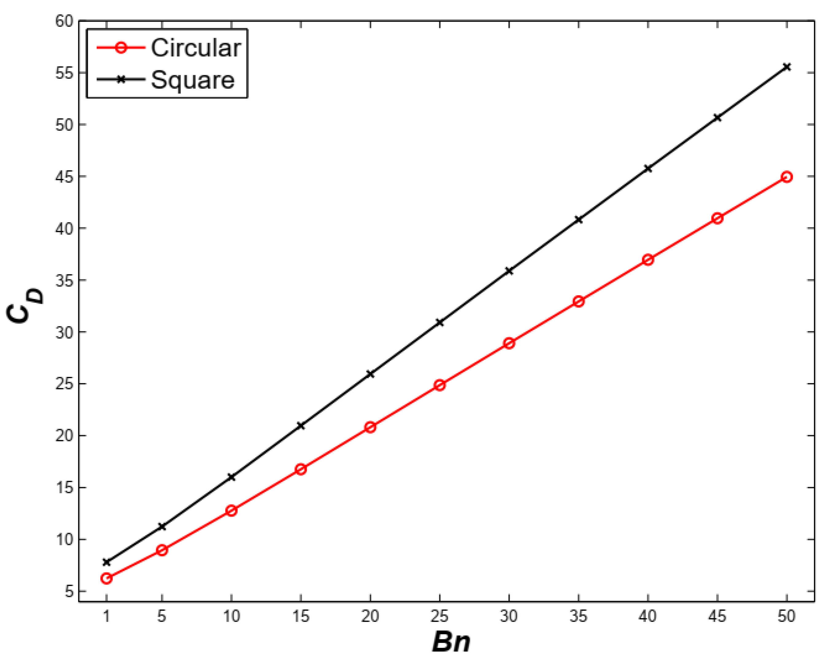
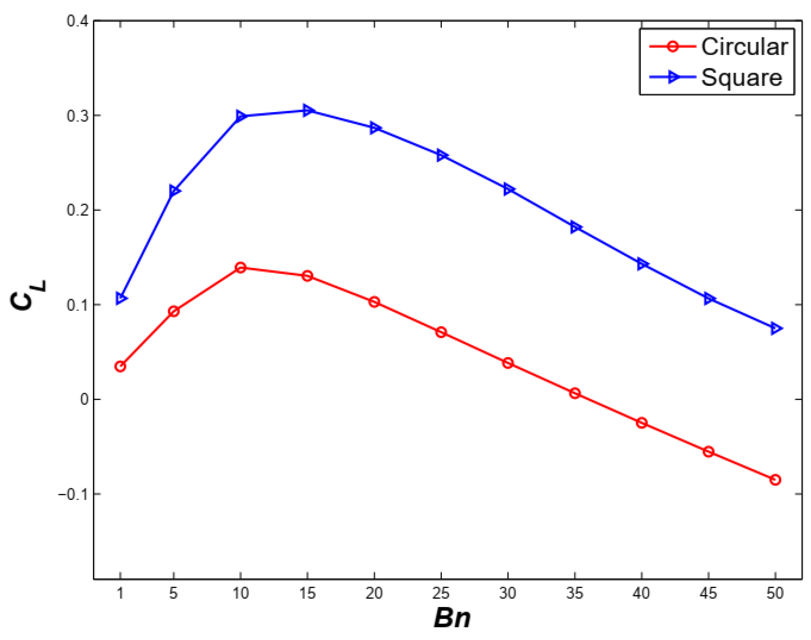
| Circular Obstacle | Square Obstacle | |||
|---|---|---|---|---|
| 1 | 6.237896 | 3.471506 × 10⁻² | 7.802527 | 1.066414 × 10⁻¹ |
| 5 | 8.956400 | 9.303962 × 10⁻² | 11.23487 | 2.200490 × 10⁻¹ |
| 10 | 12.76176 | 1.392485 × 10⁻¹ | 16.00524 | 2.989600 × 10⁻¹ |
| 15 | 16.76099 | 1.304087 × 10⁻¹ | 20.95338 | 3.052176 × 10⁻¹ |
| 20 | 20.81272 | 1.029614 × 10⁻¹ | 25.93892 | 2.867756 × 10⁻¹ |
| 25 | 24.86881 | 7.090231 × 10⁻² | 30.91964 | 2.579676 × 10⁻¹ |
| 30 | 28.91413 | 3.833286 × 10⁻² | 35.88314 | 2.221996 × 10⁻¹ |
| 35 | 32.94459 | 6.344714 × 10⁻³ | 40.82713 | 1.821432 × 10⁻¹ |
| 40 | 36.95979 | −2.481294 × 10⁻² | 45.75258 | 1.430765 × 10⁻¹ |
| 45 | 40.96059 | −5.530762 × 10⁻² | 50.66154 | 1.064771 × 10⁻¹ |
| 50 | 44.94819 | −8.510983 × 10⁻² | 55.55585 | 7.492779 × 10⁻² |
© 2020 by the authors. Licensee MDPI, Basel, Switzerland. This article is an open access article distributed under the terms and conditions of the Creative Commons Attribution (CC BY) license (http://creativecommons.org/licenses/by/4.0/).
Share and Cite
Mehmood, A.; Khan, W.A.; Mahmood, R.; Rehman, K.U. Finite Element Analysis on Bingham–Papanastasiou Viscoplastic Flow in a Channel with Circular/Square Obstacles: A Comparative Benchmarking. Processes 2020, 8, 779. https://0-doi-org.brum.beds.ac.uk/10.3390/pr8070779
Mehmood A, Khan WA, Mahmood R, Rehman KU. Finite Element Analysis on Bingham–Papanastasiou Viscoplastic Flow in a Channel with Circular/Square Obstacles: A Comparative Benchmarking. Processes. 2020; 8(7):779. https://0-doi-org.brum.beds.ac.uk/10.3390/pr8070779
Chicago/Turabian StyleMehmood, Asif, Waqar A. Khan, Rashid Mahmood, and Khalil Ur Rehman. 2020. "Finite Element Analysis on Bingham–Papanastasiou Viscoplastic Flow in a Channel with Circular/Square Obstacles: A Comparative Benchmarking" Processes 8, no. 7: 779. https://0-doi-org.brum.beds.ac.uk/10.3390/pr8070779