Article

Experimental and Numerical Study on Hydraulic Performance of Chevron Brazed Plate Heat Exchanger at Low Reynolds Number

1
College of Mechanical Engineering, Zhejiang University of Technology, Hangzhou 310023, China
2
IAE Suzhou Technologies Co., Ltd., Suzhou 215100, China
3
Guodian Han Chuan Power Generation Co., Ltd., Hanchuan 431600, China
4
Ningbo Mingxin Chemical Machinery Co., Ltd., Ningbo 315200, China
*
Author to whom correspondence should be addressed.
Submission received: 24 July 2020 / Revised: 23 August 2020 / Accepted: 28 August 2020 / Published: 1 September 2020
(This article belongs to the Section Energy Systems)

Abstract

:
Few experiments have been performed to investigate the hydraulic performance in a chevron brazed plate heat exchanger (BPHE) with the narrow channel at lower Reynolds number. The hydraulic characteristics of seven types of chevron BPHEs were investigated experimentally and numerical simulation revealed the effects of structural parameters on hydraulic performances. The correlations between friction factor f and Re were fitted out based on more than 500 sets of pressure drop data. The research results show that there is a power-law between f and Re; which has a similar trend but a different amplitude for different plates, and the exponent of the power-law could be approximate to a constant. Numerical results show that the pressure drop Δp is positively correlated with the corrugated angle and spacing, however, negatively correlated with the corrugated height. Research on the hydraulic performance is significant for the optimal design of BPHE.

1. Introduction

As one of the most widely used heat transfer equipment in the industry, plate heat exchangers play a significant role in many fields, including chemical engineering, petroleum processing, power systems, and waste heat recovery. For the same exchanged heat flux, the size of the plate heat exchanger is smaller than the shell and tube heat exchanger, when the larger heat transfer area was afforded by the plates. Compared with gasketed plate heat exchangers, the brazed plate heat exchangers (BPHE) have the advantages of lightweight, compact structure, and high heat exchange efficiency. However, the flow resistance of the BPHE with heat exchange enhancement is 10 to 20 times higher than that of the shell and tube heat exchanger at the same Reynolds number.
Therefore, numerous researches are focused on improving the hydraulic performance of the BPHE. The performance of the PHEs is related to the properties of the pressed pattern on the plates, with the most widely used chevron pattern. The basic geometry parameters affecting the hydraulic performance in the chevron pattern for a single-phase flow are corrugated angle, corrugated height, and corrugated spacing of the plate pattern. Reinhard et al. [1] indicated that the geometric parameters of the heat exchanger plates and the flow velocity in the channel affect the resistance characteristics of the plate heat exchanger. Islamoglu et al. [2] investigated the horizontal and straight corrugated heat exchanger and found that as the height of the corrugation increases, the friction coefficient increases. Kim et al. [3] investigated the resistance characteristics of chevron BPHE with an ethylene glycol-water mixture, and obtained a relationship between Nu and f. T.S. Khan [4] studied the single-phase heat transfer of chevron GPHE and fitted the data to get the functional expressions of Nu with respect to the ripple inclination angle, Pr, and Re. SooLee et al. [5] studied the optimum shape and arrangement of staggered pins in the channel of a plate heat exchanger. Results show that the heat transfer enhancement and pressure drop of the optimum model increased approximately 227.9% and 32.9%. Hou et al. [6] designed and manufactured the microchannel heat exchanger (MHE) with three reentrant cavities, i.e., circular, trapezoidal, and rectangular. The result found that the MHE with circular reentrant cavities had better comprehensive performance than other shapes. Lee [7] investigated the heat transfer and pressure drop characteristics of an assembly of plates in a rectangular duct experimentally. The pressure drop (through the plate assembly) measurements showed that the pressure drop is mainly due to inertia loss in the experimental range (Reynolds numbers between 900 and 4000) of the present work and that the streamwise per-row pressure drop coefficient Kp is a function of only the segmented-to-total width ratios β and independent of the Reynolds number NRe,Dh. Zhou et al. [8] applied the unit flow path analysis method to calculate the resistance coefficient of PHE. Ma et al. [9] studied the heat transfer performance and resistance characteristics of two different types of PHE in the range of Reynolds numbers between 200 and 1300. Based on the experimental data, the effects of geometric parameters such as corrugated angle, corrugated spacing, and corrugated height on PHE resistance were analyzed. Li [10,11] studied the pressure drop and heat transfer characteristics of diesel engine coolers at low Reynolds number and obtained the relational expression of friction factor with respect to the heat transfer coefficient. Li et al. [12,13,14] through experiments found that the friction coefficient of a single plate type is a power function of Re. The influence of the corrugation spacing/corrugation height on the friction coefficient is greater than the angle of the corrugation, and they all have a positive effect on the friction coefficient. Jiao et al. [15,16] investigated the influence of diversion angles on the resistance characteristics of the heat exchanger, and results show that the diversion angle and Re of the deflector have a greater influence on the resistance characteristics, and the resistance reduction performance is optimal when the diversion angle is 45°. Shi et al. [17] experimentally obtained the relationship between friction coefficient and Reynolds number.
In recent years, the experimental researches on the pressure drop characteristics of plate heat exchangers mainly focused on Re > 200. However, there are less research on BPHEs working at low Reynolds numbers. Due to the existence of brazing points, the internal structure of the chevron BPHE is relatively complex. It is difficult to analyze the resistance characteristics of BPHE through theoretical analysis. The CFD method can evaluate the thermal and hydraulic properties of the BPHE, which can provide detailed flow and temperature distributions along with accurate results. Galeazzo and Miura et al. [18] simulated the liquid movement in the plate heat exchanger. The results showed that the liquid movement state in the heat exchanger was generally laminar flow, and the turbulent state occurred at a small part. Jorge and Gut et al. [18,19,20] established a mathematical model of a plate heat exchanger based on a general structure. The temperature distribution, heat transfer coefficient, and pressure drop can be calculated, by providing the number of channels, the number of processes, the flow status of the fluid on both sides, the relative position of the inlet and the type of flow, etc. Gherasim et al. [21,22,23] conducted tests and simulations on the plate heat exchanger under laminar and turbulent conditions, and the friction coefficient and Nusselt number were obtained, moreover, it was found that the vertical smooth channels at the edge of the plate would reduce the friction loss and heat transfer, where the temperature gradient is large and the flow rate is high compared to the relative literatures. Additionally, the temperature, heat exchange, and mass flow distribution in the plate were obtained under laminar and turbulent conditions. It was found that the temperature field and mass flow of water were evenly distributed. Mehrabian et al. [24] established a simulation model of the smallest unit of fluid between plates. The effect of the plate heat exchanger corrugation type on the performance of the heat exchanger was studied using the fluid dynamics simulation software, and it was concluded that a change in the inclination angle β affects the basic flow structure which is the primary factor influencing the pressure drop and heat transfer rate. With the increasing β, the Reynolds numbers decreased, however, friction factors increased. Generally, the viscosity of the working fluid in the BPHE is high, and the Reynolds number of the flow in the channel of the plate heat exchanger is low. For such conditions, the pressure drop performance of BPHE is less studied. In this study, the numerical simulation method was used to analyze the flow performance of a brazed plate heat exchanger B3-014 (Danfoss, Guiyang, China).
Prior to selecting the model, the pressure drop was usually estimated using an empirical formula, which was usually applied at a high Reynolds number. The large deviation can be up to 190% between the theoretical pressure drop calculated by the empirical formula and the actual pressure drop at a low Reynolds number [25]. In the experiment, the more accurate pressure drop calculation formulas were fitted for these seven heat exchangers. The numerical study aims at the flow characteristics of plate heat exchangers, establishing a BPHE model, and using the CFD method to analyze the pressure drop characteristics (Reynolds number ranges from 5 to 50).

2. Experimental System

In the experiment, high-viscosity fluids refrigeration oil BSE170 (Bitzer, Sindelfingen, Germany) was used as the experimental working fluid for the chevron BPHEs.

2.1. Experimental Device

Experiments were carried out for seven chevron BPHEs. The schematic of the experimental facility is shown in Figure 1. The experimental platform was built according to the China national standard “GB27698.1-2011 Performance Test Methods for Heat Exchangers and Heat Transfer Elements”, with a peak flow of 6 m3/h. The rated power of the inverter is 3 kW, and the flow rate can be adjusted by the gear pump. The liquid storage device can heat the working fluid, and monitor the temperature by thermocouples. The interface is adapted to different types of heat exchangers, and the thermocouple is installed at the outlet for a secondary temperature measurement. The pressure drop measurement system of the plate heat exchanger is composed of a pressure measurement system, a temperature control system, a flow control system, a power system, and an electrical system.
The pressure measurement system uses a Rosemount 3051S differential pressure flow transmitter (EMERSON, Shakopee, MN, USA) (range: 0~250 kPa, uncertainty: ±0.2%) to measure the pressure drop of the heat exchanger. The temperature control system consists of a liquid storage tank, a heating belt, a temperature controller, an agitator, etc. The flow measurement system is mainly composed of the MIK MIKD-LC-A series oval gear flowmeter (YUTUO, Hefei, China), filter (HGVALVE, Shanghai, China), buffer tank (DAERTUO, Huai’an, China), and gas-liquid separation tank (HUATENG, Foshan, China). The parameters of the MIK MIKD-LC-A series oval gear flowmeter are listed in Table 1. The power system is mainly composed of gear pumps and frequency converters. The pressure difference value is collected by the NI data collector, and the data is recorded using LabVIEW.

2.2. Experimental Procedure

(1)
Add the working fluid to the storage tank, and connect the heat exchanger to the serial port;
(2)
Open the valves in the system, start the gear pump, circulate the working fluid, discharge the gas in the heat exchanger and pipeline, make the experimental measurement section and the pressure pipe full of the working fluid;
(3)
Heat the working fluid; adjust the gear pump-velocity through the frequency converter, and then adjust the flow to the set value;
(4)
Read three sets of differential pressure meters and three sets of signal generators;
(5)
Keep the temperature stable, adjust the flow to the next working condition through the inverter, and read after the system is stable, and measure 10 sets of data for each fixed temperature, until the three temperature measurements are completed. In order to reduce the measurement error, the data of each working condition is the average of 10 sets of data;
(6)
The working fluid in the heat exchanger is drained from the pipeline, and a new working fluid is added to the liquid storage tank to flush the pipeline and the heat exchanger. After the working fluid in the storage tank is replaced, the new working fluid is added again to complete the working fluid switching.

2.3. Plate Heat Exchanger Structure

A brazed plate heat exchanger with chevron plates was tested in this study. Important geometric parameters of a chevron plate are presented in Table 2.
The experiments mainly focus on 5 < Re < 50. The experiments measured the pressure drop between the inlet and outlet of each type of heat exchanger and the volume flow in the heat exchanger (temperature: 50, 60, 70 °C, working fluid: Refrigeration Oil BSE170). The physical properties of BSE170 are listed in Table 3.

2.4. Pressure Drop Calculation

The pressure drop and volume flow at inlet and exit of each BPHE were measured firstly. Flow velocity was determined by the volume flow, u, which is given by:
u = Q n A s e c
where “Q” is the volume flow rate of the working fluid, unit m3/s; “n” is the number of channels through which the working fluid flows; and “Asec” is the cross-sectional area of the single channel of the heat exchanger, unit m2.
The Reynolds number in a single channel of heat exchanger, Re, as follows:
R e = u d e v
where “de” is the equivalent diameter of the PHE channel, unit m; and “ν” is the kinematic viscosity of the working fluid, unit m2/s.
Darcy friction factor, f, is determined as follows:
f = 2 d e p L ρ u 2
where Δp is the pressure drop, the unit is Pa; L is the distance between the two pressure measurement points of the inlet and outlet, the unit is m; and ρ is the working fluid density, the unit is kg/m3.

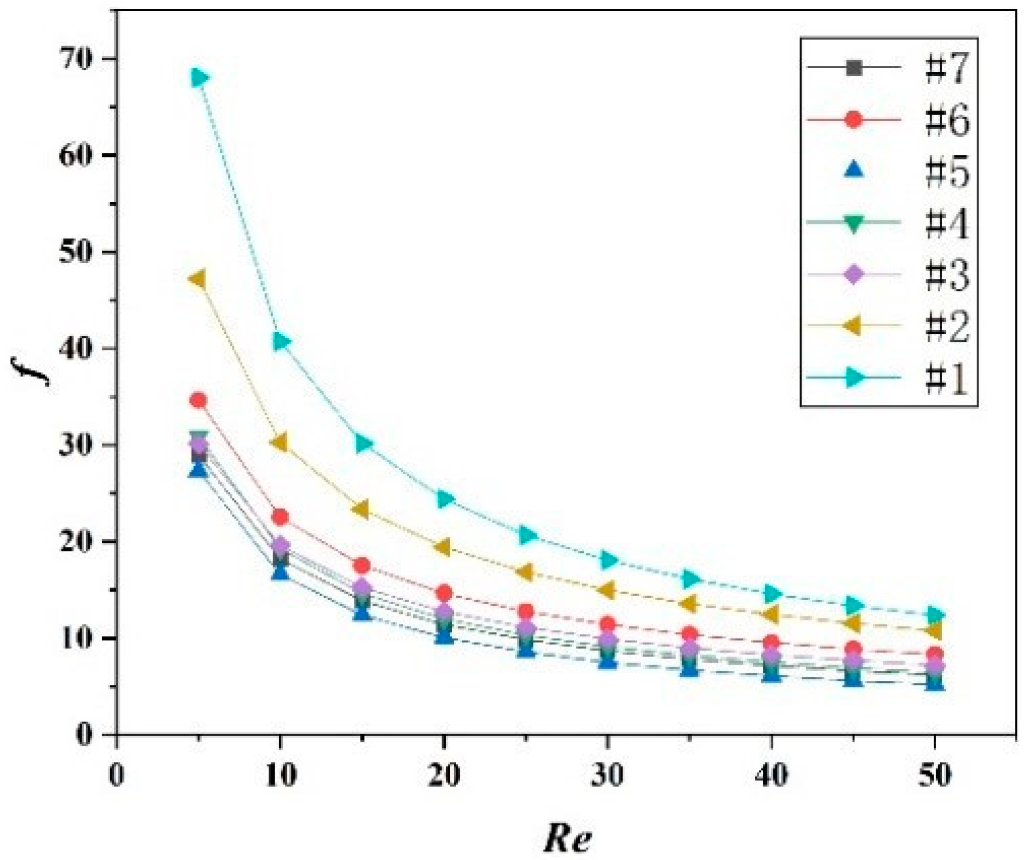
3. Experimental Results and Discussion

The effects of the #1 heat exchanger Re on the pressure drop at different temperatures are shown in Figure 2a. It is noticed that the pressure drops increase with Re and temperature. The effects of the #1 heat exchanger Re on the friction factor at different temperatures are shown in Figure 2b. It was obtained that the friction factors decrease with the increasing Re, and the three curves basically coincide, indicating that f is independent of temperature and is a single-valued function of Re. Among them, in the range of Re < 10, the rate of change of the friction factor is large, so the working condition of Re < 10 should be avoided in the actual project.
According to the most commonly used heat exchanger the f and Re relationship f = a * Re−b form of fitting is as follows, and the fitting curve is shown in Figure 3.
f = 223.92 R e 0.74
The fitting curve is shown in Figure 4 for seven types of heat exchangers, and the fitting formula is listed in Table 4.
Observing the coefficients of various formulas, it is found that the variation range of b is 0.62~0.74, the average value is 0.67, the fluctuation range is small, and the amplitude is 0.07; the variation range of a is 81.79~223.92, and the fluctuation range is large. In order to simplify the formula, the b value is fixed at an average of 0.67, leaving only the coefficient a as a variable, and then fitted again according to the form of f = a * Re−0.67. The fitting formula is listed in Table 5.
In Table 5, the error of f = a * Re−0.67 is slightly larger than f = a * Re−b, but it still meets the engineering requirements, indicating that the f = a * Re−0.67 fitting method is feasible.

4. Numerical Study

4.1. Physical Model

In order to investigate the influence of the three parameters of the corrugated angle β, the corrugated height h, and the corrugated spacing λ on the flow resistance characteristics of the chevron plate heat exchanger, a numerical simulation of the fluid field inside the B3-014 plate heat exchanger was carried out. Previously, the experimental research on working fluid BSE170 and the more viscous working fluid ISOVG320 was carried out. Under the conditions (temperature = 50 °C and q = 0.03 m3·h−1), experimental value: ΔPBSE170 = 9.13 kPa, ΔPISOVG320 = 16.38 kPa, and theoretical value: ΔPBSE170 = 0.236 kPa, ΔPISOVG320 = 3.38 kPa. The results show that the absolute error of pressure drop under ISOVG320 is about 1.5 times of that under BSE170. Compared with BSE170, the deviation of the pressure drop between the value calculated by the empirical formula and the experimental value is greater under ISOVG320. In order to better reveal the mechanism, this study uses the working fluid of high-viscosity fluid ISOVG320, three parameters are used as variables to simulate the chevron plate heat exchanger under constant flow conditions, and the effects of the three parameters on the flow resistance characteristics are analyzed according to the calculation results. The geometric structure and parameters (corrugated angle β, corrugated height h, and corrugated spacing λ) of the B3-014 plate heat exchanger are shown in Figure 5. The three parameters of B3-014 are β = 130°, h = 2 mm, and λ = 7.6 mm.

4.2. Governing Equation

The numerical investigations can be simplified with the following assumptions:
(1)
The working fluid is incompressible;
(2)
The heat transfer is steady;
(3)
The fluid flow is laminar, but the turbulent model was used in simulation for the turbulent state that may occur at a small part [18].
Based on the assumptions above, the governing equation is expressed as follows:
( v · ) v = f 1 ρ P + ν 2 v

4.3. Grid Generation and Independence Tests

The three-dimensional grid systems are generated by using the ICEM software (16.0, ANSYS, Canonsburg, PA, USA, 2015), as shown in Figure 6a. In order to show details of grid, zoom in view of meshing is shown in Figure 6b.
In consideration of the complexity of the flow field, unstructured tetrahedral elements are adopted to discretize the computational domain. Generally, the model with a larger mesh number can obtain more precise results at the expense of more computational workload. Therefore, it is necessary to select an appropriate mesh system in consideration of the balance. The calculation condition for grid independence study is shown in Table 6. The inlet and outlet are set as the velocity inlet and pressure outlet, respectively.
To guarantee the accuracy of numerical results, three grid systems (2.02 million with 20 nodes in the y direction, 6.6 million with 30 nodes, and 11 million elements with 40 nodes) are generated for the heat exchanger to carry out grid independence tests. The results of grid independence are listed in Table 7. The calculation deviation results using 6.6 and 11 million elements are less than 1%. Therefore, grid systems with 6.6 million elements are selected to perform the following simulations for the B3-014.

4.4. Boundary Conditions and Numerical Methods

The three-dimension, Semi-Implicit Method for Pressure Linked Equations is employed to conduct numerical simulations on the flow field inside of heat exchangers with the commercial software Fluent. Due to the presence of brazing joints in the plate heat exchanger, a local turbulence will be formed in the channel, which cannot be calculated by the laminar flow model. Therefore, in this study, the k-ε turbulence model was used to model the turbulence. The no-slip boundary condition is adopted on all solid surfaces, and the standard wall functions are used for the near wall region. The standard wall functions rely on the universal law of the wall, which basically states that the velocity distribution very near to a wall is similar for almost all turbulent flows. One of the most prominent parameters when judging the applicability of wall functions is the so-called dimensionless wall distance y+ denoted by:
y + = y u τ ν
where “uτ” is the so-called friction velocity, unit m/s; “y” is the absolute distance from the wall, unit m; and “ν” is the kinematic viscosity, unit m2/s.
According to the k-ε model 30 < y+ < 300, calculate the range of the grid height of the first layer, and y takes the maximum value. If the y+ obtained by the simulation is between 30–300, the height of the first layer grid meets the requirements. If not, halve the value of y until the value of y+ is between 30–300.
The working fluid is ISO VG320, whose thermo–physical properties depending on temperature are shown in Table 8.
The inlet and outlet are set as the velocity inlet and pressure outlet, respectively. The model inlet velocity value is calculated according to the model inlet flow shown in Table 9, and the corresponding turbulence intensity and hydraulic diameter are set according to the corresponding parameters.

4.5. Model Validation

In order to validate the reliability of numerical models and solution methods, the estimated results are compared with the experimental results of the B3-014 with the same working conditions, which are shown in Table 10.
The comparison results are shown in Figure 7. It can be seen from Figure 7 that the relationship of the simulation is consistent to the experimental result, and the deviation between the numerically and experimentally pressure differences is small, with a maximum deviation of about 11.4%.

5. Simulation Results and Discussion

In this section, we will discuss the simulation result of case 3 in Table 7.

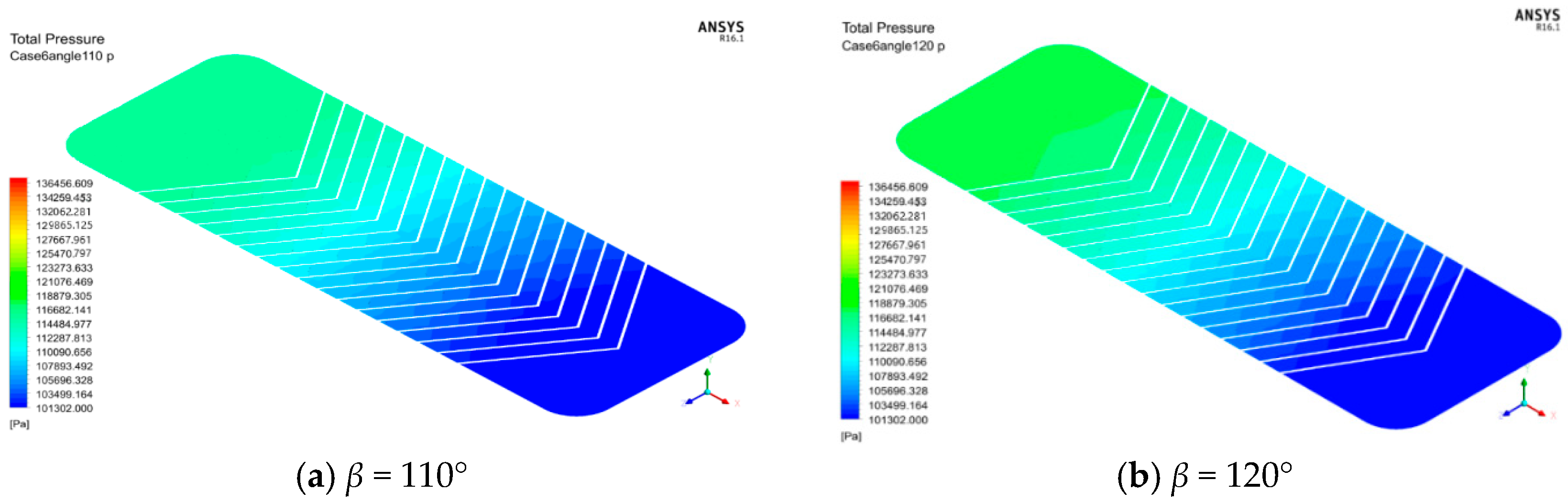
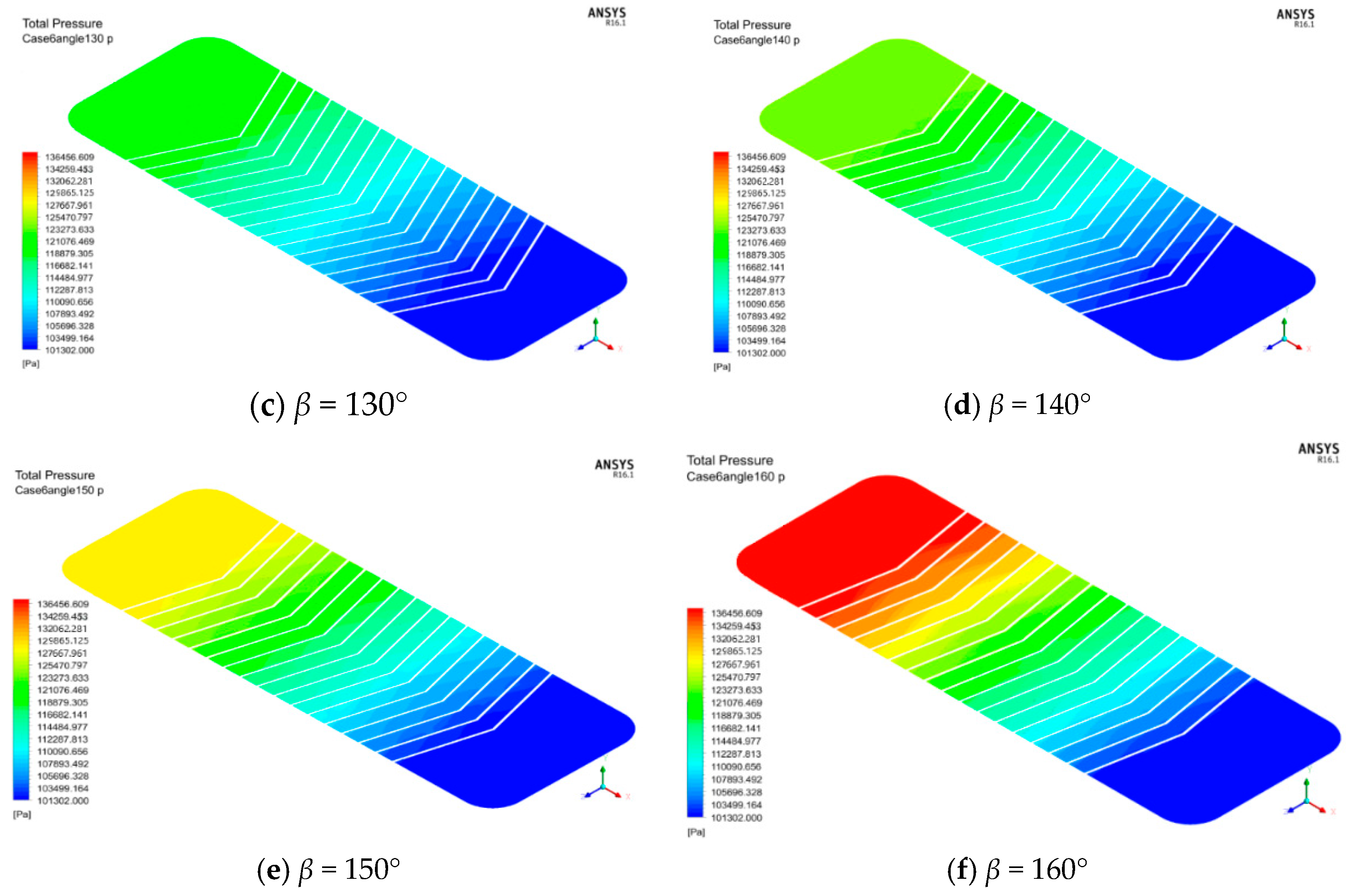
5.1. Effects of Corrugated Angle β

The effects of corrugated angle β on the pressure drop (h = 2 mm, λ = 7.6 mm) are shown in Figure 8. It is noticed that the pressure drop increases with the increasing corrugated angle. The pressure drop reaches the maximum when the corrugated angle is 160°. The pressure drop is a parameter that characterizes the resistance characteristics of fluid flow. In the B3-014 chevron plate heat exchanger, the tangential force of the plate on the fluid and the resistance of the contact to the fluid are the main reasons for the pressure drop. With the increase of the angle of the corrugation, the tangential force of the plate on the fluid and the resistance of the contact to the fluid increase. Therefore, in the range of the corrugated angle between 110 and 160°, the resistance of the flow increases when the corrugated angle is large and enlarged.
The pressure distribution charts when h = 2 mm, λ = 7.6 mm are shown in Figure 9a–f. It is noticed that the pressure values near the outlet area of the heat exchanger are all similar under the different angles. The high-pressure area increases and the inlet pressure increases with the increasing corrugated angle. Therefore, as far as the current simulated operating range is concerned, when the corrugated angle is small, the flow pressure drop can be reduced.
The speed distribution charts where the plate contacts are located when h = 2 mm, λ = 7.6 mm are shown in Figure 10a–f. It is noticed that as the corrugated angle increases, the number of contacts in the plate decreases, and the blue area where the vortex exists behind the contact also increases. As the corrugated angle gradually increases, the flow form becomes tortuous, and the fluid will reflect at the contact, causing the fluid to form a vortex behind the contact, and the diameter of the vortex increases with the increase of the angle of the corrugation.

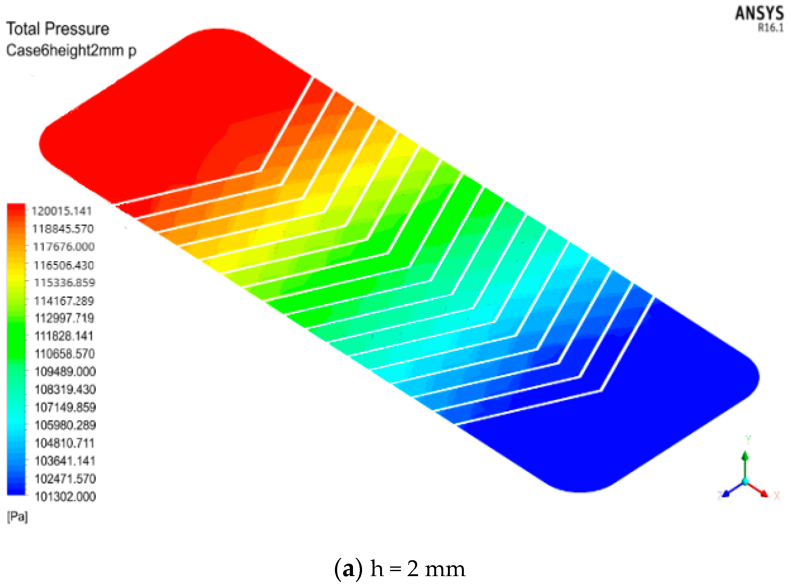
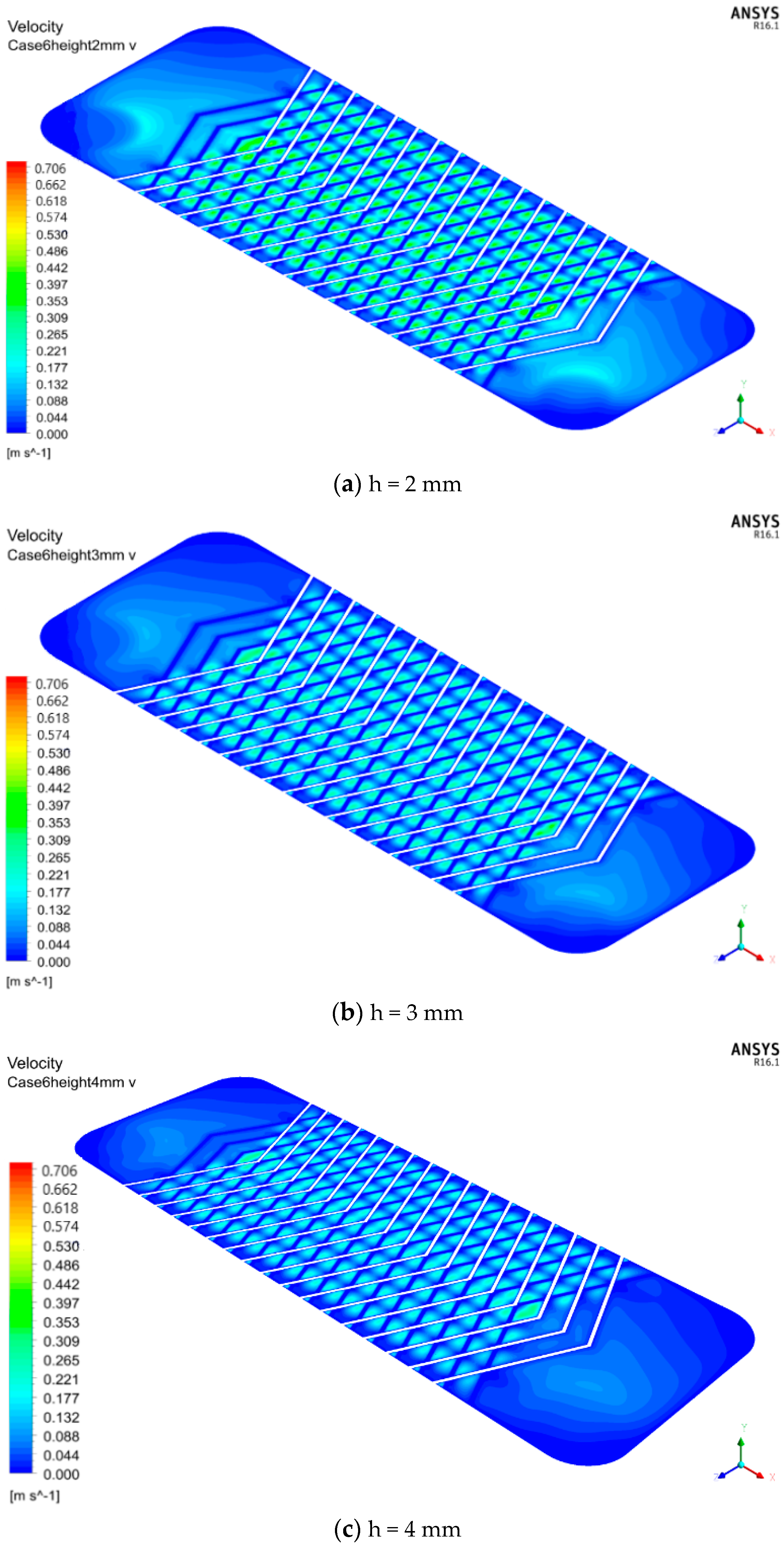
5.2. Effects of Corrugated Height h

The effects of corrugated height h on the pressure drop (β = 130°, λ = 7.6 mm) are shown in Figure 11. It is noticed that as the corrugated height increases, the pressure drop value gradually decreases. The pressure drops values at the inlet and outlet of the plate heat exchanger channels reflect the resistance characteristics of fluid flow. The tangential force of the plate in the heat exchanger channel on the fluid and the resistance of the contact to the fluid are the main reasons for the pressure drop. The tangential force of the plate on the fluid increases with the increasing corrugated height, the flow rate in the channel reduces the flow resistance.
The pressure distribution charts of the BPHE when β = 130°, λ = 7.6mm are shown in Figure 12a–c. It is noticed that the pressure gradually decreases along the flow direction. As the corrugated height increases, the pressure gradient near the contact gradually decreases, the tortuous flow gradually weakens, and the cross flow gradually enhances, and the influence of the contact on the fluid disturbance also weakens.
The speed distribution charts of the plate where the plate contacts are located when β = 130°, λ = 7.6 mm are shown in Figure 13a–c. It is noticed that with the increase of the corrugated height, the blue low-speed area behind the contact decreases; the proportion of the fluid occupied by the cross flow increases, and the tortuous fluid decreases, the smaller the disturbance effect of the contact on the fluid, and the smaller the vortex formed behind the contact. Therefore, as the corrugated height increases, the blue low-speed area behind the contact decreases. With the gradual increase of the corrugated height, the flow form changes into a tortuous flow. A single contact has a strong disturbance effect on the fluid, causing the fluid to form a vortex behind the contact. Therefore, the vortex generated is larger, and the velocity distribution becomes more and more uneven with the increasing corrugated angle.

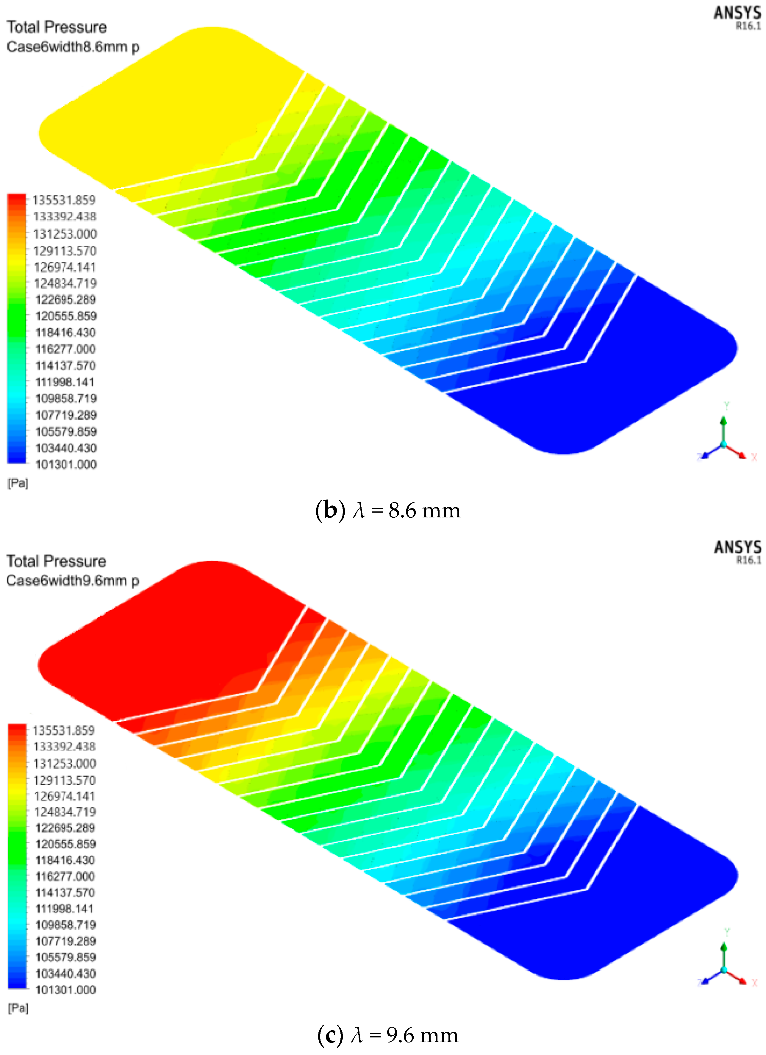
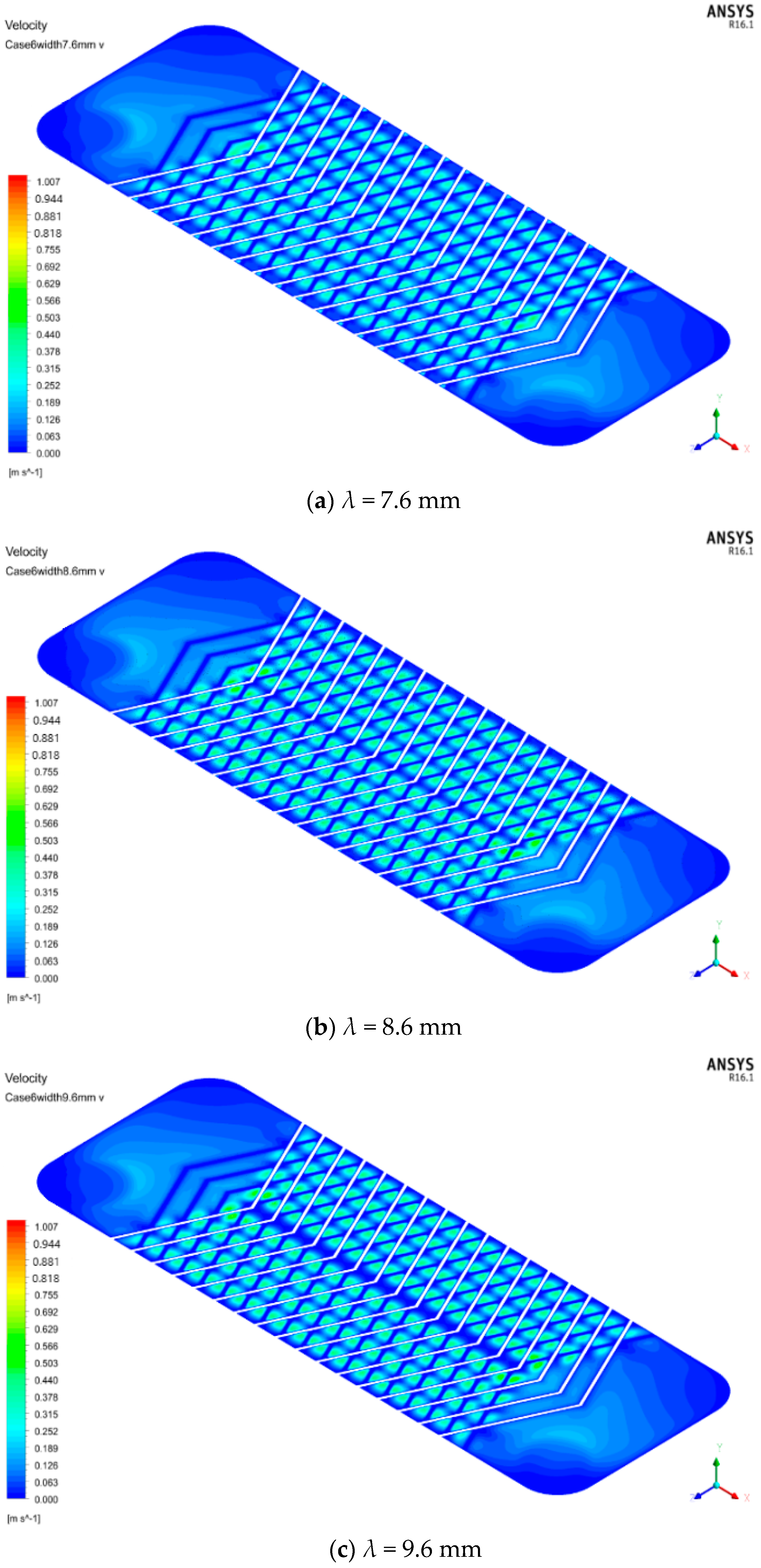
5.3. Effects of Corrugated Spacing λ

The effects of corrugated spacing λ on the pressure drop (β = 130°, h = 2 mm) are shown in Figure 14. It is noticed that the pressure drop value increases with the increasing corrugated spacing. The tangential force of the plates on the heat exchanger channels and the resistance of the contacts to the fluid are the main reasons for the pressure drop. With the corrugated spacing of increases, the number of contacts between the plates decreases and the vortex disturbance formed in the heat exchanger channel is enhanced, so the fluid flow resistance is increased.
The pressure distribution charts of the plate where the plate contacts are located when β = 130°, h = 2 mm are shown in Figure 15a–c. It is noticed that with the increase of the corrugated spacing, the area of the high-pressure area of the heat exchanger expands, and the inlet pressure rises, indicating that the expansion of the corrugated spacing will cause the deterioration of the flow state in the heat exchanger. It is noticed that near the inlet, change the corrugated spacing, the pressure significantly changes, indicating that with the larger corrugated spacing, we must pay close attention to the pressure capacity of the heat exchanger inlet design; near the outlet, change the corrugated spacing, the pressure distribution of the heater has no obvious effect, and the pressure shock is also weaker.
The speed distribution charts of the plate where the plate contacts are located when β = 130°, h = 2 mm is shown in Figure 16a–c. It is noticed that as the corrugated spacing increases, the number of contacts decreases, the velocity field distribution becomes more and more uneven, and the diameter of the blue area where the flow rate is relatively low behind the contacts also increases. The blue area behind the contact is the vortex area in the flow field. When the corrugated spacing is relatively small, the cross flow in the fluid accounts for a large proportion, the contacts have less disturbance to the fluid, and the vortex is small.

6. Conclusions

The hydraulic performance of the BPHEs were investigated through an experiment and the results were further explained by simulation. The major conclusions are shown below:
(1)
The pressure drops of BPHEs increase with Reynolds number and the temperature. The friction factor of BPHEs decreases with Re number, but could not be influenced by the temperature.
(2)
The relationship between friction factor and Reynolds number, with a range from 5 to 50, could be shown as f = a R e 0.67 .
(3)
The flow resistance gradually increases with the increasing corrugated angle and increasing corrugated spacing, decreases with the increasing corrugated height.
(4)
The flow resistance reduces with the increasing corrugated height. The expansion of the corrugated spacing will lead to the deterioration of the flow state in the heat exchanger. The optimal parameters are the corrugated angle β = 110°, the corrugated height h = 4 mm, and the corrugated spacing λ = 7.6 mm.

Author Contributions

Y.Z. (Yi Zhong), K.D., S.Z., J.H., Y.Z. (Yingjie Zhong), Q.L., Z.W., Z.L. and Q.W. contributed to the design and implementation of the research, to the analysis of the results, and to the writing of the manuscript. All authors have read and agreed to the published version of the manuscript.

Funding

This research was supported by the Natural Science Foundation of Zhejiang Province under Grant No.LY18E060012 and the National Natural Science Foundation of China under Grant No.51106139.

Acknowledgments

Thanks to the reviewers and editor for manuscript improvements.

Conflicts of Interest

The authors declare no conflict of interest.

References

  1. Würfel, R.; Ostrowski, N. Experimental investigations of heat transfer and pressure drop during the condensation process within plate heat exchangers of the herringbone-type. Int. J. Therm. Sci. 2004, 43, 59–68. [Google Scholar] [CrossRef]
  2. Bayraktar, I.; Islamoglu, Y.; Parmaksizoğlu, C.; Durmaz, T. Heat transfer characteristics between sinusoidal wavy plates. In Proceedings of the 36th AIAA Thermophysics Conference, Orlando, FL, USA, 22–26 June 2003. [Google Scholar]
  3. Kim, M.B.; Park, C.Y. An experimental study on single phase convection heat transfer and pressure drop in two brazed plate heat exchangers with different chevron shapes and hydraulic diameters. J. Mech. Sci. Technol. 2017, 31, 2559–2571. [Google Scholar] [CrossRef]
  4. Khan, T.; Khan, M.; Chyu, M.-C.; Ayub, Z. Experimental investigation of single phase convective heat transfer coefficient in a corrugated plate heat exchanger for multiple plate configurations. Appl. Therm. Eng. 2010, 30, 1058–1065. [Google Scholar] [CrossRef]
  5. Lee, K.-S.; Kim, W.-S.; Si, J.-M. Optimal shape and arrangement of staggered pins in the channel of a plate heat exchanger. Int. J. Heat Mass Transf. 2001, 44, 3223–3231. [Google Scholar] [CrossRef]
  6. Hou, T.; Chen, Y. Pressure drop and heat transfer performance of microchannel heat exchanger with different reentrant cavities. Chem. Eng. Process. Process. Intensif. 2020, 153, 107931. [Google Scholar] [CrossRef]
  7. Lee, Y.N. Heat transfer and pressure drop characteristics of an assembly of partially segmented plates. J. Heat Transf. 1989, 111, 44–50. [Google Scholar] [CrossRef]
  8. Zhou, M.L. Experimental and theoretical study on the flow distribution of plate heat exchanger. J. North. JiaoTong Univ. 2001, 25, 67–71. [Google Scholar]
  9. Ma, X.H. Experimental investigation and thermodynamic analysis of performance of plate heat exchanger for low Reynolds number. J. Therm. Sci. Technol. 2007, 6, 42–48. [Google Scholar]
  10. Li, J.J. Research on Heat Transfer and Pressure Drop in Low Reynolds Number Flow Heat Exchangers; Shanghai Jiao Tong University: Shanghai, China, 2004. [Google Scholar]
  11. Li, J.J.; Chen, J.P.; Chen, Z.J. Experimental study of heat transfer and pressure drop characteristics of the offset strip fin in low Reynolds number. Energy Technol. 2004, 25, 147–149. [Google Scholar]
  12. Li, Q.Y. Research and Calculation Software Writing for Chevron Bphe under Low Reynolds Number; Zhejiang University of Technology: Hangzhou, China, 2019. [Google Scholar]
  13. Wu, Z.N. The Study of the Pressure Drop Characteristics of Plate Heat Exchanger under Low Reynolds Number; Zhejiang University of Technology: Hangzhou, China, 2017. [Google Scholar]
  14. Xia, C.W. The Experiment and Simulation of the Pulsating Flow of a Small Channel Plate Type Plate Heat Exchanger; Zhejiang University of Technology: Hangzhou, China, 2018. [Google Scholar]
  15. Jiao, A.N.; Li, Y.Z.; Zhang, R. Effects of different inlet angles on distributor performance. J. Chem. Ind. Eng. 2001, 52, 11–15. [Google Scholar]
  16. Jiao, A.N.; Li, Y.Z.; Zhang, R. Flow distribution performance of different distributor’s configuration in plate-fin heat exchanger. Xi’an Jiaotong Univ. Xuebao 2001, 52, 11–15. [Google Scholar]
  17. Shi, Y.N.; Feng, L.L.; Du, X.Z. Experimental study on heat transfer and flow characteristics of v corrugated plate heat exchanger. Mod. Electr. Power 2008, 25, 60–63. [Google Scholar]
  18. Galeazzo, F.C.C.; Miura, R.Y.; Gut, J.; Tadini, C. Experimental and numerical heat transfer in a plate heat exchanger. Chem. Eng. Sci. 2006, 61, 7133–7138. [Google Scholar] [CrossRef]
  19. Gut, J.; Pinto, J.M. Optimal configuration design for plate heat exchangers. Int. J. Heat Mass Transf. 2004, 47, 4833–4848. [Google Scholar] [CrossRef]
  20. Gut, J.; Pinto, J.M. Modeling of plate heat exchangers with generalized configurations. Int. J. Heat Mass Transf. 2003, 46, 2571–2585. [Google Scholar] [CrossRef]
  21. Gherasim, I.; Galanis, N.; Nguyen, C.T. Effects of smooth longitudinal passages and port configuration on the flow and thermal fields in a plate heat exchanger. Appl. Therm. Eng. 2011, 31, 4113–4124. [Google Scholar] [CrossRef]
  22. Gherasim, I.; Galanis, N.; Nguyen, C.T. Heat transfer and fluid flow in a plate heat exchanger. Part II: Assessment of laminar and two-equation turbulent models. Int. J. Therm. Sci. 2011, 50, 1499–1511. [Google Scholar] [CrossRef]
  23. Gherasim, I.; Taws, M.; Galanis, N.; Nguyen, C.T. Heat transfer and fluid flow in a plate heat exchanger part I. Experimental investigation. Int. J. Therm. Sci. 2011, 50, 1492–1498. [Google Scholar] [CrossRef]
  24. Mehrabian, M.; Poulter, R. Hydrodynamics and thermal characteristics of corrugated channels: Computational approach. Appl. Math. Model. 2000, 24, 343–364. [Google Scholar] [CrossRef]
  25. Neagu, A.A.; Koncsag, C.; Barbulescu, A.; Botez, E. Estimation of pressure drop in gasket plate heat exchangers. Ovidius Univ. Ann. Chem. 2016, 27, 62–72. [Google Scholar] [CrossRef] [Green Version]
Figure 1. Experimental device diagram.
Processes 08 01076 g001
Figure 2. Variation of Δp and f with Re for #1: (a) Δp changes with Re; (b) f changes with Re.
Processes 08 01076 g002
Figure 3. Fitting relationship of the #1 plate type between f and Re.
Processes 08 01076 g003
Figure 4. Trend graph of each fitting formula.
Processes 08 01076 g004
Figure 5. Geometric structure of chevron plate.
Processes 08 01076 g005
Figure 6. Flow domain meshing (6.6 million elements): (a) overall meshing; (b) zoom in view.
Processes 08 01076 g006
Figure 7. Comparison of simulated and experimental pressure drop under ISOVG320.
Processes 08 01076 g007
Figure 8. Pressure drops versus corrugated angles.
Processes 08 01076 g008
Figure 9. Pressure distribution when h = 2 mm, λ = 7.6 mm: (a) corrugated angle with 110°; (b) corrugated angle with 120°; (c) corrugated angle with 130°; (d) corrugated angle with 140°; (e) corrugated angle with 150°; (f) corrugated angle with 160°.
Processes 08 01076 g009aProcesses 08 01076 g009b
Figure 10. Speed distribution when h = 2 mm, λ = 7.6 mm: (a) corrugated angle with 110°; (b) corrugated angle with 120°; (c) corrugated angle with 130°; (d) corrugated angle with 140°; (e) corrugated angle with 150°; (f) corrugated angle with 160°.
Processes 08 01076 g010aProcesses 08 01076 g010b
Figure 11. Pressure drops versus corrugated heights.
Processes 08 01076 g011
Figure 12. Pressure distribution when β = 130°, λ = 7.6 mm: (a) corrugated height with 2 mm; (b) corrugated height with 3 mm; (c) corrugated height with 4 mm.
Processes 08 01076 g012aProcesses 08 01076 g012b
Figure 13. Speed distribution when β = 130°, λ = 7.6 mm: (a) corrugated height with 2 mm; (b) corrugated height with 3 mm; (c) corrugated height with 4 mm.
Processes 08 01076 g013
Figure 14. Pressure drops versus corrugated spacing.
Processes 08 01076 g014
Figure 15. Pressure distribution when β = 130°, h = 2 mm: (a) corrugated spacing with 7.6 mm; (b) corrugated spacing with 8.6 mm; (c) corrugated spacing with 9.6 mm.
Processes 08 01076 g015aProcesses 08 01076 g015b
Figure 16. Speed distribution when β = 130°, h = 2 mm: (a) corrugated spacing with 7.6 mm; (b) corrugated spacing with 8.6 mm; (c) corrugated spacing with 9.6 mm.
Processes 08 01076 g016
Table 1. Parameters of the MIK MIKD-LC-A series oval gear flowmeter.
Product ModelRange/(m3/h)Nominal Pressure/MPaUncertainty
MIKD-LC-A-DN150.3~1.51.6±0.2%
MIKD-LC-A-DN251.2~61.6±0.2%
Table 2. Important geometric parameters of the chevron brazed heat exchanger plate.
NumberEquivalent Diameter de/mmChannel Cross-Sectional Area Asec/mm2Import and Export Distance L/mmSingle Plate Effective Heat Exchange Area A/mm2
#14.1138.661720.014
#242002500.027
#342004660.052
#44315.125190.095
#54.9435.0225190.095
#64.8761.556280.21
#74.8847.26190.26
Table 3. Physical properties of BSE170 working fluid.
Temperature/°CDynamic Viscosity/(Pa·s)Density/(kg/m3)
50100951
6062944
7042937
Table 4. Summary of fitting results for each plate type according to f = a * Re−b.
TypeFitting FormulaScopeSum of Squared Residuals
#1f = 223.92 * Re−0.745 < Re < 301347.05
#2f = 132.3 * Re−0.645 < Re < 25281.85
#3f = 81.79 * Re−0.625 < Re < 45804.21
#4f = 92.33 * Re−0.685 < Re < 4560.98
#5f = 87.15 * Re−0.725 < Re < 4098.41
#6f = 94 * Re−0.625 < Re < 25285.97
#7f = 85.16 * Re−0.675 < Re < 35100.95
Table 5. Summary of fitting results for each plate type according to f = a * Re−0.67.
TypeFitting FormulaScopeSum of Squared Residuals
#1f = 195.18 * Re−0.675 < Re < 30200.57
#2f = 141.38 * Re−0.675 < Re < 25375.57
#3f = 96.66 * Re−0.675 < Re < 4514.07
#4f = 89.67 * Re−0.675 < Re < 4585.83
#5f = 78.16 * Re−0.675 < Re < 4023.04
#6f = 105.8 * Re−0.675 < Re < 2535.17
#7f = 85.16 * Re−0.675 < Re < 35100.95
Table 6. Calculation condition for grid independence study.
Temperature/°CDensity
/kg·m3
Dynamic Viscosity
/Pa·s
Specific Heat Capacity
/kJ·(kg·°C)
Thermal Conductivity
/W·(m∙°C)
Inlet Flow
/m3·h−1
Outlet Pressure
/MPa
508780.1510891.9460.1450.030.06
Table 7. Grid independence test.
Number of Elements/MillionsΔP/kPa
2.0214.67
6.616.22
1116.25
Table 8. Thermo–physical properties of ISO VG320.
Temperature/
°C
Dynamic Viscosity/
mPa·s
Specific Heat Capacity/
kJ·(kg·°C)−1
Density/
kg·m−3
50151.089 1.946 878
6090.786 1.982 872
7057.800 2.020 866
Table 9. Calculating conditions of B3-014 heat exchanger pressure drop.
Working
Condition
Temperature
/°C
Density
/kg·m3
Dynamic Viscosity
/Pa·s
Specific Heat Capacity
/kJ·(kg·°C)
Thermal Conductivity
/W·(m∙°C)
Inlet Flow
/m3·h−1
Outlet Pressure
/MPa
1608720.0907861.9820.1450.060.1
2608720.0907861.9820.1450.180.1
3608720.0907861.9820.1450.30.1
Table 10. Heat exchanger B3-014H experimental data under 50 °C under ISOVG320.
Q/m3·h−1q/m3·h−1u/m·s−1ReΔp/kPaf
0.300.030.061.4316.38246.20
0.400.040.081.9119.72166.77
0.500.050.102.3924.40132.03
0.600.060.122.8630.05112.92
0.700.070.143.3434.5795.45
0.800.080.163.8239.4183.32
0.900.090.184.3044.6874.63
1.000.100.204.7750.6568.53
1.100.110.225.2554.7761.24
1.200.120.245.7362.3258.55
1.300.130.266.2168.4354.79

