
Soap Film Visualization of a 10 cm-Span Flapping Wing


Department of Mechanical and Electromechanical Engineering, Tamkang University, New Taipei 251301, Taiwan
*
Author to whom correspondence should be addressed.
Fluids 2021, 6(10), 361; https://0-doi-org.brum.beds.ac.uk/10.3390/fluids6100361
Submission received: 3 September 2021
/
Revised: 1 October 2021
/
Accepted: 5 October 2021
/
Published: 12 October 2021
(This article belongs to the Special Issue Advances in Biological Flows and Biomimetics, Volume II)
Abstract
:Flapping wing micro-air-vehicles (FWMAVs) animate the small-space dexterous flight, hovering, and energy-saving characteristics of birds and insects, and are believed to have enlightenment for the development of bionic flight in the future. When designing FWMAVs, detailed unsteady aerodynamic information is required. Besides the computational fluid mechanics (CFD) technology study, the flow visualization is also needed to assist this research. This article innovatively used soap film visualization with high-speed photography to record two kinds of the 2D flow fields laterally and longitudinally, respectively, generated by a flapping wing of 10 cm span. Different from the qualitative comparison of soap film imaging with the conventional smoke tracing method, the subsequent processing of the soap film images was demonstrated. This work explains how to quantify the soap film imaging into lift and thrust forces, and the corresponding results are compared with the wind tunnel force measurement data preliminarily.
1. Introduction
Flapping wing micro-air-vehicles (FWMAVs) or ornithopters has certain advantages such as low-speed cruising, high operational and power efficiency. It excels in hovering [1,2,3,4], low-speed flight, narrow-space movement [5], short-field take-off and landing [6]. They can be deployed in indoor and outdoor for its flexible action, timely obstacle avoiding, low-speed navigation, quickly switch between forward flight and hovering. For enhancing the aerodynamic performance, many research topics varied the upswing requirements such as the angle of attack (AOA), wingtip trajectory [7,8], wing area, flapping frequency, feather direction [9,10,11], etc. As flow visualization analysis is important to understand the unsteady aerodynamics and the design optimization of FWMAVs, therefore, how to develop the flow visualization technique to investigate the unsteady flow feature of flapping wings is one of the crucial issues that should be taken into consideration.
Conventional smoke tracing method is widely used for various flow visualization experiments on air vehicles. By using laser slicing technique, two-dimensional (2D) flow pictures were obtained from the real three-dimensional (3D) flow field. One drawback of the above-mentioned experiment may be its qualitative feature which is not easy to calculate the corresponding aerodynamic force values [12,13].
Pressure-sensitive painting (PSP) technique demonstrates the high-resolution pressure distribution on the wing or body surface of aircraft in a quantitative manner. The pressure field on wing surface is taken as an integral to a global resultant force applied on the wing [14,15,16]. However, high resolution of PSP is only rich in the spatial domain using a high-bit camera, but not in the time domain. There exist difficulties in taking high-bit images of the flapping wing surfaces with high wingbeat frequency.
Regarding the quantitative flow visualization, majority of the works used particle image velocimetry (PIV) with high-speed photography to measure the unsteady flow fields including the flapping wing case [17,18].
This paper aims to investigate the 2D flow field around a 10 cm-wingspan FWMAV by interacting with the soap films along the longitudinal and lateral directions, respectively. In the past, soap film is used to visualize the steady state flow patterns induced by a stationary cylinder or other 2D objects [19,20,21,22,23,24,25,26,27]. The observation is only categorized as one of the qualitative methods, similar to the smoke tracing. For modifying the soap film visualization to a quantitative method, the relationship between the color (soap film thickness) fields and the corresponding thrust and lift induced by the flapping wing are firstly derived, and later verified using image processing with the experimental results in this work. The developed technique is shown to record the unsteady lift behavior of a flapping wing in a quantitative manner with low cost and without any dangerous concern.
2. Aerodynamic Force Formulation of a FWMAV across a Soap Film
Consider an infinitesimal element or a control volume with width and height of dy, dz, and an instantaneous film thickness h(y, z; t) on the soap films with three cases in Figure 1. These three cases correspond to different orientations of soap films perpendicular to its starboard direction (Figure 1a), freestream direction (Figure 1b) and vertical direction (Figure 1c) of a FWMAV with a traveling speed .
We outlined the pros and cons of these three cases of soap films in Table 1 and only adopted the two feasible soap films Figure 1a,b to investigate the thrust and lift forces of the FWMAV. The soap film of Figure 1c is apparently broken by the flapping wing tips immediately and not possible to be realized herein.
The volume of the element is dy × dz × h(y, z; t). We also assume the soap film is incompressible. Therefore, the amounts of inflow and outflow affect the thickness of the soap film. The relationship between the thickness and flow velocities of the soap film is governed by the mass conservation law as below.
Taking the Taylor’s expansion of v(y + dy, z) and w(y, z + dz) at the point of (y, z), the in-homogeneous continuity equation for the soap film thickness h is as below.
where (v, w) is the 2D velocity field of the soap film. In general, after solving (v, w), we can obtain the pressure field and calculate the resultant lift and drag (negative thrust).
The mass conservation can be expressed by Gauss theorem, Equation (3) [28].
where . Substitute the of Equation (2) and dV into the right-hand-side of Equation (3) and obtain Equation (4).
The practical use of Equation (4) is that we just block around the wing with soap film area S = A and integral the time-rate of thickness h according to Equation (4). The block we are interested in is assumed to have width y* and height z*, or A = (y*) × (z*).
2.1. FWMAV Travels along the Soap Film Perpendicular to the Starboard Direction
As in Figure 1a, assume no velocity at surfaces ② and ③, but the average jet speed passes over the surface ① and the downwash speed flows over the surface ④. Flow rates at surfaces ⑤ and ⑥ cancel to each other; the left-hand side of Equation (4) becomes:
The thrust is defined as the momentum time rate along the y-direction:
The lift is defined as the momentum time rate along the z-direction:
From Equations (7) and (8), the thrust T and lift L cannot directly be decoupled and derived from the soap film thickness matrix summation in Equation (6). We, therefore, look for solving the lift L from the other direction of soap film experiment which will be conducted in the next step.
2.2. FWMAV Penetrating the Soap Film Perpendicular to the Freestream Direction
As in Figure 1b, assume no velocity at surfaces ①, ②, and ③; only passes over the surface ④. Flow rates at surfaces ⑤ and ⑥ cancel to each other; the left-hand side of Equation (4) becomes:
Again, the lift is defined as the momentum time rate along the z-direction:
From Equation (11), the lift L can be directly derived from the soap film thickness matrix in Equation (10). The magnitude of the lift L is to have a higher order than the soap film thickness h and can be regarded as a 3D lift for comparison in the followings.
After solving the lift, we would rather reconsider Equation (6) and solve the horizontal jet speed by substituting downwash of Equation (10) into Equation (6).
Thus, the thrust T in Equation (7) can be re-written by equating the jet speed of Equation (12) and by inserting the downwash of Equation (10).
Two systems in Equation (13) come from two soap films subject to the Section 2.1 and Section 2.2. For reasonable interpretation, the thickness fields of the soap film color fringes of Figure 1a,b should be with the same amount of color pixels and the same rectangular domain size.
We cut and analyze a 2D slice from the actual 3D flow field about thrust force. Equation (13) can be multiplied with a factor of (wingspan/h0) to obtain a quasi-3D thrust with the same order magnitude of a 3D lift.
3. Materials and Methods
Soap film may be the cheapest way to observe 2D flow fields. The subtle vortex pattern on the soap film can be observed through its color fringes. In the traditional soap film water tunnel, in order to avoid the soap film breaking, a soap film fall of about 0.1 m × 3 m was installed and replenished stably through the pumping motor to provide a longer time for observing soap film [19,20,21,22,23,24,25,26,27]. Because of the width limitation, after deducting the boundary area, it is suitable for observing the flow field around a body of millimeter scale. Therefore, the traditional soap film water tunnel performs well to measure vortex patterns under the conditions of low speed, low frequency, and small amplitude.
Firstly, this experimental work is prepared to improve the soap film stretching frame which in turn extends the observation window up to centimeter scale. The total width for measurement could reach to 25 cm, which is convenient for observing the flow field generated by a flapping wing of 10 cm span. The time-changing observation made from the soap film color fringe is recorded by high-speed CCD.
Secondly, as described in Section 2, the authors quantitatively formulated the mass conservation on the soap film and derived the streamwise jet speed or downwash speed respectively in terms of the time changing of film thickness. The jet speed and downwash were expected to evaluate the unsteady thrust force and the lift force of a flapping wing to travel along the soap film or to penetrate the soap film. For preliminarily conversion of the color field into the soap film thickness field, we can resort to the available program such as MATLAB.
The following information are about the materials and setup for the soap film experiment in this work:
3.1. Soap Film Frame
The wingspan of the FWMAV in this study is taken as 10 cm. The size of the soap film and its PMMA (acrylic) frame is therefore designed with a length of 50 cm and a height of 25 cm to prolong the sustention time for the soap film. For avoiding the velocity interference from the boundary edges, there is no mass in-and-out (Neumann boundary condition) at the frame. PMMA material is inert and stable to the soap film solution. The PMMA frame is cut by laser as one piece without any voids and sharp edges.
3.2. Soap Film Solution
The soap film solution contains complex ingredients including surfactant, glycerol, honey and acetic acid in the 7:1:1:1 ratio. In general, surfactant creates the soap film; glycerol sustains the soap film longer; honey increases viscosity to prevent against the gravitation thinning; acetic acid adjusts the solution polarity.
The water molecules in the soap film will subside downward and cause the upper film thinner until collapsing. Therefore, the soap film can be only sustained for a certain moment. The authors have ever tried many recipes to prolong the sustention time more than 10 min but the solution quality is not stable and finally searched for the commercial bubble solution available in the market (www.unclebubble.com.tw accessed on 3 September 2021). The commercial surfactant composition is confidential but stable. In this work, the soap film generated by the commercial bubble solution compromises the sustention time to 2 min in our soap film frame and the saturation in color hues is good to our flow visualization experiment. The sedimentation downward speed can be measured from the un-stimulated soap film during the sustention time and was evaluated as about 0.25 cm/s, much smaller than the downwash with the magnitude at approximately 50 cm/s in this work. The soap film solution is almost temperature-independent during 10–30 °C.
3.3. High-Speed Camera
The flapping frequency of the FWMAV in this work is near to 28–38 Hz. We need a high-speed camera (Phantom Miro EX4, Vision Research, Wayne, New Jersey, USA) capable of recording the detailed flow feature for at least one flapping cycle. This camera has its control software of phantom camera control (PCC) to setup the image capture speed, time duration, trigger mode, and file transfer. The image frame of the camera setting is the pixel numbers 800 × 600, frame per second (fps) is 1000 herein.
3.4. Background Lighting
Soap film experiment in this work is to quantify the thickness field of soap film. Therefore, the light reflection from the background should be avoided as much as we can. Selecting a black velvet as the background is necessary.
According to two kinds of soap films in Figure 1 for measuring thrust and lift, there are two setups of background lighting. The first setup in Figure 2a,b is for the FWMAV to travel along the streamwise direction. The frontside of the soap film is an expandable polystyrene (EPS) wall as the light diffuser to scatter the white light from the lateral light source. The topside and the lateral sides were also shielded by EPS as well to ensure the uniform light intensity for the soap film. The image window in Figure 1 is quite long due to the travel distance of FWMAV and the overall light intensity for color images on soap film is consequently not strong enough. The highest allowable travel speed of FWMAV is about 1.5 m/s.
The second setup in Figure 2c,d is for the FWMAV to penetrate the soap film. An EPS semi-sphere with the diameter of 45 cm is used and can confines the white light from the light bulb inside the EPS chamber. Therefore, the light intensity is better than the first setup. For installing the camera, a 7 cm-diameter window circle is made to have good images of soap film. The drawback of this second setup is that the travelled distance is short and the allowed travel speed of FWMAV is only 0.1–0.2 m/s, much slower than the first setup.
3.5. FWMAV
The 10 cm-span FWMAV used in this work is shown in Figure 3a and the dimension and shape of the flapping wing are shown in Figure 3b. The flapping mechanism is a four-bar linkage with a gear reduction module [7,8,10,11]. The wing and fuselage frame are made by carbon fibers and EPS. The total body mass is 4.28 g and can fly for 9 s by the flapping frequency of 28–38 Hz and the flying speed of 1–2 m/s. The wind tunnel data of Refs. [29,30,31] could be referred to the lift or thrust force comparison about the soap film experiment result in this work.
3.6. Experiment Sequence
The experimental setup of the soap film visualization for a FWMAV is shown in Figure 4.
4. Results
By the agitation and disturbances from the flapping wing, the sustaining time of soap films shortens to several seconds. However, this short duration of several seconds is enough to capture many flapping cycles for image processing and force analysis.
4.1. FWMAV Travels along the Soap Film Perpendicular to the Starboard Direction
The authors’ group initially studied and collected the soap film images of a flapping wing according to Section 2.1 and the experimental setup in Figure 2a,b [28,31]. One case with the traveling speed, inclined angle and flapping frequency of the FWMAV of 1.16 m/s, 20° and 20.8 Hz, respectively, is shown in Figure 5. The inverted Karman vortex pattern for generating the thrust force is clearly shown on the soap film and moves in downstream direction. The intercepting plane of the soap film on the flapping wing is along the quarter chord very near to the mean aerodynamic chord which could generally resemble the flow characteristics of the whole wing [32].
4.2. FWMAV Penetrating the Soap Film Perpendicular to the Freestream Direction
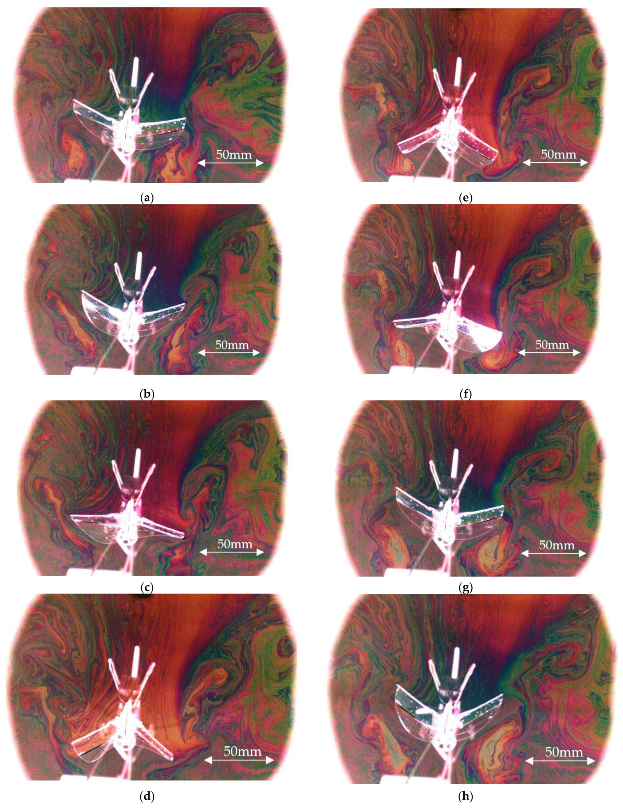
The authors continued to collect the soap film images of a flapping wing along the spanwise direction by using the experiment setup in Figure 2c,d [28]. One case with the penetrating speed, inclined angle and flapping frequency of the FWMAV as 0.15 m/s, 20° and 7.58 Hz, respectively, is shown in Figure 6. The wingtip vortex pattern for generating the induced drag and the downwash is clearly shown on the soap film and propagates spanwise according to the flapping motion in a qualitative manner. The above figures undergo the image processing procedure as shown in Figure 7.
4.3. Image Processing
Figure 7 represents the flow chart for image processing of the soap film visualization. First of all, we use the MATLAB software to read the color field of the soap film. In MATLAB, the color field can be interpreted as different formats in RGB, HSV or YCrCb (YUV). In this work, we adopted the “RGB” format with 0–255 resolution for each base color. One (R, G, B) coordinate denotes one distinct color for each pixel on the soap film. For example, (0, 0, 0) denotes all black; (255, 255, 255) denotes all white; (255, 0, 0) denotes all red, etc. The command of ”imread” is used to perform the above color reading and we save one color matrix for one image frame.
Secondly, we performed the image processing by reading a given standard color template (http://markkness.net/colorpy/ColorPy.html accessed on 3 September 2021) and save it as the color spectrum. The standard color template is composed of 512 different colors with their thickness from 0 nm to 1000 nm individually. This color spectrum vs. thickness of the color template is referred for comparing and distinguishing the local thickness of each color pixel on the soap film and is what we called the color-thickness transformation. That is to find the closest color matched for each color pixel using the least mean square error, to assign each pixel with its corresponding thickness, and to store the thickness matrix or the wavelength matrix for each N-th frame image. If the film thickness is higher than 1000 nm which actually means this local spot of the soap film is transparent, then we ignore these color pixels.
Take the example of Figure 8a, we selected a full set of N image frames for one flapping cycle. Before the color-thickness transformation, many image noises including the FWMAV wing frame, fuselage, supporting stand and the PMMA frame should be all identified as all-black color and zero thickness from the original images. Therefore, we moreover define the most interested rectangular area as the N-th frame in Figure 8a for performing the color-thickness transformation. The wavelength or thickness matrix of the colorful N-th frame Figure 8a is shown as the grey-scale plot with thickness range of 0–900 nm in Figure 8b.
4.4. Force Comparison
For calculating the thrust T and lift L of the FWMAV, the previous two kinds of thickness matrix in Section 2.1 and Section 2.2 should be summed as Equations (11) and (13). The time rate in Equations (11) and (13) means that we need two successive image frames and their summation to perform the time derivative as one jet speed or one downwash speed . For example, the flapping frequency is 7.58 Hz in Figure 6. There are 132 image frames for one flapping cycle if Δt = 1 ms for two successive images in Equation (11). Figure 9a,b shows one-cycle of the lift and thrust come from the soap film experimental images of Figure 5 and Figure 6.
The raw waveforms of the one-cycle thrust, and lift were rich of ripples noise which is apparently observed in Figure 5. This noise is due to the free-surface wave propagation on the soap film which is agitated by the flapping wing. After filtering the wave propagation ripples in Figure 9a,b, the more purified signals are obtained. They are similar to the classical wind-tunnel signals of lift and thrust in Figure 9c,d.
The classical lift and thrust signals of the FWMAV are from a blow-down wind tunnel testing. The length and cross section area of the test section are 100 cm and 30 cm × 30 cm. The turbulence intensity of the wind tunnel was evaluated as 0.05–0.028%; the wall effect can be neglected as the blockage ratio is less than 7.5%. A calibrated six degrees-of-freedom load cell (Bertec, Columbus, OH, USA) for lift measurement has a maximum error of 0.2% of the full-scale due to nonlinearity or hysteresis. The data-acquisition rate of the load-cell is set as 1000 points per second [6,7,10,29,30,31].
The averaged lift and thrust forces from the soap film experiment and the wind tunnel testing are compared preliminarily in Table 2 even though our best soap film data so far still deviates from the cruising condition (wind speed and flapping frequency) of wind tunnel testing.
From the observation, it can make the tangible proof about the efficiency of the soap film as the result is optimistic, the authors have also been conducting experiments on check-valves and designing thermal flow sensors to study the aerodynamic performance such as lift and net thrust forces [33,34]. Comparing with these works, the soap film experiment may be the conducted at low cost to observed the 2D flow fields. The quantitative measure of the mass conservation theory and image processing technique leads the streamwise formulation of the downwash which can be used to plot the lift and the net thrust values.
5. Discussions and Conclusions
Some conclusions are discussed and summarized as below:
- This work preliminarily presents a soap film visualization technique to capture the unsteady flow images around a 10 cm-span FWMAV in a dynamic manner. Several flapping cycles have been recorded before the collapse of the soap film. Two experimental setups with the soap film plane perpendicular to starboard and streamwise directions have been demonstrated. The patterns of inverted Karman vortex and wing tip vortex were both successfully observed.
- A theoretical formulation about the relationship between the thickness matrix and the color matrix of the soap film is performed for evaluating the jet speed and the downwash speed. It is useful for calculating the thrust and lift of a FWMAV. The soap film visualization in this work can emergingly output quantitative results.
- After filtering the ripple noise deduced by the free-surface wave propagation which can be apparently observed in Figure 5 during flapping motion, the resultant thrust and lift waveforms come from the soap film images and the thickness fields are similar to the wind tunnel data preliminarily.
- The lift signal in Figure 9a of the soap film experiment for the 10 cm-span FWMAV is similar to the classical waveform in Figure 9c. Both of them have a trend agreed with the twin-peak phenomenon which is a manifestation of the “delayed stall” and “wake capture” lift mechanisms of wing flapping motion proposed by Dickinson [35]. However, the soap film time-averaged lift value (−0.8 gf) still deviates from the measured result (1.75 gf) of wind tunnel testing very much. The main reason is that the traveling speeds for the two cases (1.2 m/s vs. 0.15 m/s) are distinctly different.
- On the thrust signal in Figure 9b of the soap film experiment, it has a similar trend to the classical signal in Figure 9d and verifies that there are two positive thrust actions per flapping cycle in the real manner. In other words, either in downstroke or upstroke periods, the flapping wing always generates positive thrust to accelerate the FWMAV. Meanwhile, FWMAV generates positive lift only during the downstroke in general [10]. However, it is observed that for a single cycle, the time-averaged thrust of soap film (3.6 gf) is more than the wind tunnel force-gauge data (2.4 gf). It may be due to the inaccurate lift estimation from soap film experiment and the thrust calculation needs assistance from the lift data in Equation (13).
- Subject to the experimental setup of Section 2.1 and Section 2.2, the spanwise and streamwise flow fields will be stopped as the air flow touches the soap film in a normal manner. In addition, the FWMAV traveling speed is limited under 1.5 m/s now and not exactly appropriate to the case of forward flight. (Further, it is also hard to find out the wind tunnel testing counterpart for result comparison.) However, this method may have potential applications to investigate the flow field of hovering FWMAVs in the future [2,3,36].
- Globally, this soap film visualization is a low-cost method without dangerous concerns to study the unsteady flows of FWMAVs, and it can be as an option of flow visualization techniques besides the smoke tracing and PIV (particle image velocimetry).
Author Contributions
Conceptualization, L.-J.Y.; methodology, L.-J.Y.; software, N.P.; validation, L.-J.Y.; formal analysis, L.-J.Y.; investigation, L.-J.Y. and C.T.; resources, C.T. and R.W.; data curation, C.T. and R.W.; writing—original draft preparation, L.-J.Y. and R.W.; writing—review and editing, L.-J.Y.; visualization, C.T. and R.W.; supervision, L.-J.Y.; project administration, L.-J.Y.; funding acquisition, L.-J.Y. All authors have read and agreed to the published version of the manuscript.
Funding
This work was supported by Taiwan’s Ministry of Science and Technology by the project grant numbers MOST 103-2221-E-032-034, 109-2221-E-032-002-MY2, 109-2221-E-032-001-MY3.
Acknowledgments
The technical help from A.L. Feng and H.L. Huang and the wind tunnel data from Y.S. Chen and C.W. Liao are all acknowledged.
Conflicts of Interest
The authors declare no conflict of interest.
References
- Shang, J.K.; Combes, S.A.; Finio, B.M.; Wood, R.J. Artificial insect wings of diverse morphology for flapping-wing micro air vehicles. Bioinspir. Biomim. 2009, 4, 036002. [Google Scholar] [CrossRef] [Green Version]
- Truong, Q.T.; Nguyen, Q.V.; Truong, V.T.; Park, H.C.; Byun, D.Y.; Goo, N.S. A modified blade element theory for estimation of forces generated by a beetle-mimicking flapping wing system. Bioinspir. Biomim. 2011, 6, 036008. [Google Scholar] [CrossRef]
- Keennon, M.; Klingebiel, K.; Won, H.; Andriukov, A. Development of the Nano Hummingbird, a tailless flapping wing micro air vehicle. In Proceedings of the American Helicopter Society Future Vertical Lift Aircraft Design Conference, San Francisco, CA, USA, 1 May 2012; pp. 1–24. [Google Scholar]
- de Croon, G.C.A.; Groen, M.A.; de Wagter, C.; Remes, B.; Ruijsink, R.; van Oudheusden, B.W. Design, aerodynamics and autonomy of the DelFly. Bioinspir. Biomim. 2012, 7, 025003. [Google Scholar] [CrossRef]
- Karásek, M.; Muijres, F.T.; De Wagter, C.; Remes, B.D.; de Croon, G.C.A. Tailless aerial robotic flapper reveals that flies use torque coupling in rapid banked turns. Science 2018, 361, 1089–1094. [Google Scholar] [CrossRef] [Green Version]
- Yang, L.J.; Balasubramanian, E.; Chandrasekhar, U.; Hung, K.C.; Cheng, C.M. Practical flapping mechanisms for 20 cm-wingspan micro air vehicles. Int. J. Micro Air Veh. 2015, 7, 181–202. [Google Scholar] [CrossRef] [Green Version]
- Yang, L.J. The micro-air-vehicle Golden Snitch and its Figure-of-8 flapping. J. Appl. Sci. Eng. 2012, 15, 197–212. [Google Scholar]
- Yang, L.J.; Hsiao, F.Y.; Tang, W.Z.; Huang, I.C. 3D flapping trajectory of a micro-air-vehicle and its application to unsteady flow simulation. Int. J. Adv. Robot. Syst. 2013, 10, 264. [Google Scholar] [CrossRef]
- Pornsinsirirak, T.N.; Tai, Y.C.; Nassef, H.; Ho, C.M. Titanium-alloy MEMS wing technology for a micro aerial vehicle application. Sens. Actuators A Phys. 2001, 89, 95–103. [Google Scholar] [CrossRef]
- Yang, L.J.; Ko, A.F.; Hsu, C.K. Wing stiffness on light flapping micro aerial vehicles. J. Aircr. 2012, 49, 423–431. [Google Scholar] [CrossRef]
- Hsiao, F.Y.; Yang, L.J.; Lin, S.H.; Chen, C.L.; Shen, J.F. Autopilots for ultralight weight robotic birds: Automatic altitude control and system integration of a sub-10 g weight flapping-wing micro air vehicle. IEEE Control Syst. Mag. 2012, 32, 35–48. [Google Scholar]
- Williamson, C.H. Vortex dynamics in the cylinder wake. Annu. Rev. Fluid Mech. 1996, 28, 477–539. [Google Scholar] [CrossRef]
- Bryant, M.; Mahtani, R.L.; Garcia, E. Wake synergies enhance performance in aero elastic vibration energy harvesting. J. Intell. Mater. Syst. Struct. 2012, 23, 1131–1141. [Google Scholar] [CrossRef]
- Liu, T.; Campbell, B.T.; Burns, S.P.; Sullivan, J.P. Temperature and pressure-sensitive luminescent paints in aerodynamics. Appl. Mech. Rev. 1997, 50, 227–246. [Google Scholar] [CrossRef]
- Engler, R.H.; Klein, C.; Trinks, O. Pressure sensitive paint systems for pressure distribution measurements in wind tunnels and turbomachines. Meas. Sci. Technol. 2000, 11, 1077. [Google Scholar] [CrossRef]
- Huang, C.Y.; Chen, Y.H.; Wan, S.A.; Wang, Y.C. Quantitative visualization of the leading-edge vortices on a delta wing by using pressure-sensitive paint. J. Micromech. Microeng. 2016, 26, 105002. [Google Scholar] [CrossRef]
- Ramasamy, M.; Leishman, J.G. Phase-locked particle image velocimetry measurements of a flapping wing. J. Aircr. 2006, 43, 1867–1875. [Google Scholar] [CrossRef]
- Flint, T.J.; Jeremy, M.C.; New, T.H.; Ho, W.H. Computational study of a pitching bio-inspired corrugated airfoil. Int. J. Heat Fluid Flow 2017, 65, 328–341. [Google Scholar] [CrossRef]
- Couder, Y.; Chomaz, J.M.; Rabaud, M. On the hydrodynamics of soap films. Phys. D Nonlinear Phenom. 1989, 37, 384–405. [Google Scholar] [CrossRef]
- Rutgers, M.A.; Wu, X.L.; Bhagavatula, R.; Petersen, A.A.; Goldburg, W.I. Two-dimensional velocity profiles and laminar boundary layers in flowing soap films. Phys. Fluids 1996, 8, 2847–2854. [Google Scholar] [CrossRef]
- Gharib, M.; Beizaie, M. Visualization of two-dimensional flows by a liquid (soap) film tunnel. J. Vis. 1999, 2, 119–126. [Google Scholar] [CrossRef]
- Zhang, J.; Childress, S.; Libchaber, A.; Shelley, M. Flexible filaments in a flowing soap film as a model for one-dimensional flags in a two-dimensional wind. Nature 2000, 408, 835. [Google Scholar] [CrossRef]
- Rutgers, M.A.; Wu, X.L.; Daniel, W.B. Conducting fluid dynamics experiments with vertically falling soap films. Rev. Sci. Instrum. 2001, 72, 3025–3037. [Google Scholar] [CrossRef]
- Haque, M.R.; Fayed, M.; Gunter, A.L.; Smadi, O.; Kadem, L.; Ng, H.D. Numerical simulation and flow visualization using soap film of the self-organized vortex structure in the wake of an array of cylinders. J. Vis. 2011, 14, 311–314. [Google Scholar] [CrossRef] [Green Version]
- Georgiev, D.; Vorobieff, P. The slowest soap film tunnel in the Southwest. Rev. Sci. Instrum. 2002, 73, 1177–1184. [Google Scholar] [CrossRef]
- Fayed, M.; Portaro, R.; Gunter, A.L.; Abderrahmane, H.A.; Ng, H.D. Visualization of flow patterns past various objects in two-dimensional flow using soap film. Phys. Fluids 2011, 23, 091104. [Google Scholar] [CrossRef] [Green Version]
- Rivera, M.K.; Aluie, H.; Ecke, R.E. The direct enstrophy cascade of two-dimensional soap film glows. Phys. Fluids 2014, 26, 055105. [Google Scholar] [CrossRef] [Green Version]
- Feng, A.L. Numerical and Experimental Investigations on Lift of Flapping Wing MAV. Ph.D. Thesis, Mechanical and Electromechanical Engineering, Tamkang University, Taiwan, June 2019. (In Chinese). [Google Scholar]
- Liao, C.W. Fabrication of Flapping Micro Aerial Vehicles with 10 cm Wingspan. Master’s Thesis, Mechanical and Electromechanical Engineering, Tamkang University, Taiwan, June 2009. (In Chinese). [Google Scholar]
- Chen, Y.S. The Improvement on the Miniaturization of Flapping Micro Aerial Vehicles. Master’s Thesis, Mechanical and Electromechanical Engineering, Tamkang University, Taiwan, June 2011. (In Chinese). [Google Scholar]
- Huang, H.L. 2D Quasi-steady Flow around a Flapping Wing and its Bubble-film Visualization. Master’s Thesis, Mechanical and Electromechanical Engineering, Tamkang University, Taiwan, June 2014. (In Chinese). [Google Scholar]
- Roskam, J. Airplane Flight Dynamics and Automatic Flight Control; Roskam Aviation and Engineering Corp.: Lawrence, KS, USA, 1979; pp. 69, 78. [Google Scholar]
- Yang, L.J.; Waikhom, R.; Wang, W.C.; Jabaraj Joseph, V.; Esakki, B.; Kumar Unnam, N.; Li, X.H.; Lee, C.Y. Check-valve design in enhancing aerodynamic performance of flapping wings. Appl. Sci. 2021, 11, 3416. [Google Scholar] [CrossRef]
- Waikhom, R.; Yang, L.J.; Shih, H.Y.; Kuo, C.R. Self-heating CMOS flow sensor. In Proceedings of the 21st International Conference on Solid-State Sensors, Actuators and Microsystems (Transducers 2021), Orlando, FL, USA, 20–25 June 2021; pp. 1279–1282. [Google Scholar]
- Dickinson, M.H.; Lehmann, F.O.; Sane, S.P. Wing rotation and the aerodynamic basis of insect flight. Science 1999, 284, 1954–1960. [Google Scholar] [CrossRef]
- Phan, H.V.; Park, H.C. Mechanisms of collision recovery in flying beetles and flapping-wing robots. Science 2020, 370, 1214–1219. [Google Scholar] [CrossRef]
Figure 1.
Three kinds of soap films interacting with a FWMAV: (a) normal to FWMAV’s starboard direction; (b) normal to FWMAV’s freestream direction; (c) normal to FWMAV’s vertical direction. , denote the freestream velocity, downwash speed, jet speed, respectively; is the un-stimulated soap film thickness; y* and z* are the width and the height of the soap film under investigation.

Figure 2.
Experiment setup for the soap film flow visualization: (a,b) the FWMAV travel along the streamwise direction; (c,d) the FWMAV penetrate through the soap film.
Figure 2.
Experiment setup for the soap film flow visualization: (a,b) the FWMAV travel along the streamwise direction; (c,d) the FWMAV penetrate through the soap film.

Figure 3.
The 10 cm-span FWMAV: (a) the assembled FWMAV of 4.28 g; (b) the flapping wing design (unit: mm).
Figure 3.
The 10 cm-span FWMAV: (a) the assembled FWMAV of 4.28 g; (b) the flapping wing design (unit: mm).

Figure 4.
The experimental setup of the soap film visualization for a FWMAV: (a) rectangular frame with soap film setting; (b) set up expandable polystyrene (EPS) box; (c) set up the light and the high-speed camera; (d) light the inner space of the EPS box; (e) put the black background cloth and insert the FWMAV into the soap film; (f) push FWMAV forward and capture the high-speed video of the color fringe image.

Figure 5.
The 10 cm-span FWMAV travels along a soap film, leaves the colorful fringes and the ripples of wave propagation: (a) 0 ms; (b) 50 ms; (c) 100 ms; (d) 150 ms; (e) 200 ms; (f) 250 ms. The traveling speed, inclined angle and flapping frequency of FWMAV are 1.16 m/s, 20° and 20.8 Hz.
Figure 5.
The 10 cm-span FWMAV travels along a soap film, leaves the colorful fringes and the ripples of wave propagation: (a) 0 ms; (b) 50 ms; (c) 100 ms; (d) 150 ms; (e) 200 ms; (f) 250 ms. The traveling speed, inclined angle and flapping frequency of FWMAV are 1.16 m/s, 20° and 20.8 Hz.

Figure 6.
Downwash (soap film) images of the 10 cm-span flapping wing with one flapping cycle: (a) 0 ms; (b) 18 ms; (c) 37 ms; (d) 57 ms; (e) 75 ms; (f) 94 ms; (g) 114 ms; (h) 132 ms. The penetration speed, inclined angle and flapping frequency of FWMAV are 0.15 m/s, 20° and 7.58 Hz, respectively.
Figure 6.
Downwash (soap film) images of the 10 cm-span flapping wing with one flapping cycle: (a) 0 ms; (b) 18 ms; (c) 37 ms; (d) 57 ms; (e) 75 ms; (f) 94 ms; (g) 114 ms; (h) 132 ms. The penetration speed, inclined angle and flapping frequency of FWMAV are 0.15 m/s, 20° and 7.58 Hz, respectively.

Figure 7.
Flow chart for image processing of the soap film visualization.

Figure 8.
Frame processed using image processing: (a) select a rectangular domain (A = y* × z*) from a colorful image; (b) convert into a thickness matrix 559 × 393 shown by grey scale (unit: nm).
Figure 8.
Frame processed using image processing: (a) select a rectangular domain (A = y* × z*) from a colorful image; (b) convert into a thickness matrix 559 × 393 shown by grey scale (unit: nm).

Figure 9.
Comparison of the one-flapping-cycle force signals: (a) the lift force by soap film experiment in Figure 6 and Equation (11) vs. the signal after low-pass filtering (cutoff frequency 45.48 Hz); (b) the thrust force by soap film experiment in Figure 5 and Equation (13) vs. the signal after low-pass filtering (cutoff frequency 104 Hz); (c) classical lift waveform; (d) classical thrust waveform.


Table 1.
The pros and cons of above three cases of soap films in Figure 1.
Table 1.
The pros and cons of above three cases of soap films in Figure 1.
| Soap Film Normal Direction | Pro | Con |
|---|---|---|
| (a) Starboard | Up to 1.5 m/s Several cycles Lasts longer | |
| (b) Freestream | Outputs | Low speed~0.15 m/s One cycle |
| (c) Vertical | Up to 1.5 m/s Outputs | Less than one cycle Broken by wingtip right away |
Table 2.
Averaged force comparison between the wind tunnel force gauge and the soap film experiment in this work.
Publisher’s Note: MDPI stays neutral with regard to jurisdictional claims in published maps and institutional affiliations. |
© 2021 by the authors. Licensee MDPI, Basel, Switzerland. This article is an open access article distributed under the terms and conditions of the Creative Commons Attribution (CC BY) license (https://creativecommons.org/licenses/by/4.0/).
Share and Cite
MDPI and ACS Style
Yang, L.-J.; Tasupalli, C.; Waikhom, R.; Panchal, N. Soap Film Visualization of a 10 cm-Span Flapping Wing. Fluids 2021, 6, 361. https://0-doi-org.brum.beds.ac.uk/10.3390/fluids6100361
AMA Style
Yang L-J, Tasupalli C, Waikhom R, Panchal N. Soap Film Visualization of a 10 cm-Span Flapping Wing. Fluids. 2021; 6(10):361. https://0-doi-org.brum.beds.ac.uk/10.3390/fluids6100361
Chicago/Turabian StyleYang, Lung-Jieh, Chandrashekhar Tasupalli, Reshmi Waikhom, and Nikhil Panchal. 2021. "Soap Film Visualization of a 10 cm-Span Flapping Wing" Fluids 6, no. 10: 361. https://0-doi-org.brum.beds.ac.uk/10.3390/fluids6100361