Article

Computational Study of Three-Dimensional Flow Past an Oscillating Cylinder Following a Figure Eight Trajectory

by
Sofia Peppa
1,*,
Lambros Kaiktsis
2,
Christos E. Frouzakis
3 and
George S. Triantafyllou
2
1
Department of Naval Architecture, University of West Attica, 12243 Athens, Greece
2
Department of Naval Architecture and Marine Engineering, National Technical University of Athens, 15780 Athens, Greece
3
Aerothermochemistry and Combustion Systems Laboratory, ETH Zurich, 8092 Zurich, Switzerland
*
Author to whom correspondence should be addressed.
Submission received: 26 January 2021 / Revised: 20 February 2021 / Accepted: 26 February 2021 / Published: 5 March 2021
(This article belongs to the Special Issue Turbulent Flow)

Abstract

:
The paper presents a computational study of three-dimensional flow past a cylinder forced to oscillate in a uniform stream, following a figure-eight trajectory. Flow simulations were performed for Re = 400, for different cases, defined in terms of the oscillation mode (‘counter-clockwise’ or ‘clockwise’), for values of the ratio, F, of the transverse oscillation frequency to the Strouhal frequency close to 1.0. The results demonstrate that, for F ≤ 1.0, counter-clockwise cylinder motion is associated with positive power transfer from the flow to the cylinder, corresponding to excitation; for the clockwise motion, power transfer is negative at intermediate to high amplitudes, corresponding to damping. For the clockwise mode, in the range F = 0.9–1.1, a transition to two-dimensional vortex street is identified for transverse oscillation amplitude exceeding a critical value. This results from the induced suction of vortices, which moves vortex formation and shedding closer to the cylinder surface, thus resulting in a narrower wake, characterized by an effective lower Reynolds number. Both oscillation modes are characterized by higher harmonics in the lift force spectrum, with the third harmonic being very pronounced, while even harmonics are present for the case of clockwise mode, resulting from a wake transition to a “S + P” mode.

1. Introduction

Flows past oscillating bluff studies have been the subject of extensive research, mainly motivated by the practical problem of flow-induced vibrations that cylindrical structures undergo. These vibrations originate from the time-dependent forces associated with the vortex street formation. Vortex-induced vibration (VIV), encountered in many marine, mechanical and civil engineering applications, is a major issue in their design and operation, as it can cause fatigue failure. The main reviews summarizing VIV research include [1,2,3,4,5].
Flow past a circular cylinder is the most representative problem for VIV research, characterized by rich dynamics and associated flow transitions, depending on Reynolds number. Corresponding studies address the problems of either forced or free cylinder oscillation. Forced oscillation studies can yield the time-dependent forces on the cylinder and the power transferred to the body. Several literature studies have emphasized the significance of forced oscillation in understanding and predicting VIV, for example, [6,7]. The similarities in the wake structure and in the variation of forces between forced and freely oscillating cylindrical structures have been extensively reported in other relevant research works [8,9,10,11].
VIV of cylindrical structures is caused by the dynamic nature of lift and drag forces exerted by the flow, and is characterized by higher amplitudes in the transverse direction (perpendicular to the flow), and lower amplitudes in the in-line direction. The significant role of the in-line oscillation component on increasing power transfer and, thus, VIV oscillation amplitude, has been demonstrated, among others, in the VIV studies of Sarpkaya [12] and Dahl et al. [13]. A number of studies has shown that VIV can occur in terms of a trajectory resembling a figure-eight, which has thus been further investigated. In particular, for forced cylinder oscillation, the effect of in-line vibration has been discussed in the experimental study of Jeon and Gharib [14]. Their results indicate that the inline cylinder motion substantially affects the transfer of energy to the body by controlling the phase of vortex shedding and thereby the phase of instantaneous forces. The effect of forcing frequency was investigated in the numerical study of two-dimensional flow by Baranyi [15]. Further work on the problem includes computational VIV studies of two-dimensional flow by Mittal and Kumar [16,17]. Experimental studies verifying VIV in terms of figure-eight orbits include [18,19].
In the context of figure-eight cylinder motions, for a flow stream from left to right, one can distinguish between a ‘counter-clockwise’ and a ‘clockwise’ mode, if the cylinder trajectory is counter-clockwise or clockwise, respectively, in the upper x-y plane. In general, the counter-clockwise mode has been associated with higher levels of power transfer from the flow to the body, and thus higher oscillation (and force) amplitudes on VIV. For example, in the recent numerical study of Wang et al. [20], consisting in flow past an elastically mounted cylinder free to vibrate in both the transverse and the in-line direction, at a Reynolds number of 500, it was found that the cylinder oscillation trajectory is mostly counter-clockwise within the lock-in range.
Motivated by the presence of figure-eight motions in VIV, the present computational study considers the problem of three-dimensional flow past a cylinder undergoing forced oscillation following a figure-eight trajectory. The present work follows initial computational studies of the authors, performed for a Reynolds number Re = 400, both for two-dimensional [21] and three-dimensional flow [22], the latter for transverse-only or counter-clockwise oscillation at the Strouhal frequency. These studies have shown that, in comparison to transverse-only oscillation, the presence of in-line oscillation in general increases the magnitude of forces acting on the cylinder, and can also increase the power transfer from the flow to the structure. In particular, for two-dimensional flow, Peppa et al. [21] have confirmed higher levels of power transfer for counter-clockwise cylinder motion.
As VIV typically occurs at frequencies in the range of, but not equal to, the Strouhal frequency, the present work presents a comprehensive computational investigation of flow past a cylinder undergoing figure-eight oscillation at transverse frequencies close to the Strouhal frequency. Following Peppa et al. [22], a value of Reynolds number equal to 400 is maintained, for which the flow is three-dimensional, and DNS results can be considered relevant for higher Reynolds numbers, nonetheless can be attained at a substantially lower computational cost. A constant ratio of in-line to transverse oscillation amplitude of 0.2 is used, based on experimental observations [23]. The results are referred to those of transverse-only oscillation.
In the present study, both the counter-clockwise and the clockwise cylinder motion are investigated, in a range of frequency ratios around F = 1.0, i.e., frequency ratios relevant for VIV. In particular frequency ratios of F = 0.8, F = 0.9 and F = 1.1 are studied, as well as the case of clockwise cylinder motion at F = 1.0. Thus, the present study extends our previous work [22], which only dealt with the F = 1.0 case.
Overall, the objectives of the present study are to present a complete set of computational results in a range of oscillation frequency and amplitude relevant for VIV, including important global parameters as power transfer and force coefficients, and to relate them to wake structure and flow transitions.
The paper is organized as follows: First, the physical problem is defined, and the numerical approach is introduced. Next, the results of varying the oscillation frequency and amplitude on the non-dimensional power transfer and force coefficients are presented, and related to the wake structure. Finally, the main conclusions are summarized.

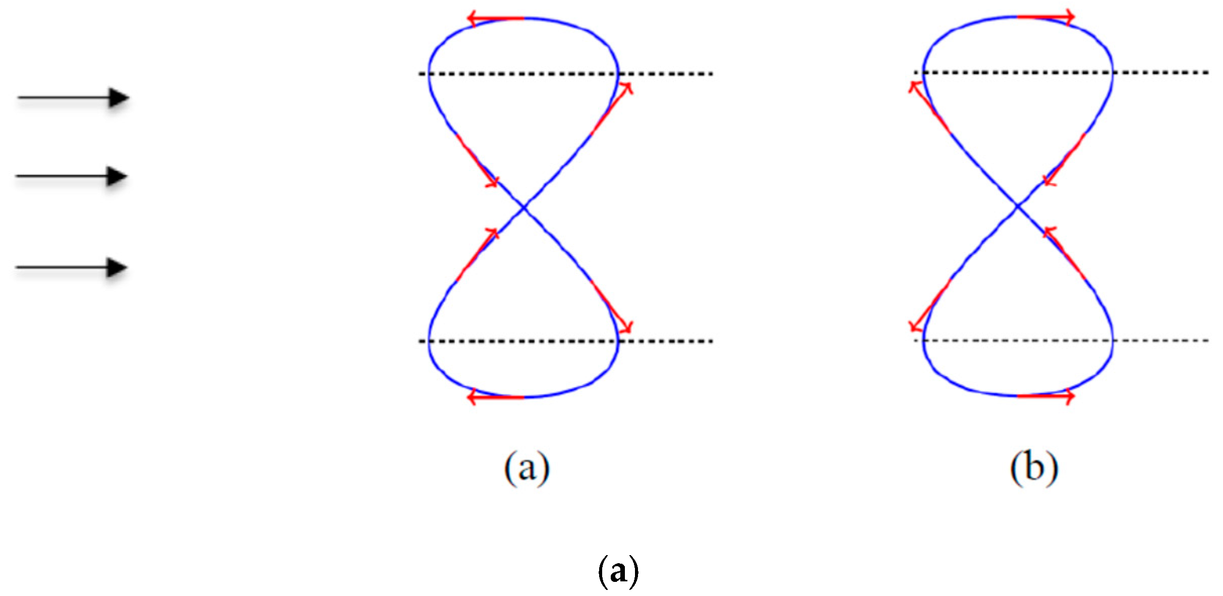
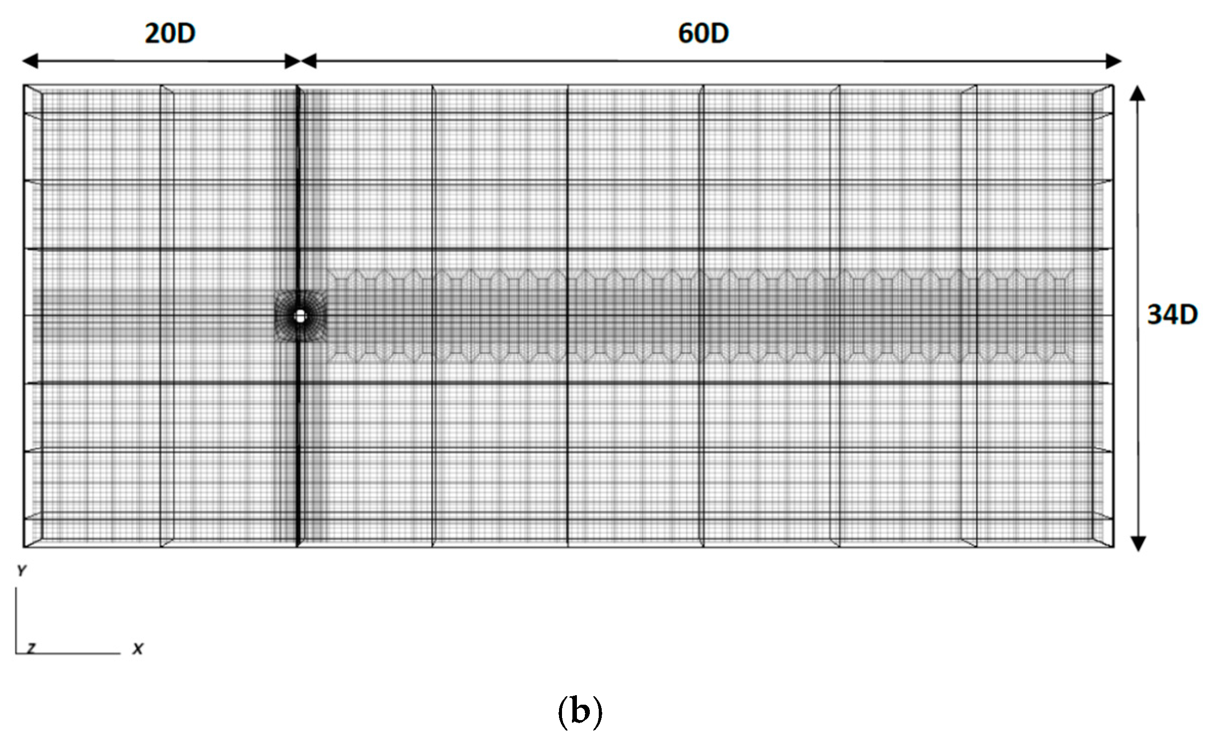
2. Formulation and Numerical Method

We consider a cylinder of diameter D that is forced to oscillate with respect to a uniform stream, following a figure-eight trajectory. The velocity of the fluid upstream the cylinder is U , and the density and kinematic viscosity of the fluid are, ρ and ν, respectively. The Reynolds number of the flow is defined as R e = U D / ν , and is equal to 400, which is the same value as in [22], and close to the one in the experiment of Williamson and Roshko [24]. We use a Cartesian system of coordinates in which the x-axis is parallel to the flow direction, the y-axis is perpendicular to the flow, and the z-axis expands along the span of the cylinder. The cylinder undergoes an oscillatory motion, characterized by oscillation amplitudes Ay and Ax in the transverse and streamwise direction, respectively, and corresponding oscillation frequencies fy and fx. The frequency of in-line direction is twice the transverse frequency (fx = 2fy). The instantaneous displacement of the cylinder in the y-direction and x-direction is defined as:
η y = A y sin ( 2 π f y t )
η x = ± A x s i n ( 2 π f x t ) = ± A x s i n ( 4 π f y t )
For a flow from left to right, the plus (+) sign in Equation (2) corresponds to a motion which is counter-clockwise in the upper x-y plane, and the minus (−) sign to a clockwise motion in the upper x-y plane. It is further noted that the in-line oscillation can be characterized by a phase shift, θ, with respect to the transverse oscillation, i.e., η x = A x s i n ( 4 π f y t + θ ) , resulting in different trajectories and direction of the cylinder motion. The figure-eight counter-clockwise and clockwise motion corresponds to values of phase shift θ = 0 and θ = π, respectively. A different physical problem is defined for each of the two motions. Considering, for example, the location with maximum distance from the x-axis, the cylinder is moving against or in the direction of the incoming stream, for counter-clockwise or clockwise motion, respectively (Figure 1a). Other values of θ, than 0 and π considered here, correspond to different orbits, and thus different flow dynamics and associated forces. The present study only considers the cases of the two figure-eight trajectories, which are encountered in VIV, and can be used as reference cases, against which others can be compared.
The lift and drag forces are acting on the cylinder, in the transverse and in-line direction, respectively. The total lift and drag force, per cylinder unit length, are scaled with the dynamic pressure, yielding the lift and drag coefficient, respectively:
F y = 1 2 ρ U 2 D C L
F x = 1 2 ρ U 2 D C D
The instantaneous lift coefficient, C L , can be decomposed into the time-averaged value, < C L > , and the instantaneous fluctuations, C L , i.e., C L = C L + C L , where C L = 1 / T 0 T C L d t , with T representing a large integration time, consisting of an integer number of oscillation periods. Correspondingly, the drag coefficient,   C D , is decomposed as: C D = C D + C D where C D = 1 / T 0 T C D d t .
From dimensional analysis, it follows that the non-dimensional force coefficients are functions of: the Reynolds number, the normalized y-amplitude (Ay/D), the amplitude ratio, ε = A x / A y , and the frequency ratio F = f y / f s , where fs is the non-dimensional vortex shedding frequency in flow past a stationary cylinder (Strouhal frequency). For Re = 400, fs = 0.204 [22].
An important quantity for VIV is the net power transfer from the fluid to the structure, with positive values corresponding to excitation, and negative values corresponding to damping. Since a rigid oscillating cylinder is considered in the present study, the instantaneous displacement is uniform along the cylinder span. The instantaneous power transfer per cylinder unit length is readily obtained from the product of instantaneous force components (per cylinder unit length) and the instantaneous cylinder velocity components. The time-average power (per cylinder unit length) transferred from the flow to the cylinder can be normalized by 1 2 ρ U 3 D , yielding the non-dimensional “power transfer parameter”. In the present case of both transverse and in-line cylinder oscillation, the total value of time-average power transfer parameter consists of the sum of the corresponding contributions of the y- and x-motion:
P = 2 ρ U 3 D 1 T { o T F y d η y d t d t + 0 T F x d η x d t d t }
The equations governing the fluid motion are the continuity and Navier–Stokes equations. We nondimensionalize all lenghts by D, all velocities by U , time by D / U , and pressure by ρ U 2 , and write the incompressibility and Navier–Stokes equations as:
u = 0
u t + u u = p + 1 R e 2 u
where u is the vector of the absolute fluid velocity, and R e is the Reynolds number of the flow.
On the cylinder surface, the fluid’s instantaneous velocity is equal to the cylinder velocity, i.e., u = d η x d t i + d η y d t j + 0 k , where (ηx, ηy, 0) is now the non-dimensional cylinder displacement, and i , j , k are the unit vectors in the three directions. To avoid reconstructing the computational grid at each time step, we use a frame of reference fixed on the cylinder. Let u now express the relative velocity with respect to the moving cylinder. The incompressibility equation remains unchanged, while the momentum equation (Equation (7)) becomes:
u t + u u = p + 1 R e 2 u d 2 η x d t 2 i d 2 η y d t 2 j
i.e., a d’Alembert acceleration appears on the right-hand side of Equation (8). This means that, in order to find the actual force components acting on the cylinder, we need to subtract from the computed force a “dynamic Archimedes” force, equal, per cylinder unit length, to ( π / 4 ) ρ D 2 d 2 η y / d t 2 j and ( π / 4 ) ρ D 2 d 2 η x / d t 2 i , for its lift and drag component, respectively.
For the above problem formulation, the flow boundary conditions referring to the x-y cross-sections are implemented as follows: (i) at the inflow and side boundaries, u y = d η y d t j   , u x = 1 i d η x d t   i , u z = 0 k , (ii) on the cylinder surface, u = 0 , (iii) at the outflow, maintain Neumann-type boundary conditions, u η = 0 . Finally, periodic boundary conditions are specified for the end planes in the spanwise direction.
The parallel code Nek5000 [25], based on the spectral element method [26,27] is used to solve Equations (6) and (8) constrained by the above boundary conditions. The spectral element method (SEM), used for spatial descritization, employs high-order weighted residuals for the solution of partial differential equations, based on orthogonal polynomials and highly accurate numerical quadrature. In SEM, each element involves a separate discretization mesh with the same number of collocation points in each direction, and the dependent variables are expanded in terms of Legendre polynomials. In each spatial direction, the number of collocation points in each element is equal to the order of the polynomials plus one.
The computational domain extends 60D downstream and 20D upstream from the centre of the cylinder. In the vertical direction, the domain extends symmetrically from the cylinder centerline to a maximum distance of 17D. The extent of the domain in the spanwise direction (z-direction) is equal to 2πD. Based on experimental results for the spanwise wavelentgh of streamwise vortices [28], as well as relevant computational studies [29], the present spanwise domain length is deemed sufficient.
In the x-y plane, 2056 spectral elements are used for domain decomposition. In the z-direction, 10 element layers are used. Thus, 20,560 three-dimensional spectral elements are used in total, and the resolution of each element is 8 × 8 × 8. The spectral element grid is shown in Figure 1b. For time discretization, a third order semi-implicit temporal scheme has been adopted [30]; the time step is Δt = 0.001. The accuracy of the resolution used in present study has been verified by thorough validation and resolution tests, also including comparisons against experiments, as reported in [22].

3. Results

We conducted Direct Numerical Simulation (DNS) of three-dimensional flow past a cylinder, for Re = 400. The present study considers both the counter-clockwise and the clockwise oscillation mode, at frequency ratios in the range F = 0.8 to F = 1.1, for a constant value of ε = 0.2, and makes proper reference to results of transverse-only oscillation (ε = 0). For all values of F, transverse oscillation amplitudes of up to 0.6 cylinder diameters are considered. For each case, the governing equations are integrated in time until a “statistical steady state” is reached, characterized by time-independent mean flow quantities. Subsequently, the equations are further integrated for several oscillation periods, and flow statistics, as time-average force coefficients and power transfer parameter, are calculated. For all cases, simulations are initialized from a lower amplitude simulation of the same oscillation frequency.

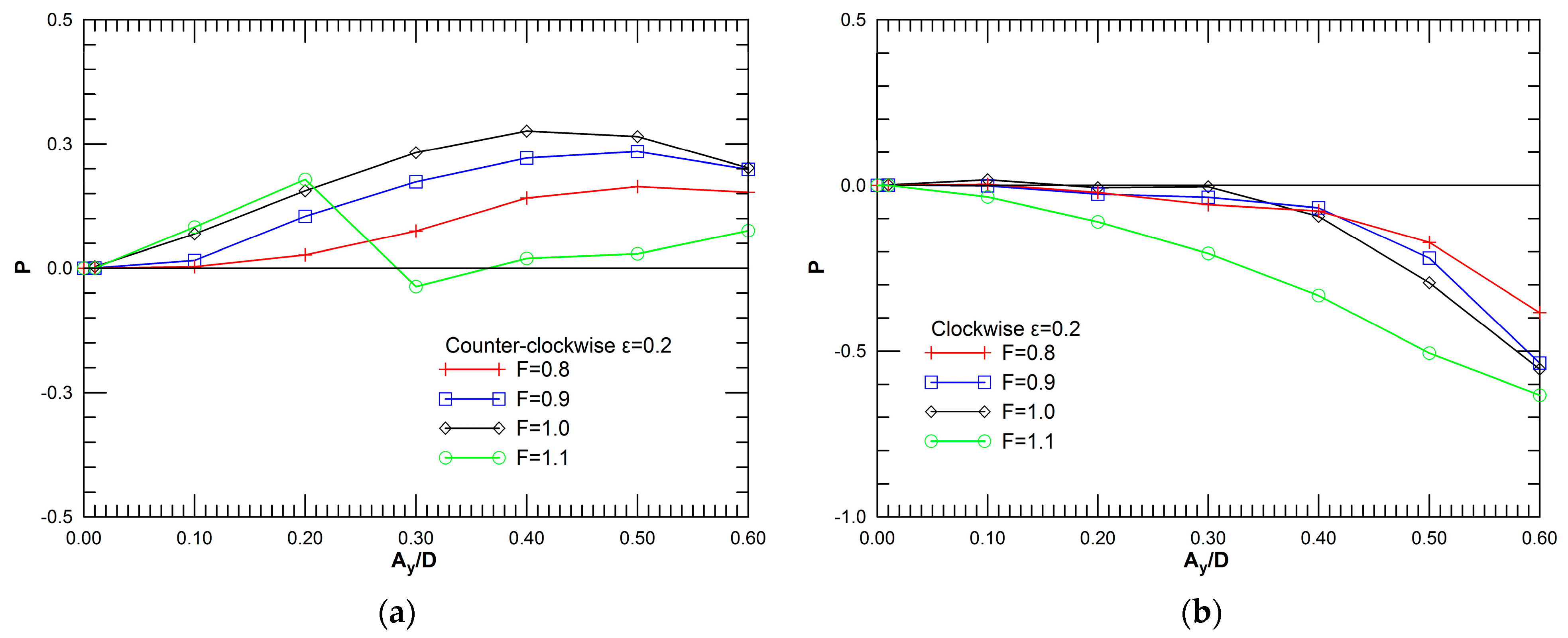
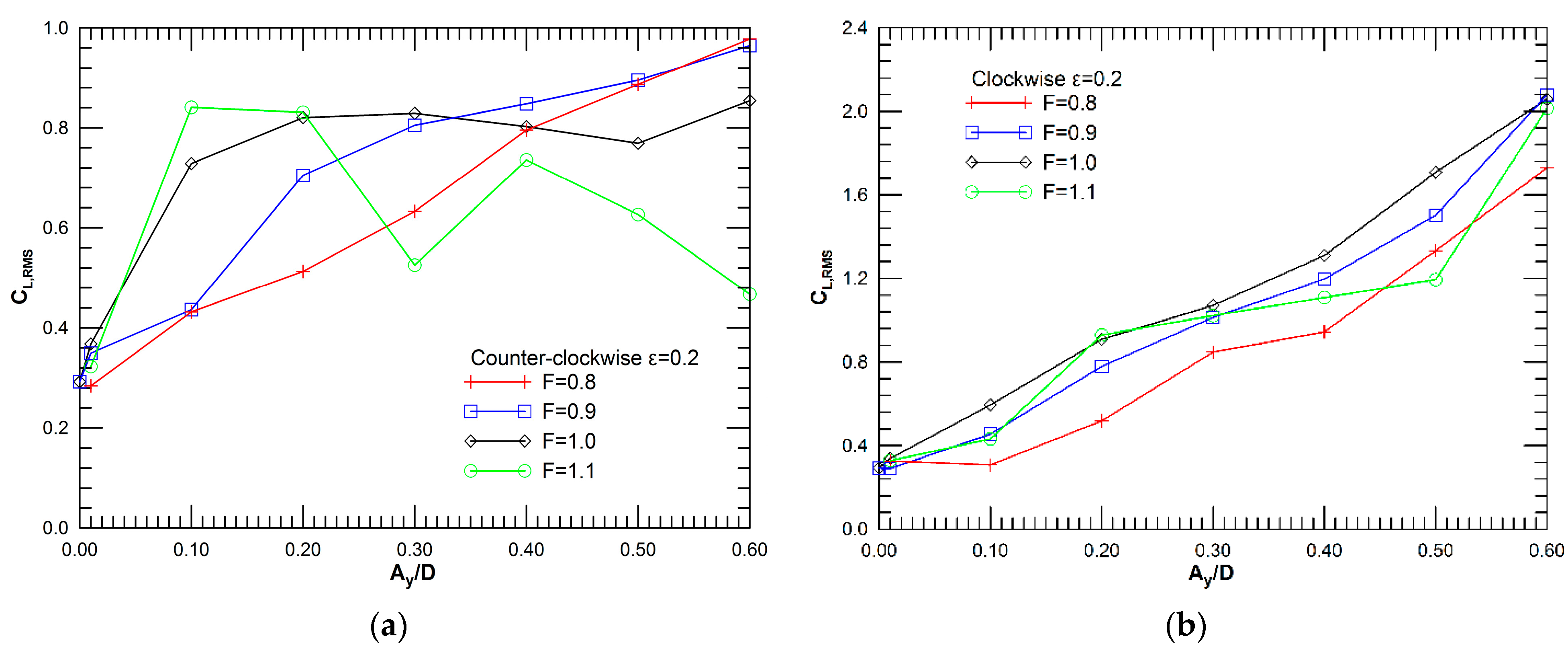
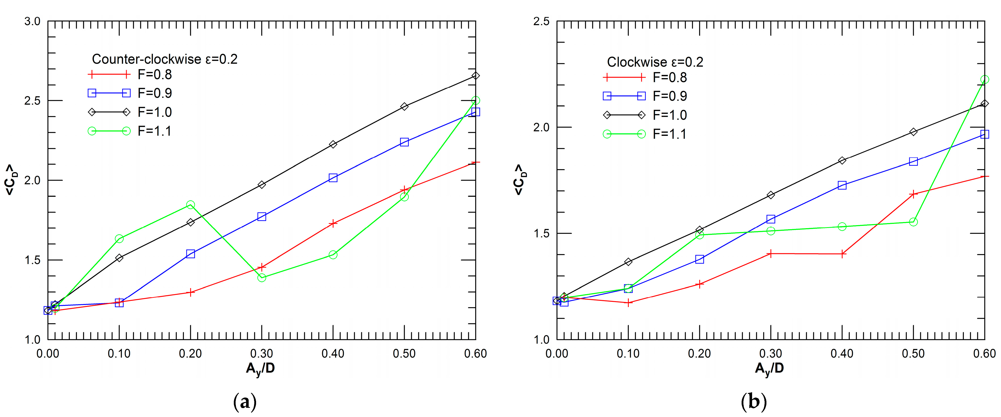
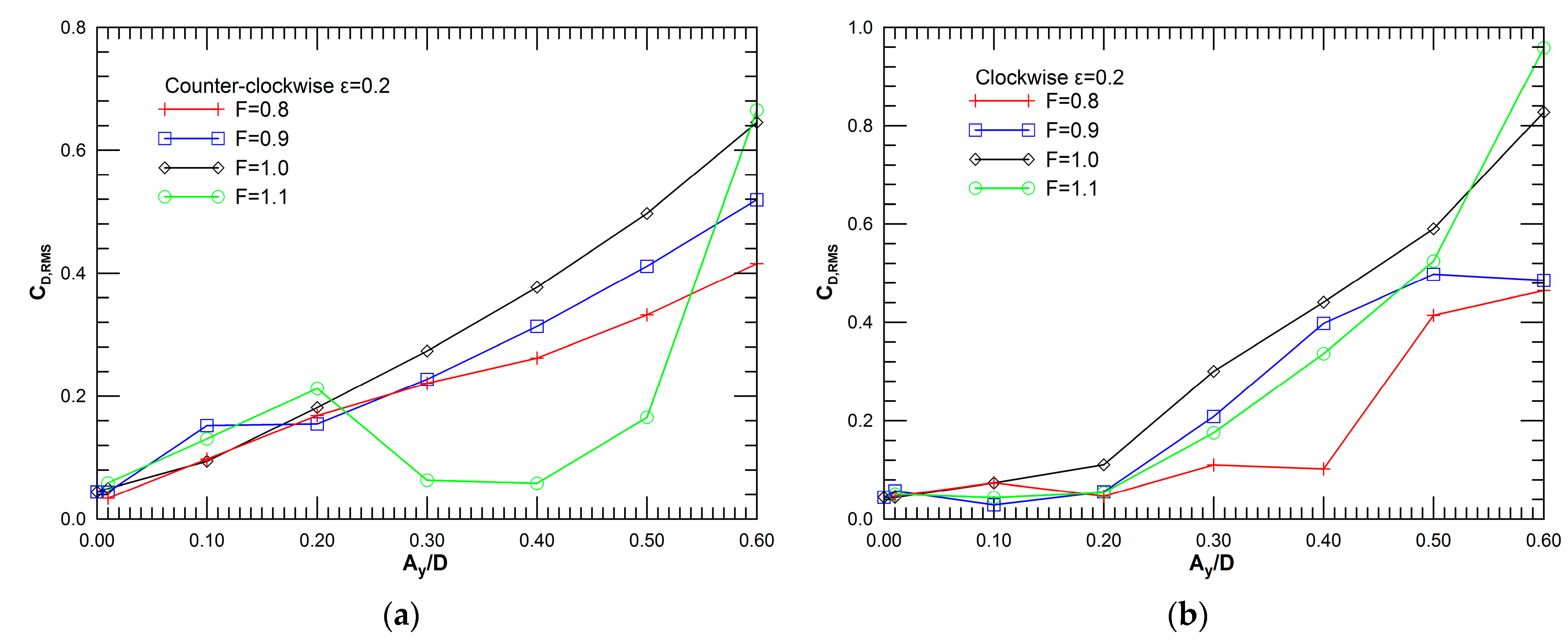
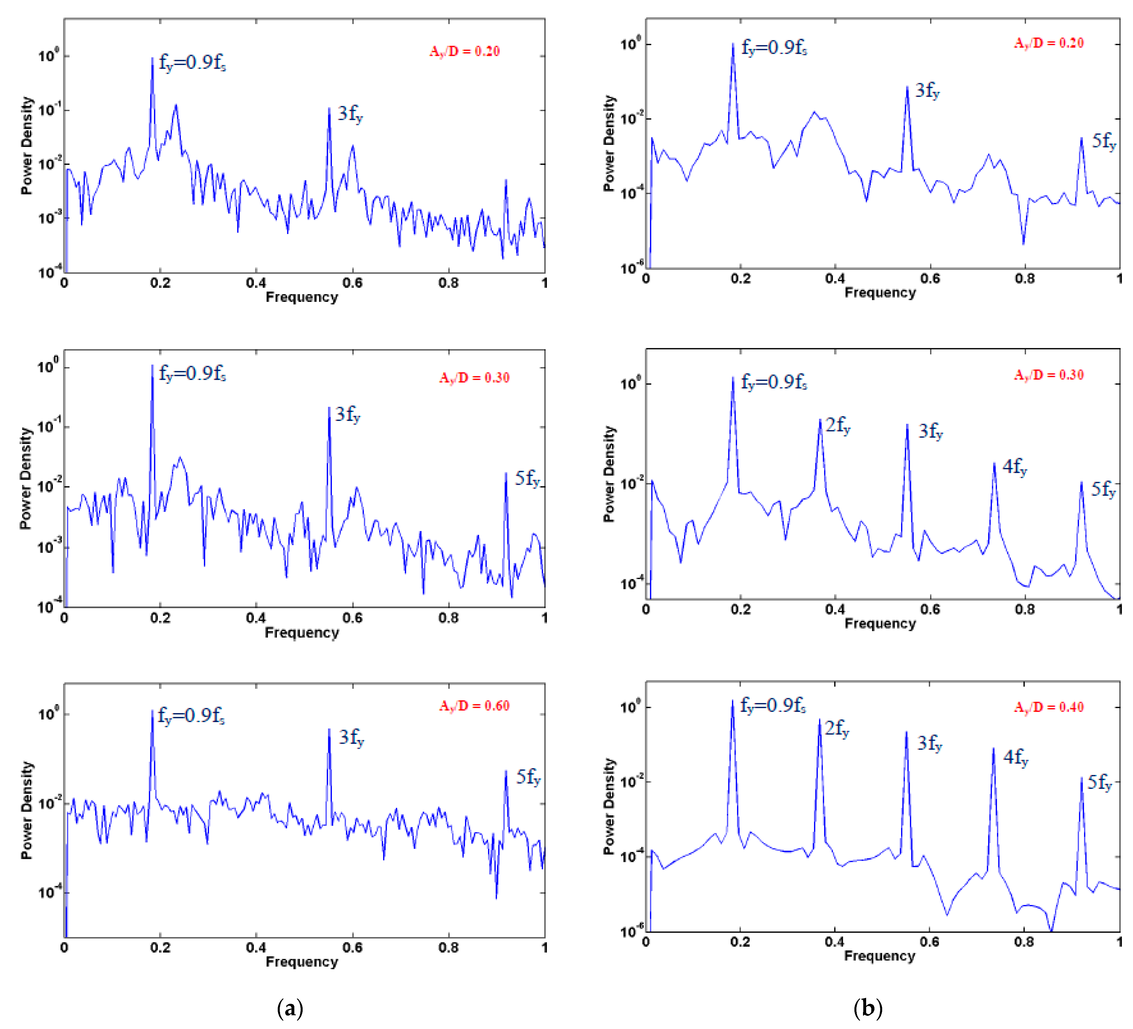
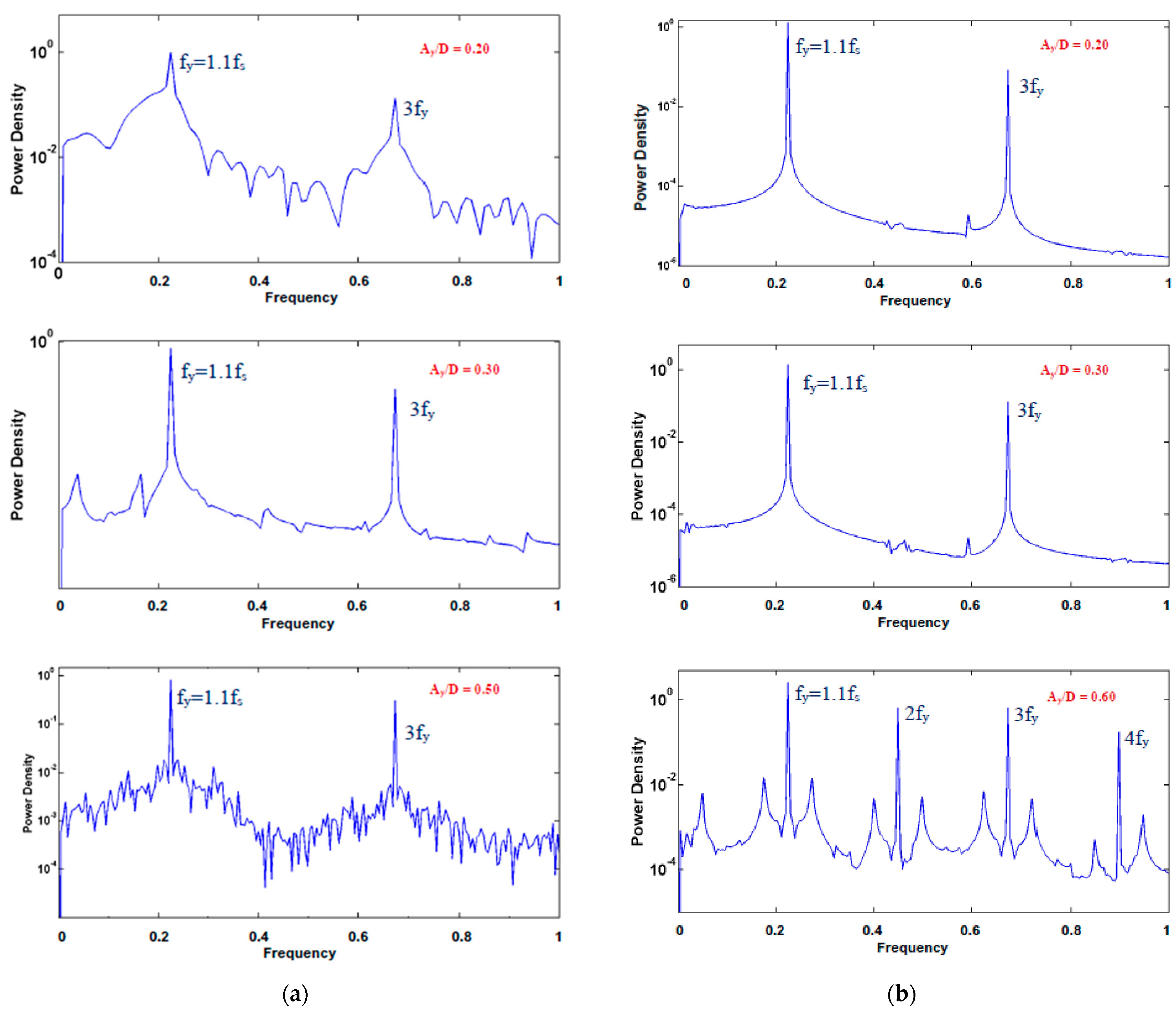
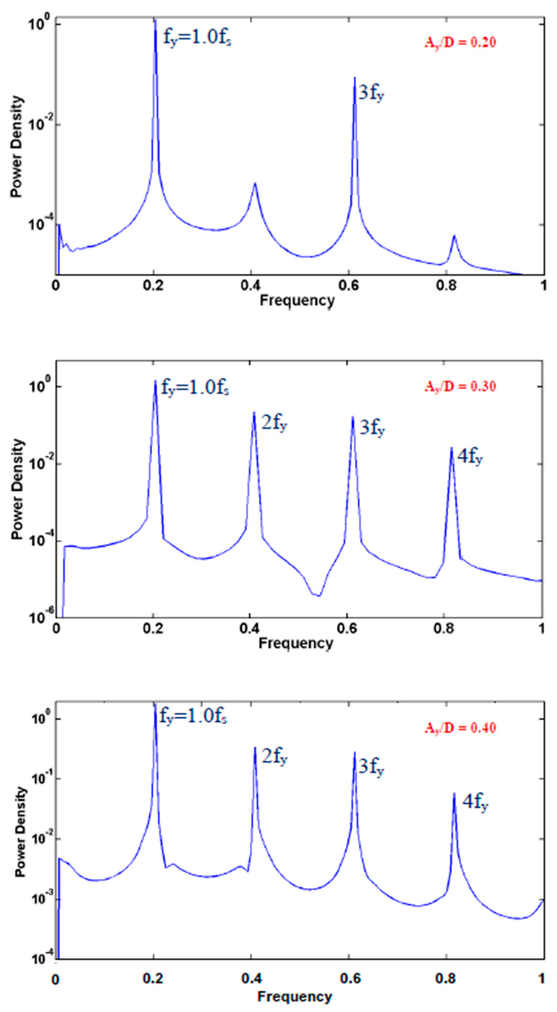
3.1. Power Transfer and Hydrodynamic Forces

In this section, results of power transfer parameter and force coefficients versus the problem independent parameters, F and Ay/D, are presented. Although power transfer is essentially uniform along the cylinder span in the present problem of flow past a rigid cylinder, variation along the span (corresponding to different oscillation patterns) has been reported for the case of flow past a long flexible cylinder in shear flow [31].
We start by presenting results for the reference problem of transverse-only oscillation (ε = 0). Figure 2a presents the variation of time-average power transfer parameter, P, with oscillation amplitude, for the frequency values of the present study. These results indicate that, for F ≤ 1, P initially increases with Ay/D, reaches a maximum, and decreases for non-dimensional oscillation amplitude higher than about 0.4; negative values of P are obtained for Ay/D values higher than about 0.5, in agreement with the results of Leontini et al. [9] and Peppa et al. [32] for two-dimensional flow at lower Reynolds numbers. For the case of above-resonant forcing (F = 1.1), among the amplitudes considered, a positive value of P is only obtained for Ay/D = 0.5, accompanied by a drastic increase in time-average drag coefficient, <CD> (Figure 2b). The drag coefficient is monotonically increasing for resonant forcing (F = 1). For F < 1, increasing <CD> values are obtained after a threshold value of oscillation amplitude, and this should be associated with lock-in of the vortex street to the forcing frequency.
Figure 3a presents the variation of time-average power transfer parameter, P, with oscillation amplitude, for the counter-clockwise mode, for the different frequencies considered, while Figure 3b presents the corresponding variation for the clockwise mode. A comparison with the results of transverse-only oscillation (Figure 2a) shows that the values of P attained for counter-clockwise oscillation are higher, with positive values still maintained for Ay/D = 0.6. Consequently, VIV in terms of a counter-clockwise should only occur at higher oscillation amplitude. For the clockwise mode, for F ≤ 1, P is nearly zero at low oscillation amplitude, and is negative and decreasing for Ay/D values higher than about 0.3; negative values, characterized by a monotonic decrease with Ay/D, are attained for F = 1.1. Thus, the appearance of a clockwise mode is less likely in VIV.
An important feature of flow past a cylinder is the forces exerted on the body, expressed in terms of the lift and drag coefficient. The variation of fluctuation intensities of lift coefficient, CL,RMS, with oscillation amplitude, for the different values of transverse oscillation frequency, is presented in Figure 4a,b, for the counter-clockwise and the clockwise mode, respectively. Interestingly, for the counter-clockwise oscillation at F = 1.0, the lift fluctuation curve remains flat for Ay/D ≥ 0.2. For F = 1.1, a significant variation is found around Ay/D = 0.30, which is in correspondence with the sharp decrease in the value of power transfer parameter (Figure 3a). For clockwise motion, a monotonic increase of CL,RMS with oscillation amplitude is found (Figure 3b), with the values attained in the high end of oscillation amplitude being higher than those for counter-clockwise motion by a factor of two.
The variation of time-average and RMS fluctuation of drag coefficient is presented in Figure 5 and Figure 6, respectively. In general, a monotonic increase of drag with oscillation amplitude is found, for both oscillation modes. A less ordered variation is observed for F = 1.1, especially for the counter-clockwise mode. Interestingly, in the high end of amplitudes considered, lower levels of drag coefficient are computed for the clockwise mode, suggesting a narrower wake, in comparison to the counter-clockwise mode.
The flow structure and dynamics affects the frequency content of forces. Computed lift coefficient spectra are presented for the two oscillation modes in Figure 7a,b (F = 0.9), Figure 8a,b (F = 1.1) and Figure 9 (F = 1.0, clockwise mode), for representative values of transverse oscillation amplitude, Ay/D ≥ 0.2. In all cases, the spectra demonstrate the absence of Strouhal frequency, and the presence of the excitation frequency and its higher harmonics (lock-in). For F = 0.9, the spectra of both modes exhibit a strong peak at the third harmonic (Figure 7a,b), while they also show the next higher odd harmonic; even harmonics exhibit a strong presence in the case of the clockwise mode (Figure 7b), and are absent from the counter-clockwise mode spectra (Figure 7a). The results presented for F = 1.0 verify the presence of both odd and even harmonics (Figure 9), similarly to the results obtained for F = 0.9. For F = 1.1, the lift spectra of the counter-clockwise mode show the strong presence of the third harmonic, as well as the absence of even harmonics (Figure 8a); for clockwise oscillation, the spectra are populated by only odd harmonics at low and moderate oscillation amplitude, and by both odd and even harmonics at high amplitude (Figure 8b).
Thus, for all cases, a strong presence of odd harmonics of the first lift component (corresponding to the transverse oscillation frequency) is found. This is in accordance with the results of Peppa et al. [22] for flow past a cylinder forced at the Strouhal frequency, oscillating in the transverse-only direction or following a counter-clockwise figure-eight trajectory. In particular, the presence of the third harmonic is verified here as an important flow characteristic of flow past an oscillating cylinder, in agreement with the findings of previous investigations, as the VIV study of Dahl et al. [18]; the third harmonic is found to become more pronounced at increasing oscillation amplitude. Moreover, for all frequencies considered for the case of the clockwise mode, even harmonics are present in the lift spectrum at sufficiently high values of transverse oscillation amplitude.

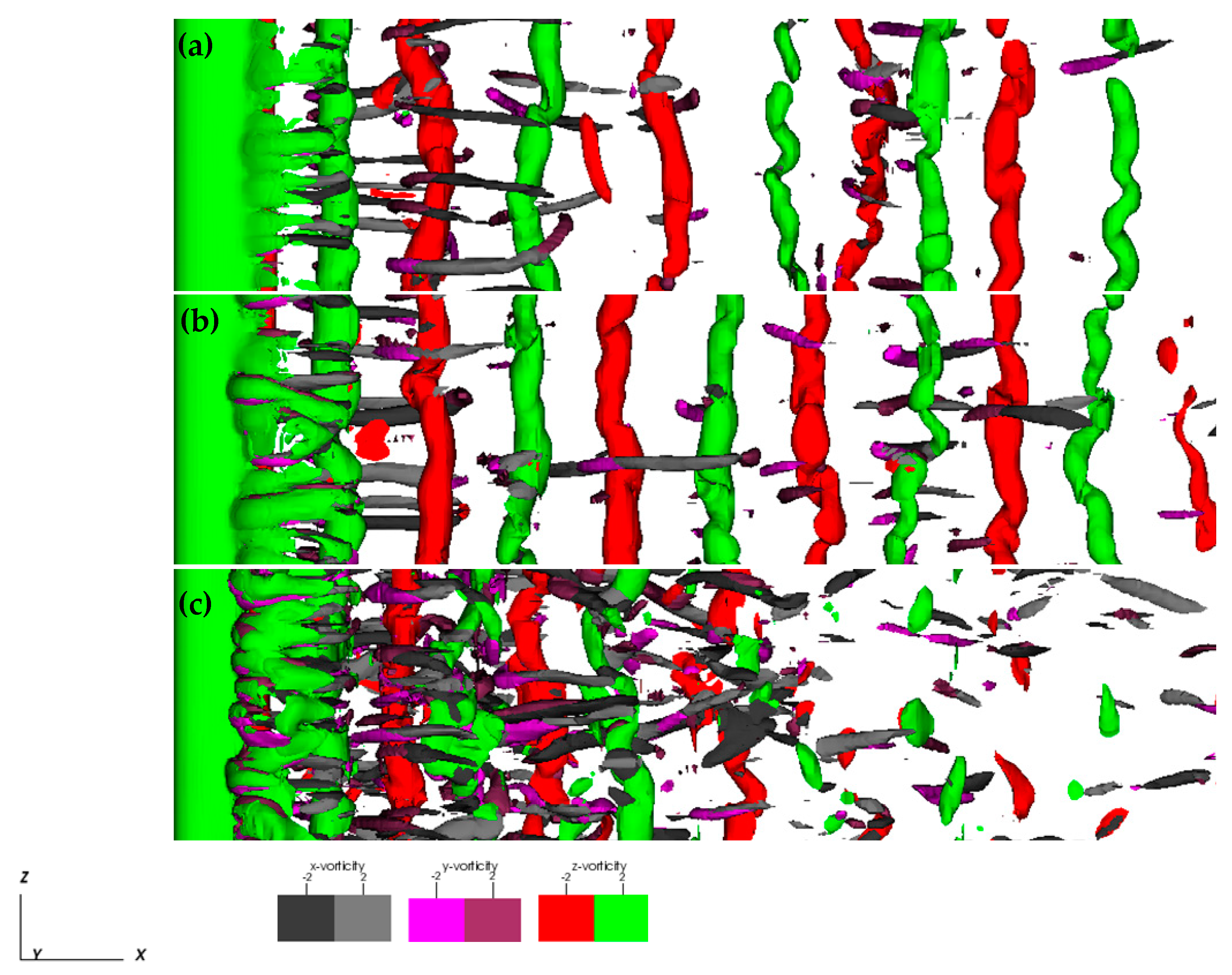
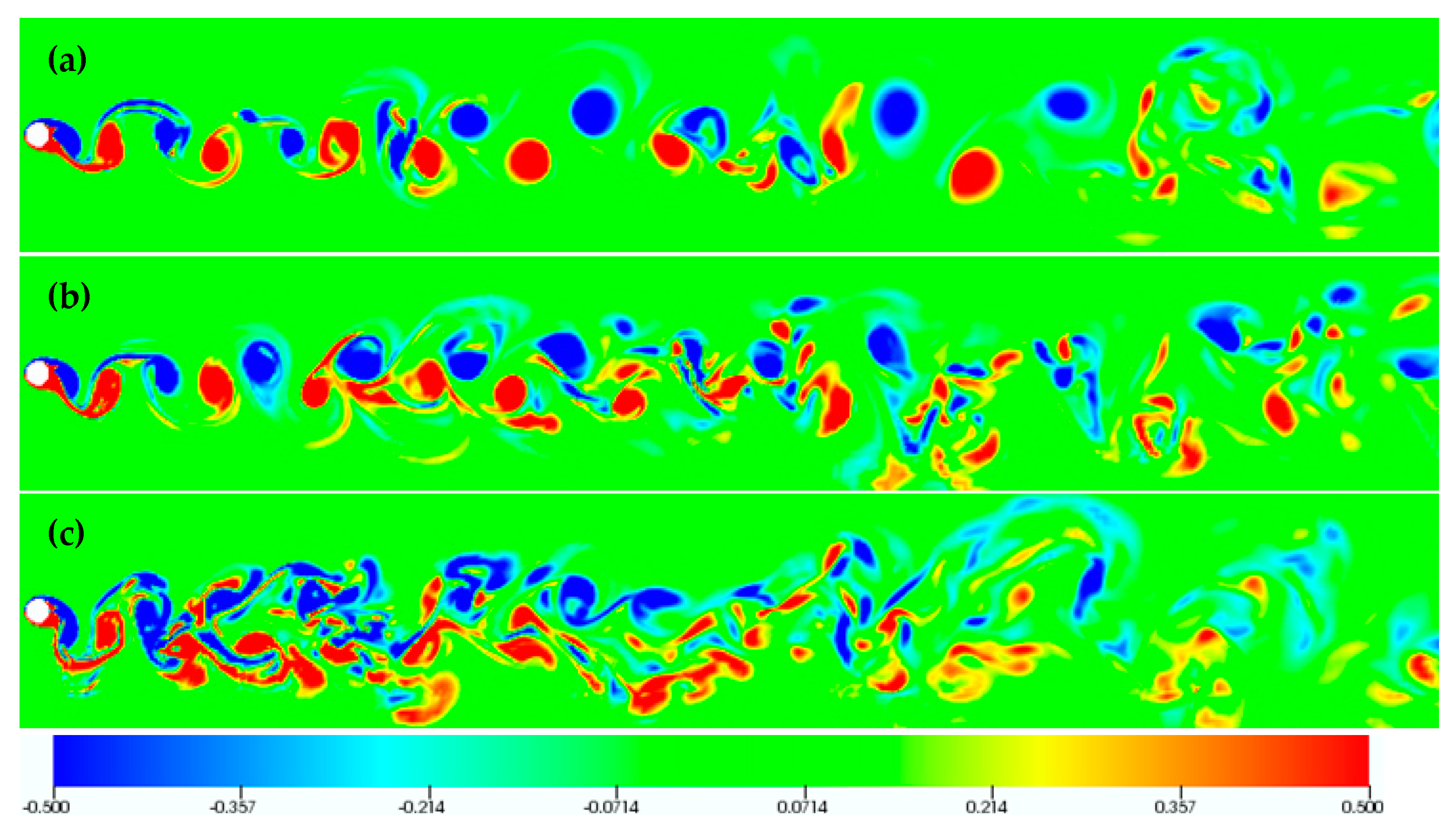
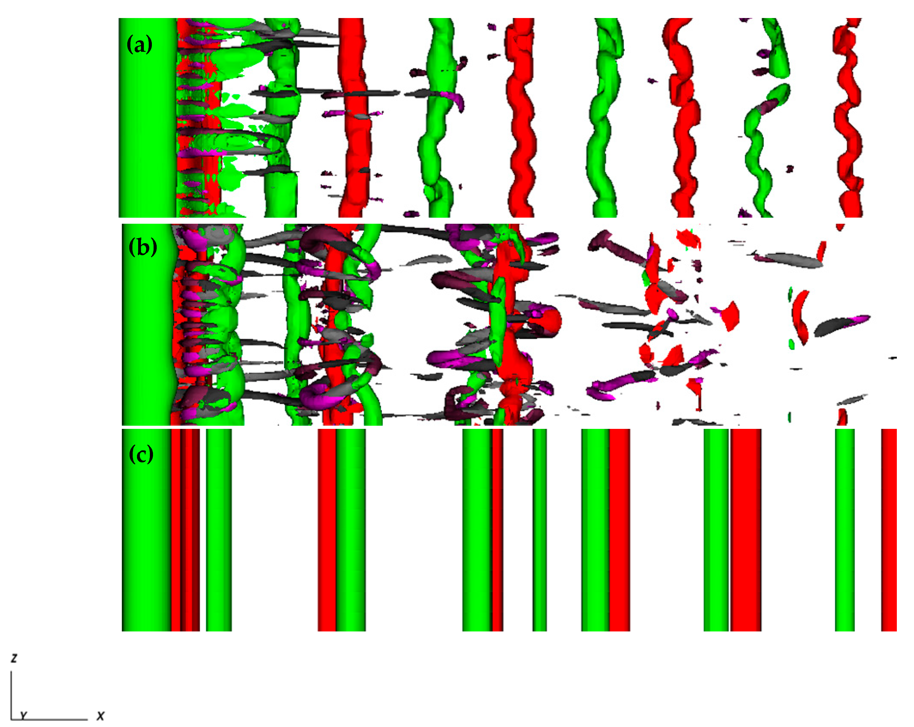
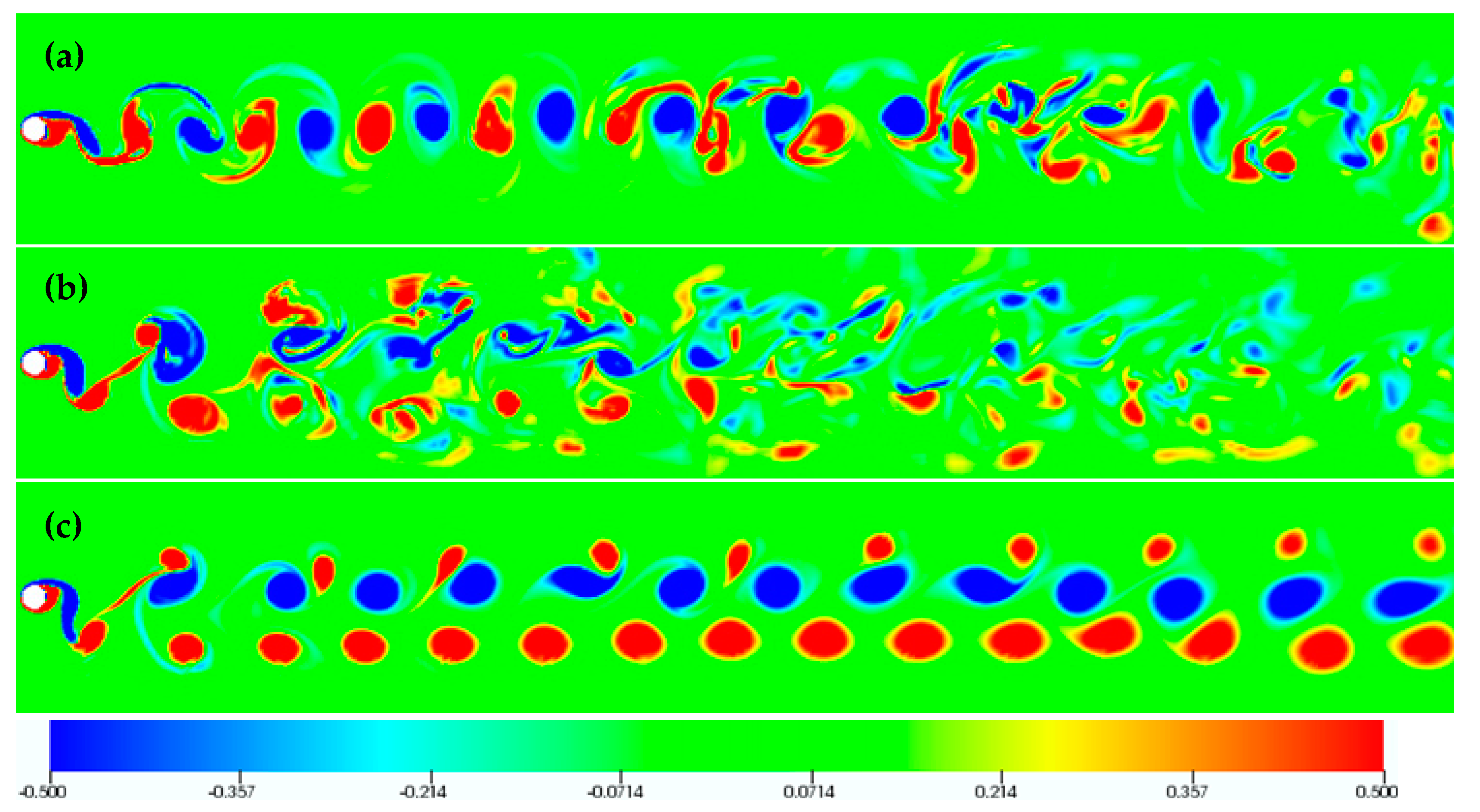
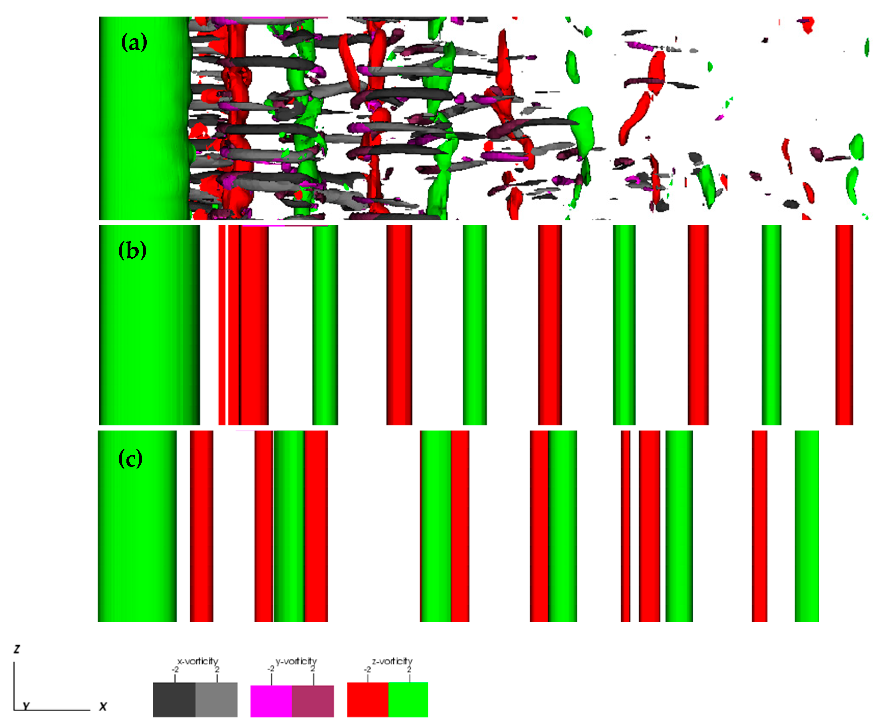
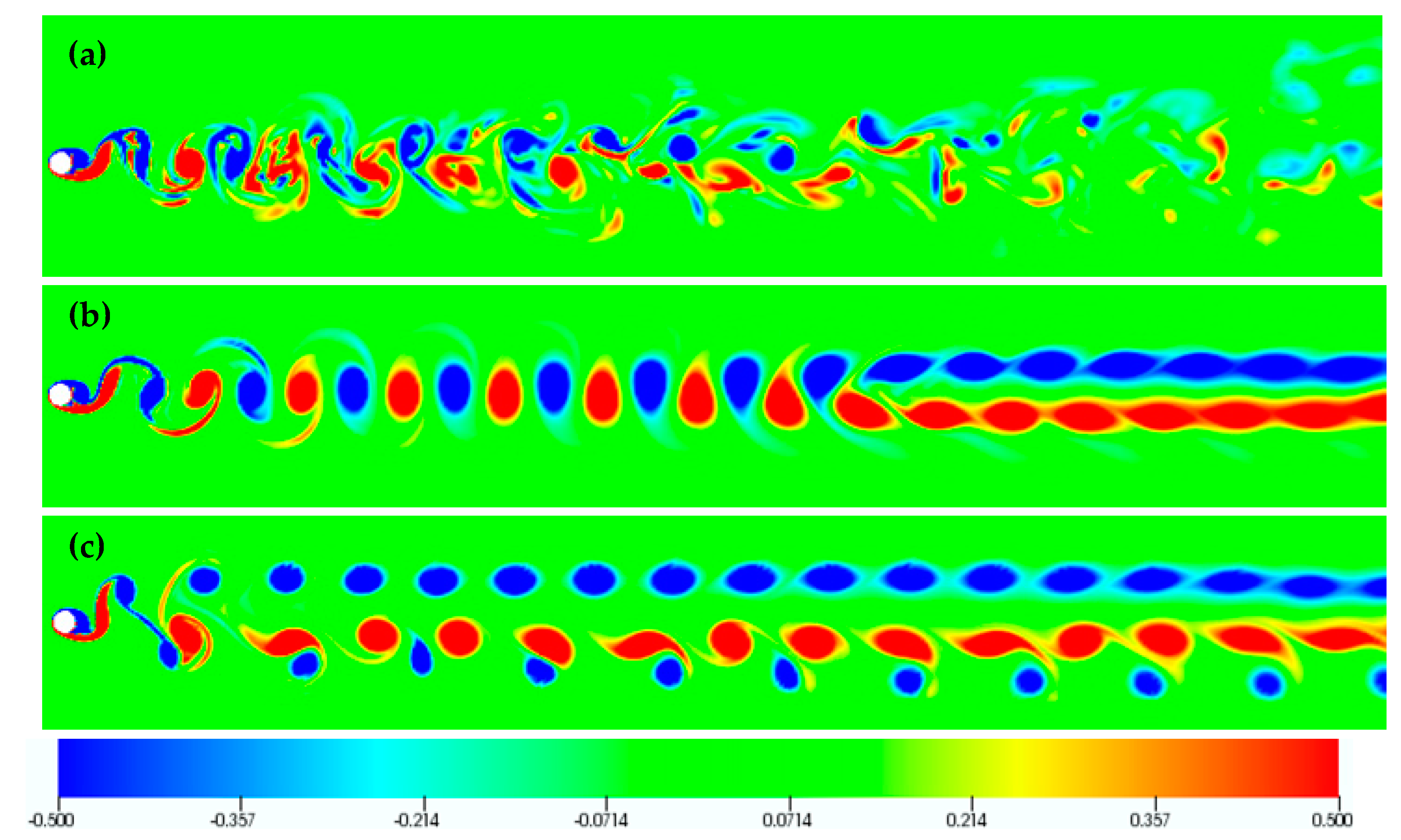
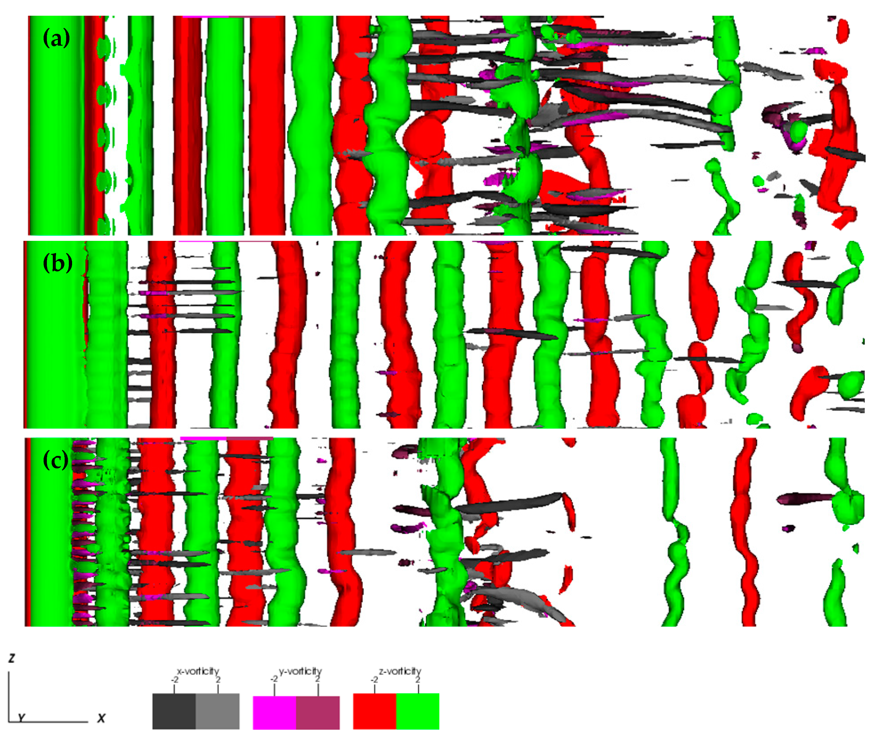
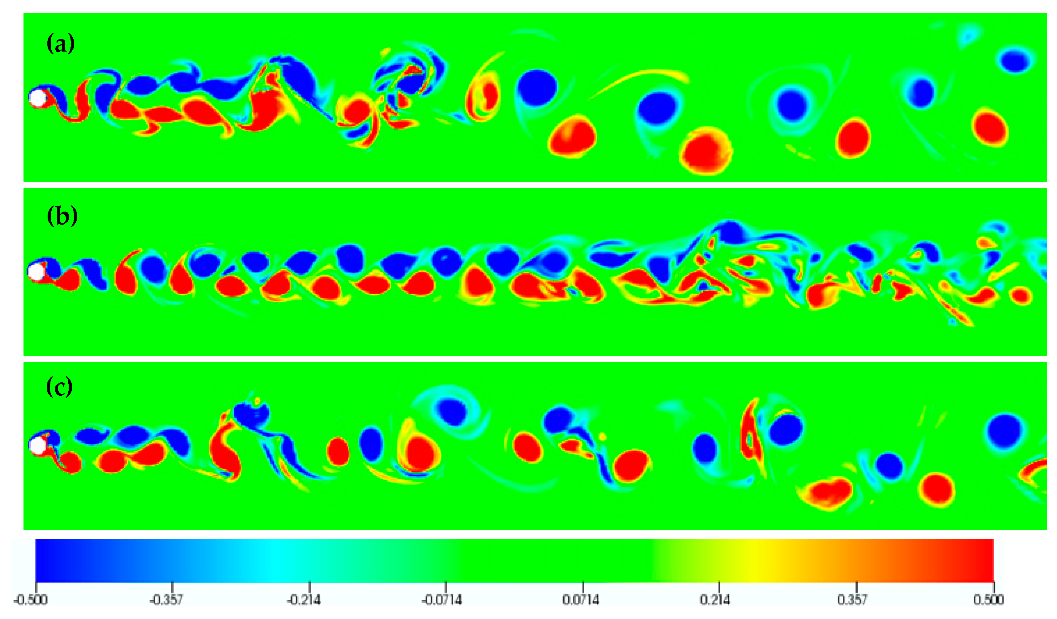
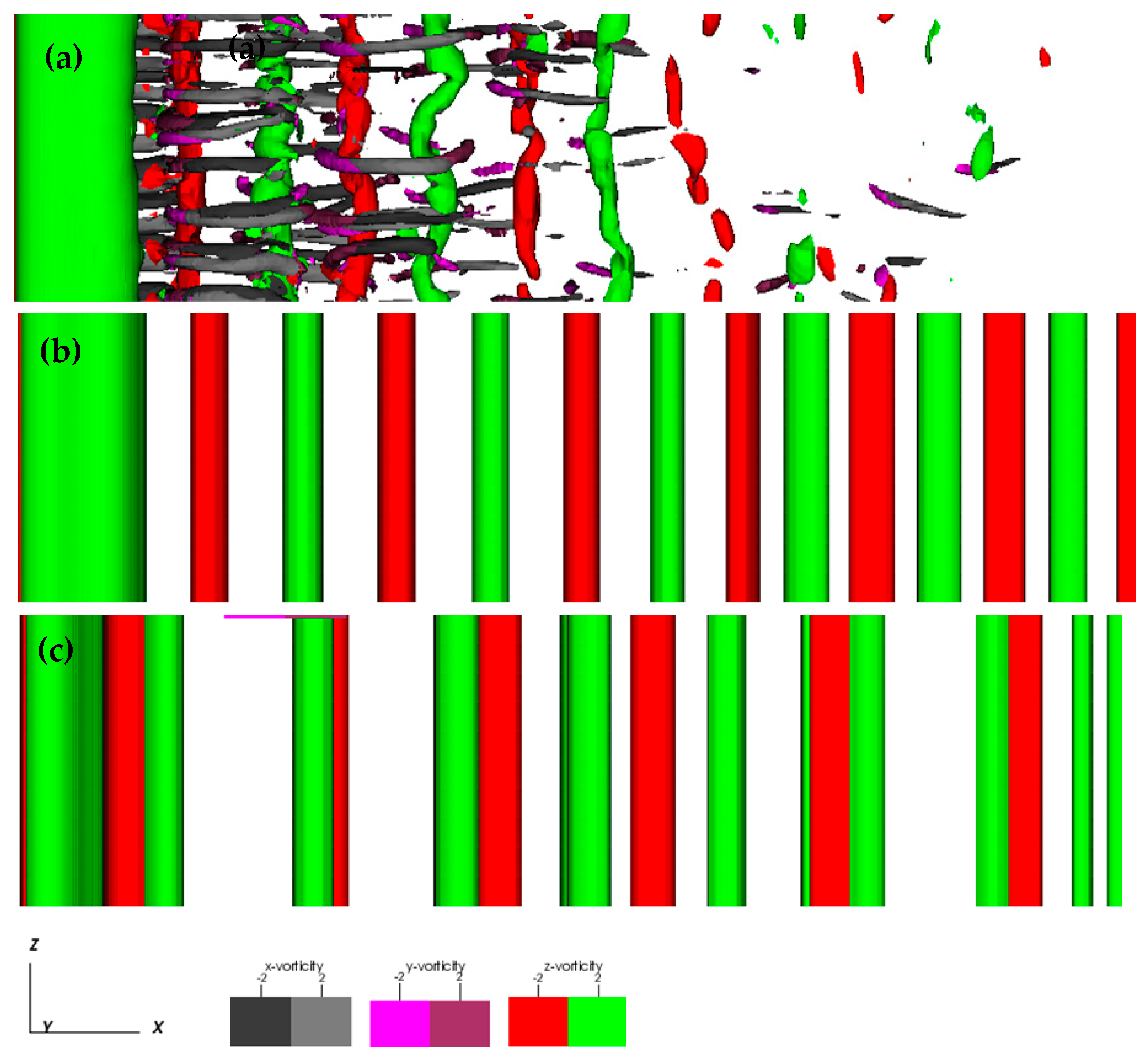
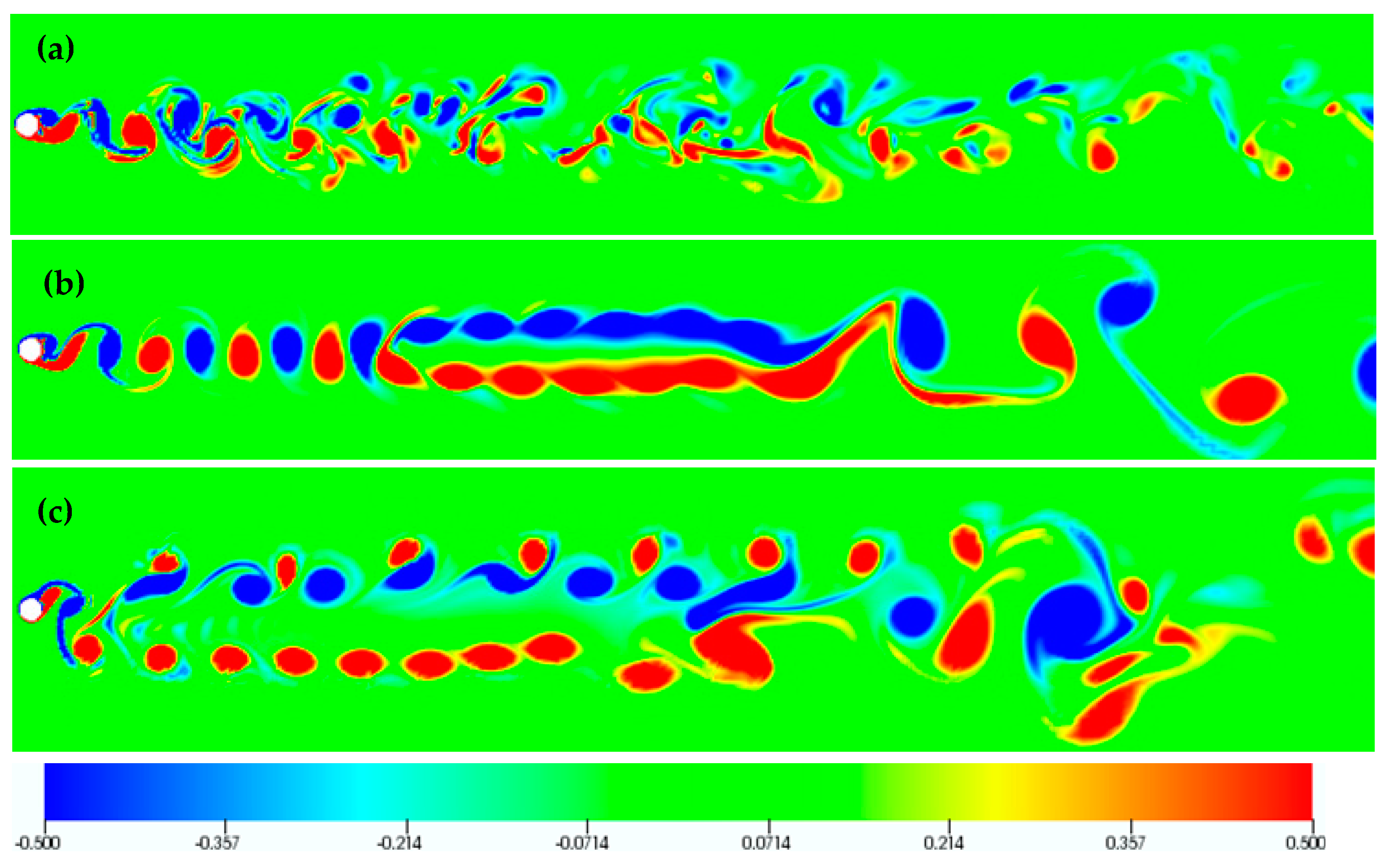
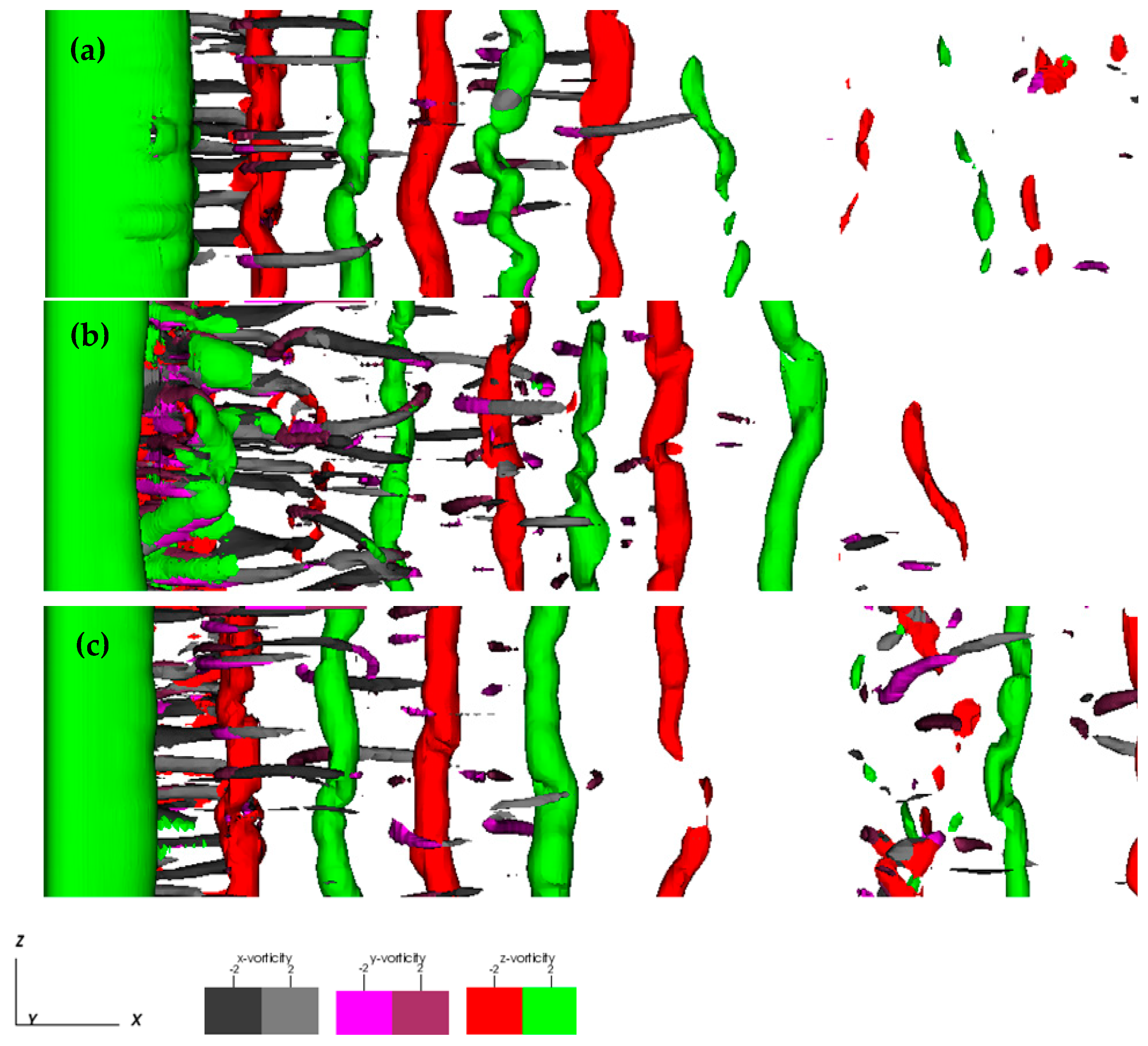
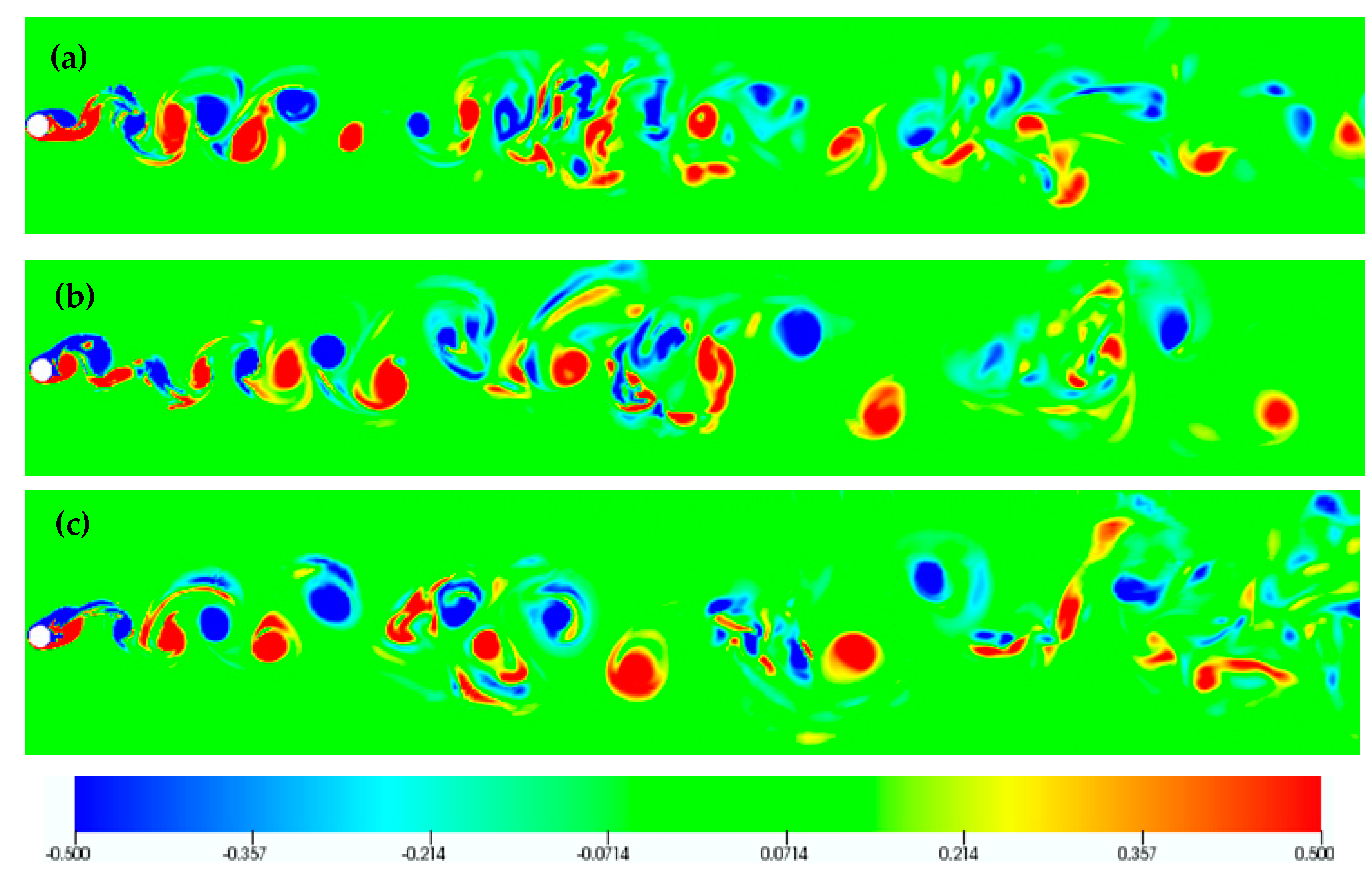
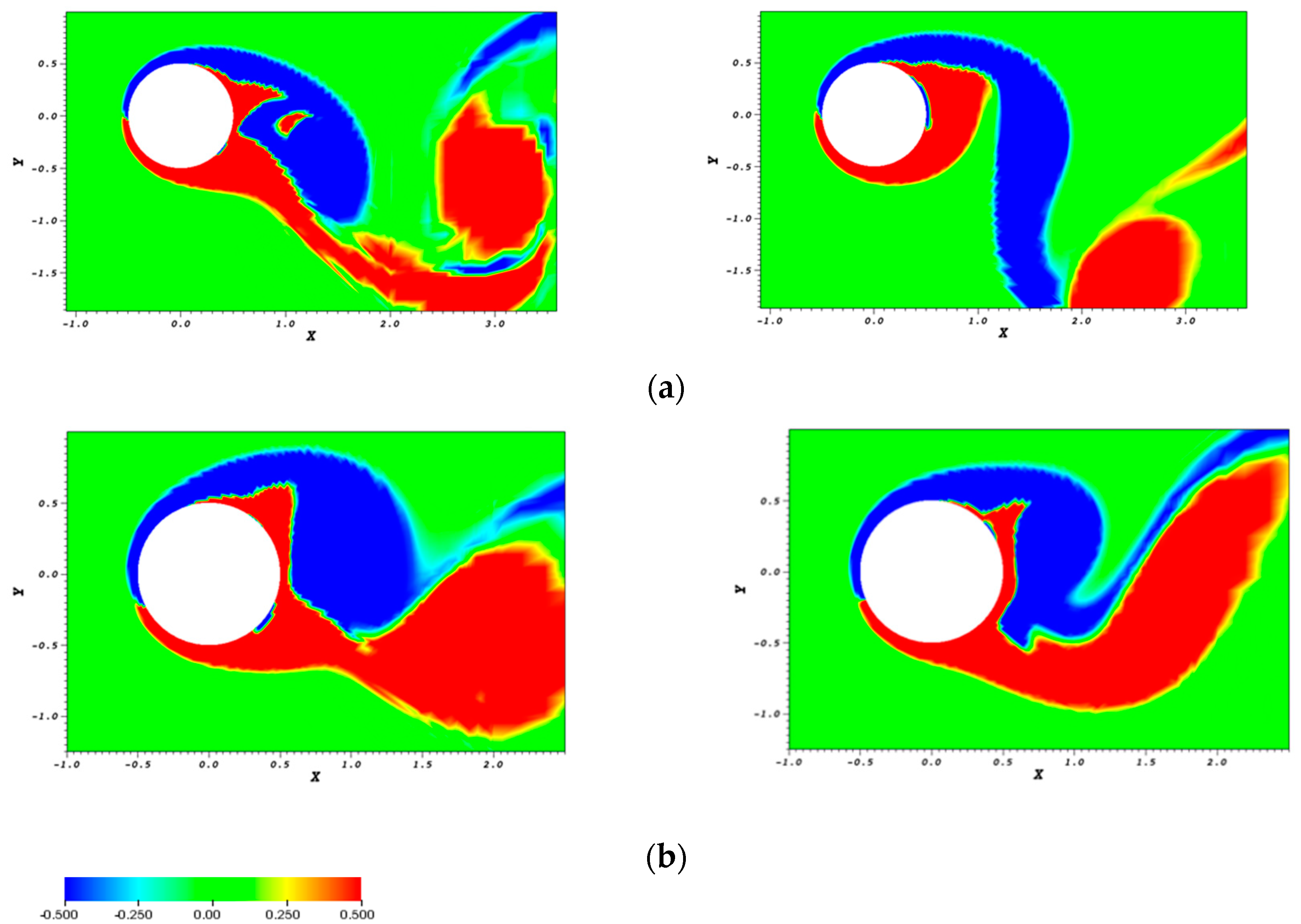
3.2. Visualization of the Flow in the Wake

In this section, we present flow visualizations in terms of vorticity isocontours, in order to characterize the flow structure and relate it to the results of power transfer and force coeffecients, already presented. Flow past a stationary cylinder at Re = 400 has the structure of Mode B [28], characterized by the presence of spanwise rolls (2S shedding), and counter-rotating streamwise vortex pairs. Cylinder oscillation is thus expected to affect this wake structure. Visualizations of computed flow fields are presented here in terms of isosurfaces of ω = ±2, for all three vorticity components. All visualizations refer to the mean position of the oscillating cylinder, i.e., ηy/D = ηx/D = 0. For resontant forcing, Peppa et al. [22] have shown that, for the counter-clockwise mode, the flow three-dimensionality is reduced at low oscillation amplitude, with the flow becoming increasingly more complex at higher amplitudes, while always maintaining the 2S shedding mode.
First, results are presented for counter-clockwise cylinder oscillation at F = 0.9, in terms of the vorticity isosurfaces shown in Figure 10. A moderate three-dimensionality is present at the lower oscillation amplitudes of 0.20 and 0.30; the wake is strongly three-dimensional at the high oscillation amplitude of 0.60. The 2S shedding mode is present at all oscillation amplitudes, as also illustrated by the spanwise vorticity isocontours in a plane of constant z in Figure 11. For the same oscillation frequency (F = 0.9), flow visualization for clockwise cylinder oscillation is presented in Figure 12 and Figure 13, for three values of transverse oscillation amplitude (0.20, 0.30, 0.40). The results show a 2S mode at the low oscillation amplitude, and the presence of a more complex structure associated with vortex splitting at higher amplitudes (Ay/D = 0.30–0.40), commonly referred to as the “S+P” wake mode. Interestingly, a full return to two-dimensional flow is attained at the transverse oscillation amplitude of 0.40. The shedding mode characterized by the presence of vortex splitting has first been reported in [33], and characterized as “partial S+P” mode. These flow visualizations demonstrate that the “S+P” mode is the cause of the even harmonic frequency components identified in the lift spectrum (Figure 7b).
Figure 14 and Figure 15 present flow visualizations at resonant forcing (F = 1.0) for the clockwise mode. This case has been first discussed in the Conference papers of Peppa et al. [34,35], and the results are included here for completeness. Figure 14 presents the flow structure for three values of transverse oscillation amplitude (0.10, 0.20, 0.30); a clear convergence to a two-dimensional 2S wake is demonstrated already at Ay/D = 0.20. For the same cases, Figure 15 presents a visualization of the wake in a plane of constant z. The presence of a two-dimensional wake is evident for Ay/D ≥ 0.20, as well as the presence of the “S+P” mode for Ay/D = 0.30. We note that these transitions do not have a marked effect on the variation of power transfer and force coefficients (Figure 3, Figure 4, Figure 5 and Figure 6). This should be associated with the fact that in all cases shedding is initiated as a 2S pattern, which may by modified into a “S+P” mode farther downstream. Finally, the “S+P” mode is also verified as the cause for the existence of even harmonics in the lift spectrum, in the present case of F = 1.0 (Figure 9).
For the case of F = 1.1 and counter-clockwise cylinder oscillation, flow visualizations are presented in Figure 16 and Figure 17, for transverse oscillation amplitudes of 0.20, 0.30 and 0.40. For the lower oscillation amplitude (Ay/D = 0.20) a nearly two-dimensional vortex street is initiated, and modified farther downstream by vortex pairing, which gives rise to a stronger flow three-dimensionality. For Ay/D = 0.30, the 2S structure persists farther donwstream, giving a narrow wake, which is in accordance with the drop in the mean drag coefficient value (Figure 5a). Finally, for Ay/D = 0.40, a vortex pairing process is identified, leading to vortex dipoles.
Figure 18 and Figure 19 present flow visualizations for F = 1.1, for the clockwise mode, for representative values of transverse oscillation amplitude (0.10, 0.30, 0.60), demonstrating the return to two-dimensional flow at Ay/D = 0.30, as well as the presence of a “S+P” mode at Ay/D = 0.60, thus bearing some similarities with the case of resonant forcing. However, for F = 1.1, vortex pairing and dipole formation is present several diameters downstream the cylinder, upon return to two-dimensional flow (Ay/D = 0.30). Finally, the “S+P” mode becomes rather complex farther downstream (Ay/D = 0.60). Again, the direct relation between the “S+P” mode and the even harmonics in the lift spectrum is verified (Figure 8b).
Finally, flow visualizations for F = 0.8, i.e., at a transverse frequency not close to the natural frequency of the vortex street, illustrate that a complex wake structure is attained, both for the counter-clockwise (Figure 20 and Figure 21) and the clockwise mode (Figure 22 and Figure 23).

4. Discussion and Conclusions

DNS results for three-dimensional flow past an oscillating cylinder following a figure-eight motion have been presented. Flow simulations were performed for Re = 400, for which the unforced flow is three-dimensional, for different cases, defined by the direction (counter-clockwise or clockwise) of the figure-eight motion and the ratio, F, of the transverse oscillation frequency to the Strouhal frequency. The ratio of in-line to transverse oscillation amplitude was equal to ε = 0.2, whereas the case of transverse-only cylinder oscillation (ε = 0) was also considered. Simulations were performed for representative values of frequency ratio (F = 0.8, 0.9, 1.0 and 1.1), for transverse oscillation amplitudes up to 0.60 cylinder diameters.
Our findings indicate that the mode of cylinder oscillation critically affects the three-dimensionality and overall structure of the wake. Particularly, it was found that, for F ≤ 1.0, the counter-clockwise cylinder motion is associated with positive power transfer, while, for clockwise motion, power transfer is nearly zero for transverse oscillation amplitudes up to 0.30, while it becomes negative and decreases monotonically at higher amplitudes. This confirms recent experimental and numerical studies [20,31,36], demonstrating that the occurrence of a clockwise cylinder motion is less probable in VIV, in comparison to the counter-clockwise mode. Also, the values of power transfer are consistently higher for counter-clockwise cylinder motion, in comparison to transverse-only oscillation. Thus, in-line oscillation increases the level of power transfer to the cylinder, and consequently a freely oscillating cylinder can reach higher amplitudes of oscillation. Positive power transfer is not favored at above resonant forcing.
An important finding of the present study is that, in the range F = 0.9–1.1, clockwise motion is characterized by a transition from three-dimensional to two-dimensional wake flow, at a certain value of oscillation amplitude, depending on oscillation frequency. At F = 1.0, the flow is already two-dimensional at the low amplitude of Ay/D = 0.20, while, for F = 0.9 and F = 1.1, the flow has been found to be two-dimensional at Ay/D = 0.40 and 0.30, respectively. No return to two-dimensionality has been found for the counter-clockwise oscillation mode; nonetheless, a weaker three-dimensionality of the wake has been identified for moderate values of oscillation amplitude.
The direction in which the figure-eight is traversed thus greatly affects the wake structure. With respect to transition to a two-dimensional wake, the differences can be interpreted in terms of the interaction of the cylinder motion with the process of vortex formation and shedding. In particular, the clockwise motion is associated with negative streamwise velocity component in the wake (region between dotted lines in Figure 1a); this induces vortex suction in the wake, moving the vortex formation and shedding closer to the cylinder surface (Figure 24). Thus, the resulting wake flow is narrower, characterized by lower drag, as shown in Figure 5. The narrower wake is associated with a lower value of effective Reynolds number, explaining the return to two-dimensional flow. This in turn generates a homogeneous distribution of instantaneous pressure on the cylinder surface, resulting in higher levels of RMS lift coefficient values, in comparison to counter-clockwise cylinder oscillation (Figure 4). On the other hand, for counter-clockwise motion, the cylinder pushes the vortices in the wake, thus resulting in a displacement of vortex formation and shedding with respect to its surface (Figure 24); this yields an effective higher Reynolds number, in accordance with the present results of persistent three-dimensional flow.
The existence of the third harmonic component in the lift spectrum reported in [22] for the resonant forcing was also demonstrated for the non-resonant frequencies of the present study, accompanied by weaker higher odd harmonics. This holds for both oscillation modes considered (counter-clockwise and clockwise), with the third harmonic being quite pronounced in most cases, especially at increasing oscillation amplitude. The presence of even harmonics in the lift spectrum has been identified for clockwise cylinder oscillation at sufficiently high amplitudes (Figure 7b, Figure 8b and Figure 9). In all cases, this is associated with the presence of a “S + P” wake mode, resulting from the splitting of one of the two vortices shed (Figure 13, Figure 15 and Figure 19).

Author Contributions

Conceptualization, S.P., L.K., and G.S.T.; methodology, S.P., L.K. and G.S.T.; software, S.P., L.K. and C.E.F.; validation, S.P.; formal analysis, S.P., L.K., C.E.F., and G.S.T.; investigation, S.P., L.K., C.E.F., and G.S.T.; resources, S.P. and L.K.; writing—original draft preparation, S.P.; writing—review and editing, S.P., L.K., C.E.F., and G.S.T. All authors have read and agreed to the published version of the manuscript.

Funding

This research received no external funding.

Institutional Review Board Statement

Not applicable.

Informed Consent Statement

Not applicable.

Data Availability Statement

The data that support the findings of the present study are available from the corresponding author upon reasonable request.

Acknowledgments

This work was supported by computational time granted by the Greek Research & Technology Network (GRNET) at the National HPC facility ARIS, under project ID FLOWBB. Publication expenses for the present paper were provided by the University of West Attica.

Conflicts of Interest

The authors declare no conflict of interest.

References

  1. King, R. A review of vortex shedding research and its application. Ocean Eng. 1977, 4, 141–171. [Google Scholar] [CrossRef]
  2. Bearman, P.W. Vortex Shedding from Oscillating Bluff Bodie. Annu. Rev. Fluid Mech. 1984, 16, 195–222. [Google Scholar] [CrossRef]
  3. Sarpkaya, T. A Critical Review of the Intrinsic Nature of Vortex-Induced Vibrations. J. Fluids Struct. 2004, 19, 389–447. [Google Scholar] [CrossRef]
  4. Williamson, C.; Govardhan, R.N. Vortex-Induced Vibrations. Annu. Rev. Fluid Mech. 2004, 36, 413–455. [Google Scholar] [CrossRef] [Green Version]
  5. Wang, J.-S.; Fan, D.; Lin, K. A review on flow-induced vibration of offshore circular cylinders. J. Hydrodyn. 2020, 32, 415–440. [Google Scholar] [CrossRef]
  6. Morse, T.; Williamson, C. Employing controlled vibrations to predict fluid forces on a cylinder undergoing vortex-induced vibration. J. Fluids Struct. 2006, 22, 877–884. [Google Scholar] [CrossRef]
  7. Bearman, P. Circular cylinder wakes and vortex-induced vibrations. J. Fluids Struct. 2011, 27, 648–658. [Google Scholar] [CrossRef]
  8. Staubli, T. Calculation of the Vibration of an Elastically Mounted Cylinder Using Experimental Data from Forced Oscillation. J. Fluids Eng. 1983, 105, 225–229. [Google Scholar] [CrossRef]
  9. Leontini, J.; Stewart, B.; Thompson, M.; Hourigan, K. Predicting vortex-induced vibration from driven oscillation results. Appl. Math. Model. 2006, 30, 1096–1102. [Google Scholar] [CrossRef]
  10. Prasanth, T.K.; Mittal, S. Vortex-induced vibrations of a circular cylinder at low Reynolds numbers. J. Fluid Mech. 2008, 594, 463–491. [Google Scholar] [CrossRef]
  11. Morse, T.L.; Williamson, C.H.K. Prediction of vortex-induced vibration response by employing controlled motion. J. Fluid Mech. 2009, 634, 5–39. [Google Scholar] [CrossRef]
  12. Sarpkaya, T. Hydrodynamic Damping, Flow-Induced Oscillations, and Biharmonic Response. J. Offshore Mech. Arct. Eng. 1995, 117, 232–238. [Google Scholar] [CrossRef]
  13. Dahl, J.; Hover, F.; Triantafyllou, M. Two-degree-of-freedom vortex-induced vibrations using a force assisted apparatus. J. Fluids Struct. 2006, 22, 807–818. [Google Scholar] [CrossRef]
  14. Jeon, D.; Gharib, M. On Circular Cylinders Undergoing Two-Degree-Of-Freedom Forced Motions. J. Fluids Struct. 2001, 15, 533–541. [Google Scholar] [CrossRef]
  15. Baranyi, L. Simulation of a low-Reynolds number flow around a cylinder following a figure-8-path. Int. Rev. Appl. Sci. Eng. 2012, 3, 133–146. [Google Scholar] [CrossRef] [Green Version]
  16. Mittal, S.; Kumar, V. Finite Element Study of Vortex-Induced Cross-Flow and In-Line Oscillations of a Circular Cylinder at Low Reynolds Numbers. Int. J. Numer. Methods Fluids 1999, 31, 1087–1120. [Google Scholar] [CrossRef]
  17. Mittal, S.; Kumar, V. Flow-induced vibrations of a light circular cylinder at reynolds numbers 103to. J. Sound Vib. 2001, 245, 923–946. [Google Scholar] [CrossRef] [Green Version]
  18. Dahl, J.M.; Hover, F.S.; Triantafyllou, M.S.; Dong, S.; Karniadakis, G.E. Resonant Vibrations of Bluff Bodies Cause Multivortex Shedding and High Frequency Forces. Phys. Rev. Lett. 2007, 99, 144503. [Google Scholar] [CrossRef] [Green Version]
  19. Dahl, J.M.; Hover, F.S.; Triantafyllou, M.S.; Oakley, O.H. Dual resonance in vortex-induced vibrations at subcritical and supercritical Reynolds numbers. J. Fluid Mech. 2010, 643, 395–424. [Google Scholar] [CrossRef] [Green Version]
  20. Wang, E.; Xiao, Q.; Incecik, A. Three-dimensional numerical simulation of two-degree-of-freedom VIV of a circular cylinder with varying natural frequency ratios atRe. J. Fluids Struct. 2017, 73, 162–182. [Google Scholar] [CrossRef] [Green Version]
  21. Peppa, S.; Kaiktsis, L.; Triantafyllou, G.S. Hydrodynamic Forces and Flow Structures in Flow Past a Cylinder Forced to Vibrate Transversely and In-line to a Steady Flow. J. Offshore Mech. Arct. Eng. 2016, 138, 011803. [Google Scholar] [CrossRef]
  22. Peppa, S.; Kaiktsis, L.; Triantafyllou, G.S. Numerical Simulation of Three-Dimensional Flow Past a Cylinder Oscillating at the Strouhal Frequency. J. Press. Vessel. Technol. 2014, 137, 011302. [Google Scholar] [CrossRef]
  23. Vandiver, J.K. Drag Coefficients of Long Flexible Cylinders. In Proceedings of the All Days; OTC: Houston, TX, USA, 1983; pp. 405–414. [Google Scholar]
  24. Williamson, C.; Roshko, A. Vortex formation in the wake of an oscillating cylinder. J. Fluids Struct. 1988, 2, 355–381. [Google Scholar] [CrossRef]
  25. Available online: http://nek5000.mcs.anl.gov (accessed on 2 March 2021).
  26. Karniadakis, G.; Sherwin, S. Spectral/hp Element Methods for Computational Fluid Dynamics; Oxford University Press (OUP): Oxford, UK, 2005. [Google Scholar]
  27. Deville, M.; Fischer, P.; Gartling, D.; Mund, E. High-Order Methods for Incompressible Fluid Flow. Appl. Mech. Rev. 2003, 56, B43. [Google Scholar] [CrossRef]
  28. Williamson, C.H.K. Three-dimensional Wake Transition. J. Fluid Mech. 1996, 328, 345–407. [Google Scholar] [CrossRef]
  29. Gioria, R.S.; Meneghini, J.R.; Aranha, J.A.P.; Barbeiro, I.C.; Carmo, B.S. Effect of the domain spanwise periodic length on the flow around a circular cylinder. J. Fluids Struct. 2011, 27, 792–797. [Google Scholar] [CrossRef]
  30. Maday, Y.; Patera, A.T.; Rønquist, E.M. An Operator-integration-factor splitting method for time-dependent problems: Application to incompressible fluid flow. J. Sci. Comput. 1990, 5, 263–292. [Google Scholar] [CrossRef]
  31. Bourguet, R.; Karniadakis, G.E.; Triantafyllou, M.S. Vortex-induced vibrations of a long flexible cylinder in shear flow. J. Fluid Mech. 2011, 677, 342–382. [Google Scholar] [CrossRef] [Green Version]
  32. Peppa, S.; Triantafyllou, G.S. Sensitivity of Two-Dimensional Flow Past Transversely Oscillating Cylinder to Stream-wise Cylinder Oscillations. Phys. Fluids 2016, 28, 037102. [Google Scholar] [CrossRef]
  33. Kaiktsis, L.; Triantafyllou, G.; Özbas, M. Excitation, inertia, and drag forces on a cylinder vibrating transversely to a steady flow. J. Fluids Struct. 2007, 23, 1–21. [Google Scholar] [CrossRef]
  34. Peppa, S.; Kaiktsis, L.; Frouzakis, C.E.; Triantafyllou, G.S. Computational study of three-dimensional flow past an oscillating cylinder: Effects of oscillation mode on flow structure and forces. In Proceedings of the 26th International Ocean and Polar Engineering Conference. International Society of Offshore and Polar Engineers, Rhodos, Greece, 26 June–1 July 2016. [Google Scholar]
  35. Peppa, S.; Peppa, S.; Kaiktsis, L.; Kaiktsis, L.; Frouzakis, C.E.; Frouzakis, C.E.; Triantafyllou, G.S.; Triantafyllou, G.S. Flow Past an Oscillating Cylinder: Effects of Oscillation Mode on Wake Structure. In Proceedings of the Notes on Numerical Fluid Mechanics and Multidisciplinary Design; Springer: Berlin/Heidelberg, Germany, 2021; pp. 19–28. [Google Scholar]
  36. Fan, D.; Wang, Z.; Triantafyllou, M.S. Mapping the properties of the vortex-induced vibrations of flexible cylinders in uniform oncoming flow. J. Fluid Mech. 2019, 881, 815–858. [Google Scholar] [CrossRef]
Figure 1. (a) Sketch of cylinder oscillation with respect to a uniform stream: (a.a) counter-clockwise mode, (a.b) clockwise mode. (b) Spectral element grid for three-dimensional flow past a circular cylinder. The origin of axes is at the cylinder center.
Fluids 06 00107 g001aFluids 06 00107 g001b
Figure 2. Variation of (a) power transfer parameter, P, and (b) mean drag coefficient, <CD>, versus the non-dimensional amplitude, Ay/D, for transverse-only oscillation, for frequency ratio F = 0.8, 0.9, 1.0 and 1.1.
Fluids 06 00107 g002
Figure 3. Variation of the power transfer parameter, P, for ε = 0.2, versus the non-dimensional amplitude Ay/D, for frequency ratio F = 0.8, 0.9, 1.0, 1.1: (a) counter-clockwise cylinder oscillation, (b) clockwise cylinder oscillation.
Fluids 06 00107 g003
Figure 4. Variation of the RMS of the lift coefficient, CL,RMS, for ε = 0.2 versus the non-dimensional amplitude Ay/D, for frequency ratio F = 0.8, 0.9, 1.0, 1.1: (a) counter-clockwise cylinder oscillation, (b) clockwise cylinder oscillation.
Fluids 06 00107 g004
Figure 5. Variation of the mean drag coefficient, <CD>, for ε = 0.2, versus the non-dimensional amplitude Ay/D, for frequency ratio F = 0.8, 0.9, 1.0, 1.1: (a) counter-clockwise cylinder oscillation, (b) clockwise cylinder oscillation.
Fluids 06 00107 g005
Figure 6. Variation of the RMS of the drag coefficient, CD,RMS, for ε = 0.2, versus the non-dimensional amplitude Ay/D, for frequency ratio F = 0.8, 0.9, 1.0, 1.1: (a) counter-clockwise cylinder oscillation, (b) clockwise cylinder oscillation.
Fluids 06 00107 g006
Figure 7. Spectra of the lift force coefficient for F = 0.9: (a) counter-clockwise cylinder oscillation, (b) clockwise cylinder oscillation.
Fluids 06 00107 g007
Figure 8. Spectra of the lift force coefficient for F = 1.1: (a) counter-clockwise cylinder oscillation, (b) clockwise cylinder oscillation.
Fluids 06 00107 g008
Figure 9. Spectra of the lift force coefficient for F = 1.0 and Ay/D = 0.20, 0.30, 0.40, for the clockwise cylinder oscillation.
Fluids 06 00107 g009
Figure 10. Counter-clockwise cylinder oscillation: Instantaneous vorticity isosurfaces (top view) for F = 0.9 and (a) Ay/D = 0.20, (b) Ay/D = 0.30, (c) Ay/D = 0.60.
Fluids 06 00107 g010
Figure 11. Counter-clockwise cylinder oscillation: Instantaneous isocontours of spanwise vorticity for the plane z = 3 for F = 0.9 and (a) Ay/D = 0.20, (b) Ay/D = 0.30, (c) Ay/D = 0.60.
Fluids 06 00107 g011
Figure 12. Clockwise cylinder oscillation: Instantaneous vorticity isosurfaces (top view) for F = 0.9 and (a) Ay/D = 0.20, (b) Ay/D = 0.30, (c) Ay/D = 0.40.
Fluids 06 00107 g012
Figure 13. Clockwise cylinder oscillation: Instantaneous isocontours of spanwise vorticity for the plane z = 3 for F = 0.9 and (a) Ay/D = 0.20, (b) Ay/D = 0.30, (c) Ay/D = 0.40.
Fluids 06 00107 g013
Figure 14. Clockwise cylinder oscillation: Instantaneous vorticity isosurfaces (top view) for F = 1.0 and (a) Ay/D = 0.10, (b) Ay/D = 0.20, (c) Ay/D = 0.30.
Fluids 06 00107 g014
Figure 15. Clockwise cylinder oscillation: Instantaneous isocontours of spanwise vorticity for the plane z = 3 for F = 1.0 and (a) Ay/D = 0.10, (b) Ay/D = 0.20, (c) Ay/D = 0.30.
Fluids 06 00107 g015
Figure 16. Counter-clockwise cylinder oscillation: Instantaneous vorticity isosurfaces (top view) for F = 1.1 and (a) Ay/D = 0.20, (b), Ay/D = 0.30, (c) Ay/D = 0.40.
Fluids 06 00107 g016
Figure 17. Counter-clockwise cylinder oscillation: Instantaneous isocontours of spanwise vorticity for the plane z = 3 for F = 1.1 and (a) Ay/D = 0.20, (b), Ay/D = 0.30, (c) Ay/D = 0.40.
Fluids 06 00107 g017
Figure 18. Clockwise cylinder oscillation: Instantaneous vorticity isosurfaces (top view) for F = 1.1 and (a) Ay/D = 0.10, (b), Ay/D = 0.30, (c) Ay/D = 0.60.
Fluids 06 00107 g018
Figure 19. Clockwise cylinder oscillation: Instantaneous isocontours of spanwise vorticity for the plane z = 3 for F = 1.1 and (a) Ay/D = 0.10, (b), Ay/D = 0.30, (c) Ay/D = 0.60.
Fluids 06 00107 g019
Figure 20. Counter-clockwise cylinder oscillation: Instantaneous vorticity isosurfaces (top view) for F = 0.8 and (a) Ay/D = 0.10, (b), Ay/D = 0.30, (c) Ay/D = 0.40.
Fluids 06 00107 g020
Figure 21. Counter-clockwise cylinder oscillation: Instantaneous isocontours of spanwise vorticity for the plane z = 3 for F = 0.8 and (a) Ay/D = 0.10, (b), Ay/D = 0.30, (c) Ay/D = 0.40.
Fluids 06 00107 g021
Figure 22. Clockwise cylinder oscillation: Instantaneous vorticity isosurfaces (top view) for F = 0.8 and (a) Ay/D = 0.10, (b), Ay/D = 0.30, (c) Ay/D = 0.40.
Fluids 06 00107 g022
Figure 23. Clockwise cylinder oscillation: Instantaneous isocontours of spanwise vorticity for the plane z = 3 for F = 0.8 and (a) Ay/D = 0.10, (b) Ay/D = 0.30, (c) Ay/D = 0.40.
Fluids 06 00107 g023
Figure 24. Instantaneous isocontours of spanwise vorticity for the plane z = 0, with the cylinder at its mean position (ηy/D = ηx/D = 0): (a) F = 0.9, Ay/D = 0.40, (b) F = 1.1, Ay/D = 0.30. The left column corresponds to counter-clockwise cylinder oscillation, and the right column to clockwise oscillation.
Fluids 06 00107 g024
Publisher’s Note: MDPI stays neutral with regard to jurisdictional claims in published maps and institutional affiliations.

