1. Introduction
Fighter planes have been continuously modified to improve flying performance, especially for direct battles, dogfights or short landings. When there is a dogfight, the fighter’s maneuver and agility movement often determine the battle’s outcome. Maneuvering is an aircraft’s movement in forming a high angle of attack (AoA). Likewise, for landing requirements on short runways, such as runways on aircraft carriers and urban areas, the use of high AoA is necessary. In general aircraft, a high AoA will cause a stall and lose lift. The aircraft’s ability to delay a stall will provide more capability for takeoff and landing of short runways, maneuverability, and increased agility. It is necessary to engineer flow along the fuselage and wings of the aircraft to overcome this condition. This engineering is carried out to keep the flow streamed even in high attack angle conditions.
In high-speed aircraft, such as in fighter planes, the wing configuration follows a delta wing shape. This wing shape is used to overcome shock waves when operating at supersonic speeds [
1]. Various studies on delta wings have been carried out to reveal aerodynamic characteristics’ fighter aircraft model [
2,
3,
4]. In the delta wing type, lift force occurs because of the potential flow and vortex lift [
5]. The higher the AoA, the lift force due to the rolled-up vortex is more dominant than the potential flow [
6,
7]. The pressure difference causes the flow to rise past the wing’s leading edge and form a rolled-up vortex. At the center of the vortex, an area called the vortex core will arise, which has negative pressure as the lift force center on the delta plane model called the vortex lift. The formation of the vortex core indicates the existence of a vortex lift. However, increasing AoA will cause vortex core damage called vortex breakdown. The occurrence of vortex breakdown marks the loss of lift. Vortex breakdown occurs when the rotational flow greatly increases in the vortex nucleus [
8,
9,
10].
Some fighter planes have modified the airframe’s shape, wings or add enhancements to delay vortex breakdown or increase endurance and efficiency [
11]. Several studies have modified the wing or body’s shape, including adding a leading-edge extension (LEX) and a canard to intervene in the wing’s eddy flow. The LEX or canard configuration will produce a strong vortex that blows up the main wing and interacts with the rolled-up wing vortex. Flow interactions that occur will cause a delay in vortex breakdown and increase the ability to make movements at high attack angles, causing stall delays [
10,
12]. The canard’s shape has more flexible properties in the position and configuration, while the LEX is permanent as the front wing extension.
However, several fighter aircraft had different canard configurations, such as Sukhoi, Chengdu, Eurofighter, and other canard aircraft. The position of the canard will affect how the strong vortex is formed from the canard. Hence, aircraft with different canard configurations will produce different aerodynamic characters [
13,
14]. In previous studies on the use of canards in delta-wing aircraft, models will delay the stall occurrence [
15,
16,
17]. Meanwhile, the canard’s position will also affect the character of aerodynamics [
18,
19,
20,
21,
22].
Some of these studies show that the canard’s influence will influence flow interactions over the main wing. The effect of flow interaction will influence the value of lift force and the ability to delay stall. At the same time, Wibowo examined the canard wing pair on a standard plane shape with several canard positions [
20,
22,
23]. The results of the study show that at low AoA (<30°), the location of the canard above the wing will provide the highest lift coefficient (Cl). However, at high AoA, the canard configuration parallel to the wing gives the maximum angle of attack (α
max), which shows the best stall delay capability.
Investigations into the shape of the aircraft approach have not been done much. Most of the research was carried out on the basic forms of fighter aircraft or delta wings. However, several previous studies that have studied aircraft models’ approach have presented flow visualization results due to aircraft models [
24,
25,
26,
27,
28,
29]. In these studies, several results have presented a visualization of flow in certain aircraft models. However, a more in-depth further analysis is needed, especially regarding the flow interaction resulting from the canard pair configuration with the main wing. Different canard configurations in several fighter aircraft will result in different flow forms that affect different aerodynamic characters in each aircraft. Observing various flow cases in several types of canard pair configurations will reveal each flow’s character. The suitability of the aircraft’s flying character will be known and will be more optimal in utilization.
Therefore, more in-depth research on the effect of canard configuration on actual shape needs to be done to study the aerodynamic characters that occur due to different canard configurations in near-real model conditions. This study will discuss how the aerodynamic character of several fighter aircraft models has different canard configurations.
Aerodynamic analysis in the fighter aircraft with delta wing type focuses on the vortex dynamics that occur. The use of visualization methods is very good at capturing the phenomenon of flow. The use of the water tunnel method is one of the visualization methods that has been widely used to uncover the phenomena of flow, especially the vortex dynamics that occur. Water tunnels have advantages in producing more detailed and clear visualizations than the wind tunnel method [
30,
31]. The GAMA water tunnel test facility has been widely used to characterize flow in fighter aircraft models. The GAMA water tunnel had previously investigated the flow, primarily the rolled-up vortex phenomenon in delta-wing aircraft models [
32,
33,
34].
Several researchers have carried out several validation tests on the experimental water tunnel results to comply with the actual flow conditions [
30,
35,
36,
37,
38,
39]. The results show a good similarity to other similar studies using various research methods, such as wind tunnel, computational (CFD), and actual conditions. Observations of the aerodynamic characters in the delta wing-based fighter model are mostly done to see how the vortex core and the properties occur due to rolled-up vortex flow. Previous studies mention that the flow analysis at the vortex core is Reynolds-independent. The flow analysis results from the water tunnel method are suitable for use even though they have a low Reynolds value. Moreover, the results of using the water tunnel method will produce a more precise flow visualization.
Wibowo has validated flow and the suitability of flow parameters in the GAMA water tunnel in the delta wing case to get experimental results that match the actual conditions. The test results show that the flow phenomena: rolled-up vortex, vortex breakdown, and aerodynamic force (Cl-Cd) that occur have in common with the actual conditions with a different level of below 5% [
37].
From several studies that have been carried out, it is stated that the use of the GAMA water tunnel is feasible to be used to test the characterization of aerodynamic flow, especially on fighter aircraft models. The nature of the rolled-up vortex flow outside the boundary layer causes this method to represent the actual flow conditions [
10,
40,
41,
42,
43,
44,
45,
46]. The experimental results were combined with computational fluid dynamics (CFD) methods so that data and flow analyses were more detailed and complete in this study.
2. Materials and Methods
In this research, the test was carried out by analyzing the flow visualization and force in aircraft models due to differences in canard configuration. The aircraft model used three fighter models with different canard configurations, namely: Chengdu J-10-like (J-10), Sukhoi SU-30-like (SU-30), and Eurofighter Typhoon-like (EF-T), as shown in
Table 1 and
Figure 1. In this study, the canard configuration was carried out for standard conditions without canard deflection.
The test was carried out using the GAMA water tunnel test facility, as shown in
Figure 2. The specimen was punched in a specific location for the ink output, resulting in a flow visualization showing the vortex core to the vortex damage. Measurement of the forces that occurred was done using 3 degrees of freedom (DOF) water tunnel load balances paired at the test facility [
47].
The test specimen shape was made to resemble the actual model as closely as possible with a scale of about 1:100, following the test section’s size in the water tunnel (
Figure 1). The model’s dimensions are in mm. Some detailed shapes were simplified to focus on the rolled-up flow vortex on the canard and main wing. The test facility used the GAMA water tunnel with a 30 cm × 30 cm test section size. According to Wibowo [
37], the velocity that produced the best visualization is between 0.1 and 0.16 m/s. Hence, to keep the flow constant and pay attention to the blockage ratio, the velocity setting was carried out at 0.15 m/s (Re = 30.000). Changes in Reynolds value did not significantly affect the flow analysis results in the model.
The plane’s wings were flat with a thickness of 3 mm, and the leading edge of the wing was sharpened for accurate rolled-up vortex data. The next model plane was printed using a 3D printer. Several stratified honeycombs were used to maintain the laminar flow. The test was carried out by varying the AoA of the plane model from α = 0° to 60° with step 10°.
The CFD simulation process was modeled based on the Navier–Stokes equation. The discretization process uses the finite volume method. The governing equation can be written as follows:
The number and size of the mesh and the turbulence equation used followed previous research for obtaining optimum computational load results [
48,
49]. This study examined the optimum number of cells used in the case of aircraft with delta wing planforms. Too few cells will reduce accuracy, while too many will increase the computational load. The determination of the y
+ value affects the initial formation of the vortex core formed from a delta wing. If the y
+ value is too large, the cell size is not small enough to cause inaccuracies when the initial vortex core is formed so that the vortex core is less accurate or requires a longer iteration process. The number of at least 5 million cells with a non-dimensional wall distance (y
+) value of 4 already has an accuracy value for the lift coefficient and drag coefficient and results in a vortex core visualization similar to the real condition.
Meanwhile, previous research on the turbulence equation’s use shows the convergence value to the coefficient of pressure, lift and drag, and visualization of the rolled-up vortex is very accurate in the equation using the hybridization of Reynolds-averaged Navier-Stokes (RANS) and large eddy simulation (LES) or delayed detached-eddy simulation (D-DES) model. However, the use of this model makes the computational processing time need very long. Therefore, another alternative is using Menter’s shear stress transport (SST) method with an error value below 5%. The use of this turbulent model has an optimal alternative solution considering the computational load and accuracy. The SST equation used is:
where:
In this study, the CFD method referred to the water tunnel’s testing conditions to obtain complete results and could be used as validation. In CFD testing, the model was made half symmetrically. The computational domain size was made large concerning the model’s size so that the boundary conditions did not affect the computational results on the simulation object. The domain configuration and boundary conditions are shown in
Figure 3a. This type of computational mesh was made using the hexahedral structured mesh type. The smallest cell size followed the value of y
+ = 4, with the smallest cell size approaching 0.00047 m with about 6 million cells, as shown in
Figure 3.
In simulation processing, several numerical parameters that were used include convection terms were solved using quadratic upwind interpolation for convective kinematics (QUICK), pressure velocity coupling used pressure-implicit with the splitting of operators (PISO), and convergence criteria for each term was R < 10−5 with the number of iterations reaching 5000. The turbulence equation used the SST model to save a computational load and to get an accurate result.
3. Results
The tests’ results were lift coefficient (Cl), visualization of vortex core formation, vortex core trajectory, and pressure distribution. The value of Cl for changes in the angle of attack (AoA) is shown in
Figure 4. The Cl was calculated from the following equation:
Figure 4 presents the Cl results on Chengdu (J-10), Sukhoi (SU-30), and Eurofighter Typhoon (EF-T) model aircraft using both CFD computing and measurement results using a water tunnel experiment (WaTu). The computation results for both the SU-30 and J-10 models showed a good similarity to the water tunnel measurement results, especially at low AoA until reaching the Cl
max value. The difference in the Cl value of experiments with CFD has a deviation of less than 3%. At high AoA (after the Cl Max value), there is a slight difference between the Cl value of the experimental results, which is lower than the computational results. This difference occurs because there was a fluctuating flow or vortex breakdown, which is very influential in the water tunnel measurement. Whereas in CFD simulation, the analysis of Cl value was based on ideal conditions. Nevertheless, the differences that occurred when the decrease in Cl value was not significant with a deviation value of less than 6% were still able to show the character of the post-Cl
max lift force.
The Cl graph shows that at a low angle of attack (AoA < 20°), the J-10 and EF-T models have a higher Cl value than the SU-30 model. When AoA was higher (25–50°), the SU-30 model produced a higher Cl value than other models. The EF-T model had a Clmax value of AoA 40° with a Cl value of 1.14. Model J-10 reached a maximum value of Cl at AoA 40–45° with a value of 1.17, then with an increase in AoA, experienced a decrease in Cl slowly. In contrast, in the SU-30 model, the rise of AoA at a low angle to high occurred faster with Clmax value reaching 1.42 at AoA 45°. After the Clmax, the coefficient of lift decreased rapidly. Even at AoA greater than 55 Cl, the value of Cl was smaller than the J-10 model.
Figure 5,
Figure 6 and
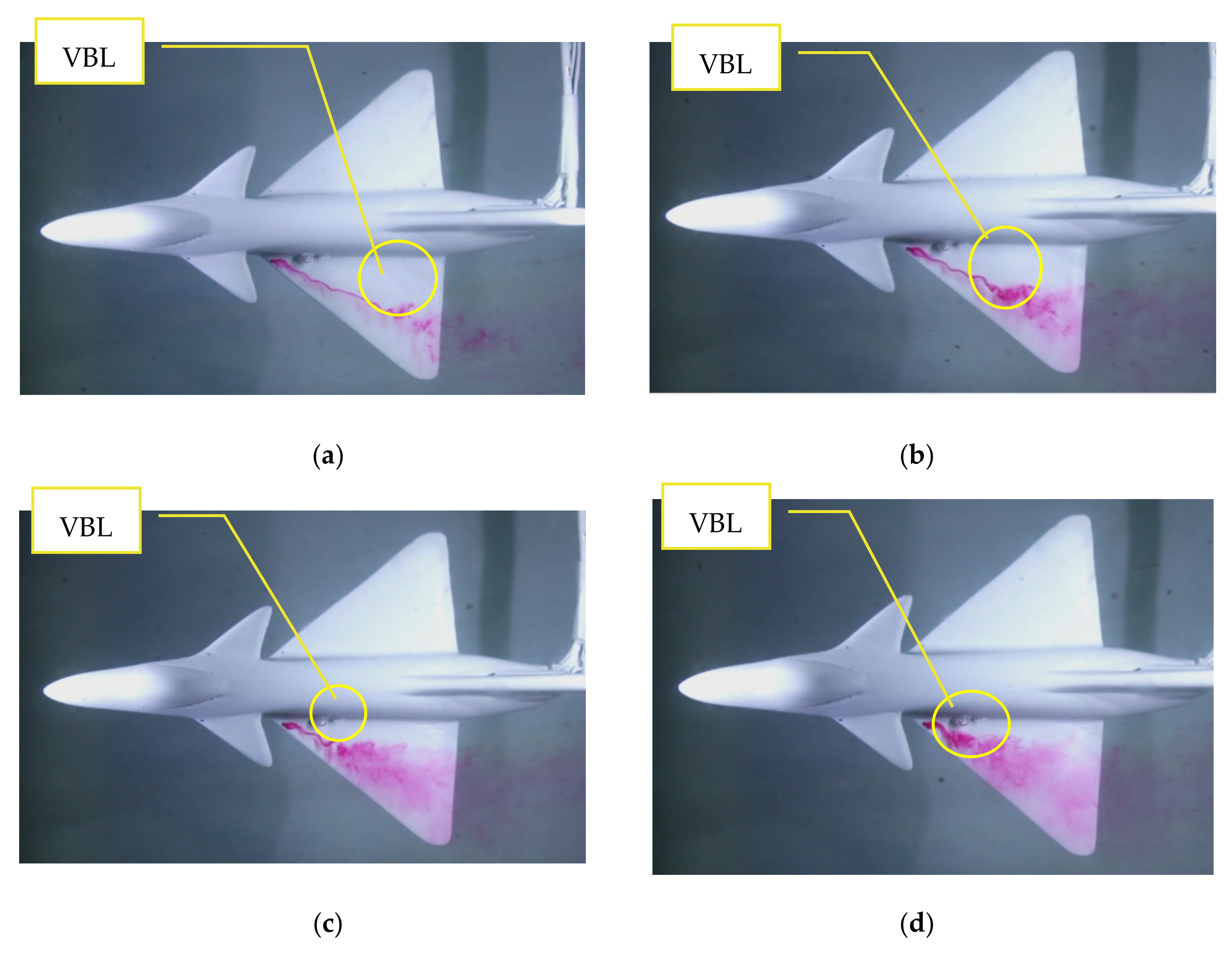
Figure 7 show the J-10, EF-T, and SU-30 aircraft models’ visualization results using water tunnel visualization techniques for AoA 20° to 50°. Ink was injected at the front of the wing by adjusting the injection output speed to the water flow’s pressure and velocity. The ink came out through the ink injection hole and formed a flow line following the water flow towards the wing’s back. The ink line that occurred indicated a vortex core from the front of the main wing. Under certain conditions, the ink line broke, which indicated a vortex breakdown occurred.
Figure 5 shows that in AoA 20°, a vortex core formed starting from the front end of the main wing of the J-10 model to the length x/C
root = 0.7. At the x/C
root distance, the ink line broke and showed the occurrence of vortex breakdown. The more AoA rose, the location of the vortex breakdown progressed. At AoA 30° the location of vortex breakdown occurred at x/C
root = 0.55 as well as at AoA 40° occurred at x/C
root = 0.4 and AoA 50° occurred at x/C
root = 0.25.
Figure 6 shows the formation of the vortex core on the SU-30 aircraft model. At AoA 20°, the vortex core formed on the main wing until the rear approached the value x/C
root = 0.82. Likewise, due to an increase in AoA caused the location of the vortex breakdown to move forward, which was marked by damage to the ink line. The location of vortex breakdown at AoA 30°, 40° and 50° occurred at x/C
root value = 0.65; 0.45 and 0.27.
Meanwhile,
Figure 7 presents a visualization of the vortex core on the EF-T airplane model. At AoA 20, the well-formed vortex nucleus started from the leading edge to the back and underwent vortex breakdown at x/C
root = 0.9. Increased AoA made the location of the vortex breakdown more advanced. At AoA 30, the location of vortex breakdown occurred at x/C
root = 0.72. Furthermore, in AoA 40° and 50°, vortex breakdown occurred faster with the location of vortex breakdown at x/C
root = 0.41 and 0.12.
The vortex breakdown explains how the aircraft model’s vortex lift character due to AoA changed. In conditions where vortex breakdown was already very dominant, it shows the loss of most of the lift force called the stall. The vortex breakdown (VBL) location between the three models ranging from AoA 0° to 80° is presented in
Figure 8. The size of the vortex core in the EF-T model had a longer tendency than the J-10 and SU-30 models at low attack angles (0–30°). On subsequent AoA enhancements, EF-T quickly deteriorated the vortex core, and the location of vortex breakdown advanced rapidly compared to other models. While in the SU-30 and J-10 models, the slower vortex breakdown occurred up to AoA 55°. At AoA 60°, it can be seen that VBL was very close to the leading edge of the wing (leading edge) on all models. This condition indicates that the AoA starting at 60° experienced a loss of lift or stall.
Figure 9 shows the CFD simulation results from the J-10, SU-30, and EF-T model for AoA 40°.
Figure 9a,c,e show the CFD visualization results on vortex core formation on the wings and canards aircraft based on Q-Criterion. The definition of Q-criteria is based on the value of the strain rate tensor and tensor vorticity and defines vortices as the area where the magnitude of the vortices is greater than the strain rate [
50], written as:
where
S is the strain-rate tensor, and
Ω is the vorticity tensor. We will get an area with a certain vortex flow strength that indicates a vortex nucleus’s existence from the determined criteria. The simulation results show that the vortex core is formed from the wing’s front corner and flowing along the edge of the wing. In the middle part of the chord root, the vortex core area experiences a sudden change in the nucleus structure and subsequently suffers damage. The higher the AoA, the core area of the vortex, based on the Q-criterion, will appear larger area, but the strength was weakened, and the location of vortex breakdown advanced. At certain AoA, the vortex breakdown location was at the front end of the main wing. This AoA condition shows that the vortex breakdown was dominant so that the lift force decreased a lot. The AoA condition was different in aircraft models. In the EF-T model, it occurred faster than in the SU-30 and J-10.
Figure 9b,d,f presents the pressure contours on the wing cross-section and wall shear streamline on the wing surface of model J-10, SU-30, and EF-T planes. Visualization of pressure contours also shows the formation of the vortex core. The center of the contour has a higher velocity than the freestream. At the rear, the contour core velocity was seen to enlarge the contoured core. The wall-shear streamline shows the flow projection line on the wing surface. At low AoA, the flow path tended to go straight and streamline to the back of the wing. It was just that on the end of the wing began to occur deflection. The bend location had the same position as the core speed contour rupture. It was at this location that vortex core damage could be indicated.
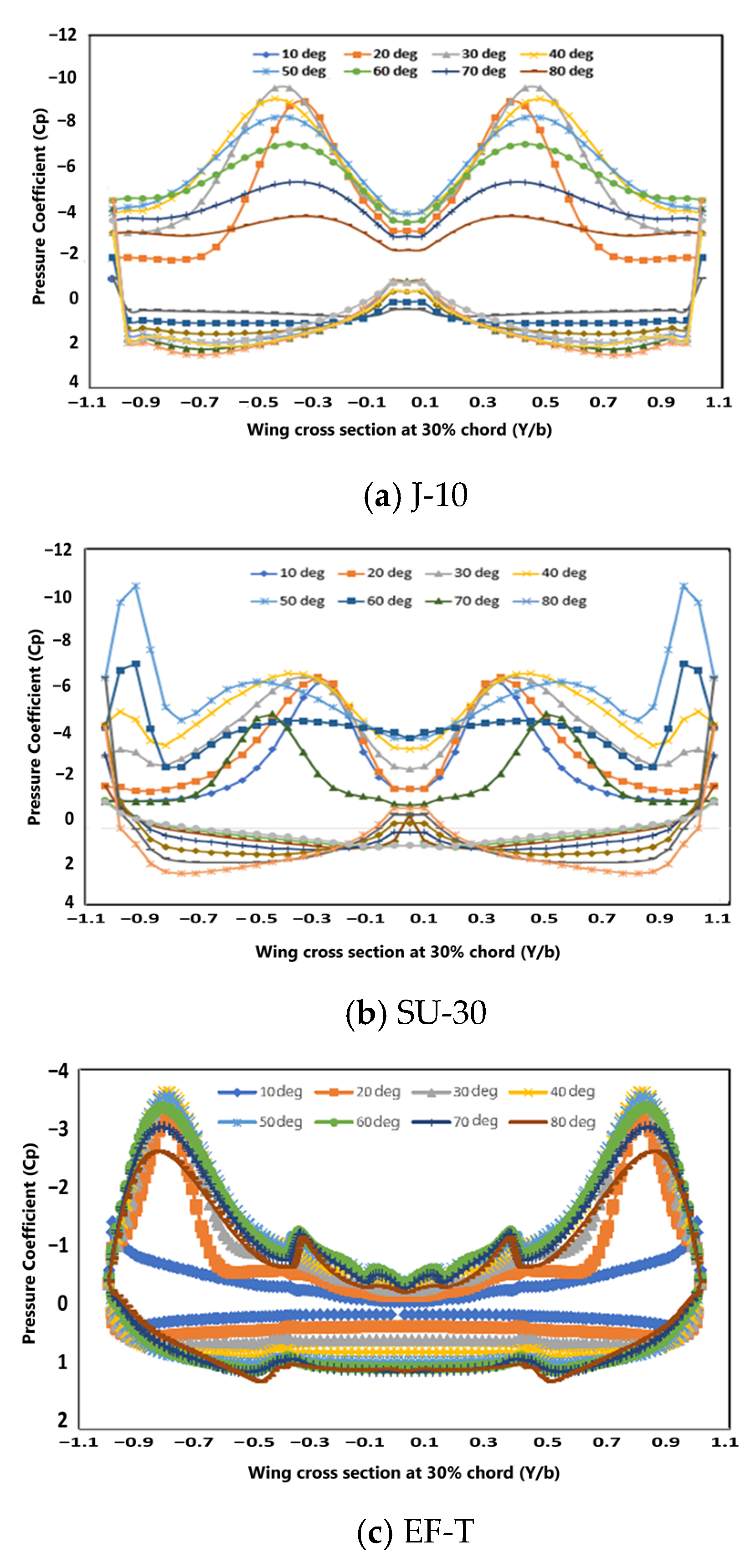
Figure 10 shows the pressure distribution on the 30% cut surface of the wing root chord for the J-10, SU-30, and EF-T aircraft models. Pressure distribution indicates where the center of the lift force is formed. The location of the graph that produces negative pressure is where the vortex core is formed. The pressure difference between the upper and lower wings will cause lift.
At locations of 30% of the wing root chords and AoA, up to 60° are still able to form a lift force, which is indicated by the shape of the pressure distribution that again shows high negative pressure on the upper surface of the wing. Above AoA 60°, the negative pressure distribution has begun to slope and does not show a negative pressure difference. This pressure distribution shows that the vortex core is not formed so that the lifting force will also be reduced or even disappear.
In the J-10 model (See
Figure 10a), the value of the negative pressure coefficient (Cp) was very low, reaching less than −8 at low angles of attack (AoA < 30°). Furthermore, an increase in AoA will reduce the value of Cp significantly. While in the SU-30 model (see
Figure 10b), negative Cp formation was higher than other models at low AoA, which was around −7. However, at an intermediate AoA (20–50°), the largest negative pressure distribution tends to be stable for changes in AoA to 50°. In the EF-T model, the Cp value tended to be lower than the other models for all AoA. In comparison, the location of the negative pressure peak for model J-10 tended to center and approach the fuselage, while in the SU-30 and EF-T models, more to the edge of the wing.
Figure 11a,d,g showed velocity distribution through the length of the vortex core models J-10, SU-30, and EF-T. The figure presents the non-dimensional velocity (U
c/U
∞) at the core of the vortex. The formation of a vortex nucleus will cause a velocity at the center of the vortex is higher than freestream, so the value of U
c/U
∞ > 1 indicates the existence of a vortex nucleus.
Figure 11a is shown that on the plane model J-10 to the AoA 10° distribution of velocity experienced a rise and descended as slowly. The pictures can also predict the occurrence of damage to the core vortex, the current value of U
c/U
∞ < 1. At the higher AoA increase, the distribution decline was faster and more advanced. This shows the location of the vortex breakdown, which was more advanced with the increase in AoA. At AoA 50°, the velocity distribution value was below one, indicating vortex breakdown dominance. At AoA 60°, the value of the speed distribution since the front was already low. It showed no formation of core vortex and already the occurrence of vortex breakdown.
In the SU-30 model, pressure distribution characteristics in non-dimensional velocity (Uc/U∞) were almost the same. At low AoA, the value of Uc/U∞ increased and slowly decreased until it reaches less than one at the back of the wing. An increase in AoA made the location of the Uc/U∞ < 1 value moving forward. However, on the SU-30 aircraft model, the rise in Uc/U∞ values on the front was almost the same value. The highest AoA still formed the vortex nucleus at AoA 50°, while at AoA 60°, it had not demonstrated the vortex nucleus because since from the front, the value of Uc/U∞ was already low. Meanwhile, EF-T models tended to have lower non-dimensional velocity and faster decrease for AoA increase.
The vortex core position can also be presented in a vortex line, as shown in
Figure 11. The paths for the J-10, SU-30, and EF-T models are presented transversely (spanwise) and vertically (height). In the spanwise path, the vortex lines formed show that the three models had trajectories for almost the same. However, the SU-30 model had a more outward trajectory (widening) than the other two models. While for the height of the vortex line trajectory, it was seen that increasing AoA on the J-10 and EF-T models increased the height of the vortex line trajectory. While in the SU-30 model, the increase in AoA did not significantly increase the vortex line trajectory’s height, except after AoA was 60°. In general, the track’s height in the SU-30 model was lower than in the J-10 and EF-T models.
4. Discussion
The results of experiments and simulations on J-10, SU-30, and EF-T with standard canard configurations show that the three models had different flow characteristics. Differences in the position of the canard against the main wing produced different interactions. The canard position on the J-10 and EF-T models had almost the same character at low AoA. The canard position at the front and top resulted in a greater lift, especially in low AoA (<20°). Whereas in the SU-30 model, which had a canard position right in front (coincide) of the main wing, Cl’s value was smaller than the other models. The presence of space between the canard and the main wing on J-10 and EF-T formed the vortex core from the wing’s front end. In the SU-30 model, the vortex core formation was shifted from the front end to the rear of the leading edge due to the narrow area between the canard wings, which resulted in a pressure difference. This can be seen in the figure of velocity distribution in small AoA. The gap effect at low AoA for the J-10 and EF-T models was greater to produce the Cl than the SU-30 model, as seen in the Cl-AoA graph.
For higher AoA (20–35°), the fuselage’s tilt towards the wind made the area between the canard and wing more open. In the SU-30 model, the vortex core formation already began to occur from the front end of the wing so that the lifting force (Cl) became higher than other models. The fuselage’s inclination increased with the increase in AoA on the J-10 model, causing the vortex core that occurred from the canard to be higher above the main wing. This was evidenced by the higher altitude trajectory and caused the concentration of lift to be reduced. This condition’s effect was reduced flow interaction so that at AoA 30–50°, the Cl value of J-10 and EF-T models were smaller than the SU-30 model.
At very high AoA (>50°), it can be seen that vortex breakdown occurred from the front of the wing. This was demonstrated by both the visualization of the water tunnel and CFD, the direction of the wall shear streamline, the breakdown of the velocity contour center, and the non-dimensional velocity distribution (Uc/U∞). This happened to all aircraft models. The decrease in Cl value at AoA was very high faster in SU-30 than J-10 due to the closer canard distance and coincided with the main wing, making it more difficult for airflow to form the vortex nucleus at the end because the canard blocks the flow. In contrast, in the EF-T model, because the distance of the canard to the main wing was horizontally farther away, the interaction at high AoA was also small, so stall delay was reduced.
The flow dynamics analysis results show that different canard configurations in several aircraft models will produce different flow forms. This difference in flow also produced different aerodynamic characters. In various references about canards, the advantages of canards have been mentioned to increase the lift coefficient. In this study, the flow character and the lift coefficient increase were significantly influenced by the canard’s configuration and the attack segment’s angle. A small angle of attack was more optimal in canard configurations spaced with the main wing than the other canard configurations, the canard’s position above or in front of the main wing. The vortex-core formation in the wing began at the front end of the wing. The strong vortex on the canard also interacted quite strongly with the rolled-up vortex on the wing. Meanwhile, in the pair of wings and canard, which coincided, the wing vortex’s rolled-up formation tended to shift sideways and resulted in a lower lift than the canard’s position above the wing. However, at a higher angle of attack, the coincided canard position had a good aerodynamic character because the strong vortex interaction of the canard and the rolled vortex of the wing was stronger due to the opening of the gap between the wing and the canard when AoA increased.
The difference in flow characteristics gave each aircraft configuration advantages and disadvantages so that the canard aircraft’s optimal character was also determined in the flight segment or flying concept being designed. This research still did not include the canard’s flexible deflection function as in the Sukhoi SU-30 aircraft. It is possible to have better aerodynamic characteristics by utilizing flow engineering due to canard deflection, although in manufacturing, it becomes more complex [
24].
In general, the results obtained from this study show the interaction of flow and aerodynamic character on the aircraft due to the influence of different canard positions. This study’s resulted were following some previous studies related to the canard effect’s characteristics. The position of the canard at the top resulted in a higher lift at low attack angles. The more AoA rose, the canard’s location, which was close to the main wing, gave better Cl results.


 ,
, 


