Article

The Heat Transfer in Plate Fin Heat Exchanger for Adsorption Energy Storage: Theoretical Estimation and Experimental Verification of the Methodology for Heat Accumulation Process

Boreskov Institute of Catalysis, Lavrentiev Ave. 5, Novosibirsk 630090, Russia
*
Author to whom correspondence should be addressed.
Submission received: 21 July 2023 / Revised: 31 July 2023 / Accepted: 8 August 2023 / Published: 10 August 2023
(This article belongs to the Collection Challenges and Advances in Heat and Mass Transfer)

Abstract

:
Adsorption energy storage is a promising resource-saving technology that allows the rational use of alternative heat sources. One of the most important parts of the adsorption heat accumulator is the adsorber heat exchanger. The parameters of heat transfer in this unit determine how fast heat from an alternative energy source, such as the Sun, will be stored. For the design of adsorption heat accumulators, plate fin heat exchangers are mainly used. In this paper, the procedure for the estimation of the global heat transfer coefficient for the adsorber heat exchanger depending on its geometry is considered. The heat transfer coefficient for a LiCl/SiO2 sorbent flat layer under conditions of heat storage stage was measured. Based on these data, the global heat transfer coefficients for a number of industrial heat exchangers were theoretically estimated and experimentally measured for the adsorption cycle of daily heat storage. It was shown that theoretically obtained values are in good agreement with the values of the global heat transfer coefficients measured experimentally. Thus, the considered technique makes it possible to determine the most promising geometry of the plate fin heat exchanger for a given adsorption heat storage cycle without complicated experiments.

1. Introduction

The deteriorating ecological situation on the planet is attracting more and more attention from the world community [1,2,3]. In order to avoid a catastrophe, humankind needs to reconsider its attitude toward the consumption of natural resources and pay special attention to the development of energy-saving technologies [4,5,6,7]. Reusing waste heat from industry and transport is very important as well [8]. Adsorption heat storage is a technology that allows the use of heat from alternative energy sources (geothermal energy, solar energy) and waste heat from industry and transport [9,10,11]. The technology is based on a reversible sorption/desorption process accompanied by appropriate thermal effects. The porous sorbent is dried using a source of low-grade heat, such as solar energy during the day. Then, the dry sorbent can retain the stored heat indefinitely. If it is necessary to release heat (for example, at night, when it is impossible to use solar energy directly), the sorbent can be brought into contact with the vapors of the working fluid. Thus, the advantages of adsorption heat storage are (1) the ability to harmonize in time the processes of heat generation and consumption (to store heat during the day and use it at night) and (2) the possibility of using low-grade heat below 100 °C. Indeed, for the daily cycle, sorbent should be regenerated at a temperature of 70–80 °C, which can be supported by simple solar collectors [12,13]. The thermodynamic cycle of such a process (Figure 1) is determined by the conditions under which the device will operate (evaporator temperature Tev, condenser temperature Tcon, regeneration temperature Treg, and adsorption temperature Tads) and consists of four stages [14]: (1) the sorbent regeneration stage (isobaric heating 1–2) at the temperature of available low-potential heat Treg; (2) the isosteric cooling stage (the sorbent is disconnected from the tank with the working fluid and the amount of liquid absorbed by the sorbent does not change; therefore, line 2–3 on the cycle is the isostere line of composition constancy); (3) the heat generation stage initiated by a sharp change in pressure over the sorbent (3–4); (4) isosteric heating of the sorbent (3–4). Thus, in the heat storage cycle, the driving forces of the key stages are characterized by different factors: desorption during heat storage is initiated by a sharp change in the temperature of the sorbent, and heat release by a sharp change in pressure over the sorbent.
Thermal engineering related to energy-saving applications needs fast and accurate prediction for complex heat transfer problems [15]. To increase the efficiency of adsorption heat transformers, it is necessary to optimize the adsorber heat exchanger (AHex), which is one of the main elements of the device [16,17,18,19]. The effects of the adsorber heat exchanger’s material and the fin’s geometry on the AHex performance were analyzed in [20]. It was shown that aluminum is a good candidate for AHex construction due to its lower density and volumetric heat capacity compared to copper. In [20], it was demonstrated that finned flat tube (FFT) heat exchangers are characterized by a higher power normalized per volume of AHex than annular finned tube (AFT) heat exchangers. This is why FFT AHexes are so popular for adsorption heat transformation applications [21,22,23,24,25,26]. On the other hand, improvement of device performance by optimization of AHex geometry can be achieved [27]. In order to evaluate the efficiency of a heat exchanger loaded with a sorbent in a given process, it is necessary to know (1) the geometry of the heat exchanger, (2) the heat transfer coefficient in the metal–sorbent system, and (3) the heat transfer coefficient in the metal–heat carrier system. Theoretically, knowing these parameters, one can estimate the global heat transfer coefficient (UA) of an adsorber heat exchanger of a given geometry, and choose the optimal one. It is important to note that, in [28], the possibility of using the heat transfer coefficient measured for the flat layer of sorbent to be used for the calculation of UA was demonstrated for air conditioning applications. However, such heat transfer coefficients for the processes of adsorption heat transformation known from the literature are determined for processes characterized by exponential kinetic curves [29,30,31]. In this paper, another method for determining the metal–sorbent heat transfer coefficient, which is suitable for both exponential and non-exponential kinetics, was considered: the linearization of the initial part of the desorption kinetic curve.
The purpose of this work was to verify the procedure of optimizing the AHex geometry for the process of adsorption heat storage (daily cycle). For the cycle perspective, a working pair “composite sorbent LiCl/SiO2–methanol” was considered. The sorbent can be regenerated at 70–80 °C under conditions of a daily heat storage cycle and is able to accumulate a high amount of low potential heat [32]. A number of FFTs of heat exchangers of various geometries were considered, and a procedure for the theoretical calculation of the global UA coefficient for heat exchangers of various geometries is proposed. To verify the procedure used, direct measurements of the UA coefficients for three heat exchangers were carried out. It is important to note that a complex analysis of both theoretical predictions and direct measurements of the global heat transfer coefficient of real heat exchangers under conditions of the daily heat storage process was carried out for the first time.

2. Theoretical Consideration

In an FFT heat exchanger, the granules of sorbent are placed between the fins and the channels through which the heat transfer fluid (HTF) circulates (Figure 2). The requirements for an AHex that will be optimal for the charging (desorption) stage of the sorption heat storage cycle can be formulated in such a way that it should demonstrate the highest thermal power per unit of its volume. Indeed, the faster the heat is accumulated by the sorbent (stage 1–2, Figure 1), the less time is required to charge the heat accumulator. There are three main ways how one can determine the relevant control volume of AHex [33]: “comprehensive”, “Hex-only”, and “Hex core only”. In this work, the third variant, “only core of heat exchanger”, was considered.
The main thermophysical characteristic of heat exchangers is the global coefficient, UA. This characteristic allows us to quantify the amount of heat transferred from medium 1 to medium 2 at a fixed temperature difference between them [34,35]. For FFT, AHex UA can be calculated using the overall heat transfer coefficient U (W/m2K) and the channel area A as the parameters (UA = U٠A). The U coefficient can be found by using the following expression [34,35]:
U = 1 h 1 + δ w a l l λ w a l l + 1 h 2 ( 1 + E ( K 1 ) 1 ,
where h1 and h2 are heat transfer coefficients between HTF and the channel’s wall and between the sorbent and metal of AHex, respectively; δwall is the thickness of the aluminum wall of the AHex channel; λwall is the thermal conductivity of aluminum (λwall = 200 W/(mK)); K is the finning coefficient; E is the coefficient of fin efficiency [34].
The coefficient of efficiency E determines the difference in the removal of heat between the ideal isothermal fin and the real non-isothermal fin [34]:
E = t a n h ( 0.5 H f 2 h 2 / δ f λ w a l l 0.5 H f 2 h 2 / δ f λ w a l l ,
where δf is the fin’s thickness, λwall is the aluminum thermal conductivity. The h1 coefficient between HTF and the channel’s wall can be determined as follows:
h 1 = N u · λ w H c h ,
where H’ch is the internal channel’s height, λw is the HTF thermal conductivity (λw = 0.67 W/mK at 80 °C), Nu is the Nusselt number. For laminar flow, the Nusselt number for a flat channel is about 8 [36].
As it was mentioned above in (1), the h2 coefficient measured for a flat layer can be used successfully [28]. The h2 coefficient for a flat layer can be found from kinetic measurements under conditions of the cycle (stages 1–2, Figure 1). In this work, the daily storage cycle typical for the off-season with the following parameters was considered (Figure 1): (1) daytime temperature of the environment Tcon = 15 °C, (2) nighttime temperature of the environment Tev = 5 °C, (3) regeneration temperature Treg = 80 °C, (4) temperature desired by the consumer Tad = 30 °C. In the cycle, the heat storage stage is initiated by a temperature jump at constant pressure (stage 1–2 Figure 1). The maximum specific power, in this case, can be expressed as follows:
W m a x = h 2 S Δ T / m ,
where m—sorbent mass, h2—heat transfer coefficient in the sorbent–metal system, S—sorbent–metal contact area, ΔT—temperature driving force of heat transfer. So, for h2 determination, the maximum specific power at different driving forces should be measured. After that, the h2 coefficient can be determined graphically from the dependence “maximal specific power Wmax vs. ΔT” as the slope of the graph. Temperature driving force can be found from sorption equilibrium “sorbent—working fluid”. In this study, composite sorbent on the base of a porous matrix impregnated with inorganic salt (LiCl/SiO2) was used. “Salt inside porous matrix” (CSPM) materials are very promising for adsorption heat transformation due to their high sorption capacity and low regeneration temperature under appropriate adsorption cycle conditions [37,38,39,40]. Another advantage of CSPM composites is their high energy storage capacity due to the chemical reaction between the salt and working fluid vapor. Generally, the thermal effects accompanying such reactions are greater than the thermal effects that can be provided by materials that store sensible heat [41] (e.g., for concrete) or latent heat [42] (e.g., heat of a phase transition for phase change materials [43,44,45,46]). The CSPM composites demonstrate stepped isotherms [32,47] corresponding to the abovementioned chemical reaction between the salt in the matrix pores and working liquid vapors. Methanol was used as a working liquid. The reaction begins at temperature T* which can be found from the sorption equilibrium data of the LiCl/SiO2–methanol system [48]. The sorption isobar (Figure 3) at constant condenser pressure (in this work Pcon = 96 mbar at Tcon = 15 °C) can be calculated from the dependence “sorption capacity w—sorption potential ΔF” [48] using a combination of two expressions: (1) desorption boundary Polanyi potential ΔFdes (Figure 1) and the Clausius–Clapeyron equation. Figure 3 evidences that the temperature of the step corresponding to the chemical reaction is about T* = 48 °C. Thus, the temperature driving force of the desorption in Equation (4) can be found as ΔT = Treg − T*.
Thus, all the parameters of (1), i.e., h1, h2, and E, needed to calculate the UA coefficient for AHex with known geometry can be found using the abovementioned procedure.

3. Materials and Methods

3.1. Adsorbent Synthesis

The sorbent was synthesized from pure matrix by the “incipient wetness” method [32]. The silica gel Davisil Gr. 646 with an average pore diameter of 15 nm, specific surface area of 300 m2/g, and specific pore volume of 1.18 cm3/g was dried to remove physically bound water at 160 °C for two hours. The impregnation solution was prepared using distilled water and lithium chloride (Aldrich, Burlington, MA, USA, 99.9%). The volume of the poured solution corresponded to the pore volume of the matrix. After impregnation, the sorbent was dried for two hours at a temperature of 160 °C. The mass content of salt was determined by the difference in the weight of the initial matrix and the composite after drying. The salt content in the sample was 21 wt %. In order to obtain granules 0.4–0.5 mm in size, the prepared composite was sieved.

3.2. Heat Transfer Coefficient Measurements

To measure the heat transfer coefficient h2 metal–sorbent (flat layer), the Large Temperature Jump (LTJ) method [49] was used. The LTJ method simulates the operation of a real device for adsorption heat transformation in a laboratory. Desorption initiated by a sharp change in the temperature of the metal support with the sorbent was carried out at a constant methanol pressure of about Pcon = 96 mbar. Such conditions are very close to the isobaric stage during the heat storage process in the considered cycle. A flat layer of sorbent granules with a grain size of 0.4–0.5 mm, about 100 mg, was investigated. The switching between hot and cold thermostats resulted in a sharp change in the metal support temperature where the sorbent was located. The initial temperature was always constant and amounted to 41 °C. The final temperature of the metal support took the following values: 70, 75, 80, 85 °C. During the desorption process, a change in pressure ΔP was registered. This kind of measurement simulates the isobaric desorption stage of the cycle (1–2, Figure 1), because the reactor with metal support and sorbent was connected with a huge buffer vessel (with volume V) maintaining quasi-isobaric conditions. After that, using the ideal gas equation, the change in pressure ΔP was converted into the amount of sorbed methanol Δm(CH3OH) = μ(CH3OH)٠ΔP٠V/(RT). The amount of methanol (Δm) multiplied by the isosteric heat of methanol sorption (41.8 kJ/mol for LiCl/SiO2 [32]) gives the thermal effect of the desorption process Q. The slope of the initial part of the dependence “Q vs. time” gives the maximal power of desorption, which can be used for the h2 calculation with Equation (4).

3.3. AHex Testing

The experimental setup consists of a vacuum chamber in which the AHex is placed, a condenser that provides constant pressure in the system, two thermostats, a pump, and a system of valves (Figure 4). The switching of HTF flow from a cold thermostat to a hot one makes it possible to simulate the stage of heat accumulation. The experimental setup and measurement procedure are described in more detail in [50]. The main principle of AHex testing under the realistic conditions of the desorption stage 1–2 of the considered cycle is measuring the temperature difference between inlet and outlet HTF temperature (ΔT, Figure 4). The power required to heat up the AHex and desorb methanol is proportional to ΔT:
M = Δ T f w C p w ρ w
where fw is the water flow (fw = 202 L/h), Cpw is the heat capacity of water, ρw is the density of water.
In order to separate the contribution of the desorption process alone and the contribution of the heat capacity of AHex from the total temperature response (ΔT), it is necessary to carry out a blank experiment. During the blank experiment, the condenser is disconnected from the vacuum chamber with AHex and desorption does not occur. By subtracting the blank data from the kinetic curve recorded in the presence of methanol vapor, the contribution of desorption to the response can be extracted [50].
The maximum value of the difference between signals of the blank experiment and experiment in the presence of methanol vapor (ΔΔT = ΔTkinetic − ΔTblank) gives a possibility to obtain the maximum power of the desorption process. The relative accuracy of heat flux measurements was 10%.
This experimental procedure also makes it possible to estimate the time required for the regeneration of the sorbent and make conclusions about the prospects for the use of AHex under the given operation conditions.
By varying the final desorption temperature, one can change the driving force of desorption. This makes it possible to experimentally determine the global heat transfer coefficient UA for AHex. Indeed, the maximal power transferred from HTF to the sorbent is proportional to UA and the temperature driving force:
M m a x = U A ٠ Δ T
By plotting the dependence of the maximal power on the final desorption temperature, one can graphically determine UA as the slope of the graph “Mmax vs. Tdes”.

4. Results

4.1. Heat Transfer Coefficients Measurements

Figure 5a shows that with the rise in desorption temperature, the desorption rate increases too. In order to find maximal power Wmax, the linear approximation of the graph “heat Q vs. time” was used (see insert in Figure 5a). With the use of expression (4), the heat transfer coefficient h2 was found as the slope of graphical dependence of the maximal power Wmax on the temperature driving force (ΔT = Treg − T*) (Figure 5b).
The heat transfer coefficient h2 between metal and sorbent was found as the slope of plot “ Wmax vs. ΔT “ h2 = 125 ± 10 W/(m2K). This value of h2 was used for further calculation of U coefficients according to Formula (1) and appropriate UA coefficients. The UA coefficients were estimated for eight pieces of different commercial FFT radiators with the same core volume of 140 cm3 (Table 1).
Calculated values of UA were divided into three groups (Figure 6): (1) high UA (Figure 6, green area), (2) middle UA (Figure 6, yellow area), (3) low UA (Figure 6, red area). The heat exchangers № 4, № 5, № 7, and № 8 demonstrate the highest theoretical values of UA among all the considered geometries. This is in line with theoretical considerations presented in [28], where the analysis of UA coefficient sensitivity to changes in the parameters of the heat exchanger was made. It was shown that the global heat transfer coefficient is most sensitive to the area of the primary surface of the channels, the metal–sorbent heat transfer coefficient, the height of the fins, and the distance between them. In accordance with this theoretical consideration, Table 1 shows that heat exchangers from the first group (green area Figure 6) demonstrate the lowest distance between fins.
From each group, one core geometry was chosen for making the direct measurements of the UA coefficient under conditions of the heat storage stage. The small AHexes were manufactured with the use of cores: №5, №3, and №6.

4.2. Global Heat Transfer Coefficient Measurements

The driving force of desorption arose due to AHex switching from the cold thermostat to the hot one (41 °C → 80 °C) while methanol pressure was P = 96 mbar. It turned out that in a blank experiment (in the absence of methanol vapors), the temperature of the water leaving the AHex starts to rise a bit later than the temperature of the inlet water (Figure 7a); however, the curve profiles are similar. In about 30 s, the temperatures of the inlet and outlet water in the blank experiment become close. In the presence of methanol vapor, the temperature profiles for inlet and outlet water are significantly different (Figure 7b) due to the desorption of methanol from the composite. This difference manifests itself as a shoulder on the temperature profile of outlet water (Figure 7b). More time (about 100 s) is required to reach the stationary state in the presence of methanol vapor.
By subtracting the outlet water temperature from the inlet water temperature, the temperature response ΔT = Tinlet – Toutlet can be found both for blank and kinetic experiments (Figure 8a). This desorption process manifests itself as a shoulder on the profile of the ΔT curve (black line Figure 8a). The resulting kinetic curve related to the process of methanol desorption can be obtained by subtracting the blank curve from the kinetic curve measured in the presence of methanol Δ(ΔT) = ΔTkinetic – ΔTblank (Figure 8b).
From the value of ΔTmax (Figure 8b), the maximum power was calculated (right axis). Also, Figure 8b evidences that a tenfold decrease in power occurs within ca. 60 s of beginning the process. This shows that the sorbent can be regenerated very quickly.
For all the studied AHexes, the dependencies of maximal desorption power were measured as a function of time under various experimental conditions. Integrating the signal related to desorption allows us to calculate the thermal effect of desorption:
G des = ρ C p f Δ ( Δ T ) d t
where ρ is the density, Cp is the heat capacity, f is the flow rate of the HTF (water). For different heat exchangers, Gdes is about 30 kJ (Table 2). The close values of Gdes are caused by the fact that the core volumes of considered AHexes are the same (140 cm3). That is why the masses of the loaded adsorbent were close to each other (about 40 ± 1 g).
According to Formula (6), the power Mmax is proportional to the global heat transfer coefficient UA. The slope of the linear dependences gives the experimental value of the UA for all investigated AHexes (Figure 9). To verify the theoretical calculations of the UA coefficient, the obtained experimental values UAexp were compared with the theoretically estimated values UAtheor (Table 2).
From Table 2, it can be seen that the theoretically calculated values of UA (Figure 6) correlate well with the values obtained experimentally. Thus, AHex №5 demonstrates the highest value of UA among the tested heat exchangers, and the highest value of power as well. The thermal effects of desorption Gdes for different investigated AHexes are close to each other. The times corresponding to the degree of conversion of 0.9 do not exceed 5 min, which makes it possible to expect a fast regeneration of the sorbent. However, the higher the UA, the faster desorption proceeds.
Thus, it is shown that Formula (1) for calculating UA can be used to assess the prospects of AHex of known FFT geometry for adsorption heat storage.

5. Discussion

Having analyzed the data of direct measurement of the global heat transfer UA coefficients for a series of heat exchangers, one can conclude that the highest UA coefficient was shown by AHex № 5 and the lowest by AHex № 6, which is consistent with the results of the theoretical calculations. AHex №3 demonstrates an intermediate value, which is in line with the theoretical predictions. It is interesting to note that the desorption temperature at which the observed process power becomes zero (intersection of linear approximations with the X-axis in Figure 9) is very close to the reaction temperature obtained from the equilibrium data T* = 48 °C (Figure 3) and is independent of the heat exchanger geometry. Such consistency of data obtained by different methods confirms their correctness. The correspondence between the theoretical and directly measured heat transfer coefficients for heat exchangers of various geometries allows us to conclude that the use of Formula (1) is correct for expressly estimating the global heat transfer coefficient of heat exchangers of various geometries for the process of adsorption heat storage. The volumetric heat transfer coefficient for heat exchanger No. 5 showed the highest UAV = 200 W/Kdm3. This result exceeds the values of this parameter reported in the literature, 50–100 W/(Kdm3) [51], which indicates the prospects of the selected working pair and geometry of FFT AHex. Taking into account the driving temperature difference in the considered cycle ΔT = Tdes − T* = 80 − 48 = 32 °C, one can easily calculate the maximal volumetric desorption power as high as 6.4 kW/dm3. The energy storage density normalized per core volume is 214 MJ/m3. This value exceeds the energy storage density for heat storage systems based on LiCl with the same regeneration temperature of 150–170 MJ/m3 [52].
It is important to note that the main aim of this article was to verify the procedure for UA prediction and choose the optimal AHex geometry for the adsorption daily storage cycle. The results show that varying the geometry can potentially improve the UA coefficient and the corresponding power of the process by 200% (ΔUA = (UAAHex№5 − UAAHex№6)/UAAHex№6 ٠ 100% ≈ 200%).

6. Conclusions

The heat transfer coefficients UA for FFT heat exchangers of various geometries presented in the paper were obtained both theoretically and by direct measurement under the conditions of an adsorption heat storage cycle. The consistency of the data obtained theoretically and by the method of direct measurements allows one to conclude that the proposed procedure for assessing the UA can be used to identify the optimal geometry of the FFT heat exchanger for the processes of adsorption heat storage without complicated sorption experiments. The values of the volumetric heat transfer coefficients indicate the prospects of the LiCl/SiO2–methanol pair.

Author Contributions

Conceptualization, A.G. and M.T.; methodology, M.T.; validation, S.S., A.L. and M.T.; formal analysis, A.L.; investigation, S.S.; resources, A.G.; data curation, A.G. and M.T.; writing—original draft preparation, A.G.; writing—review and editing, M.T.; supervision, A.G.; project administration, A.G.; funding acquisition, A.G. All authors have read and agreed to the published version of the manuscript.

Funding

The work was supported by the Russian Science Foundation project 21-79-10183.

Data Availability Statement

Data can be provided upon request.

Conflicts of Interest

The authors declare no conflict of interest.

Abbreviations

AHexheat exchanger
FFTfinned flat tube
HTFheat transfer fluid
LTJLarge Temperature Jump
Nomenclature
Aarea, m2
Cpheat capacity, J/(gK)
Eefficiency of the fin
Fadsorption potential, J/(molK)
fflow rate, L/h
Gheat, J
Hheight, m
hheat transfer coefficient, W/(m2K)
Kfinning coefficient
Mdesorption power, W
mmass, g
NuNusselt number
Ppressure, bar
Qthermal effect of desorption, J/g
Runiversal gas constant, 8.31 J/(molK)
Ssorbent–metal surface area, m2
Ttemperature, K, °C
ttime, s
Uoverall heat transfer coefficient, W/(m2K)
UAglobal heat transfer coefficient, W/K
Vvolume, dm3
Wspecific power, W/g
wuptake, g/g
Subscripts/superscripts
adadsorption
blankblank
concondenser, condensation
chchannel
desdesorption
evevaporator, evaporation
ffin
inletinlet
kinetickinetic
maxmaximum
outletoutlet
regregeneration
Vvolumetric
wwater
wallwall
*equilibrium
Greek symbols
δthickness
Δdifference, distance
λthermal conductivity, W/(mK)
τcharacteristic time, s
μmolar weight, g/mol
ρdensity, g/cm3

References

  1. Communication from the Commission to the European Parliament, the Council, the European Economic and Social Committee and the Committee of the Regions, Brussels. 16 February 2016. Available online: https://ec.europa.eu/energy/sites/ener/files/documents/1_EN_ACT_part1_v14.pdf (accessed on 21 July 2023).
  2. Meinshausen, M.; Jeffery, L.; Guetschow, J.; du Pont, Y.R.; Rogelj, J.; Schaeffer, M.; Höhne, N.; Elzen, M.D.; Oberthür, S.; Meinshausen, N. National post-2020 greenhouse gas targets and diversity-aware leadership. Nat. Clim. Chang. 2015, 5, 1098–1106. [Google Scholar] [CrossRef]
  3. Zhang, X.; Han, L.; Wei, H.; Tan, X.; Zhou, W.; Li, W.; Qian, Y. Linking urbanization and air quality together: A review and a perspective on the future sustainable urban development. J. Clean. Prod. 2022, 346, 130988. [Google Scholar] [CrossRef]
  4. Ononogbo, C.; Nwosu, E.; Nwakuba, N.; Nwaji, G.; Nwufo, O.; Chukwuezie, O.; Chukwu, M.; Anyanwu, E. Opportunities of waste heat recovery from various sources: Review of technologies and implementation. Heliyon 2023, 9, e13590. [Google Scholar] [CrossRef] [PubMed]
  5. Armeanu, D.S.; Joldes, C.C.; Gherghina, S.C.; Andrei, J.V. Understanding the multidimensional linkages among renewable energy, pollution, economic growth and urbanization in contemporary economies: Quantitative assessments across different income countries’ groups. Renew. Sustain. Energy Rev. 2021, 142, 110818. [Google Scholar] [CrossRef]
  6. Chen, J.; Zeng, Y.-S.; Yu, X.-Y.; Yuan, Q.; Wang, T.; Deng, B.; Yan, K.-L.; Jiang, J.-H.; Tao, L.-M.; Chen, C.-Z. A covering liquid method to intensify self-preservation effect for safety of methane hydrate storage and transportation. Pet. Sci. 2022, 19, 1411–1419. [Google Scholar] [CrossRef]
  7. Xue, W.; Wang, Y.; Chen, Z.; Liu, H. An integrated model with stable numerical methods for fractured underground gas storage. J. Clean. Prod. 2023, 393, 136268. [Google Scholar] [CrossRef]
  8. Lo, F.-Y.; Hsu, C.-H.; Chang, C.-T. Practicable total-site heat integration plan for retrofitting multiple heat exchanger networks. Chem. Eng. Res. Des. 2021, 174, 137–157. [Google Scholar] [CrossRef]
  9. Scuiller, E.; Bennici, S.; Dutournié, P.; Principaud, F. Towards industrial-scale adsorptive heat storage systems: From state-of-the-art selected examples to preliminary conception guidelines. J. Energy Storage 2022, 53, 105103. [Google Scholar] [CrossRef]
  10. Chen, Z.; Zhang, Y.; Zhang, Y.; Su, Y.; Riffat, S. A study on vermiculite-based salt mixture composite materials for low-grade thermochemical adsorption heat storage. Energy 2023, 278, 127986. [Google Scholar] [CrossRef]
  11. Luberti, M.; Gowans, R.; Finn, P.; Santori, G. An estimate of the ultralow waste heat available in the European Union. Energy 2022, 238, 121967. [Google Scholar] [CrossRef]
  12. Kalogirou, S.A. Solar thermal collectors and applications. Prog. Energy Combust. Sci. 2004, 30, 231–295. [Google Scholar] [CrossRef]
  13. Pandey, K.M.; Chaurasiya, R. A review on analysis and development of solar flat plate collector. Renew. Sustain. Energy Rev. 2017, 67, 641–650. [Google Scholar] [CrossRef]
  14. Gordeeva, L.; Aristov, Y. Adsorptive heat storage and amplification: New cycles and adsorbents. Energy 2019, 167, 440–453. [Google Scholar] [CrossRef]
  15. Wang, Y.; Yu, B.; Cao, Z.; Zou, W.; Yu, G. A comparative study of POD interpolation and POD projection methods for fast and accurate prediction of heat transfer problems. Int. J. Heat Mass Transf. 2012, 55, 4827–4836. [Google Scholar] [CrossRef]
  16. Jegede, O.O.; Critoph, R.E. Extraction of heat transfer parameters in active carbon–ammonia large temperature jump experiments. Appl. Therm. Eng. 2016, 95, 499–505. [Google Scholar] [CrossRef]
  17. Sharafian, A.; Fayazmanesh, K.; McCague, C.; Bahrami, M. Thermal conductivity and contact resistance of mesoporous silica gel adsorbents bound with polyvinylpyrrolidone in contact with a metallic substrate for adsorption cooling system applications. Int. J. Heat Mass Transf. 2014, 79, 64–71. [Google Scholar] [CrossRef]
  18. Radermacher, R.; Aute, V. Thoughts on the future of heat exchangers. Sci. Technol. Built Environ. 2016, 22, 1. [Google Scholar] [CrossRef] [Green Version]
  19. Grekova, A.; Krivosheeva, I.; Solovyeva, M.; Tokarev, M. Express Method for Assessing Optimality of Industrial Heat Exchangers for Adsorption Heat Transformation. Fluids 2022, 8, 14. [Google Scholar] [CrossRef]
  20. Khatibi, M.; Kowsari, M.M.; Golparvar, B.; Niazmand, H.; Sharafian, A. A comparative study to critically assess the designing criteria for selecting an optimal adsorption heat exchanger in cooling applications. Appl. Therm. Eng. 2022, 215, 118960. [Google Scholar] [CrossRef]
  21. Rogala, Z. Adsorption chiller using flat-tube adsorbers—Performance assessment and optimization. Appl. Therm. Eng. 2017, 121, 431–442. [Google Scholar] [CrossRef]
  22. Kowsari, M.M.; Niazmand, H.; Tokarev, M.M. Bed configuration effects on the finned flat-tube adsorption heat exchanger performance: Numerical modeling and experimental validation. Appl. Energy 2018, 213, 540–554. [Google Scholar] [CrossRef]
  23. Mahdavikhah, M.; Niazmand, H. Effects of plate finned heat exchanger parameters on the adsorption chiller performance. Appl. Therm. Eng. 2013, 50, 939–949. [Google Scholar] [CrossRef]
  24. Khatibi, M.; Kowsari, M.M.; Golparvar, B.; Niazmand, H. Optimum loading of aluminum additive particles in unconsolidated beds of finned flat-tube heat exchangers in an adsorption cooling system. Appl. Therm. Eng. 2021, 196, 117267. [Google Scholar] [CrossRef]
  25. Mikhaeil, M.; Gaderer, M.; Dawoud, B. On the application of adsorber plate heat exchangers in thermally driven chillers; An experimental and analytical study. Appl. Therm. Eng. 2023, 220, 119713. [Google Scholar] [CrossRef]
  26. Girnik, I.; Lombardo, W.; Sapienza, A.; Aristov, Y. Pressure- and temperature-initiated adsorption of water vapour in a finned flat-tube adsorber. Energy Convers. Manag. 2022, 258, 115487. [Google Scholar] [CrossRef]
  27. Verde, M.; Harby, K.; Corberán, J.M. Optimization of thermal design and geometrical parameters of a flat tube-fin adsorbent bed for automobile air-conditioning. Appl. Therm. Eng. 2017, 111, 489–502. [Google Scholar] [CrossRef] [Green Version]
  28. Grekova, A.; Tokarev, M. An optimal plate fin heat exchanger for adsorption chilling: Theoretical consideration. Int. J. Thermofluids 2022, 16, 100221. [Google Scholar] [CrossRef]
  29. Okunev, B.; Gromov, A.; Heifets, L.; Aristov, Y. Dynamics of water sorption on a single adsorbent grain caused by a large pressure jump: Modeling of coupled heat and mass transfer. Int. J. Heat Mass Transf. 2008, 51, 5872–5876. [Google Scholar] [CrossRef]
  30. Girnik, I.S.; Aristov, Y.I. Dynamic optimization of adsorptive chillers: The “AQSOA™-FAM-Z02—Water” working pair. Energy 2016, 106, 13–22. [Google Scholar] [CrossRef]
  31. Aristov, Y.I.; Glaznev, I.S.; Girnik, I.S. Optimization of adsorption dynamics in adsorptive chillers: Loose grains configuration. Energy 2012, 46, 484–492. [Google Scholar] [CrossRef]
  32. Gordeeva, L.G.; Freni, A.; Krieger, T.A.; Restuccia, G.; Aristov, Y.I. Composites “lithium halides in silica gel pores”: Methanol sorption equilibrium. Microporous Mesoporous Mater. 2008, 112, 254–261. [Google Scholar] [CrossRef]
  33. Gluesenkamp, K.R.; Frazzica, A.; Velte, A.; Metcalf, S.; Yang, Z.; Rouhani, M.; Blackman, C.; Qu, M.; Laurenz, E.; Rivero-Pacho, A.; et al. Experimentally Measured Thermal Masses of Adsorption Heat Exchangers. Energies 2020, 13, 1150. [Google Scholar] [CrossRef] [Green Version]
  34. Rohsenow, W.M.; Hartnett, J.P.; Cho, Y.I. (Eds.) Handbook of Heat Transfer, 3rd ed.; Mcgraw-Hill: New York, NY, USA, 1998; Volume 3. [Google Scholar]
  35. Ezgi, C. Basic Design Methods of Heat Exchanger. Heat Exchangers–Design, Experiment and Simulation; Murshed, S.S., Lopes, M.M., Eds.; IntechOpen: London, UK, 2017. [Google Scholar]
  36. Erdoğan, M.E.; Imrak, C.E. The Effects of Duct Shape on the Nusselt Number. Math. Comput. Appl. 2005, 10, 79–88. [Google Scholar] [CrossRef] [Green Version]
  37. Nguyen, M.H.; Zbair, M.; Dutournié, P.; Gervasini, A.; Vaulot, C.; Bennici, S. Toward new low-temperature thermochemical heat storage materials: Investigation of hydration/dehydration behaviors of MgSO4/Hydroxyapatite composite. Sol. Energy Mater. Sol. Cells 2022, 240, 111696. [Google Scholar] [CrossRef]
  38. Wei, S.; Zhou, W.; Han, R.; Gao, J.; Zhao, G.; Qin, Y.; Wang, C. Influence of minerals with different porous structures on thermochemical heat storage performance of CaCl2-based composite sorbents. Sol. Energy Mater. Sol. Cells 2022, 243, 111769. [Google Scholar] [CrossRef]
  39. Zhou, H.; Zhang, D. Investigation on pH/temperature-manipulated hydrothermally reduced graphene oxide aerogel impregnated with MgCl2 hydrates for low-temperature thermochemical heat storage. Sol. Energy Mater. Sol. Cells 2022, 241, 111740. [Google Scholar] [CrossRef]
  40. Jiang, L.; Lin, Y.; Liu, W.; Ma, Z.; Wang, R.; Zhang, X.; Roskilly, A. Thermophysical characterization of magnesium chloride and its application in open sorption thermal energy storage system. Sol. Energy Mater. Sol. Cells 2021, 236, 111528. [Google Scholar] [CrossRef]
  41. Kocak, B.; Fernandez, A.; Paksoy, H. Benchmarking study of demolition wastes with different waste materials as sensible thermal energy storage. Sol. Energy Mater. Sol. Cells 2021, 219, 110777. [Google Scholar] [CrossRef]
  42. Ye, C.; Zhang, M.; Yang, S.; Mweemba, S.; Huang, A.; Liu, X.; Zhang, X. Application of copper slags in encapsulating high-temperature phase change thermal storage particles. Sol. Energy Mater. Sol. Cells 2023, 254, 112257. [Google Scholar] [CrossRef]
  43. Saghir, M.Z. Enhanced Energy Storage Using Pin-Fins in a Thermohydraulic System in the Presence of Phase Change Material. Fluids 2022, 7, 348. [Google Scholar] [CrossRef]
  44. Hamad, A.J. Energy Saving and Charging Discharging Characteristics of Multiple PCMs Subjected to Internal Air Flow. Fluids 2021, 6, 275. [Google Scholar] [CrossRef]
  45. Bondareva, N.S.; Sheremet, M.A. Natural Convection Melting Influence on the Thermal Resistance of a Brick Partially Filled with Phase Change Material. Fluids 2021, 6, 258. [Google Scholar] [CrossRef]
  46. Jamalabadi, M.Y.A. Use of Nanoparticle Enhanced Phase Change Material for Cooling of Surface Acoustic Wave Sensor. Fluids 2021, 6, 31. [Google Scholar] [CrossRef]
  47. Lu, Z.; Wang, R. Study of the new composite adsorbent of salt LiCl/silica gel—Methanol used in an innovative adsorption cooling machine driven by low temperature heat source. Renew. Energy 2014, 63, 445–451. [Google Scholar] [CrossRef]
  48. Gordeeva, L.G.; Aristov, Y.I. Composite sorbent of methanol “LiCl in mesoporous silica gel” for adsorption cooling: Dynamic optimization. Energy 2011, 36, 1273–1279. [Google Scholar] [CrossRef]
  49. Aristov, Y.; Dawoud, B.; Glaznev, I.; Elyas, A. A new methodology of studying the dynamics of water sorption/desorption under real operating conditions of adsorption heat pumps: Experiment. Int. J. Heat Mass Transf. 2008, 51, 4966–4972. [Google Scholar] [CrossRef]
  50. Tokarev, M.; Aristov, Y. A new version of the Large Temperature Jump method: The thermal response (T–LTJ). Energy 2017, 140, 481–487. [Google Scholar] [CrossRef]
  51. Schnabel, L.; Füldner, G.; Velte, A.; Laurenz, E.; Bendix, P.; Kummer, H.; Wittstadt, U. Innovative Adsorbent Heat Exchangers: Design and Evaluation. In Innovative Heat Exchangers; Bart, H.J., Scholl, S., Eds.; Springer: Cham, Switzerland, 2018; pp. 363–394. [Google Scholar] [CrossRef]
  52. Liu, H.; Nagano, K.; Togawa, J. A composite material made of mesoporous siliceous shale impregnated with lithium chloride for an open sorption thermal energy storage system. Sol. Energy 2015, 111, 186–200. [Google Scholar] [CrossRef]
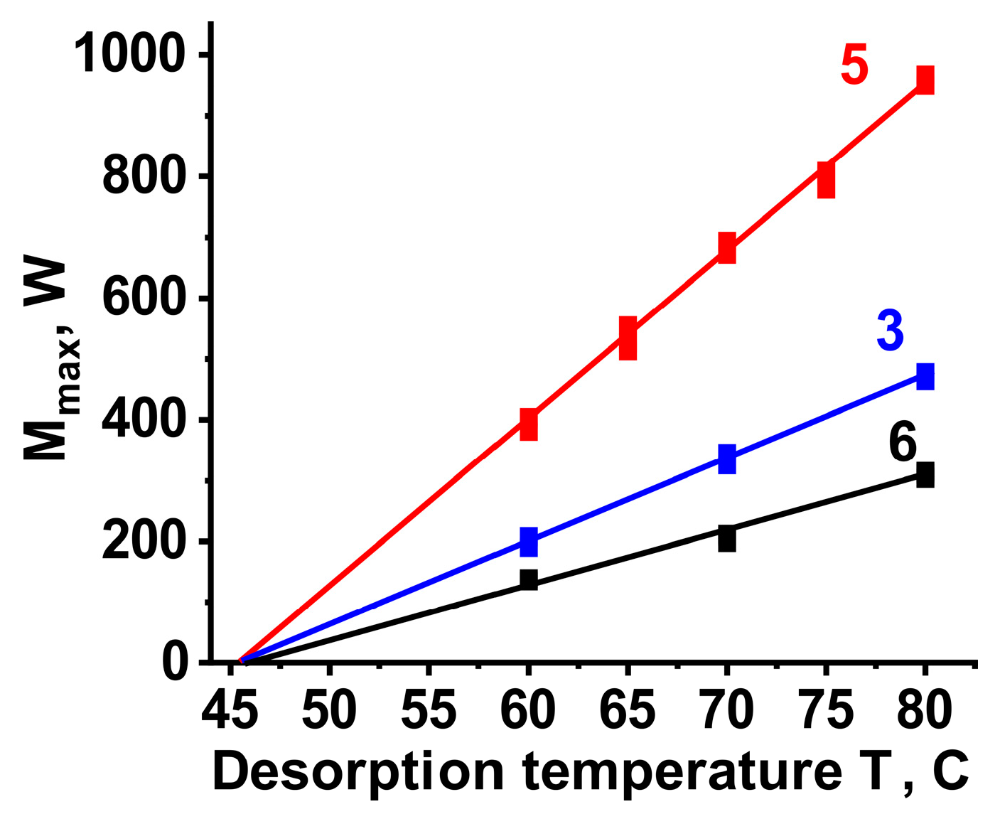
Figure 1. Adsorption heat storage cycle.
Fluids 08 00228 g001
Figure 2. The FFT heat exchanger’s elements and geometry.
Fluids 08 00228 g002
Figure 3. The sorption isobar for LiCl/SiO2–methanol system at evaporator pressure Pcon = 96 mbar corresponding to Tcon = 15 °C calculated from data presented in [48].
Fluids 08 00228 g003
Figure 4. Scheme of setup for desorption experiments.
Fluids 08 00228 g004
Figure 5. (a) Kinetic curves “Q vs. time” of methanol desorption from LiCl/SiO2 composite at Pcon = 96 mbar and Tdes: 70 °C, (Fluids 08 00228 i001) 75 °C, (Fluids 08 00228 i002), 80 °C (Fluids 08 00228 i003), 85 °C (Fluids 08 00228 i004), red line in the insert—linear approximation of initial part. (b) Maximum power vs. temperature driving force, experiment—symbols, red line—linear approximation.
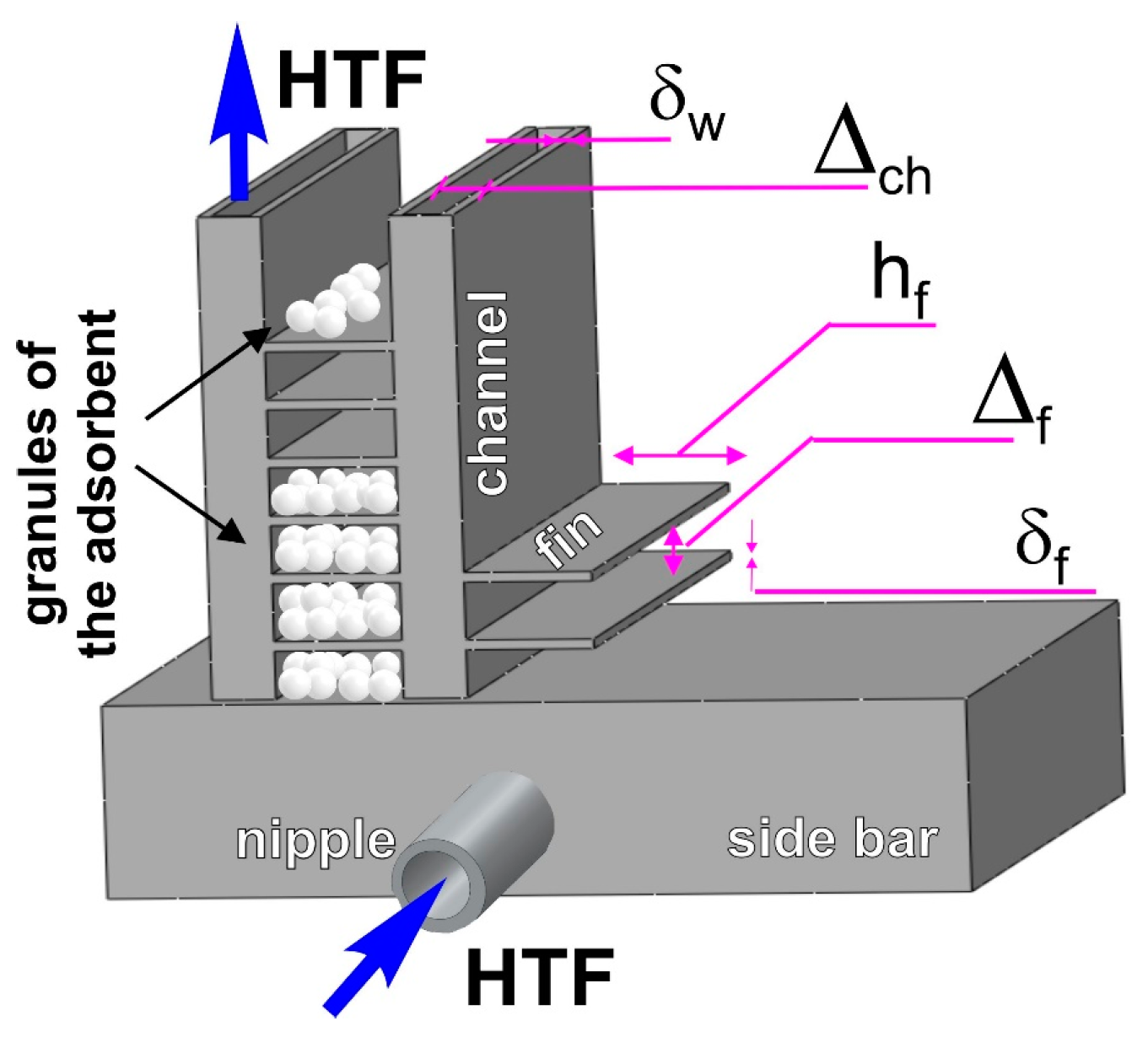
Fluids 08 00228 g005
Figure 6. The theoretically calculated UA coefficients for FFT heat exchangers with different core geometries. The highest UA value (green area), the intermediate UA values (yellow area), the lowest UA values (red area).
Fluids 08 00228 g006
Figure 7. Temperature profiles for desorption, inlet water (red) and outlet water (black) to/from AHex № 5 (a) blank experiment, (b) experiment in the presence of methanol vapors.
Fluids 08 00228 g007
Figure 8. Temperature response of AHex № 5 to the temperature jump at the desorption stage: (a) blank experiment (blue curve), experiment in the presence of methanol vapor (black curve), (b) difference between the previous curves and appropriate power of desorption.
Fluids 08 00228 g008
Figure 9. Dependence of the maximum power on the AHex desorption temperature: № 6 (black), № 3 (blue), № 5 (red). Symbols are experimental data, lines are approximations.
Fluids 08 00228 g009
Table 1. Characteristics considered for cores of FFT radiators.
δwall, µmH’ch, mmHf, mmΔf, mmδf, µm
14872.37.01.887
23571.89.81.488
35042.28.01.575
44181.34.80.952
54170.54.10.948
69322.113.71.8103
75460.86.20.863
85201.05.81.078
Table 2. Characteristics of the desorption process for different AHexes under the conditions of a daily heat storage cycle (temperature jump 41 °C → 80 °C, P(CH3OH) = 96 mbar, f = 202 L/h).
AHexMmax, Wτ0.9, sGdes, kJUAtheor, W/KUAexp, W/K
631022731 ± 38.19 ± 1
347012030 ± 314.914 ± 1
59606032 ± 326.528 ± 2
Disclaimer/Publisher’s Note: The statements, opinions and data contained in all publications are solely those of the individual author(s) and contributor(s) and not of MDPI and/or the editor(s). MDPI and/or the editor(s) disclaim responsibility for any injury to people or property resulting from any ideas, methods, instructions or products referred to in the content.

