Secure Boot for Reconfigurable Architectures


Department of Electrical and Computer Engineering, University of North Carolina at Charlotte, Charlotte, NC 28223, USA
*
Author to whom correspondence should be addressed.
Cryptography 2020, 4(4), 26; https://0-doi-org.brum.beds.ac.uk/10.3390/cryptography4040026
Submission received: 26 August 2020
/
Revised: 21 September 2020
/
Accepted: 23 September 2020
/
Published: 25 September 2020
(This article belongs to the Special Issue Feature Papers in Hardware Security)
Abstract
:Reconfigurable computing is becoming ubiquitous in the form of consumer-based Internet of Things (IoT) devices. Reconfigurable computing architectures have found their place in safety-critical infrastructures such as the automotive industry. As the target architecture evolves, it also needs to be updated remotely on the target platform. This process is susceptible to remote hijacking, where the attacker can maliciously update the reconfigurable hardware target with tainted hardware configuration. This paper proposes an architecture of establishing Root of Trust at the hardware level using cryptographic co-processors and Trusted Platform Modules (TPMs) and enable over the air updates. The proposed framework implements a secure boot protocol on Xilinx based FPGAs. The project demonstrates the configuration of the bitstream, boot process integration with TPM and secure over-the-air updates for the hardware reconfiguration.
1. Introduction
Internet of Things (IoT) are ubiquitous devices with limited functionality and computational resources, enabled with networking features and connectivity to the Internet. These devices have a longer life cycle, where the updates/changes are deployed through software or firmware updates. Software updates can be provided either manually or physically by using cables and programmer interfaces. Physical access to a device for firmware upgrade is always not possible and requires the configuration of the devices in the field through secure channels. The connected nature of IoTs makes them accessible remotely, and firmware updates for devices can be provided using Over the Air (OTA) firmware updates [1,2].
Software firmware updates change the functionality of the software; however, the scope is limited by the hardware capabilities and its architecture. Depending on the application and the expected life of a product, reconfigurable hardware architectures can improve the device updates and secure boot processes. Reconfigurability allows the manufacturer to update the hardware design while the machine is in the field. Using OTA, hardware updates allow for updating the device hardware configuration without the need for physically replacing it.
Over the air (OTA) updates are critical in the embedded system consumer domain such as the cellular phone and automotive industries. The requirements for availability and quality of service are high in safety-critical applications. For the vehicular domain, the requirement for availability is directly tied to safety. Furthermore, it is not feasible for a car owner to take the car to a service station whenever there is a software update available. Instead, firmware updates can be provided remotely with OTA updates that can be transferred via the cellular network directly by the manufacturer [3].
Root of Trust is an anchor for implementing trust in a device [4]. Maintaining Root of Trust (RoT) is crucial once a device has been deployed in an untrusted field. Tainted firmware updates can break the trust. The software domain employs various techniques for maintaining Root of Trust. Some popular examples include Universal Extensible Firmware Interface (UEFI) secure boot extensions [5] and Microsoft Windows’ Secure Boot [6]. The former maintains Root of Trust at the boot level and the latter extends it to the operating system (OS) level. We discuss a novel scheme for implementing Root of Trust using cryptographic processors, such as Trust Platform Modules (TPM).
Reconfigurable hardware has become pervasive in the Internet of Things domain, this is a requirement for extending the Root of Trust to the hardware. Current commercial FPGA vendors provide limited security to the programmable logic fabric and those security mechanisms are limited in application, as shown in Section 2. Additionally, the provided methods have closed access which the users can use in their systems but cannot inspect themselves. There is a need for an open and reliable security structure for the programmable fabric that can be integrated into the device’s Root of Trust.
In this work, we present a framework to establish the Root of Trust for secure boot and OTA updates for reconfigurable hardware. Mutual trust is established between an FPGA device and the server or the content provider. A symmetric encryption key update mechanism is proposed to enable key provisioning for updates. The key update mechanism is tied to the integrity of the bitstream. If there is an unintended change in the integrity of the bitstream, the device will no longer able to successfully decrypt continuing updates from the server. The proposed scheme extends the integration of TPM with the FPGA boot process to assist in secure boot, key provisioning and secure communication. Additionally, we present schemes for runtime mitigation of malicious logic insertion. To the best of the authors’ knowledge, this is the first work that practically provides the integration between TPMs and FPGAs at the First Stage Boot Loader stage. The organization of the paper is as follows. Section 2 discusses the relevant background studies. Section 3 covers the proposed architecture and analysis of the methodologies. Section 4 describes the implementation details and security analysis is discussed in Section 5.
2. Background Studies
2.1. Secure Boot in FPGAs
The security features in FPGAs target various aspects of security, such as secure boot, encryption, data integrity and secure communication. Commercial FPGA vendors have increasingly incorporated new security features over the years, but they do not follow any standard and are not consistent across the devices. In Zynq 7000 FPGAs, the FPGA SoC provides an AES 256 based encryption engine. Additionally, RSA asymmetric authentication is used to ensure an authenticated source. These functions are implemented as a hardware-based function on the FPGA fabric and their configuration is integrated in the EDA tools. The implementation of this core is not open to the end-user [7]. Both the encryption and authentication processes use keys which are defined before deployment. In the Zynq 7000 architecture, there are two ways of key storage: Battery-Backed RAM (BBRAM) and one-time programmable fuses. BBRAM is an on-chip volatile memory region that has to be battery powered. One-time programmable efuses are configurable fuses that are burned into the fabric once they are programmed. There are caveats of using these technologies for holding keys. The BBRAM is dependent on the presence of a dependable power source. In the case there is any fluctuation in the power supply, the keys will be lost. On the other hand, the efuses are once programmable. In the case the programmed keys leak, there is no way to refresh them. Another serious flaw is that these keys are stored unencrypted in the memory. Access can be gained to them through physical means [8] and through side channel attacks [9].
These cryptographic processes are invoked as part of the secure boot process implemented in the Xilinx provided zeroth stage boot loader called BootROM [10]. BootROM code exists in non-volatile memory on the FPGA fabric. It is executed by the Processing System on FPGA at the beginning of the boot cycle. Once the execution is completed by the BootROM code, control is passed to user-defined code, which can be an operating system or a user level application. The vendor provides no access to the code implementation of BootROM and there is neither any read nor write access to the memory holding the BootROM code.
Recently, in the newer Zynq UltraScale architecture, Xilinx has built upon the schemes in the Zynq 7000 architecture to add more security solutions [11,12]. The major revision is in the addition of Physical Unclonable Function (PUF) based key support. Whenever keys are generated for encrypting bitstreams, they are given as input to the on-board PUF to generate an encrypted key. This key can be stored onto the efuses, the BBRAM or externally in any unencrypted space. Since an attacker does not have access to the PUF implementation, they will not be able to decrypt the encryption key. Once the host system sends an encrypted bitstream to the FPGA board, the encrypted key is decrypted at runtime to reveal the bitstream decryption key. This key is used by the encryption subsystem to decrypt the bitstream. Additionally, there are existing commercial platforms that integrate TPM with the FPGA [13], but the security provided is limited to the OS and application layer and does not extend to securing the bitstream.
Attacks on vendor-provisioned security, such as Xilinx’s Secure Boot, have also been documented. Outsourced trusted third-party IPs based on their application also have access to the main memory of the system. Since the main memory is also used by secure boot to store the unencrypted Second Stage Boot Loader (e.g., U-boot) used by the system, a hardware trojan can target the main memory to manipulate the Second Stage Boot Loader to execute a malicious executable. The authors of [14] suggested wrapper logic be added to IPs before the IP is connected to the system bus. Hardcoded configuration of the wrapper defines the scope of memory access by the connecting IP.
Xilinx FPGA bitstreams consist of a sequence of commands that are sent to the FPGA’s Internal Configuration Access Port (ICAP) interface [15]. The ICAP interface is used to interact with the Programmable Logic fabric. There are several registers that an ICAP register provides. The bitstream header instructs if the bitstream is encrypted or not. This sets the FPGA to decrypt the bitstream data using AES-CBC mode. In [16], the authors exploited CBC malleability to alter the bitstream. The malicious modification routes the decrypted bitstream configuration to be written to the fabric, to an alternative ICAP register. The leaked configuration is then collected to retrieve the entire confidential bitstream configuration. Recent work on the secure bitstream configuration at the boot level proposes the use of PUF technology and on-board peripherals for FPGA bitstream secure boot [17]. The ICAP is used to retrieve the configuration of the current programmable logic. A Hardware-Embedded Delay Physical Unclonable Function (HELPUF) [18] uses SHA3 digest as the challenge input. The generated output is used as a key for decrypting the image of the operating system and the application software to realize self-authentication. This enables the second stage boot loader to program the programmable logic PL and processing system PS. Since vendor-provided secure boot is not used with this system, ICAP also allows readback of on-chip memory elements such as the block RAM and registers. If an adversary can capture the readback process, they will also be able to read the PUF output as well and therefore will have access to decryption keys. Another scheme implements self-authentication of the logic fabric design and extends the protection to include processor design [19]. As opposed to the work in [17], this work employs the use of Elliptic Curve Cryptography based asymmetric keys with Diffie–Helman key exchange for the key generation for encryption. A fuzzy key extractor is used to use extract hardware-based variations and to generate a key. This extracted key is used in the design by various cryptographic functions such as remote attestation and encryption key generation.
Dynamic Partial Reconfiguration (DPR) allows reconfiguration of pre-defined sections of the FPGA fabric during runtime. Static design reconfiguration requires the FPGA to be shut down before it can be reprogrammed. Following current security standards followed by FPGA manufacturers [7,20], the static encryption key must also be shared with the third party. Thus, adding more actors who would have access to the key. In [21], the authors suggested improving on the situation, with the involvement of the hardware vendor in the distribution process. Each end device has a Unique ID. This ID is exchanged with the IP provider during an IP purchase transaction. The IP provider passes the unencrypted IP bitstream and the obtained ID of the end device to the vendor. The vendor has a database of IDs of end devices and their corresponding encryption keys. The vendor encrypts the bitstream using the end device’s stored encryption key before it is transmitted to the device. The solution does limit the issue of distribution of the encryption key between parties, however, promotes the use of static symmetric encryption keys.
DPR-based approaches (e.g., [22,23]) suggest dividing the Programmable Logic (PL) fabric into two zones, the static/security partition and the application partition. The security partition implements functions required for authentication of the device, e.g., a PUF. It also supports cryptographic functions such as SHA or AES. The application partition houses the application bitstream. The shortcoming is the area overhead for application logic, which adds a constraint over the application logic design. Additionally, since the security function lies with the application partition in the same fabric at the same time, it thus creates a possibility for secret leakage between the two partitions.
2.2. Trusted Platform Modules
Trusted Platform Modules (TPMs) are hardware-based cryptographic processors. These processors provide hardware-assisted capabilities for secure encryption, signing and digital certificates processes and its storage on tamper-resistant Non-Volatile Memory (NVM). The TPM follows Trusted Computing Group’s (TCG) TPM Profile Specification [24]. TPM provides constructs for key generation, true random number generators, hash and a set of registers known as Platform Configuration Registers (PCR). In TPM 2.0, there are two sets of PCRs, SHA1 and SHA256. PCRs are special registers used to hold hash values for a block of input data and are commonly used in Secure Boot applications. The hash is computed using the TPM’s TPM2_PCR_EXTEND function, for a block size of 256 bits. Each time the hash is computed, it is added to the previous value of a PCR value register.
PCRn = PCRn||SHA256(x)
In Equation (1), n is the PCR number and x is the 256-bit input value. In the secure boot process, computed PCR values are compared with reference values at different times points for verification. Hash functions are one-way functions used for integrity checking [25]. PCR registers commute the cumulative hash, with any bit flip in the configuration will result in an incorrect response. Other capabilities of TPM include support of symmetric and asymmetric cryptographic cores to enable confidentiality and availability.
There are two specification versions, namely 1.2 and 2.0. TPM 2.0 supports several cryptographic cores that are not available in the predecessor version 1.2. A complete list of supported cryptographic engines and the comparison between the two is given in Table 1.
3. Threat Model for Secure Boot of FPGA Bitstreams
The FPGA market is dominated by proprietary tools, Intellectual Properties (IPs) and closed hardware implementation. There are a handful of vendors that provide varying architectures and interfaces to those architectures. The reconfigurable fabric on FPGAs is programmed using bitstreams. The bitstream configures the Look Up Tables (LUTs) in the logic fabric. These LUTs act as combinatorial logic and sequential data paths for the hardware design. Bitstreams also configure other fabric elements, e.g., on-chip memory, Digital Signal Processing (DSP), clocking blocks and wire connections. An attack on the bitstream can affect the entire system operation of a device on the field. This work focuses its efforts on providing bitstream security on the device and on providing security between a content provider and a device.
3.1. Bitstream Spoofing
Bitstream spoofing updates the victim device with an update that seem to come from an authorized source. Bitstream spoofing may compromise the security of the victim device using relay and replay attacks [26,27]. An adversary acts as a man in the middle between a bitstream content provider and a device. Once an authenticated session is set up between the two nodes, the adversary replaces the original bitstream with a malicious one. In the case where the victim device is using one single key for bitstream encryption, replay attacks can be used by an adversary. An attacker can forward an older copy of the bitstream which has limited functionality compared to the current version.
3.2. Runtime Malicious Modification
Once a bitstream has been programmed onto an FPGA programmable logic fabric, an FPGA device may provide interfaces to the outside world for readback and modification of the running bitstream [28]. Using these interfaces, faults or trojans can be introduced in the design [29]. Additionally, the same interfaces can be used to make unauthorized modifications to the original design. Our work focuses on mitigating malicious logic insertion in the bitstream during runtime.
3.3. Nonsecure Communication with Content Provider
For an FPGA device placed in the field, bitstream updates can be provided manually physically by an engineer, through a physical update mechanism or using remote updates over a network. If a content provider over a network is not secure, an adversary may spoof its identity to become a content provider. Therefore, an adversary may be able to push malicious updates to the client. On the other hand, an adversary can also impersonate a device on the field to download bitstream updates from a content provider not meant for it.
4. The Root of Trust Architecture
In the proposed scheme, there are two actors: the content provider or the server and client nodes. The content provider is a server that exists over a network for all client nodes. It serves the latest bitstream to all clients. A client node is any authorized FPGA device that is connected to the network of nodes. The authentication and authorization privileges for a client to join the network is open to the implementation and is left at the discretion of the designer. There are two components in this framework: the proposed hardware and the Secure First Stage Boot Loader (SFSBL).
4.1. Hardware Overview
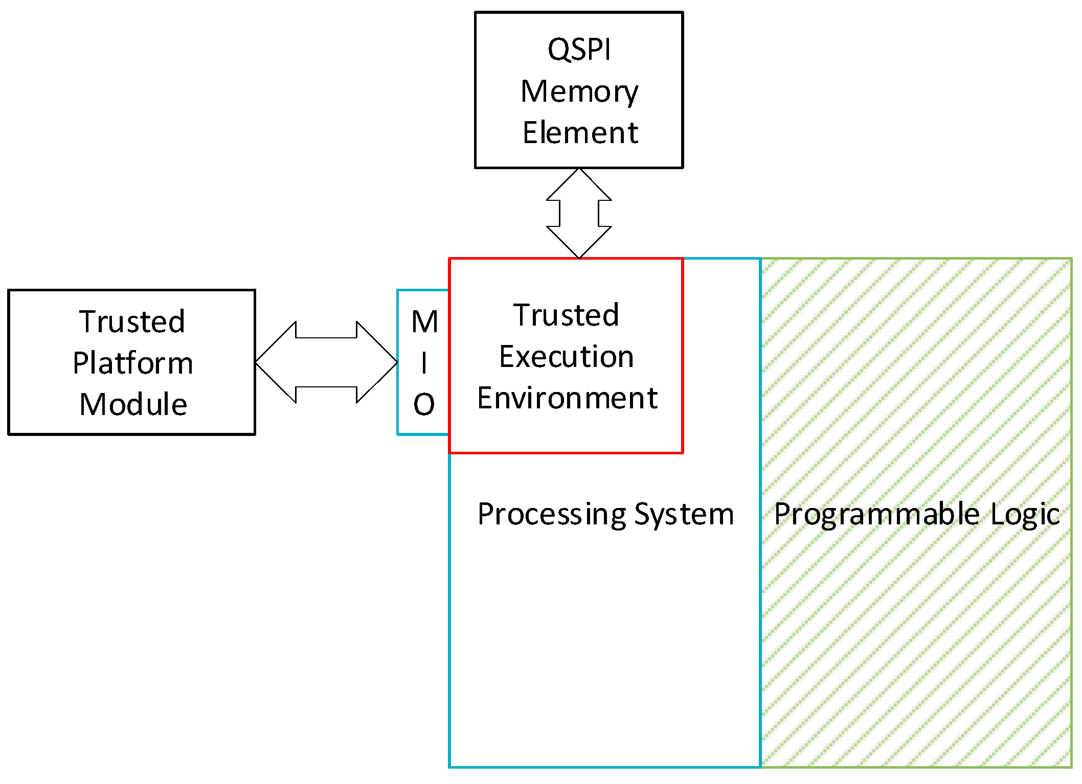
The reference reconfigurable platform is an SRAM based FPGA SoC that has a hard-core Processing System (PS) and a Programmable Logic (PL) fabric. The PS is a trusted verifier and the PL design is the prover. The verifier is a trusted source, whereas the prover needs to prove its legitimacy to the verifier. We investigate the secure co-processor integration with the SoC and export the security functions and key provisioning onto an external cryptographic processor, such as the TPM. To provide isolation for a higher level of security functions that is for Secure OTA update functions, the framework uses a Trusted Execution Environment (TEE), such as ARM’s TrustZone. TPM is interfaced using the Multiplexed Input /Output (MIO) port of the FPGA via serial SPI interface on Xilinx Zynq 7000 series FPGA. An MIO port is directly connected to the hard core of the PS and does not require any additional routing from the PL. The MIO-based connection to the TPM is essential since, in the case PL-based configuration is used, the PL will need to be programmed first, thus introducing a possible attack vector for the target platform. To mitigate any damage caused due to privilege escalation attacks, PL programming port and the TPM are configured to be accessible only through TrustZone’s secure world. The prototype is tested on the Xilinx platform that incorporates external Quad Serial Peripheral Interface (QSPI)-based flash memory to hold the SFSBL and the bitstream. The write access to the flash memory is limited to the flash memory and is also limited to TrustZone configured secure world. The hardware is described in Figure 1.
4.2. Establishing Source of Trust
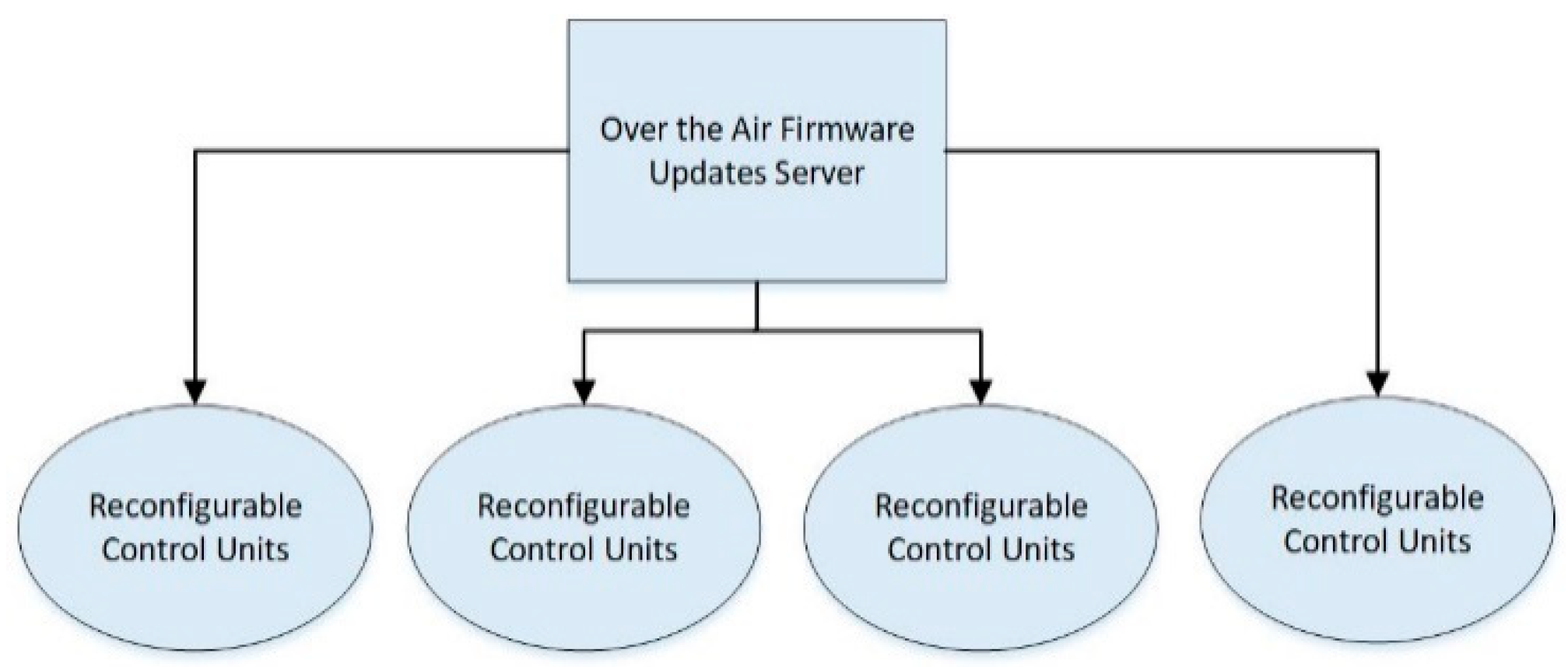
A content provider/server may serve multiple client nodes, as illustrated in Figure 2. The server is assumed to be secure. To establish the identity of the content provider and a client node, asymmetric digital keys are used. The proposed framework uses Elliptic Curve Digital Signature Algorithm-based NISTP256 curve keys [30] for data signing. A pair of asymmetric signing keys are generated on the server as well as each client node. The client nodes use the equipped TPM to generate the key pairs. Additionally, a unique shared symmetric key is generated for each client. This key acts as a base encryption key (Kb) and is updated during the bitstream update process. The update process of the symmetric encryption key is discussed in detail in the following subsections. A client’s private key (Kcpr), public key (Kcpb), the server’s public key (Kps) and the encryption key are stored on a client’s TPM, in its NVM. The exchange of keys occurs in a trusted environment, where the server’s private key (Krs) does not leave the system. The server maintains a database of all its client’s public keys and the base encryption keys. This system supports key renewal; however, the lifetime of the keys is left at the discretion of the system designer. To mitigate chances for key theft, it is assumed that the renewal process occurs in a trusted environment. Once deployed, the private key of the client cannot be retrieved from the TPM; however, it can be addressed for use within the TPM. The key exchange process is illustrated in Figure 3.
Bitstreams are stored in the QSPI Flash on the hardware. The initial bitstream is stored by the vendor in the trusted field. The proposed framework uses Platform Configuration Registers (PCR) to measure the boot process and to maintain prolonged integrity of the bitstream. PCR register, PCRt is used to store the cumulative SHA256 of all the bitstreams loaded onto the client. Initially, the value of PCRt is set to the SHA256 of the initial bitstream. The server also calculates the same cumulative hash locally (SHAt). For use during secure boot at the client, the SHA256 of the bitstream (SHAc) is stored on the NVM in the TPM. Figure 4 shows the keys on a client node and shared between a server.
4.3. Secure Over the Air (OTA) Update Mechanism
When the updated bitstream available on the server, the connected and authorized client nodes receive a notification from the server. This triggers a client to initiate secure communication with the server. At a client, the mode of operation switches from normal mode to the update mode. The update mode is handled by the trusted execution environment at the client. In the case of TrustZone, the processor mode switches from the non-secure world to the secure world. The update process is assigned its own memory area, isolated from the non-secure world. The update procedure consists of the following processes.
4.3.1. Secure Communication Handshaking
To enable secure communication between the server and the client and maintain the integrity of the bitstreams between two subsequent updates, we propose a handshaking scheme. The scheme is summarized in Figure 5. A client generates a True Random Number (TRNa) using the True Random Number Generator equipped on the TPM. The PCR register value PCRt is XORed with TRNa and is then symmetrically encrypted using the base encryption key Kb.
me = AES128(PCRt ^ TRNa) Kb
The construction of the encrypted message (me) is shown in Equation (2). Hash of me is asymmetrically signed using Kcpr. Message me and its hash is sent to the server. After transmission, the Kb is updated client side by taking a XOR with TRNa. Kb on the TPM is also replaced with the newly computed value. Equation (3) illustrates the update process.
Kb = Kb ^ TRNa
The server using its copy of Kcpb recalculates the hash of the received message me. Once the client has been authenticated, the server decrypts me using the stored key Kb. To retrieve TRNa, the server computes the XOR of SHAt with the decrypted message. As in the client node, Kb is updated at the server.
4.3.2. Secure Update Packaging and Transfer
The bitstream update is compiled into an archive package before it is sent to a client. Using the bitstream update and SHAt, the server calculates the new cumulative hash and updates SHAt. The updated bitstream and SHAt are combined and encrypted using the updated key Kb. This encrypted block is copied to the update archive package along with its SHA256 value. The SHA256 value is signed using its own private key Krs. The signature is appended to the package. The update archive is sent to the client. The client stores the package in its NVM and triggers the update process. Figure 6 shows the archive package.
4.3.3. Applying the Update
The process of applying the update on the target platform is handled by the secure update process running on the client FPGA. Once the bitstream package has been downloaded, SHA256 of the package is recalculated client side and is compared with that in the download package. The signature of the computed hash is recomputed using the key Kps on the TPM. This signature is compared against the signature packaged in the update archive. Once the identity of the server has been verified, the encrypted archive is decrypted using Kb. Using the TPM PCR functions, PCRt is updated and verified against the archived SHAt value. If the updated PCRt and SHAt values are equal, the initial bitstream on the NVM is replaced by the update; otherwise, if in case any check fails during the update process, the node is assumed to be compromised and the server is notified. On completion of the update process, the individual SHA256 of the bitstream calculated and SHAc is updated. The process is described in the flowchart in Figure 7.
4.3.4. Secure FSBL Boot Process
We designed a Secure First Stage Boot Loader (SFBSL) that is integrated with the Trusted Platform Module with custom device drivers that enable the device to communicate with the TPM before the device has booted. In an FPGA, the zeroth stage boot loader referred to as BootROM is executed by the Processing System on FPGA at the beginning of the boot cycle. BootROM code exists in a non-volatile memory of the FPGA fabric and is assumed to be secure. Once the BootROM has completed its execution, the control is passed to the proposed SFSBL that exists in the on-board QSPI memory. The SFSBL code extends and integrates the security functions to the FSBL. FSBL configures the device with the hardware bitstream and configures the processing system with a bare-metal application or loads the second stage boot loader to the RAM. This, in turn, loads the operating system. The vendor FSBL design does not verify the integrity of the bitstream or what it is programming on the processing system. This lack of security at the boot process can be circumvented with the proposed secure FSBL that integrates key management and security features to validate the configuration files before programming the device.
The proposed SFSBL begins execution with initializing on-board components and memory elements. Once the basic devices have been initialized, the TrustZone is set up. The access to the MIO port connected to the TPM as well as the QSPI ports is both configured to be accessible only by TrustZone’s secure world. The secure world code is copied onto the RAM. This segment of memory is only addressable through secure applications. Once the setup is complete, the control is switched to the secure world. The secure world initiates the process of secure FPGA boot. To mitigate exploitation of Time of Check Time of Use (ToCToU) [31] by an attacker, the processing system recomputes the cumulative SHA256 of the bitstream on the TPM. This value is compared with SHAc stored on the TPM during the bitstream update process. If the values are different, the boot process stalls, and the violation is recorded for later reference. Otherwise, the bitstream is configured onto the FPGA programmable logic fabric and the boot process continues.
The secure world sets up service hooks for the non-secure world. These hooks can be used to provide security functions for applications. One such service is the bitstream update service, in which the control is switched to the secure world. The SFSBL process continues with loading the non-secure world application, which can be either a bare-metal application or a second stage boot loader, e.g., U-Boot [32]. The SFSBL process finishes by switching back to the non-secure world and passing the control of execution to the non-secure world.
5. Results and Analysis
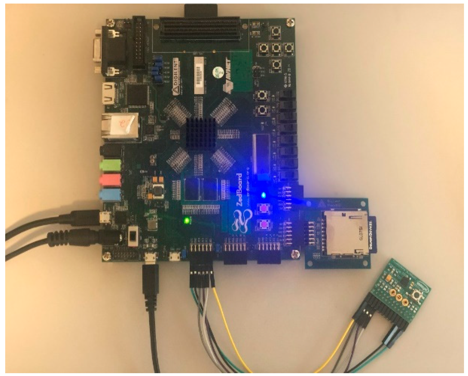
The proposed framework was implemented on a Xilinx Zedboard FPGA board equipped with a Zynq-7000 XC7Z020-CLG484 [33]. The FPGA has an embedded ARM Cortex A9 hard processor. The FPGA is integrated with the Infineon TPM SLB9670, a secure coprocessor for the key management and secure boot processes [34]. The processor is equipped with ARM’s TrustZone for Trusted Execution Environment (TEE). Additionally, the on-board QSPI memory is used for holding the SFSBL implementation and the bitstream package extracted from the bitstream update process. The experimental setup of the proposed framework is shown in Figure 8.
The FPGA board communicates with the TPM via the Serial Peripheral Interface (SPI) over the dedicated MIO port. The proposed SFSBL implementation is the extension of the Xilinx provided First Stage Boot Loader (FSBL). The secure extensions are added to the existing FSBL that uses the custom device driver library written as part of this research.
The MIO ports are accessible through the secure world configured using ARM processor TrustZone [35]. The total RAM on the Xilinx Zedboard is 512 MB. We configured upper 64 MB of the RAM space to be used by the secure world. This setting is controlled using the TZ_DDR_RAM register. Additionally, to limit access to the QSPI memory, the QSPI_S_APB bit in the SECURITY6_APB_SLAVES register is set to 0. Typically, for the configuration of peripherals in TrustZone, the value “0” signifies that a peripheral is set to be secure or only accessible from the secure world.
To incorporate the TPM with the FPGA board at the FSBL level, we implemented a device driver library. This library provides all necessary functions to set up the TPM and implements security functions on the TPM. To the best knowledge of the authors, this is the first library of its kind. The SPI interface accessible through the secure world implements the TPM transfer function driver to communicate with the TPM device. This communication is required at the FSBL level to perform secure boot, which is not supported until the second stage boot loader in the traditional design flow.
The device driver library is open source and is made available online for public use [36]. The services provided by the library can be divided into two categories: device power-up services and cryptographic functions. TPM 2.0 architecture has five layers. These layers signify the boot stage for a target platform and are termed as localities. Each locality offers specific functionalities and implements privileges with restrictions of allowed functions, for example, the PCR registers are resources limited to specific localities. Our library implementation provides access to different secure boot specific functions at all localities. In the proposed framework implementation, the TPM is only accessible from the trusted secure world: the library exists in the scope of the secure world and is not accessible from the non-secure world.
Timing overhead for the proposed solution is dependent on the data rate of the SPI interface and the wait time for each operation. The data rate of the SPI interface is dependent on the host and the TPM device. The TPM2 specifications only specify a maximum timeout for a message transfer and timeout for primitive operations such as requesting a locality, checking the ownership of a locality, etc.
For each request sent to the TPM, the TPM can notify the host that it is busy using a wait state. The TPM can send a maximum of 100 wait states before a timeout can occur. In the case of a timeout, the host must send its request again.
Pseudocode of the TPM extend function driver implementation is given in Algorithm 1. The TPM extend computes the hash of the input stream in a sequence of fixed size blocks of 32 bytes. It enables block-by-block hash computation, which is the performance bottleneck for the bitstream processing. Algorithm 2 shows the optimized hash computation process, that supports data streaming with the block size 64 bytes. For the secure boot operation, the TPM structure TPM2_PCR_EXTEND reads data in chunks of 32 bytes to extend a PCR. The bitstream for the Xilinx Zedboard is 3.85 MB in size. Each TPM2_PCR_EXTEND operation takes an input of 32 bytes, and it takes a total of 126k hashing operations.
| Algorithm 1: tpm_pcr_extend function |
| Inputs: Locality (L), PCR Index I, Data Input D |
| Output: PCR Based Hash (H) |
| Buffer = [] If (!Current active locality is L) then Request locality L from TPM If (!Current active locality is L) then Raise Exception //Make TPM2_PCR_EXTEND Request Buffer += TPM2_PCR2_EXTEND Header with Locality (L), PCR Index(I) Buffer += DATA_LENGTH (32) Buffer += D Send Buffer to TPM H = TPM2_PCR_READ(PCR=I) Return H |
| Algorithm 2: ComputeHashLoc4 Function |
| Inputs: Data Block (D), |
| Output: Hash H |
| If (!Current active locality is 4) then Request locality 4 from TPM If (!Current active locality is 4) then Raise Exception Send TPM_HASH_START Request to TPM For (I: each block of length 64 in D) If length(I) <64 then I += Padding Send TPM_HASH_DATA + I to TPM Send TPM_HASH_END Request to TPM H = TPM_READ_PCR(PCR=17) Return H |
To reduce the timing overhead for computing cumulative hash in real world applications, TPM 2.0 provides a separate locality, locality 4. It allows calling the three structures TPM_HASH_START, TPM_HASH_DATA and TPM_HASH_END. To compute the cumulative hash of the bitstream, firstly, the TPM_HASH_START structure is issued. It dictates the TPM to become ready to receive streaming data. Using the TPM_HASH_DATA structure, SFSBL streams the bitstream over to the TPM iteratively. Once the transfer is complete, the TPM_HASH_END structure is sent to denote the end of the data input. The computation time was observed to be 40 s for the target bitstream file of size 3.85 MB. Algorithm 2 shows the implementation of the function. In the SFSBL implementation, this function is made part of the image_mover.c file since this file is responsible for copying bitstream images between mediums.
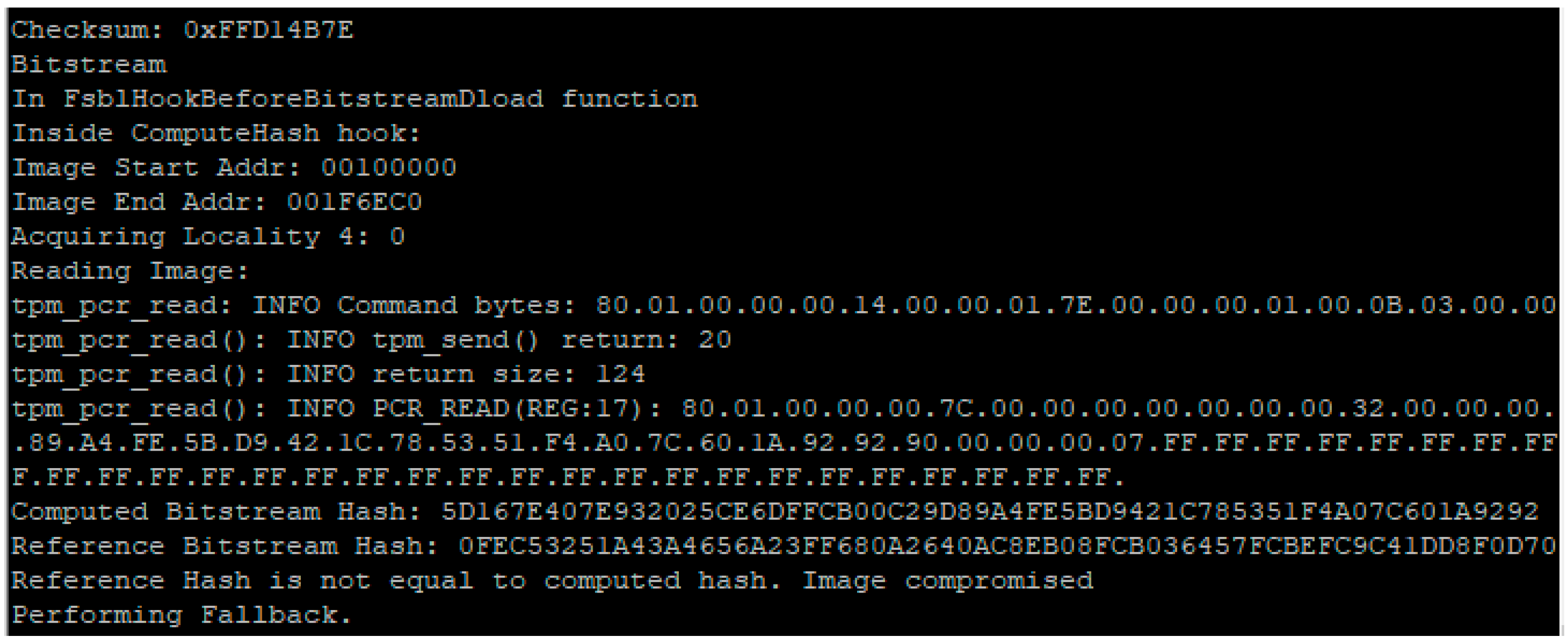
The secure boot process loads the bitstream, as shown in Figure 9. The bitstream is sent to the TPM for the integrity checking, where the cumulative hash is computed using the PCR registers with the scheme discussed in Section 3. The TPM driver loads the PCR register with the cumulative hash for the 3.85 MB bitstream with the 256-bit segments along with the feedback from the PCR cumulative hash. The novel bare-metal TPM driver library uses locality 4 interface to access the PR registers and implements the TPM_PCR_READ structure with the function tpm_pcr_read. The hash value computed by the tpm_pcr_read function call is compared with the golden reference value stored on the temper resistant storage. In Figure 9, the reference hash is not equal to the computed hash, therefore the boot process halts and results in jumping to the fallback process. In the fallback process, the device is only capable of bare-metal functionality with limited networking capabilities to mitigate the impact of the compromised device over the network.
6. Security Analysis
Reconfigurable computing is becoming ubiquitous combined in the IoT devices that embedded devices with long life cycles. The primary goal of SFSBL framework is to enable security features to establish secure boot and TPM based over the air secure hardware configuration updates on the field to enable these devices to evolve and update with the change in device requirements, such as security patches. In this section, we discuss the security properties of the proposed framework.
- Digital certificates are used for the identification of the server and participating nodes. The certificates are shared before deployment by the trusted authority and can only be modified by the trusted facility. Thus, impersonation and data spoofing are not possible in the proposed scheme.
- The encrypted configuration bitstream is packaged with the SHA256 of the encrypted bitstream, along with the bitstream package signature signed off with the private key of the server. Any changes in the bitstream will fail the hash comparison and the device will discard the updates. This prohibits the man in the middle and data spoofing attacks and provides an authentication mechanism for securely transfer the configuration files.
- The keys are stored on the tamper-resistant storage inside TPM on server and device nodes, eliminating invasive and probe attacks to break the key. Furthermore, the private keys never leave the premises, thus mitigates the man in the middle attack.
- The symmetric encryption key is updated on every bitstream. It ensures freshness of encryption keys as well as mitigates replay attacks. Once the key is used, it is never used again and hence any repeated keys can be used to identify attacks.
- During the execution, the device cannot be altered, and the keys can be accessed with the hardware isolation protection of the SPI interface. The TPM interface is only accessed in the secure mode.
7. Conclusions
In this paper, the security extensions of reconfigurable logic-based embedded device are proposed to enable secure boot processes and the firmware updates to reconfigure the hardware and software to run on the device in an untrusted field. We have integrated the TPM capabilities at the boot level with the custom drivers that are integrated at the first stage boot loader to verify the bitstream before the programmable logic is configured or the software is loaded to identify any malicious modifications in the device configuration files. The framework integrates the existing security features such as the trusted execution environment and enables the trusted platform module capabilities with the custom drivers that interface with the FSBL to implement secure boot process. We demonstrate the secure boot and authentication processes for the over the air updates to the firmware in the field.
Author Contributions
Conceptualization, A.S.S. and F.S.; Methodology, A.S.S.; Software, A.S.S.; Validation, A.S.S., Y.G. and F.S.S.; Formal analysis, A.S.S. and F.S.; Investigation, A.S.S.; Resources, A.S.S. and F.S.; Writing—original draft preparation, A.S.S.; Writing—review and editing, F.S. and Y.G.; Visualization, A.S.S.; Supervision, F.S.; All authors have read and agreed to the published version of the manuscript.
Funding
This research was funded by NSF, grant numbers 1814420, 1819694 and 1819687.
Conflicts of Interest
The authors declare no conflict of interest.
References
- Schmidt, S.; Tausig, M.; Hudler, M.; Simhandl, G. Secure Firmware Update over the Air in the Internet of Things Focusing on Flexibility and Feasibility. 2016. Available online: https://www.researchgate.net/profile/Mathias_Tausig/publication/306252903_Secure_Firmware_Update_Over_the_Air_in_the_Internet_of_Things_Focusing_on_Flexibility_and_Feasibility_Proposal_for_a_Design/links/57b4721408aede8a665a50e2.pdf (accessed on 2 October 2018).
- Chandra, H.; Anggadjaja, E.; Wijaya, P.S.; Gunawan, E. Internet of Things: Over-the-Air (OTA) firmware update in Lightweight mesh network protocol for smart urban development. In Proceedings of the Asia-Pacific Conference on Communications, Yogyakarta, Indonesia, 25–27 August 2016; pp. 115–118. [Google Scholar]
- Andrade, C.E.; Byers, S.D.; Gopalakrishnan, V.; Halepovic, E.; Majmundar, M.; Poole, D.J.; Tran, L.K.; Volinsky, C.T. Managing massive firmware-over-the-air updates for connected cars in cellular networks. In Proceedings of the 2nd ACM International Workshop on Smart, Autonomous, and Connected Vehicular Systems and Services, Co-Located with MobiCom, New York, NY, USA, 16–20 October 2017; pp. 65–72. [Google Scholar]
- Zimmer, V.; Krau, M. Establishing the Root of Trust. 2016. Available online: https://www.uefi.org/sites/default/files/resources/UEFI%20RoT%20white%20paper_Final%208%208%2016%20%28003%29.pdf (accessed on 5 January 2020).
- Wilkins, R.; Richardson, B. Uefi Secure Boot in Modern Computer Security Solutions. 2013. Available online: https://media.kasperskycontenthub.com/wp-content/uploads/sites/63/2014/06/21032725/UEFI_Secure_Boot_in_Modern_Computer_Security_Solutions_2013.pdf (accessed on 4 November 2019).
- Secure the Windows 10 Boot Process|Microsoft Docs. Available online: https://docs.microsoft.com/en-us/windows/security/information-protection/secure-the-windows-10-boot-process (accessed on 4 October 2018).
- Xilinx Inc. Zynq-7000 All Programmable SoC Secure Boot. 2014. Available online: https://www.xilinx.com/support/documentation/user_guides/ug1025-zynq-secure-boot-gsg.pdf (accessed on 11 April 2018).
- Trimberger, S.M.; Moore, J.J. FPGA security: Motivations, features, and applications. Proc. IEEE 2014, 102, 1248–1265. [Google Scholar] [CrossRef]
- Tajik, S.; Lohrke, H.; Seifert, J.P.; Boit, C. On the power of optical contactless Probing: Attacking bitstream encryption of FPGAs. In Proceedings of the ACM Conference on Computer and Communications Security, Dallas, TX, USA, 30 October–3 November 2017; pp. 1661–1674. [Google Scholar]
- Xilinx Inc. TR Manual Zynq-7000 All Programmable SoC; Xilinx: San Jose, CA, USA, 2015; Volume 585, pp. 1–1863. [Google Scholar]
- Xilinx Inc. Zynq UltraScale+ Device Technical Reference Manual UG1085. 2018. Available online: https://www.xilinx.com/content/dam/xilinx/support/documentation/user_guides/ug1085-zynq-ultrascale-trm.pdf (accessed on 20 January 2020).
- Xilinx Inc. Developing Tamper-Resistant Designs with Zynq UltraScale+ Devices. 2018. Available online: https://www.xilinx.com/support/documentation/application_notes/xapp1323-zynq-usp-tamper-resistant-designs.pdf (accessed on 11 April 2018).
- Iveia Atlas-I-Z8 Low-Power Zynq UltraScale+ SoM-iVeia. Available online: http://iveia.com/atlas-i-z8 (accessed on 30 November 2018).
- Jacob, N.; Heyszl, J.; Zankl, A.; Rolfes, C.; Sigl, G. How to break secure boot on FPGA SoCs through malicious hardware. In Cryptographic Hardware and Embedded Systems—CHES 2017; Fischer, W., Homma, N., Eds.; Springer: Cham, Switzerland, 2017; Volume 10529, pp. 425–442. [Google Scholar]
- Xilinx Inc. UG 470-7 Series FPGAs Configuration. Available online: https://www.xilinx.com/support/documentation/user_guides/ug470_7Series_Config.pdf. (accessed on 30 July 2019).
- Ender, M.; Moradi, A.; Paar, C. The Unpatchable Silicon: A Full Break of the Bitstream Encryption of Xilinx 7-Series FPGAs. 2020. Available online: https://www.usenix.org/system/files/sec20-ender.pdf (accessed on 12 January 2020).
- Owen, D., Jr.; Heeger, D.; Chan, C.; Che, W.; Saqib, F.; Areno, M.; Plusquellic, J. An Autonomous, Self-Authenticating, and Self-Contained Secure Boot Process for Field-Programmable Gate Arrays. Cryptography 2018, 2, 15. [Google Scholar] [CrossRef] [Green Version]
- Che, W.; Saqib, F.; Plusquellic, J. PUF-based authentication. In Proceedings of the 2015 IEEE/ACM International Conference on Computer-Aided Design (ICCAD), Austin, TX, USA, 2–6 November 2015; pp. 337–344. [Google Scholar]
- Lebedev, I.; Hogan, K.; Devadas, S. Invited paper: Secure boot and remote attestation in the sanctum processor. In Proceedings of the IEEE Computer Security Foundations Symposium, Oxford, UK, 9–12 July 2018; pp. 46–60. [Google Scholar]
- Xilinx Inc. Using Encryption and Authentication to Secure an UltraScale/UltraScale+ FPGA Bitstream Application Note (XAPP1267). 2017. Available online: https://www.xilinx.com/support/documentation/application_notes/xapp1267-encryp-efuse-program.pdf (accessed on 1 February 2018).
- Carelli, A.; Cristofanini, C.A.; Vallero, A.; Basile, C.; Prinetto, P.; di Carlo, S. Securing bitstream integrity, confidentiality and authenticity in reconfigurable mobile heterogeneous systems. In Proceedings of the 2018 IEEE International Conference on Automation, Quality and Testing, Robotics, Cluj-Napoca, Romania, 24–26 May 2018; pp. 1–6. [Google Scholar]
- Vliegen, J.; Rabbani, M.M.; Conti, M.; Mentens, N. SACHa: Self-Attestation of Configurable Hardware. In Proceedings of the Europe Conference and Exhibition, Florence, Italy, 25–29 March 2019; pp. 746–751. [Google Scholar]
- Pocklassery, G.; Che, W.; Saqib, F.; Areno, M.; Plusquellic, J. Self-authenticating secure boot for FPGAs. In Proceedings of the 2018 IEEE International Symposium on Hardware Oriented Security and Trust (HOST), Washington, DC, USA, 30 April–4 May 2018; pp. 221–226. [Google Scholar]
- Trusted Computing Group. TCG PC Client Platform TPM Profile (PTP) Specification Family ‘2.0′ TCG Public Review. 2017. Available online: https://www.trustedcomputinggroup.org/wp-content/uploads/PCClientPlatform-TPM-Profile-for-TPM-2-0-v1-03-20-161114_public-review.pdf (accessed on 20 July 2018).
- Arthur, W.; Challener, D.; Goldman, K. A Practical Guide to TPM 2.0. 2015. Available online: https://0-link-springer-com.brum.beds.ac.uk/book/10.1007/978-1-4302-6584-9 (accessed on 7 July 2018).
- Drimer, S. Volatile FPGA Design Security—A Survey. 2008. Available online: https://pdfs.semanticscholar.org/c766/73ebed90f741f6804ee301362d9e7b366173.pdf (accessed on 30 January 2019).
- Zhang, J.; Lin, Y.; Qu, G. Reconfigurable Binding against FPGA Replay Attacks. ACM Trans. Des. Autom. Electron. Syst. 2015, 20, 1–20. [Google Scholar]
- Xilinx AXI Hardware ICAP. Available online: https://www.xilinx.com/products/intellectual-property/axi_hwicap.html (accessed on 11 May 2019).
- Chakraborty, R.S.; Saha, I.; Palchaudhuri, A.; Naik, G.K. Hardware trojan insertion by direct modification of FPGA configuration bitstream. IEEE Des. Test. 2013, 30, 45–54. [Google Scholar] [CrossRef]
- NIST. Recommended Elliptic Curves for Federal Government Use. Available online: https://github.com/isislovecruft/library--/blob/master/cryptography%20%26%20mathematics/elliptic%20curve%20cryptography/Recommended%20Elliptic%20Curves%20for%20Federal%20Government%20Use%20(1999)%20-%20NIST.pdf (accessed on 24 September 2020).
- Francillon, A.; Nguyen, Q.; Rasmussen, K.B.; Tsudik, G. A minimalist approach to Remote Attestation. In Proceedings of the Design, Automation & Test, Europe Conference & Exhibition, Dresden, Germany, 24–28 March 2014. [Google Scholar]
- WebHome-U-Boot-DENX. Available online: https://www.denx.de/wiki/U-Boot (accessed on 29 October 2019).
- AVNET ZedBoard|Zedboard. Available online: http://zedboard.org/product/zedboard (accessed on 19 January 2018).
- SLB 9670VQ2.0—Infineon Technologies. Available online: https://www.infineon.com/cms/en/product/security-smart-card-solutions/optiga-embedded-security-solutions/optiga-tpm/slb-9670vq2.0/ (accessed on 3 November 2018).
- Xilinx Inc. Programming ARM TrustZone Architecture on the Xilinx Zynq7000 All Programmable SoC User Guide (UG1019). 2014. Available online: https://www.xilinx.com/support/documentation/user_guides/ug1019-zynq-trustzone.pdf (accessed on 23 July 2019).
- Siddiqui, A.S.; Saqib, F. HEADS-UNCC/TPM_Baremetal_Drivers: TPM Baremetal for FPGAs and other Embedded Systems. Available online: https://github.com/HEADS-UNCC/TPM_baremetal_drivers (accessed on 18 June 2020).
Figure 1.
Proposed System Architecture.

Figure 2.
Content Provider connected with clients in an untrusted field.

Figure 3.
Key exchange in a trusted environment.

Figure 4.
Keys shared between a client and server.
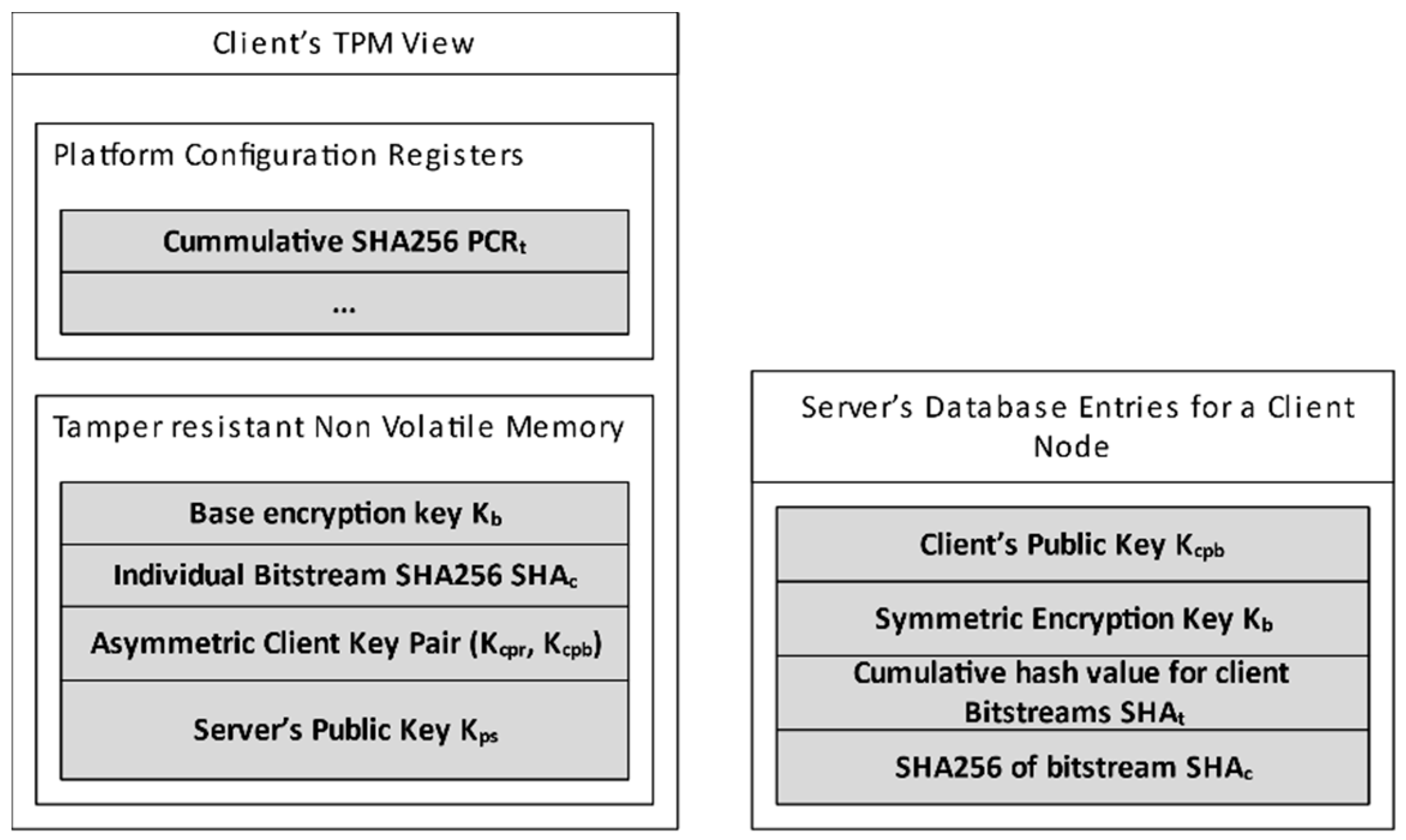
Figure 5.
Server Client Interaction for Bitstream Updates.
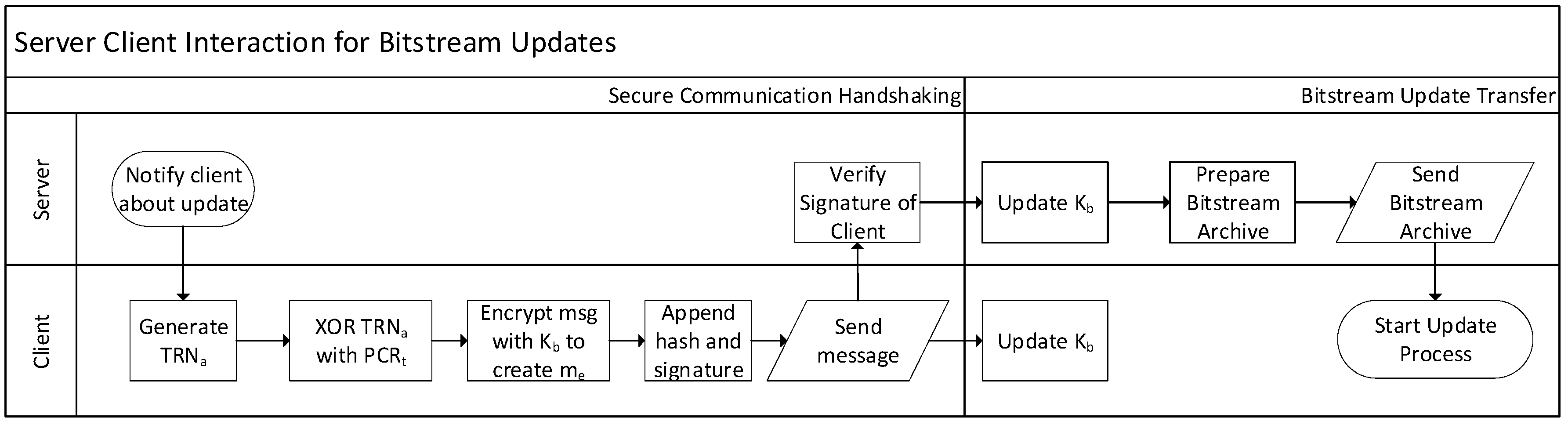
Figure 6.
Bitstream Update Archive.
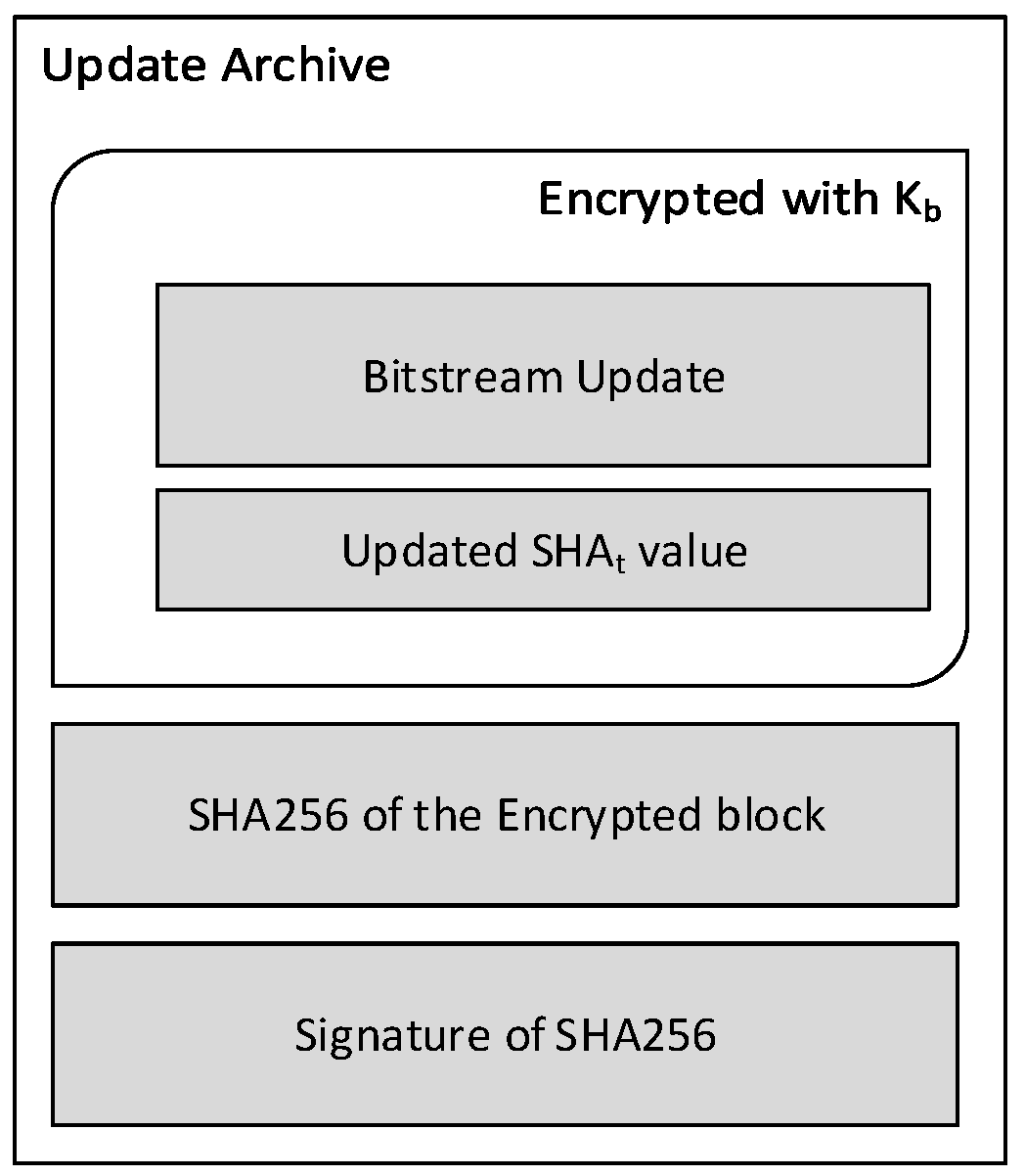
Figure 7.
Secure Bitstream Update Process.
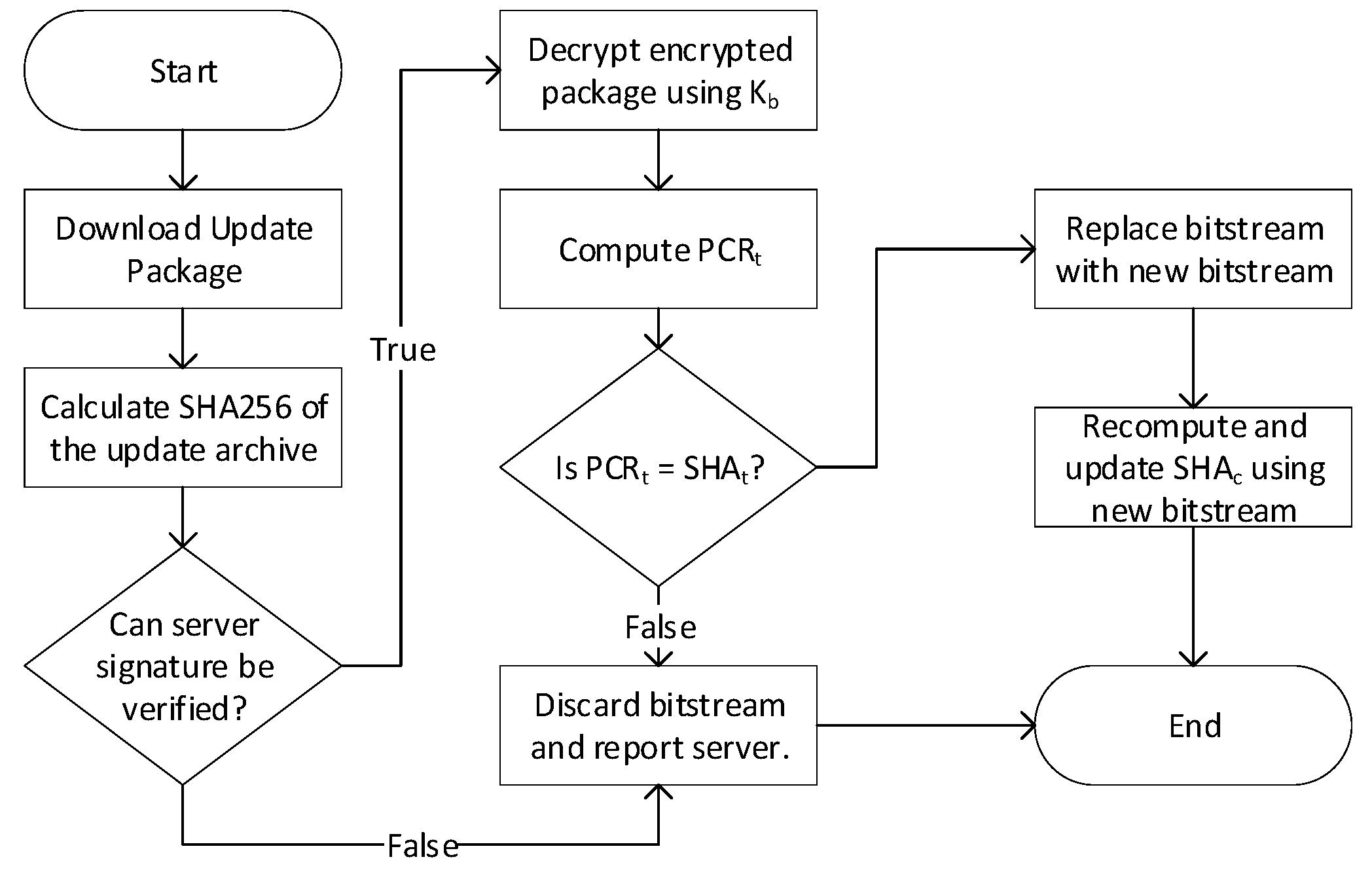
Figure 8.
Experimental setup featuring TPM connected with an FPGA.

Figure 9.
Difference in computed hash and PCR based reference hash found during the boot process.


Table 1.
Comparison between TPM 1.2 and TPM 2.0.
| Algorithm | RSA 1024 | RSA 2048 | ECC NISTP256 | ECC BNP256 | AES 128 | AES 256 | SHA1 | SHA256 |
|---|---|---|---|---|---|---|---|---|
| TPM 1.2 | Yes | Yes | No | No | Optional | Optional | Yes | No |
| TPM 2.0 | Optional | Yes | Yes | Yes | Yes | Optional | Yes | Yes |
© 2020 by the authors. Licensee MDPI, Basel, Switzerland. This article is an open access article distributed under the terms and conditions of the Creative Commons Attribution (CC BY) license (http://creativecommons.org/licenses/by/4.0/).
Share and Cite
MDPI and ACS Style
Siddiqui, A.S.; Gui, Y.; Saqib, F. Secure Boot for Reconfigurable Architectures. Cryptography 2020, 4, 26. https://0-doi-org.brum.beds.ac.uk/10.3390/cryptography4040026
AMA Style
Siddiqui AS, Gui Y, Saqib F. Secure Boot for Reconfigurable Architectures. Cryptography. 2020; 4(4):26. https://0-doi-org.brum.beds.ac.uk/10.3390/cryptography4040026
Chicago/Turabian StyleSiddiqui, Ali Shuja, Yutian Gui, and Fareena Saqib. 2020. "Secure Boot for Reconfigurable Architectures" Cryptography 4, no. 4: 26. https://0-doi-org.brum.beds.ac.uk/10.3390/cryptography4040026