Dual-Input Photovoltaic System Based on Parallel Z-Source Inverters


1
Department of Mechanical and Electrical Engineering, Electrical Engineering Section, University of Southern Denmark, 5230 Odense, Denmark
2
Intelligent Electrical Power Grids at Department of Electrical Sustainable Energy, Delft University of Technology, 5031, 2600 GA Delft, The Netherlands
3
Department of Mechanical and Electrical Engineering, Electrical Engineering Section, University of Southern Denmark, 6400 Sønderborg, Denmark
*
Author to whom correspondence should be addressed.
Designs 2020, 4(4), 51; https://0-doi-org.brum.beds.ac.uk/10.3390/designs4040051
Submission received: 29 September 2020
/
Revised: 25 November 2020
/
Accepted: 26 November 2020
/
Published: 1 December 2020
Abstract
:This paper aims to present a new structure of the parallel Z-source inverters (ZSIs) for dual-input single-phase grid-connected photovoltaic (PV) systems. The ZSI is a single-stage buck-boost converter that uses an inductor-capacitor network between the inverter bridge and the PV string and follows the maximum power point by applying the shoot-through vector. Therefore, a DC/DC converter is no longer needed to track the maximum power point, and the cost and complexity of the power conditioning system (PCS) are reduced. For controlling the proposed PCS, a cascade control structure is employed in this paper. The inner current loop injects the maximum active power with unity power factor sinusoidal current to the grid. The outer capacitor voltage loop is applied to control capacitors voltages in the Z-source networks. Additionally, an enhanced dual-string maximum power point tracking (eDS-MPPT) method is proposed to find MPPs with minimum burden competitional. The eDS-MPPT does not need the PVs voltages measurements compared to other MPPT methods. The simulation results confirm the accuracy of the performance of the system.
1. Introduction
The use of renewable energies, especially solar energy, is increasing due to environmental problems caused by fossil fuels. For commercial use of solar energy, reducing cost and system size and also improving output power efficiency are among the significant challenges [1,2]. Photovoltaic systems are used in both standalone and grid-connected applications [3,4,5]. Two main structures of the grid-connected photovoltaic strings are shown in Figure 1 and Figure 2 [6,7]. In a centralized structure, multiple photovoltaic (PV) strings are connected in parallel to make an array, and then, the PV array is connected through a DC/DC converter and an inverter as a power conditioning system (PCS) to the grid [8,9,10]. In Figure 2, each string with associated PCS makes one AC module, and then AC modules work together in parallel. The parallel structure in Figure 2 has the following advantages compared to the centralized one of Figure 1 [11,12]:
- (1)
- Less time and cost are needed for developing the high-power PV system; also, it is more flexible.
- (2)
- It is more reliable because if the DC/AC converter is interrupted in the centralized structure, the whole system will interrupt.
PCS unit must firstly harvest the maximum power of the PV string, which can be extracted under specific temperature and weather conditions and, secondly, inject power to the grid and control the grid current to be sinusoidal [13]. Nonlinear characteristic of PV modules, unpredictable weather conditions, and changing the grid working modes and parameters affect the PCS performance [3,8].
Two-stage PCS structures, including a DC/DC converter and an inverter, are widely used in the PV industry [9]. The DC/DC converter is usually a step-up voltage converter that must track the maximum power point (MPP) of the PV array. The inverter is used for injecting the power to the grid. Currently, leading companies in the PV industry such as ABB and Schneider introduce an integrated PCS system with several inputs for PV strings wherein DC/DC converters are working in parallel, and then, one inverter is responsible for injecting power to the grid [14,15]. Industrial solar string inverters show acceptable performance in real projects in terms of tracking MPP tracking (MPPT) and meeting the grid codes in the AC side. However, their reliabilities are low, since the operation of the whole PCS depends on the inverter.
Single-stage PCSs have been proposed to reduce cost, increase efficiency, and prevent using complex hardware and control strategies [16,17]. A single-stage buck-boost inverter called impedance (Z-) source inverter (ZSI) has been proposed as a good candidate for PV applications. ZSI benefits from the high voltage gains, short-circuit protection, high power quality due to no deadtime, and less sensitivity to electromagnetic interference (EMI) [17,18]. The basic hardware design of PV system based on ZSI was explained by Hani in [19], and various control methods such as multi-loop control scheme have been presented based on proportional–integral (PI) and proportional–resonant (PR) controllers [13,20,21], sliding-mode control [22], model predictive control [23], and the adaptive backstepping approach [24] have been applied to ZSI to improve the MPPT performance and enhance the transient response of the exchanged power with the grid and the quality of the grid current. The PI controller is used for controlling variables in DC side because of its capability to track the DC signals. The PR controller is able to track variables in AC side of PCS with zero steady-state errors, but it could not follow the DC reference, and it is sensitive to DC noise in the feedback loop [24]. Sliding-mode and model predictive controllers provide high performance in MPP tracking and injecting standard current to the grid; however, their accuracy depends on the ZSI and PV modelling and parameters [25].
Considering the advantages of ZSI, this paper presents a dual-input parallel PV system based on two ZSIs. Parallel ZSIs were already used for microgrid and uninterruptible power supply applications in [26,27,28,29] but have not been utilized for grid-connected PV applications yet. Previous structures of the parallel Z-source inverters either are independently working and only a slow outer control is used to coordinate them in [29] or only have input in the DC side in [27,28,30]. In this paper, however, parallel ZSIs are considered as a unified system with two DC inputs and one AC output. Additionally, only one control system, like a typical industrial multi-string PV system with DC/DC converters and inverters, is responsible of controlling both ZSIs. To realize this idea, the principle operation of parallel ZSI is explored in this paper, and a multi-loop control scheme consisting of DC side and AC side controllers is developed to control ZSIs. At the AC side, PI controllers compute the amplitude of grid current to regulate the voltages of the capacitors in ZSI networks. This approach indirectly controls the peak value voltage in the DC link. Besides, a proportional, multi resonant (PmR) controller is developed to control the grid current with a fast-transient response and zero steady-state error under normal and distorted grid voltages. At the DC side, an enhanced dual string MPPT (eDS-MPPT) is proposed to compute the shoot-through duty ratio to regulate the output voltage of the PV arrays and harvest the maximum available power. The eDS-MPPT is derived from the MPPT method, which was proposed in [31,32] for buck converters. This method, unlike conventional methods such as perturb and observe (P&O) [33,34], incremental conductance [35,36], neural network, and fuzzy logic [37,38], does not require measurement of PV modules voltages, power calculation, and memory for information storage; only the currents of the PV strings are used to determine MPPs through cross-referencing. In summary, the paper’s novelties are as follows:
- -
- Using parallel ZSIs as single-stage power conversion system for multi-string PV systems.
- -
- Proposing an effective control to perform MPPT and to inject high-quality current to the grid.
- -
- Suggesting enhanced dual-string maximum power point tracking (eDS-MPPT) to reduce computational burden and to remove the need for using PV strings voltage sensors.
2. Proposed Topology
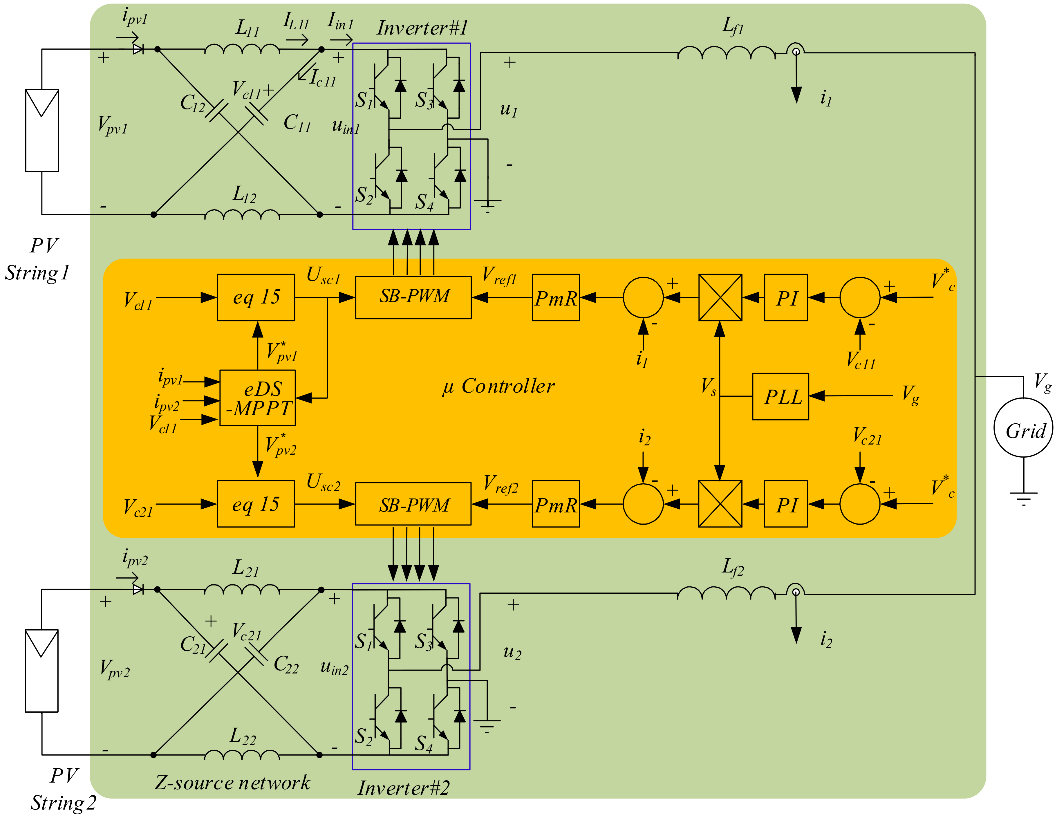
The proposed configuration is shown in Figure 3. This structure includes two AC modules; each of them has a PV string and a ZSI connected to the grid through an inductor. A typical microcontroller can be used to control both ZSIs simultaneously where the control scheme uses grid voltage, ZSI outputs currents, capacitor voltages of the ZSI network, and PV string currents for MPPT and exchanging with the grid.
Each ZSI includes the Z-source X shape and symmetrical network (C, L) and full-bridge inverter (S1–S4) [11]. The conventional voltage source inverter (VSI) has two zero vectors and two active vectors. In the ZSI, a shoot-through vector is added to these vectors. A DC terminal of the inverter bridge, uin, is short-circuited through upper and lower switches of one or two legs in shoot-through mode. The shoot-through vector creates voltage boost capability for the ZSI, and this inverter would be able to produce the desired AC voltage despite variations of the DC voltage source [39].
If the equations governing the Z-source network are written in shoot-through and non-shoot-through modes, then uin can be described as follows [40]:
in which Vpv is the PV string output voltage, B is the boost coefficient, and i indicates the ZSI’s number. The B value is determined as follows:
If T0 is the shoot-through vector interval in each switching period T, then the shoot-through duty cycle, D0, will be calculated as:
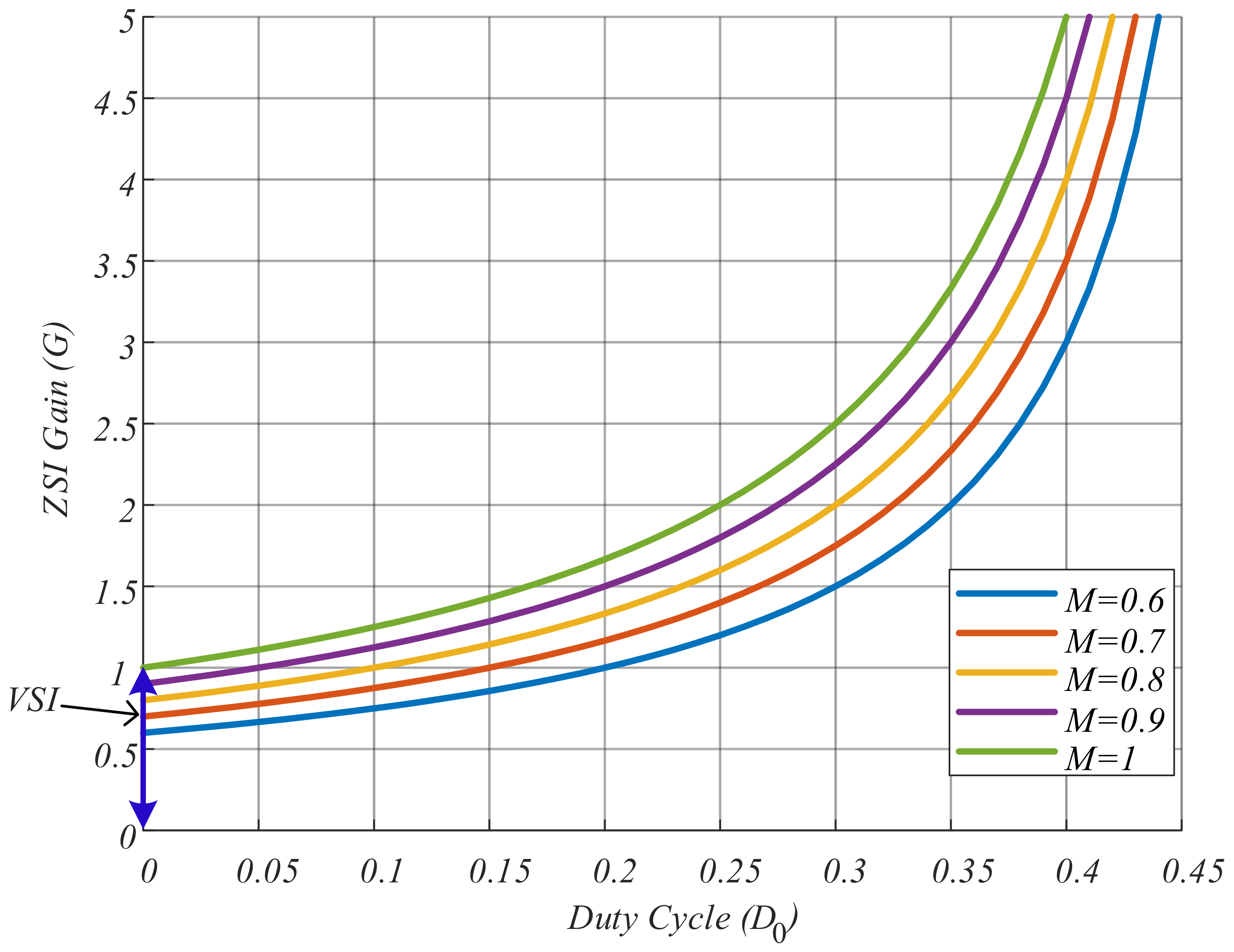
In theory, the steady-state shoot-through duty ratio D0 in Equation (3) can be between 0 and 0.5; however, it should be limited in practice by the zero-vector interval to avoid output voltage distortion. The peak value of output AC voltage ui and capacitor voltages can be expressed related as follows [41]:
where M is the modulation index.
The ZSI gain (G) is drawn based on the shoot-through duty cycle and the modulation index in Figure 4, wherein ZSI with having two control inputs, M and D0, can produce any voltage in the AC side. On the other hand, VSI with only one control variable M, as a buck converter, can only generate AC voltage less than DC link voltage, and using a DC/DC converter is mandatory between PV array and VSI [29,42].
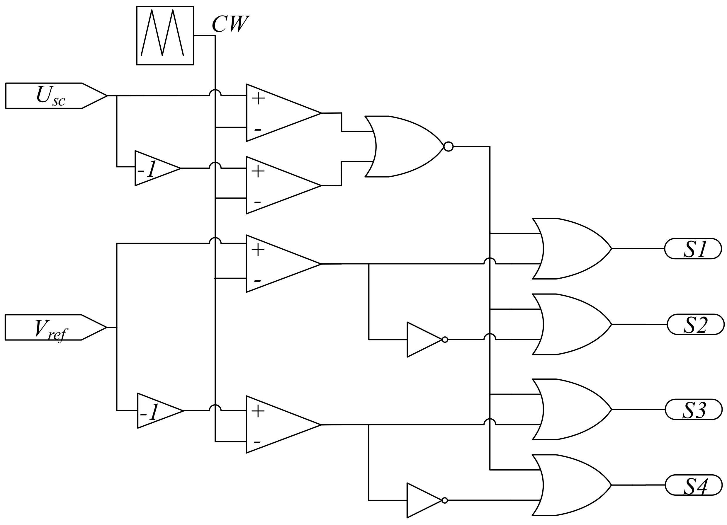
Figure 5 and Figure 6 show the principle and implementation of the simple boost PWM method (SB-PWM) for switching of ZSI. The AC output voltage of ZSI is produced based on Vref, and the boost coefficient (B) is controlled by Usc. Usc and -Usc are two straight lines, which are used as shoot-through signals in this method. When a carrier wave (CW) is larger than Usc or smaller than -Usc, a shoot-through vector is created for ZSI. The Usc value is equal to:
3. Proposed Control Method
The control system of each ZSI consists of two parts—controlling power delivered to the grid and tracking of the MPP.
3.1. Controlling Power Delivered to the Grid
For controlling the exchanged power with the grid, a dual-loop control system is utilized (see Figure 3): an inner current control loop and an outer capacitor voltage control loop to control the value of the injected power to the grid.
3.1.1. Inner Current Control Loop
In this system, as shown in Figure 3, the grid current can be described as follows:
where s, Vg, ii, and Lf are Laplace operator, grid voltage, and grid current, filter inductor, respectively. The following equation is obtained by substituting ui ≅ Vref Vc,i1 into Equation (7):
Based on Equation (8), when the capacitor voltage of the ZSI is constant, by changing Vref (voltage reference), the AC grid current can be controlled. As a result, a PmR controller is applied to define Vref for controlling the grid current:
where ω is 2πf and f is the grid frequency. Using this controller leads to the harmonic content reduction in the injected current to the grid because of restricting the odd harmonics [43].
3.1.2. Voltage Controller of the ZSI Capacitor
If the voltages of the capacitors of the Z-source network are reduced too much, the inverter bridge will not be able to produce proper AC voltage by changing the modulation index, which will result in injecting a non-sinusoidal current of the grid. If the voltages of the capacitors of the Z-source network increase too much, Z-source capacitors or switches of the inverter bridge would be damaged. Therefore, an outer voltage control loop is needed to control and stabilize the capacitor voltage of Z-source network. When power loss is ignored, the following equation would be true concerning DC and AC powers:
where Iin is the average current of DC link of the input inverter bridge, Vg,rms and ii,rms are the RMS values of voltage and current of the grid. Equation (10) can be rewritten as:
Given the topology of the Z-source network in Figure 3:
In the steady-state, the inductor current of the Z-source network is constant. Hence, based on Equations (11) and (12), the capacitor voltage of the Z-source network can be controlled by the inverter current Iin. Therefore, the capacitor voltage is compared with its reference value and a PI controller is used for producing the reference value of the grid current as shown in Figure 3.
3.2. Proposed MPPT Method
In the MPP, the incremental resistance of the PV string is equal to [44]:
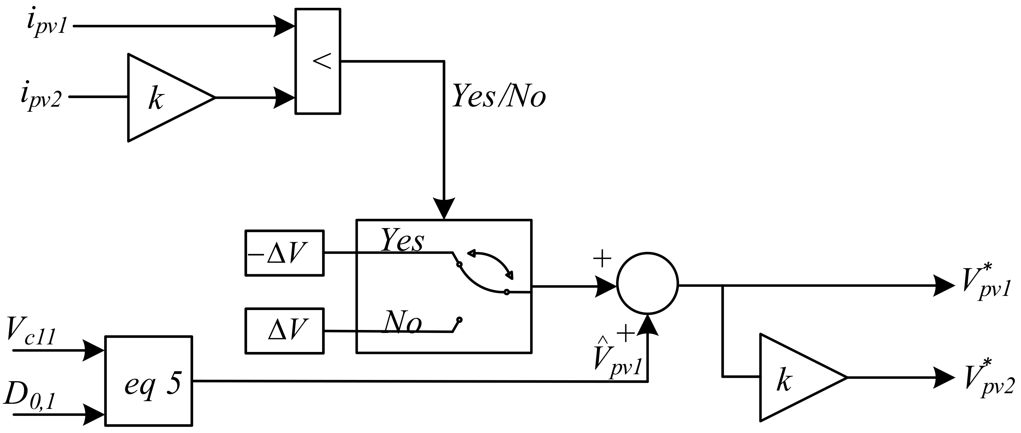
Therefore, it can be determined that the operating point is on the left or the right side of the MPP point by monitoring I-V characteristics of the string according to Equation (13) [45]. In the parallel operation of the two strings, the I-V curve slope is easily calculated by using the difference between the voltage and current of strings. Figure 7 shows the proposed eDS-MPPT algorithm flowchart. The voltage of ZSI network capacitor, Vc11, is already used to control DC link voltage; therefore, Vc11 and shoot-through duty cycle are used for calculating the voltage PV string, V^pv1, to avoid using voltage sensors across the PV strings. The eDS-MPPT is developed by simple mathematical calculations based on PV currents and the calculated PV voltage. The eDS-MPPT does not require memory to store current and previous comparison. Moreover, the PV system operates in MPP without any fluctuation because the eDS-MPPT finds MPP by comparing the currents of strings, unlike some other methods such as P&O [33], which use current and previous values for finding MPP.
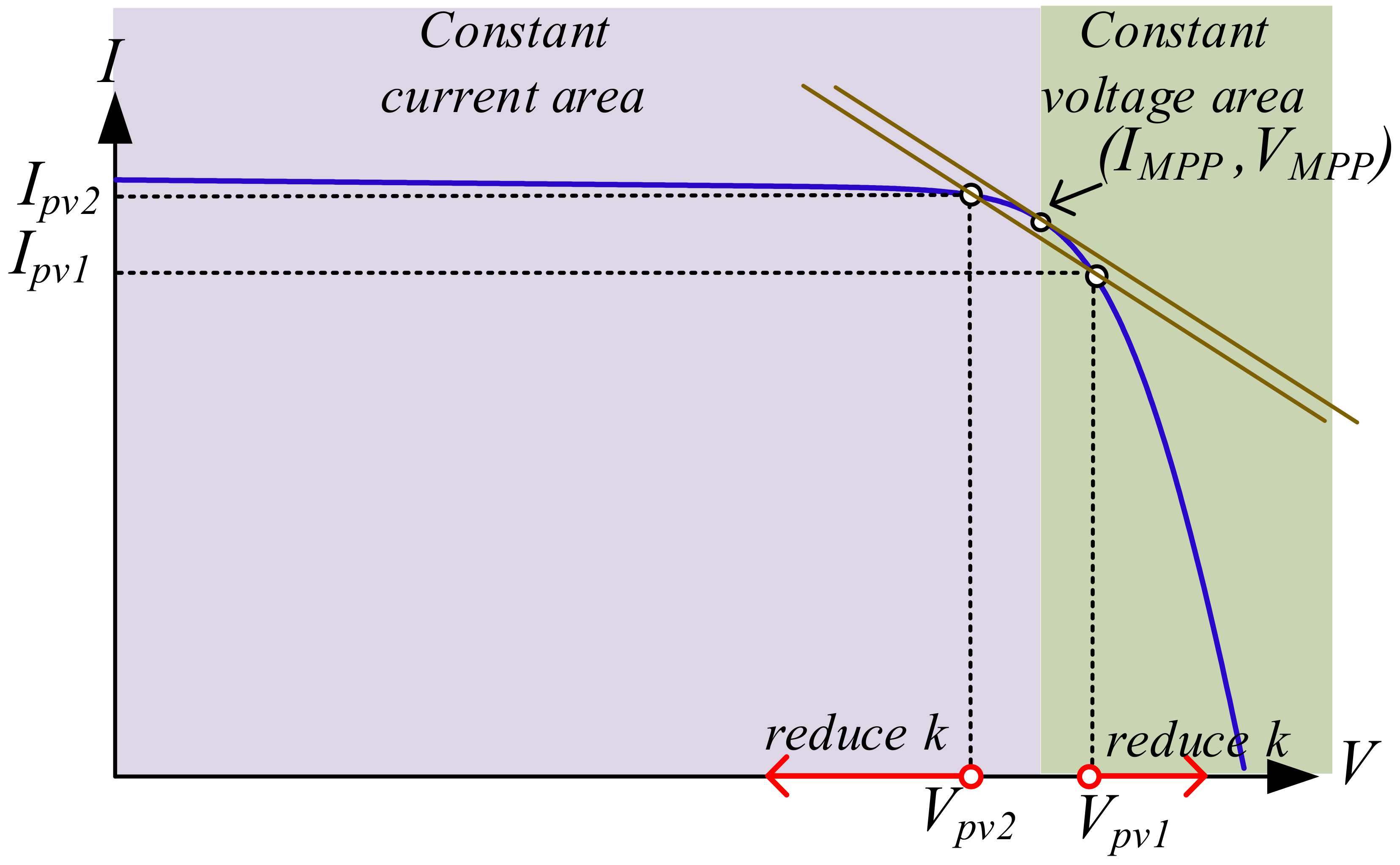
Figure 8 and Figure 9 explain how eDS-MPPT works. In Figure 8, Vpv1/ipv1 and Vpv2/ipv2 are, respectively, the voltage/current of PV string 1 and 2. At first, when Vpv1 increases, the Vpv2 value becomes equal to kVpv1, in which k is a constant value less than 1. Then, currents of strings are compared; if ipv1 < k ipv2, the operating point is located in the constant–voltage area of the power curve (Figure 9). In this case, the string voltage must be reduced for obtaining MPP.
On the other hand, if ipv1 > k ipv2, the operating point is located in the constant–current area (Figure 8). In this case, the string voltage must increase for obtaining MPP. In the steady-state, output powers of both strings are the same (Vpv1 × ipv1 = Vpv2 × ipv2), and the following relations exist between the two operating points:
while k is less than or equal to 1, the incremental resistance of the string is approximated by the line slope connecting the operating points of the two strings. If k moves to one, Vpv1 and Vpv2 will also tend to VMPP. As shown in Figure 9, since the output powers of the two strings are the same, the maximum power point will be located between the strings operating points. In total, k should be in the range of 0.9 and 0.95 because output powers of PV strings deviated from PMPP in the case of small k values.
As it is illustrated in Figure 3, after determining PV voltage reference by eDS-MPPT algorithm, shoot-through signals, Usc, are calculated as follows:
4. Simulation Results
For verifying the performance of the proposed system, the system of Figure 3 is simulated in MATLAB/SIMULINK. In the simulations, two photovoltaic strings are connected to a 110 V, 50 Hz grid through the ZSIs. The ZSIs parameters are given in Table 1, and each ZSI is interfaced to the grid through a 1 mH inductor. The parameters of PV strings are listed in Table 2. A 110 uF capacitor is installed in parallel to each PV string to reduce the level of PV current ripple and low-frequency voltage ripples. The controllers are tuned to ensure the best performance in the steady-state and transient situations, and their parameters are listed in Table 3. The sampling period of the simulation is set 2 µs and switching frequencies of both ZSIs are 20 kHz. Since the DC link voltage of ZSI, Vin, must be enough higher than the peak value of grid voltage (156 V), the reference of capacitor voltage is selected 170V. Therefore, Vin and modulation index of ZSI will be regulated around 240 V and 0.65, respectively.
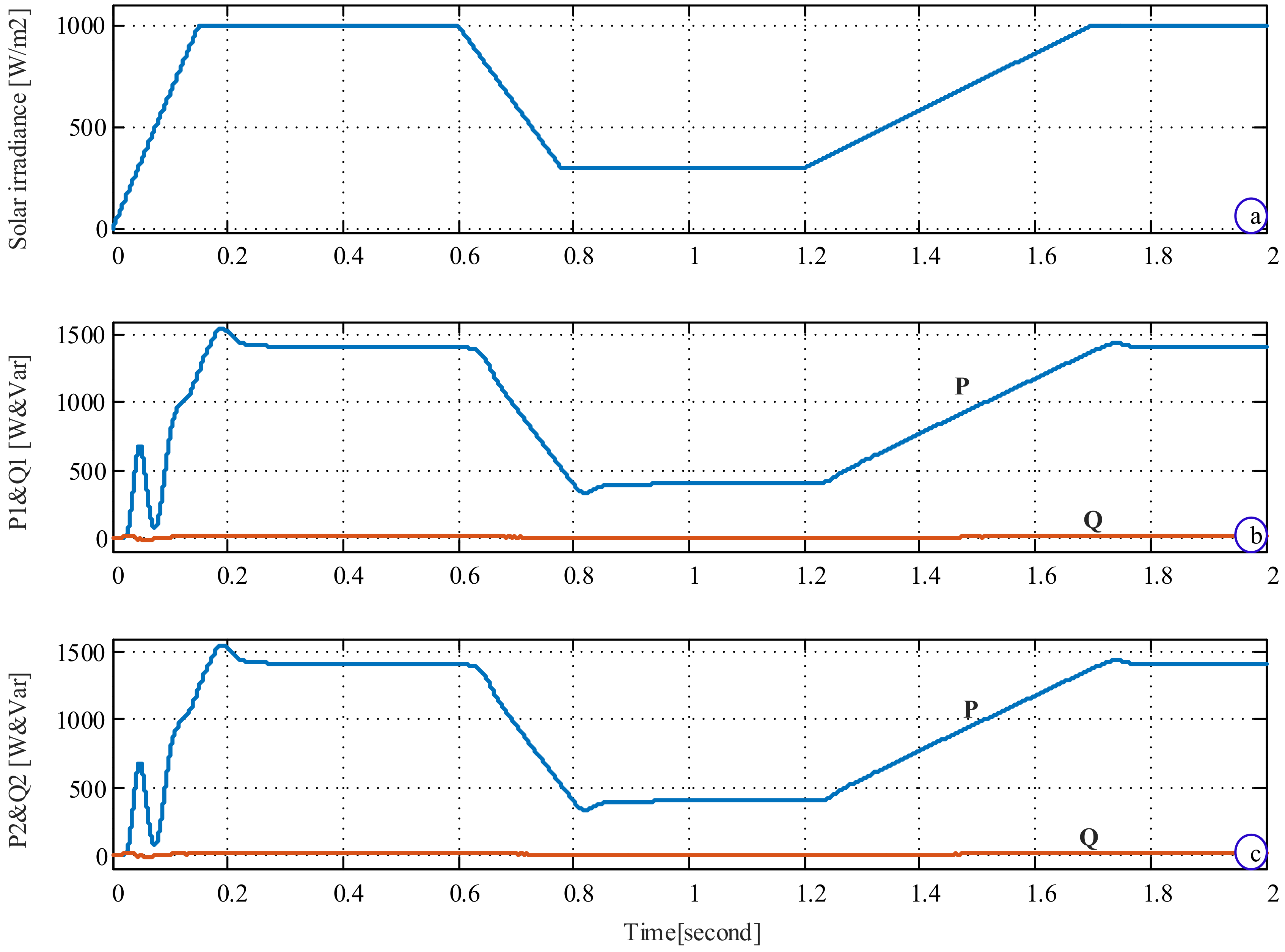
As shown in Figure 10, the solar irradiance is changed from 1000 W/m2 to 300 W/m2 and vice versa for investigating the MPPT method performance. For evaluating the control scheme, both the ideal grid with sinusoidal voltage and distorted grid with high values of harmonics are considered. The grid voltage is considered sinusoidal until t = 1.2 s and then 10% of fifth and seventh harmonics, equal to total harmonic distortion (THD) of 14%, is added to the grid voltage. It is evident in Figure 10 that both ZSIs inject active power (P) under solar irradiance changes, and the exchanged reactive powers (Q) with the grid are regulated around zero, i.e., unity power factor operation.
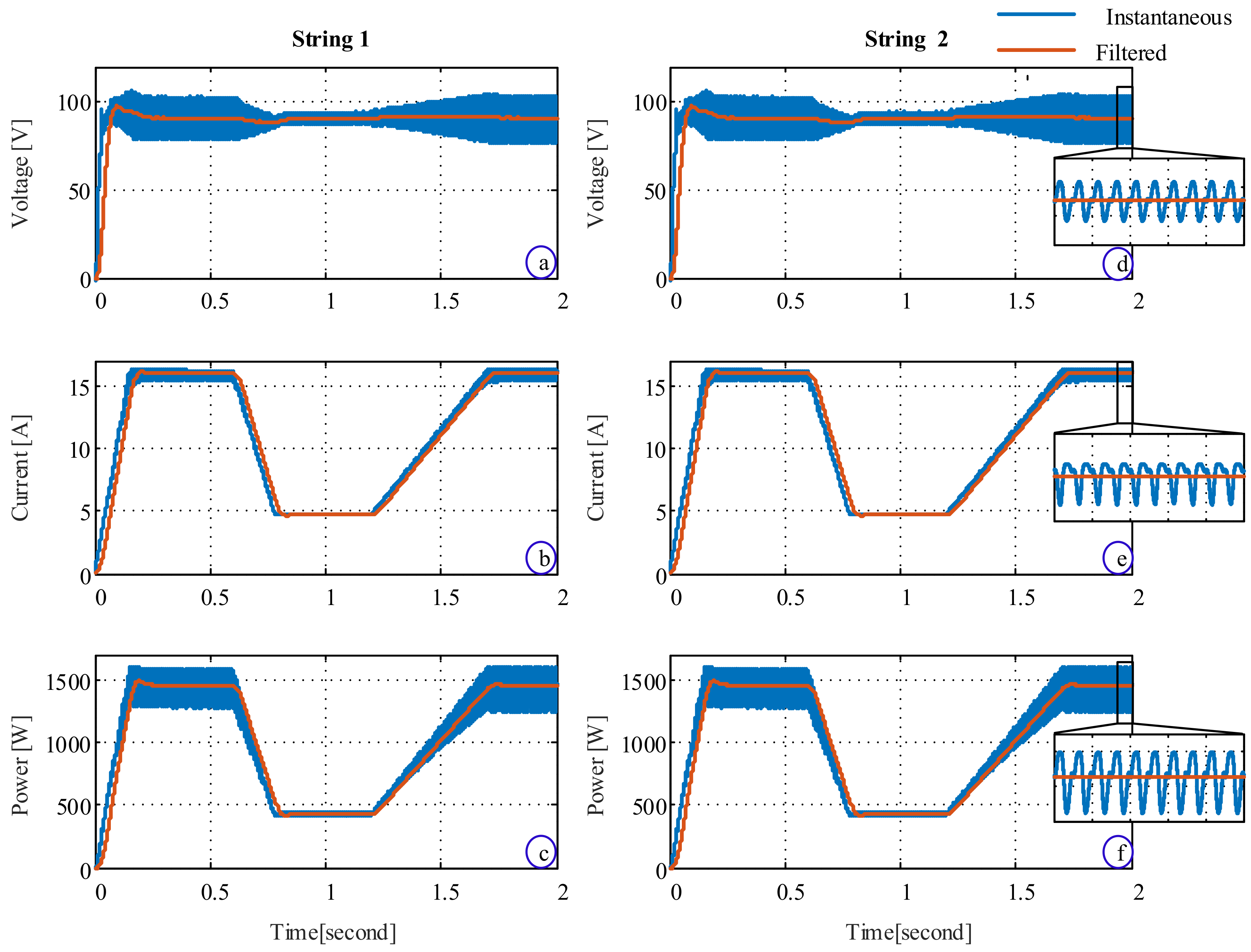
The instantaneous and filtered (average) values of voltage, current, and power of PV strings are presented in Figure 11. Since ZSIs are connected to a single-phase grid, all variables have typical 100 Hz ripples [47]. Figure 11 shows that ZSIs with the eDS-MPPT method accurately harvest the maximum powers of PV strings where the peak values of powers are close to MPP values (PMPP = 1600 W) and static MPPT efficiency is around 93.4%. The PV strings’ voltages do not change dramatically in Figure 11a,d, but the strings’ currents have changed in proportion to the solar irradiance in Figure 11b,e. Therefore, the presented results in Figure 11 proved the performance of the proposed PCS with eDS-MPPT in absorbing maximum power from PV strings.
Figure 12 is presented to evaluate the adequacy of the proposed PCS in injecting high-quality currents to the grid. The injected currents are kept sinusoidal and in phase with the grid voltage for both sinusoidal and distorted grid voltages. As an example, the harmonic spectrum of the ZSI1 current is displayed in Figure 13. It is observed that THD of current is around 3.2%, and all current harmonic components are less than 0.6%. Therefore, the tuned PmR controller has a highly desirable performance, and the ZSI currents comply with the power quality requirements of IEEE 1547 [48].
The capacitors voltages, Vc11 and Vc21, and DC link voltages of the Z-source networks, uin1 and uin2, are shown in Figure 14. It can be observed that the voltages of the capacitors are accurately controlled around their voltage references at 170 V. In this system, the DC link voltages jump to zero during shoot-through time intervals to track MPPs, as mentioned in Section 3.2.
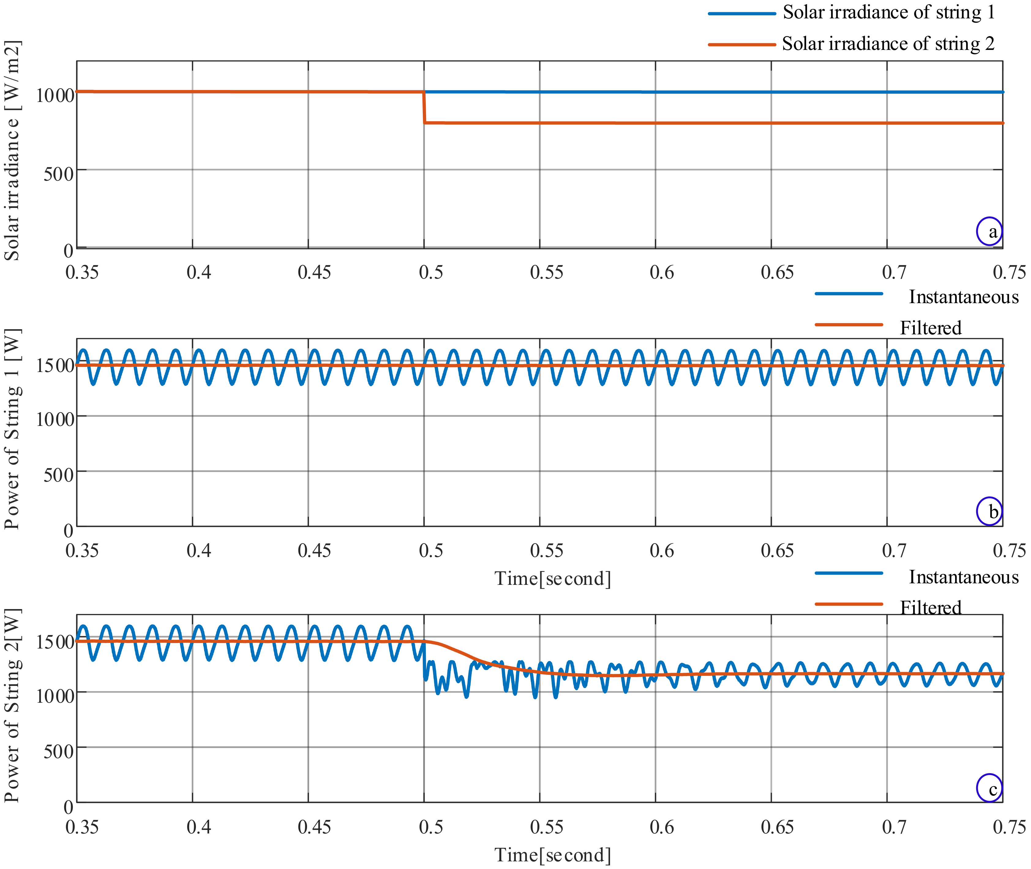
Figure 15 demonstrates the effectiveness of eDS-MPPT for unequal solar irradiances. Until t = 0.5 s, the solar irradiances of both strings are the same, 1000 W/m2, and then, the solar irradiance for string 2 steps down to 800 W/m2, while that of string 1 is still 1000 W/m2 (see Figure 15a). It can be seen from Figure 15b,c that the maximum value of string 1 power is around 1600 W in the whole simulation, while the respective value of power string 2 reduces from 1600 to 1260 W (the expected value is 1300 W) at t = 0.5 s in response to the solar irradiance change. These results show that eDS-MPPT can track MPP in case of unequal solar irradiances with static MPPT efficiency around 91.1%.
In summary, the proposed parallel ZSIs as a single-stage PCS has fewer numbers of semiconductors compared to conventional PCSs. The proposed control scheme injects a low THD current with unity power factor to the grid with both sinusoidal and distorted grid voltages. On the other hand, the static MPPT efficiency of the proposed PCS with eDS-MPPT for equal and unequal solar irradiances is around 93.4% and 91.1%, respectively. Last but not least, this method reduces two voltage sensors compared to other PCSs. Therefore, it is a suitable candidate for multi-string PV systems.
5. Conclusions
A new structure of the parallel Z-source inverters (ZSIs) has been presented for single-phase grid-connected photovoltaic systems. The operation principles of the parallel ZSIs were analyzed, and then, a cascaded control scheme with inner and outer loops for AC side as well as a controller for the DC side of ZSIs was developed to harvest and inject the PV string powers to the grid. The inner control loop controls the modulation index in a way that the maximum active power of PV was injected to the grid, and the grid current is kept sinusoidal (THD ≅ 3%) with a unity power factor. The outer control loop was used to stabilize the capacitor voltage of the Z-source network by controlling the magnitude of the grid current. The maximum power points of the PV strings were tracked via the shoot-through vectors of ZSIs by proposed enhanced dual-string maximum power point tracker (eDS-MPPT) in the feedforward pass. By conducting various simulations, it was shown that: 1) the proposed system is able to inject the maximum power of the PV strings to the grid with a high-quality and unity-power-factor current; 2) the eDS-MPPT performed appropriately with only using the currents of the strings without a significant computational burden.
Author Contributions
M.S. (Mahdi Shahparasti) is the main researcher who initiated and organized research reported in the paper. He contributed to the sections on ZSI modelling and controlling, control algorithm development, and validation. In addition, as the first author, he is responsible for writing the main parts of the paper, including paper layout and results. M.S. (Mehdi Savaghebi) contributed to analysis, writing, and editing of the manuscript. M.E.A. contributed to drafting the article. T.E. contributed towards the editing of the manuscript. All authors have read and agreed to the published version of the manuscript.
Funding
This research received no external funding.
Conflicts of Interest
The authors declare no conflict of interest.
Nomenclature
| AC | Alternating current |
| B | The boost coefficient |
| L | Inductor of Z-source network |
| C | Capacitor of Z-source network |
| CW | Carrier wave |
| D0 | Shoot-through duty cycle |
| DC | Direct Current |
| i | Current of the converter in AC side |
| irms | Current of the grid |
| Iin | Input current of inverter bridge |
| G | ZSI gain |
| k | MPPT tracking coefficient |
| kpdc | Integral gain of capacitor voltage controller |
| kp | Proportional gain of current controller |
| kpdc | Proportional gain of capacitor voltage controller |
| ki | Resonant gain of current controller |
| M | Modulation index of inverter |
| MPP | Maximum power point |
| MPPT | Maximum power point tracking |
| Lf1, Lf2 | Inductor of L filters |
| P | Active power injected by the inverter to the grid |
| PR | Proportional-resonant controller |
| Q | Reactive power injected by the inverter to the grid |
| S1, S2, S3, S4 | Semiconductor switches |
| s | Laplace operator |
| SB-PWM | Simple Boost Pulse Width Modulation |
| T0 | Shoot-through vector interval |
| T | Switching period |
| u1, u2 | Inverter output voltage |
| uin1, uin2 | Inverter DC link voltage |
| Usc | Shoot-through signal |
| Vref | Reference of switching modulator |
| Vpv1, Vpv2 | PV strings voltages |
| Vg | Grid voltage |
| ωo | Fundamental resonant frequency in rad/s |
Subscripts and Superscripts
| 1, 2 | ZSI 1 and 2 |
| C | Capacitor of Z-source network |
| i | ZSI’s number indicator |
| L | Inductor of Z-source network |
| in | DC link of inverter |
| g | Grid |
| max | Maximum |
| MPP | Maximum power point |
| pv | PV string |
| rms | RMS |
| * | Reference |
| ^ | Calculated value |
References
- Shahparasti, M.; Mohamadian, M.; Parsa Moghaddam, M.; Teimourzadeh Baboli, P.; Haghifam, M.R. Energy management and operation modelling of hybrid AC–DC microgrid. IET Gener. Transm. Distrib. 2014, 8, 1700–1711. [Google Scholar] [CrossRef]
- Shahparasti, M.; Mohamadian, M.; Teimourzadeh Baboli, P.; Yazdian, A.; Member, S.; Mohamadian, M. Toward Power Quality Management in Hybrid AC—DC Microgrid Using LTC-L Utility Interactive Inverter: Load Voltage—Grid Current Tradeoff. IEEE Trans. Smart Grid 2015, 8, 1–11. [Google Scholar] [CrossRef]
- Ahmad, M.W.; Kumar, P.N.; Arya, A.; Anand, S. Noninvasive technique for DC-link capacitance estimation in single-phase inverters. IEEE Trans. Power Electron. 2018, 33, 3693–3696. [Google Scholar] [CrossRef]
- Varaprasad, O.V.S.R.; Bharath Kumar, D.; Siva Sarma, D.V.S.S. Three level hysteresis current controlled vsi for power injection and conditioning in grid connected solar pv systems. In Proceedings of the 2014 IEEE International Conference on Power Electronics, Drives and Energy Systems (PEDES), Mumbai, India, 16–19 December 2014; pp. 1–5. [Google Scholar] [CrossRef]
- Chang, C.H.; Chang, E.C.; Cheng, H.L. A high-efficiency solar array simulator implemented by an LLC resonant DC-DC converter. IEEE Trans. Power Electron. 2013, 28, 3039–3046. [Google Scholar] [CrossRef]
- Yan, Y.; Xiang, L.; Dianfeng, W. Integrated Solutions for Photovoltaic Grid Connection: Increasing the Reliability of Solar Power. IEEE Power Energy Mag. 2014, 12, 84–91. [Google Scholar] [CrossRef]
- Romero-Cadaval, E.; Spagnuolo, G.; Franquelo, L.G.; Ramos-Paja, C.A.; Suntio, T.; Xiao, W.M. Grid-connected photovoltaic generation plants: Components and operation. IEEE Ind. Electron. Mag. 2013, 7, 6–20. [Google Scholar] [CrossRef] [Green Version]
- Jeon, Y.T.; Park, J.H. Unit-Minimum Least Power Point Tracking for the Optimization of Photovoltaic Differential Power Processing Systems. IEEE Trans. Power Electron. 2018, 34, 311–324. [Google Scholar] [CrossRef]
- De Freitas Takami, M.H.; Oliveira Da Silva, S.A.; Sampaio, L.P. Dynamic performance comparison involving grid-connected PV systems operating with active power-line conditioning and subjected to sudden solar irradiation changes. IET Renew. Power Gener. 2019, 13, 587–597. [Google Scholar] [CrossRef]
- Koran, A.; LaBella, T.; Lai, J.S. High Efficiency Photovoltaic Source Simulator with Fast Response Time for Solar Power Conditioning Systems Evaluation. IEEE Trans. Power Electron. 2014, 29, 1285–1297. [Google Scholar] [CrossRef]
- Kouro, S.; Leon, J.I.; Vinnikov, D.; Franquelo, L.G. Grid-connected photovoltaic systems: An overview of recent research and emerging PV converter technology. IEEE Ind. Electron. Mag. 2015, 9, 47–61. [Google Scholar] [CrossRef]
- Bacha, S.; Picault, D.; Burger, B.; Etxeberria-Otadui, I.; Martins, J. Photovoltaics in microgrids: An overview of grid integration and energy management aspects. IEEE Ind. Electron. Mag. 2015, 9, 33–46. [Google Scholar] [CrossRef]
- Shahparasti, M.; Sadeghi Larijani, A.; Fatemi, A.; Yazdian Varjani, A.; Mohammadian, M. Quasi Z-source inverter for photovoltaic system connected to single phase AC grid. In Proceedings of the 2010 1st Power Electronic & Drive Systems & Technologies Conference (PEDSTC), Tehran, Iran, 17–18 February 2010; pp. 456–460. [Google Scholar] [CrossRef]
- ABB Solar Inverters—ABB String Inverters—PVS-100/120-TL. 2017, pp. 98–101. Available online: https://new.abb.com/products/6AGC069647/pvs-120-tl-sx2-full-inverter (accessed on 29 September 2020).
- Baumann, C. 4-Level Inverter UPS. 2020. Available online: https://7x24exchangerm.org/images/downloads/2017_Presentations/3_7x24_presentation_carsten_revised_4_level_ups_7x24_colorado.pdf (accessed on 29 September 2020).
- Honarmand, S.; Rajaei, A.; Shahparasti, M.; Luna, A.; Pouresmaeil, E. A Modified Partial Power structure for Quasi Z-Source Converter to Improve Voltage Gain and Power Rating. Energies 2019, 12, 2139. [Google Scholar] [CrossRef] [Green Version]
- Guo, X.; Yang, Y.; Wang, B.; Blaabjerg, F. Leakage Current Reduction of Three-Phase Z-Source Three-Level Four-Leg Inverter for Transformerless PV System. IEEE Trans. Power Electron. 2019, 34, 6299–6308. [Google Scholar] [CrossRef]
- Sajadian, S.; Ahmadi, R.; Zargarzadeh, H. Extremum Seeking-Based Model Predictive MPPT for Grid-Tied Z-Source Inverter for Photovoltaic Systems. IEEE J. Emerg. Sel. Top. Power Electron. 2019, 7, 216–227. [Google Scholar] [CrossRef]
- Hanif, M.; Basu, M.; Gaughan, K. Understanding the operation of a Z-source inverter for photovoltaic application with a design example. IET Power Electron. 2011, 4, 278–287. [Google Scholar] [CrossRef]
- Zhang, J. Unified control of Z-source grid-connected photovoltaic system with reactive power compensation and harmonics restraint: Design and application. IET Renew. Power Gener. 2018, 12, 422–429. [Google Scholar] [CrossRef]
- Zhang, X.; Fu, Z.; Xiao, Y.; Wang, G.; Xu, D. Control of parallel three-phase PWM converters under generalized unbalanced operating conditions. IEEE Trans. Power Electron. 2017, 32, 3206–3215. [Google Scholar] [CrossRef]
- Chen, Y.; Tan, R.; Zheng, Y.; Zhou, Z. Sliding-mode control with multipower approaching law for dc-link voltage of z-source photovoltaic inverters. IEEE Access 2019, 7, 133812–133821. [Google Scholar] [CrossRef]
- Lashab, A.; Sera, D.; Guerrero, J.M.; Mathe, L.; Bouzid, A. Discrete Model-Predictive-Control-Based Maximum Power Point Tracking for PV Systems: Overview and Evaluation. IEEE Trans. Power Electron. 2018, 33, 7273–7287. [Google Scholar] [CrossRef]
- Vu, P.; Nguyen, Q.; Tran, M.; Todeschini, G.; Santoso, S. Adaptive backstepping approach for dc-side controllers of Z-source inverters in grid-tied PV system applications. IET Power Electron. 2018, 11, 2346–2354. [Google Scholar] [CrossRef] [Green Version]
- Huang, Y.; Wang, H.; Khajepour, A.; He, H.; Ji, J. Model predictive control power management strategies for HEVs: A review. J. Power Sources 2017, 341, 91–106. [Google Scholar] [CrossRef]
- Vilathgamuwa, D.M.; Gajanayake, C.J.; Loh, P.C. Modulation and control of three-phase paralleled Z-source inverters for distributed generation applications. IEEE Trans. Energy Convers. 2009, 24, 173–183. [Google Scholar] [CrossRef]
- Sonkar, S.P.; Lal, V.N.; Singh, R.K. Three-phase quasi-Z source inverters with regulated multiple AC outputs for microgrid applications and three-phase residential load. IET Power Electron. 2020, 13, 2222–2235. [Google Scholar] [CrossRef]
- Aleem, Z.; Shin, D.; Cha, H.; Lee, J.P.; Yoo, D.W.; Peng, F.Z. Parallel operation of inverter using trans-Zsource network. IET Power Electron. 2015, 8, 2176–2183. [Google Scholar] [CrossRef]
- Shahparasti, M.; Yazdian, A.; Mohamadian, M.; Larijani, A.S.S.; Fatemi, A. Parallel uninterruptible power supplies based on Z-source inverters. IET Power Electron. 2012, 5, 1359. [Google Scholar] [CrossRef]
- Gajanayake, C.J.; Teodorescu, R.; Blaabjerg, F.; Vilathgamuwa, D.M.; Loh, P.C. Four-leg parallel Z-source inverter based DG systems to enhance the grid performance under unbalanced conditions. In Proceedings of the 2007 European Conference on Power Electronics and Applications, Aalborg, Denmark, 2–5 September 2007. [Google Scholar] [CrossRef]
- Al Nabulsi, A.; Dhaouadi, R. Efficiency optimization of a dsp-based standalone PV system using fuzzy logic and dual-MPPT control. IEEE Trans. Ind. Inform. 2012, 8, 573–584. [Google Scholar] [CrossRef]
- Park, J.H.; Ahn, J.Y.; Cho, B.H.; Yu, G.J. Dual-module-based maximum power point tracking control of photovoltaic systems. IEEE Trans. Ind. Electron. 2006, 53, 1036–1047. [Google Scholar] [CrossRef]
- Kumar, N.; Hussain, I.; Singh, B.; Panigrahi, B.K. Framework of Maximum Power Extraction from Solar PV Panel Using Self Predictive Perturb and Observe Algorithm. IEEE Trans. Sustain. Energy 2018, 9, 895–903. [Google Scholar] [CrossRef]
- Killi, M.; Samanta, S. Modified perturb and observe MPPT algorithm for drift avoidance in photovoltaic systems. IEEE Trans. Ind. Electron. 2015, 62, 5549–5559. [Google Scholar] [CrossRef]
- Sera, D.; Mathe, L.; Kerekes, T.; Spataru, S.V.; Teodorescu, R. On the perturb-and-observe and incremental conductance mppt methods for PV systems. IEEE J. Photovolt. 2013, 3, 1070–1078. [Google Scholar] [CrossRef]
- Kumar, N.; Hussain, I.; Singh, B.; Panigrahi, B.K. Self-Adaptive Incremental Conductance Algorithm for Swift and Ripple-Free Maximum Power Harvesting from PV Array. IEEE Trans. Ind. Inform. 2018, 14, 2031–2041. [Google Scholar] [CrossRef]
- Wang, H.; Shen, J. An Improved Model Combining Evolutionary Algorithm and Neural Networks for PV Maximum Power Point Tracking. IEEE Access 2019, 7, 2823–2827. [Google Scholar] [CrossRef]
- Tang, S.; Sun, Y.; Chen, Y.; Zhao, Y.; Yang, Y.; Szeto, W. An Enhanced MPPT Method Combining Fractional-Order and Fuzzy Logic Control. IEEE J. Photovolt. 2017, 7, 640–650. [Google Scholar] [CrossRef]
- Kong, X.; Wong, C.K.; Lam, C.S. Effects of Parasitic Resistances on Magnetically Coupled Impedance-Source Networks. IEEE Trans. Power Electron. 2020, 35, 9171–9183. [Google Scholar] [CrossRef]
- Ding, X.; Qian, Z.; Xie, Y.; Lu, Z. Three-Phase Z-Source Rectifier. In Proceedings of the 2005 IEEE 36th Power Electronics Specialists Conference, Recife, Brazil, 16 June 2005; pp. 494–500. [Google Scholar]
- Fang Zheng, P.; Peng, F.Z.; Member, S. Z-Source Inverter. IEEE Trans. Ind. Appl. 2003, 39, 504–510. [Google Scholar] [CrossRef]
- Venkatramanan, D.; Adapa, A.K.; John, V. Design and comparative study of discrete and module-based IGBT power converters. Sadhana Acad. Proc. Eng. Sci. 2017, 42, 1401–1409. [Google Scholar] [CrossRef] [Green Version]
- Shahparasti, M.; Rocabert, J.; Muñoz, R.S.; Luna, A.; Rodríguez, P. Impedance Source Interlinking Converter for Microbial Electrosynthesis Energy Storage Applications. In Proceedings of the 2018 7th International Conference on Renewable Energy Research and Applications (ICRERA), Paris, France, 14–17 October 2018; pp. 1340–1345. [Google Scholar]
- Esram, T.; Chapman, P.L. Comparison of photovoltaic array maximum power point tracking techniques. IEEE Trans. Energy Convers. 2007, 22, 439–449. [Google Scholar] [CrossRef] [Green Version]
- Lopez-Santos, O.; Garcia, G.; Martinez-Salamero, L.; Giral, R.; Vidal-Idiarte, E.; Merchan-Riveros, M.C.; Moreno-Guzman, Y. Analysis, design, and implementation of a static conductance-based MPPT method. IEEE Trans. Power Electron. 2019, 34, 1960–1979. [Google Scholar] [CrossRef]
- Villalva, M.G.; Gazoli, J.R.; Filho, E.R. Comprehensive approach to modeling and simulation of photovoltaic arrays. IEEE Trans. Power Electron. 2009, 24, 1198–1208. [Google Scholar] [CrossRef]
- Siu, K.K.M.; Ho, C.N.M. System Model and Performance Evaluation of Single-Stage Buck-Boost Type Manitoba Inverter for PV Applications. IEEE J. Emerg. Sel. Top. Power Electron. 2019, 8, 3457–3466. [Google Scholar] [CrossRef]
- IEEE 1547-2003—IEEE Standard for Interconnecting Distributed Resources with Electric Power Systems. Available online: https://0-standards-ieee-org.brum.beds.ac.uk/standard/1547-2003.html (accessed on 20 April 2019).
Figure 1.
Centralized structure of the grid-connected photovoltaic systems.
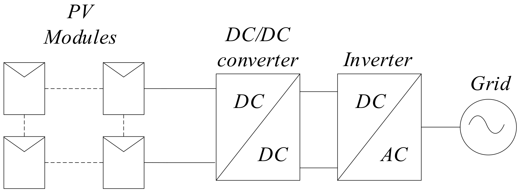
Figure 2.
Parallel structure of the grid-connected photovoltaic systems.
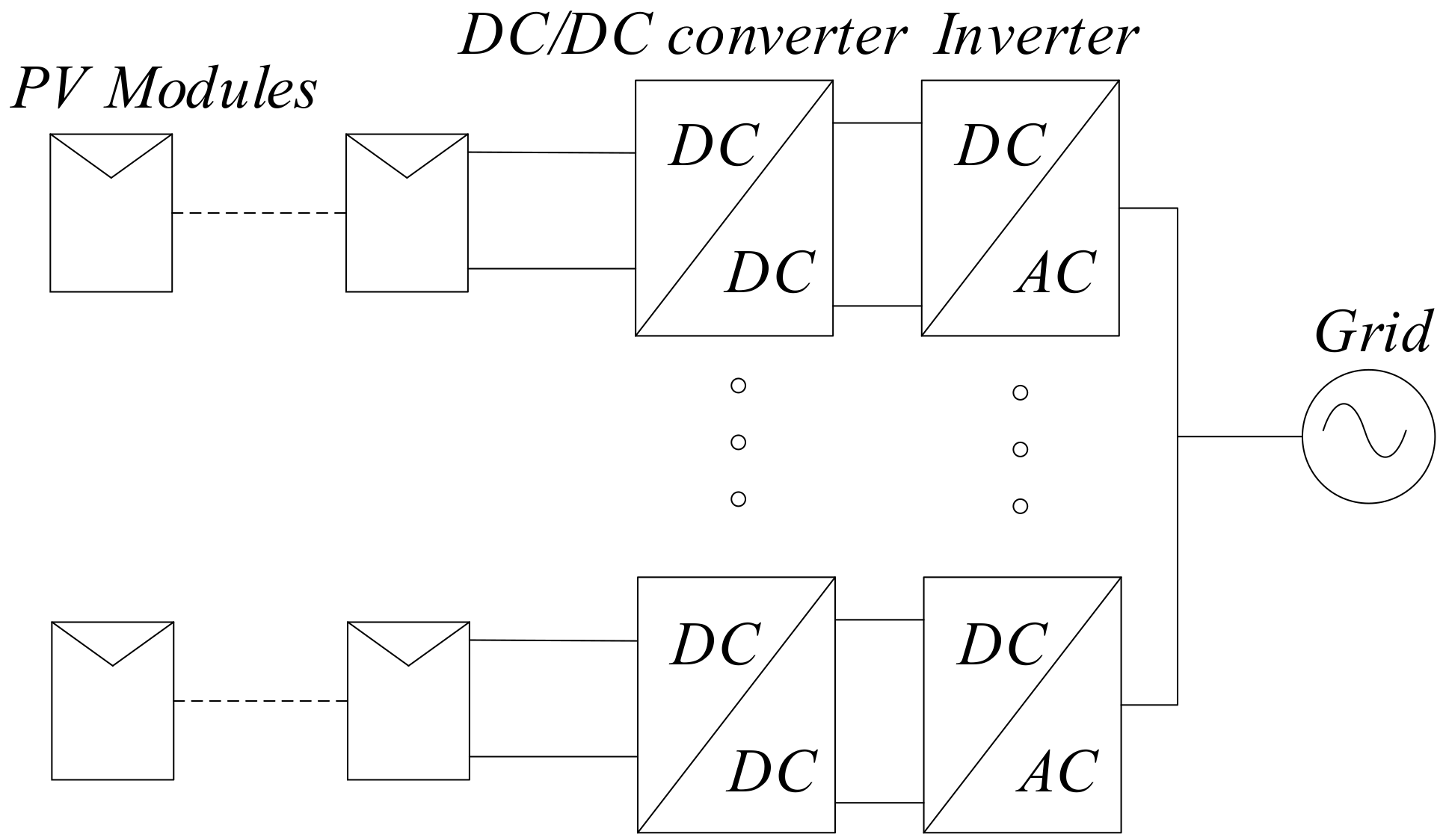
Figure 3.
Configuration of the proposed system.

Figure 4.
Gain of Z-source inverter based on D0 and M.

Figure 5.
Simple boost switching method for the Z-source inverters (ZSI).
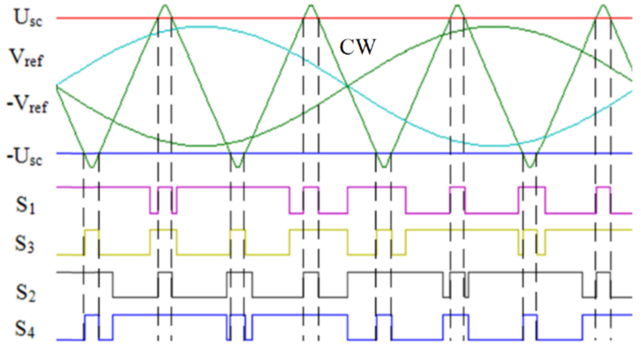
Figure 6.
Implementation of simple boost switching method.

Figure 7.
Flowchart of the proposed enhanced dual-string maximum power point tracking (eDS-MPPT) method.
Figure 7.
Flowchart of the proposed enhanced dual-string maximum power point tracking (eDS-MPPT) method.

Figure 8.
Relationship between operating points of two strings and VMPP on I-V curve.

Figure 9.
Relationship between operating points of two strings and VMPP on P-V curve.
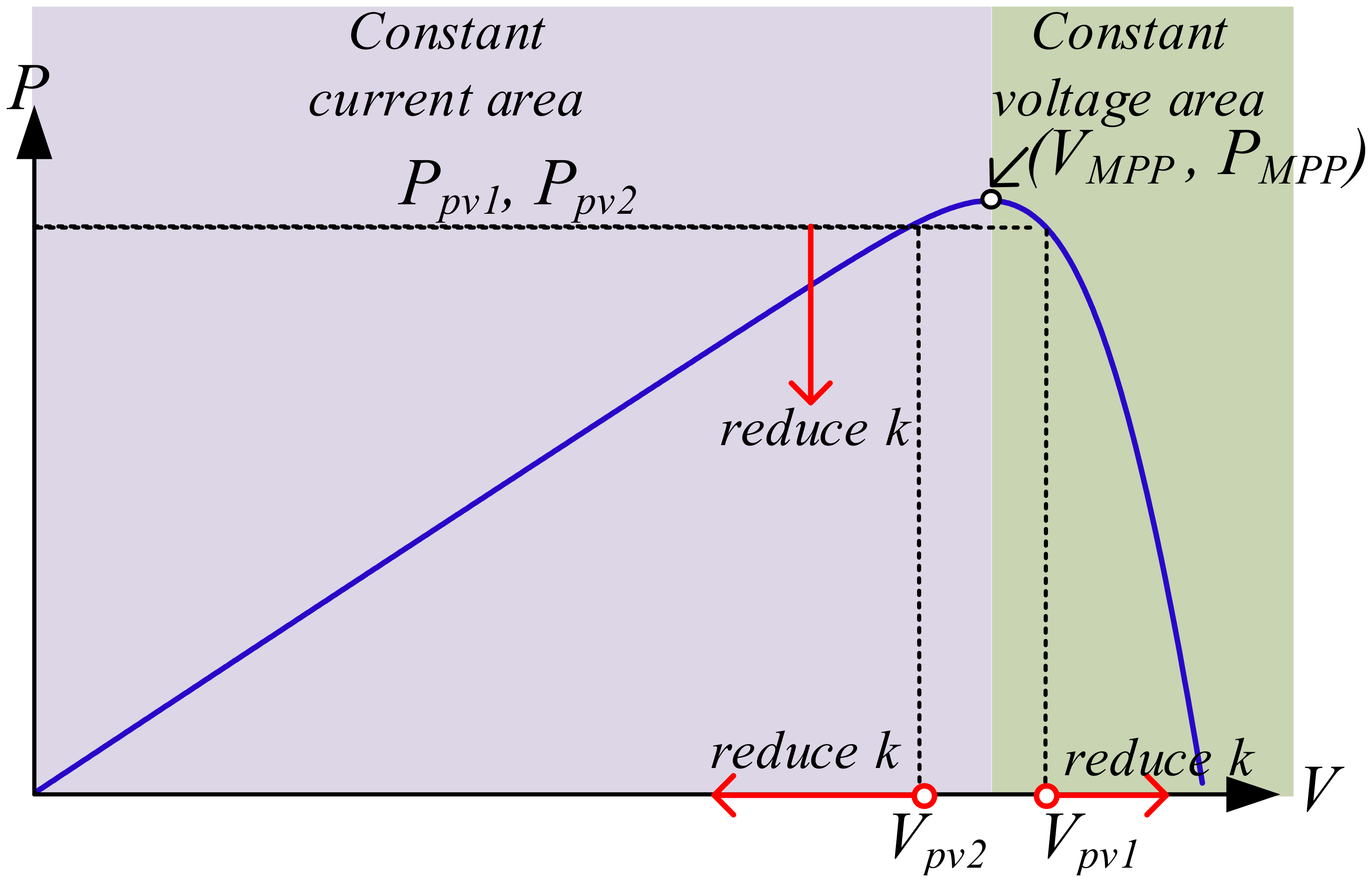
Figure 10.
MPPT assessment: (a) solar irradiance, (b) ZSI1′s exchanged active (P) and reactive (Q) powers with the grid, (c) ZSI2′s exchanged active and reactive powers with the grid.
Figure 10.
MPPT assessment: (a) solar irradiance, (b) ZSI1′s exchanged active (P) and reactive (Q) powers with the grid, (c) ZSI2′s exchanged active and reactive powers with the grid.

Figure 11.
Output of PV strings: (a) voltage of string 1, Vpv1, (b) current of string 1, ipv1, (c) power of string 1, Ppv1 = Vpv1 × ipv1, (d) voltage of string 2, Vpv2, (e) current of string 2, ipv2, (f) power of string 2, Ppv2 = Vpv2 × ipv2.
Figure 11.
Output of PV strings: (a) voltage of string 1, Vpv1, (b) current of string 1, ipv1, (c) power of string 1, Ppv1 = Vpv1 × ipv1, (d) voltage of string 2, Vpv2, (e) current of string 2, ipv2, (f) power of string 2, Ppv2 = Vpv2 × ipv2.

Figure 12.
(a) Grid voltage, Vg, (b) current injected to the grid by ZSI 1, i1, (c) current injected to the grid by ZSI 2, i2.
Figure 12.
(a) Grid voltage, Vg, (b) current injected to the grid by ZSI 1, i1, (c) current injected to the grid by ZSI 2, i2.
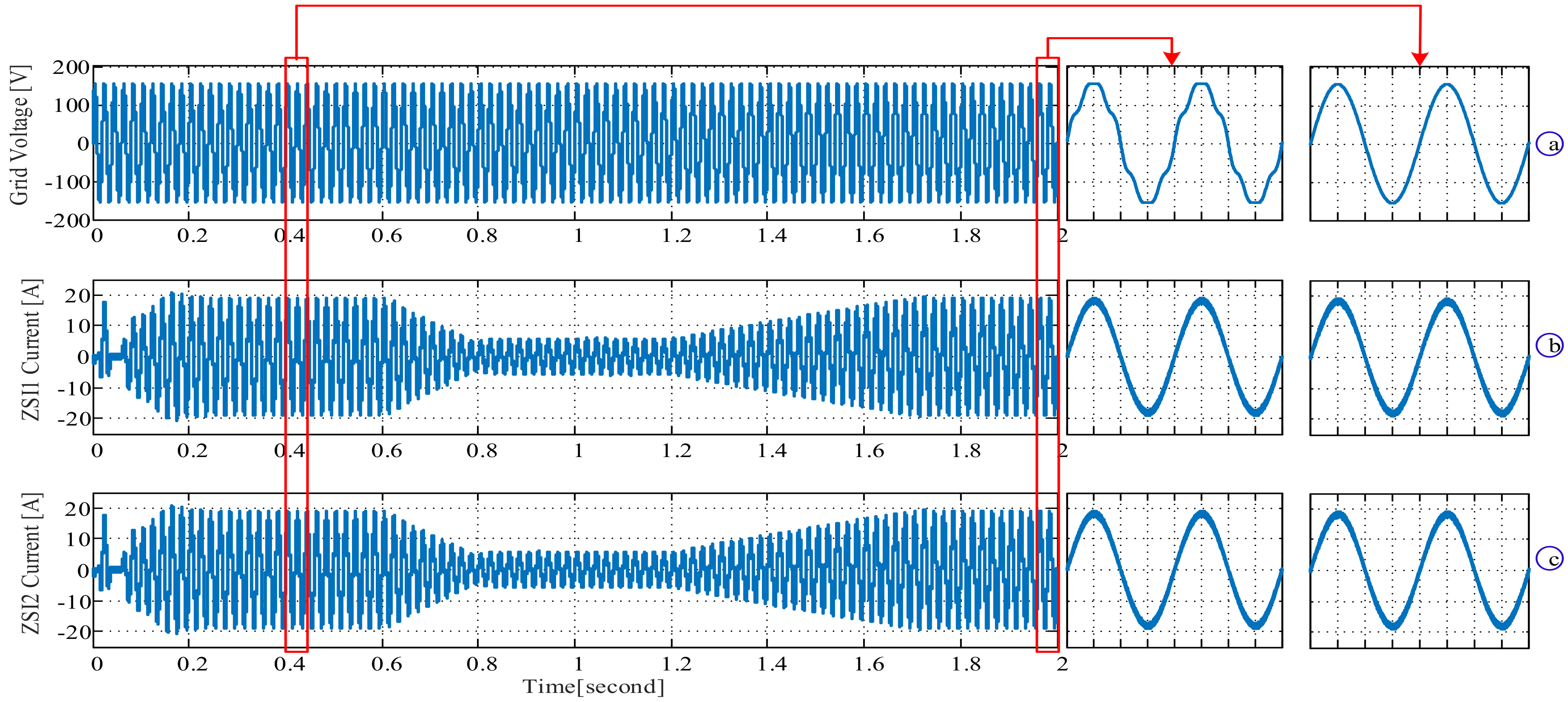
Figure 13.
Harmonic spectrum of the output current of ZSI 1, i1.
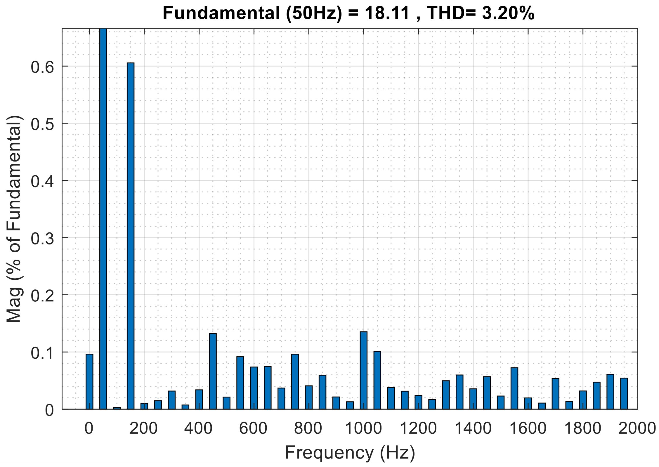
Figure 14.
(a) Capacitor voltage of ZSI1, Vc11, (b) DC link voltage of the ZSI1, Vc21, (c) capacitor voltage of ZSI1, uin1, (d) DC link voltage of ZSI2, uin2.
Figure 14.
(a) Capacitor voltage of ZSI1, Vc11, (b) DC link voltage of the ZSI1, Vc21, (c) capacitor voltage of ZSI1, uin1, (d) DC link voltage of ZSI2, uin2.
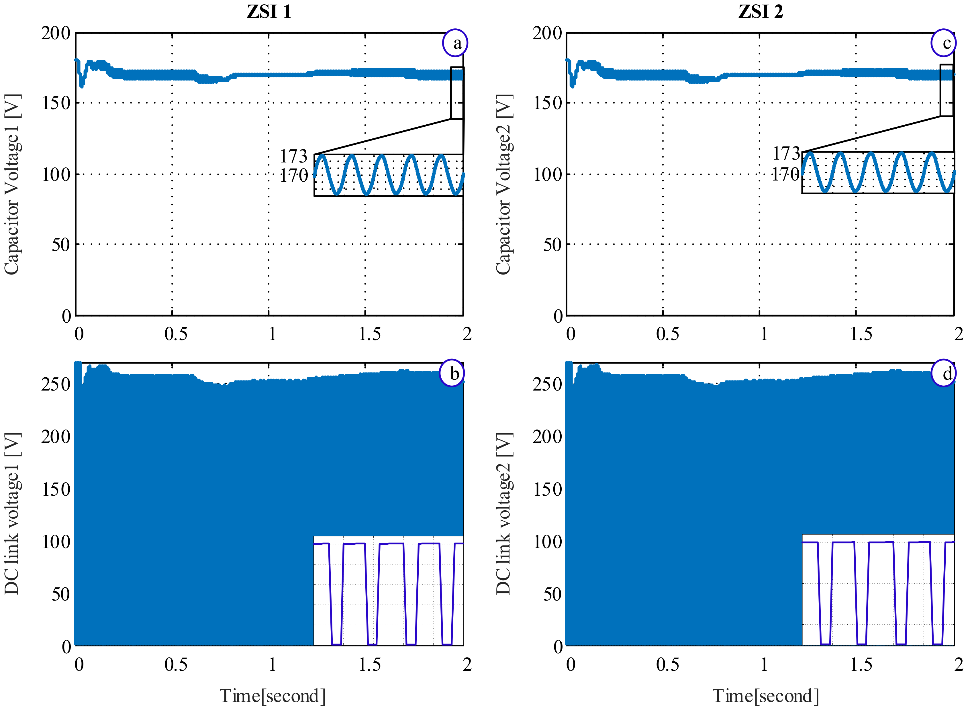
Figure 15.
Performance of eDS-MPPT for unequal solar irradiance (a) solar irradiances, (b) power of string 1, Ppv1, (c) power of string 2, Ppv2.
Figure 15.
Performance of eDS-MPPT for unequal solar irradiance (a) solar irradiances, (b) power of string 1, Ppv1, (c) power of string 2, Ppv2.


Table 1.
Parameters of the Z-source network.
| Parameter | Symbol | Value |
|---|---|---|
| Inductor of Z-source network | L | 2 mH |
| Capacitor of Z-source network | C | 2200 uF |
Table 2.
Parameters of each PV string in the nominal solar irradiance (1000 W/m2) [46].
Table 2.
Parameters of each PV string in the nominal solar irradiance (1000 W/m2) [46].
| Parameter | Symbol | Value |
|---|---|---|
| Current at maximum power | IMP | 15.22 A |
| Voltage at maximum power | VMP | 105.2 V |
| Maximum power | Pmax,e | 1600 W |
| Short circuit current | Isc | 16.42 A |
| Open circuit voltage | Voc | 131.6 V |
| Temperture coefficient of Voc | KV | −0.123 V/K |
| Temperture coefficient of Isc | KI | 0.0032 A/K |
Table 3.
Controllers parameters.
| Parameters | Symbol | Value | |
|---|---|---|---|
| Capacitor voltage controller | Proportional parameter | kpdc | 0.7 |
| Integral parameters | kidc | 20 | |
| Current controller | Proportional parameter | kp | 0.08 |
| Resonant parameter | ki | 150 | |
| eDS-MPPT tracker gain | parameter k | k | 0.95 |
Publisher’s Note: MDPI stays neutral with regard to jurisdictional claims in published maps and institutional affiliations. |
© 2020 by the authors. Licensee MDPI, Basel, Switzerland. This article is an open access article distributed under the terms and conditions of the Creative Commons Attribution (CC BY) license (http://creativecommons.org/licenses/by/4.0/).
Share and Cite
MDPI and ACS Style
Shahparasti, M.; Savaghebi, M.; Adabi, E.; Ebel, T. Dual-Input Photovoltaic System Based on Parallel Z-Source Inverters. Designs 2020, 4, 51. https://0-doi-org.brum.beds.ac.uk/10.3390/designs4040051
AMA Style
Shahparasti M, Savaghebi M, Adabi E, Ebel T. Dual-Input Photovoltaic System Based on Parallel Z-Source Inverters. Designs. 2020; 4(4):51. https://0-doi-org.brum.beds.ac.uk/10.3390/designs4040051
Chicago/Turabian StyleShahparasti, Mahdi, Mehdi Savaghebi, Ebrahim Adabi, and Thomas Ebel. 2020. "Dual-Input Photovoltaic System Based on Parallel Z-Source Inverters" Designs 4, no. 4: 51. https://0-doi-org.brum.beds.ac.uk/10.3390/designs4040051