Die Material Selection Criteria for Aluminum Hot Stamping


1
AZTERLAN, Basque Research and Technology Alliance (BRTA), Aliendalde Auzunea 6, 48200 Durango, Spain
2
BATZ, Torrea Auzoa 2, 48140 Igorre, Spain
*
Author to whom correspondence should be addressed.
J. Manuf. Mater. Process. 2021, 5(1), 15; https://0-doi-org.brum.beds.ac.uk/10.3390/jmmp5010015
Submission received: 29 December 2020
/
Revised: 25 January 2021
/
Accepted: 29 January 2021
/
Published: 2 February 2021
Abstract
:The aim of this work is to develop a die material selection criterion for aluminum hot stamping applications. The criterion has been based on the back-to-back comparison of a set of reciprocating friction and wear tests. Three representatives belonging to different stamping die material families have been selected for the study: a cold work steel, a hot work steel, and a cast iron. These tool materials have been combined with an exemplary member from two heat treatable aluminum families: 2XXX and 6XXX. Each die-material/aluminum–alloy combination has been tested at three temperatures: 40, 200, and 450 °C. The temperatures have been selected according to different stamping scenarios: long takt time press quenching, short takt time press quenching, and very short takt time hot forming without quenching, respectively. The results show that, among the three die material options available, the cold work steel turned out to be the most favorable option for high volume production and long takt time, the hot work steel fitted best for high volume production coupled with short takt time, and cast iron turned to outstand for short runs with prototype dies and for hot stamping without die quenching.
Keywords:
selection criterion; die material; aluminum alloy; hot stamping; tool steel; cast iron; friction; wear1. Introduction
Material selection is a factor of major influence on the profitability of hot stamping dies. It directly impacts die cost, new product development lead time, and productivity (takt time + die life). Three properties must be considered regarding the die material [1]: wear resistance, thermal conductivity, and toughness.
- Wear resistance is required to ensure the dies hold their shape within admissible tolerance limits during production. Hardness is often used in industrial practice for wear related material selection. Nevertheless, its correlation to wear resistance in hot stamping is not straightforward. Works studying tool wear for steel hot stamping show that tool steels with the same hardness levels being tested under the same setups may lead to significantly different wear rates [2]. This behavior is associated to microstructural and compositional differences between tool steels [3]. Furthermore, the stamping conditions can also significantly affect wear, as for example with the addition of lubricants [4]. Only dry contact is considered for this work, so that the developed material selection criterion cannot be extrapolated to lubricated hot stamping.
- High thermal conductivity is a specific requirement of hot stamping die materials, as this production process combines a hot forming operation and a heat treatment. The cooling rate of this heat treatment determines the mechanical properties of the formed part and has become an issue of interest both in steel [5,6,7,8] and aluminum [9,10] hot stamping. A high thermal conductivity tool material combined with a properly designed internal cooling channel system allows the right stabilization of die temperature [11] for the high production demands of the automotive industry.
- Toughness must also be considered to stand the high stress intensity factors that arise on cooling channels. Unless the die material is tough enough, these stress intensity factors have been known to cause die failures in service.
Hot work tool steels are the most appealing material family for hot stamping dies, as they offer the required high wear resistance, thermal conductivity, and toughness. In consequence, the automotive sector, which is the industrial application where hot stamping is most implanted, uses extensively hot work tool steels. Hot stamping die related friction and wear have been studied extensively employing hot work tool steels, with 1.2343 [12,13,14,15,16], 1.2344 [17,18,19,20,21,22,23], and 1.2367 [18,24] as the most frequent choices. Some have been also employed for aluminum coated steel hot stamping [20], together with proprietary steels such as Toolox® 44 from SSAB [21], QRO90® Supreme from Uddeholm [2,25], or W300® from Böhler [4].
Nevertheless, the use of hot work tool steels is not clearly stablished as the best option when alternative production scenarios allow enough time between press strokes for the die to be cooled by natural convection. No internal cooling would be necessary under these circumstances, making thermal conductivity and toughness less relevant on material selection criteria. This is the case of aluminum alloy hot stamping for aerospace industry, where the number of strokes the dies must last for is lower, and the production takt times are longer than in usual long run automotive mass production. Cooling channels would also be unnecessary when very short takt times are considered, such as in a transfer press lines if heat treatment is performed in a later operation. Materials with lower toughness and thermal conductivity than hot work tool steels become, as a result, candidates for aluminum hot stamping dies. Members of the cold work tool steel and pearlitic cast iron families, such as 1.2379, 1.2063 [17], GJS-700-3 ductile cast iron, and GJL-350 gray iron [26,27], fit into this description and have been studied in the literature related to aluminum hot stamping die friction and wear. They should thus be considered as options for die material selection when friction and wear behavior outweigh thermal conductivity and toughness.
When the literature is checked for aid in choosing a die material family for these alternative scenarios, the available variety of experimental approaches (number of combinations of test setup, testing parameters, and materials) is broad. The documentation that has been taken for reference in this paper shows the following range of possible test setups:
The test parameters employed with these setups have been found to be at different points within the following limits:
- Hot testing temperature ranging from room temperature (most works use it as reference) up to 500 °C [15,19,21]. It must be remarked here that hot strip drawing and top hat drawing tests, whose setup resembles most closely the industrial processing conditions, are performed with the aluminum being hot and the die being at a lower temperature. This approach simulates the extraction of the hot blank from the furnace and die refrigeration.
Finally, regarding the materials involved in the studies, the die materials choices that have been shown earlier are coupled with a variety of aluminum families:
Having the variety of combinations described above into account, it turns out that most of the die material comparisons that could be useful to develop die material selection criteria belong to individual papers and are performed with the same die material family (generally hot work tool steels [2,18]), with surface or manufacturing route modifications of a given material (e.g., thin coatings, nitriding, nitrocarburizing, additive vs. conventional manufacturing [13,15,18,21,26,27]) or, when a comparison between material families has been found (e.g., a hot and a cold work tool steel [17]), the comparison itself was not the aim of the paper. Thus, they are of little use for supporting the selection of a die material family among hot work tool steels, cold work tool steels, and cast irons, to manufacture aluminum hot stamping dies for non-mass production applications.
This paper contributes to amend this issue with a study for selection criterion development, which considers:
- a single experimental approach applied to the three tool material families and two relevant families of aluminum alloys; this experimental approach is based on tribological methods, more specifically reciprocating friction and wear tests, since thermal conductivity and toughness are less relevant when conventional hot stamping mass production is not concerned (assumptions per family are made in Table 1),
- different supply chain assumptions (cost and lead time assumptions are referred in Table 2),
- and industrial variables different from regular automotive high productivity scenarios (takt time and expected volume of production for the die).
Table 1 gathers the assumptions that have been made for the three die material families that will be considered for developing the selection criterion. These assumptions have been graded in terms of “low”, “medium”, and “high” to rank an average member of each family. This grading does not account for all the possible material choices within each family. The families can overlap their properties, since they have a broad variety of members. All the same, die cost and lead time can strongly vary depending on the manufacturing process and the complexity of the die. Thus, all exceptions arising from these facts have been simplified and/or left out of the scope of this work.
Table 2 gathers the scenarios that have been considered for material selection, where “low”, “medium”, and “high” production volumes are considered analogous to prototyping, aerospace, and automotive stamped part volumes, respectively. In terms of takt time, “short”, “regular”, and “long” correspond to “hot forming without quenching”, “hot forming and quenching with internal die cooling to keep the production pace”, and “hot forming and quenching cooling down the die without internal cooling”, respectively.
The hot work tool steel QRO90, the cold work tool steel 1.2379, and the GJS-700-2L cast iron are the three representants from the tool material families that have been selected for the study. QRO90 is widespread in industrial use for steel hot stamping and in regular service conditions offers a thermal conductivity of ≈33 W/m·K and a toughness of ≈15 J for a 10 × 10 mm·Kv impact specimen [28,29]. 1.2379 is a high performance cold working steel suitable for cutting operations thanks to its high wear resistance whose thermal conductivity is impeded by a high carbide density, with ≈20 W/m·K as reference value. Its toughness in terms of impact testing is <10 J and ≈28 MPa·m1/2 if measured as KIC [30]. GJS-700-2L is a pearlitic ductile cast iron grade, which has been developed specifically for the automotive sector and is widely used to manufacture tools for steel cold stamping. It shows an intermediate thermal conductivity between the other two options (≈31 W/m·K [31]) and a toughness of <10 J and ≈40 MPa·m1/2 [32] for impact testing and KIC, respectively. The thermal conductivity values were supplied for reference by steelmakers for the tool steels. Reference impact test values from 1.2379 and GJS-700-2L belong to lab records from the authors, which were performed with a 300 J Charpy hammer and 10 × 10 × 55 mm notched specimens according the UNE-EN ISO 148-1 standard.
Raw material cost-wise, QRO90 is the most expensive in terms of alloying, mainly due to the Mo and V contents. It is followed in cost by 1.2379, which shows a high Cr amount, and GJS-700-2L, whose alloying is inexpensive compared to both steels [33]. Productive process cost wise, cast iron is the cheapest choice, since it involves casting and little postprocessing in general stress relief heat treatment, machining, and surface hardening on occasion. Regarding the hot and cold work tool steels, QRO90 is produced using electro slag remelting (ESR) while 1.2379 can be also acquired saving ESR costs at sacrificing toughness. Furthermore, the composition of 1.2379 is used in near net shape casting in stamping die production, taking the steel number 1.2382 in this case. This leads to further reductions in die cost at the expense, again, of toughness.
In terms of lead time, wrought steels are more readily available than as-cast condition dies, due to the time consumed by foundry model making and casting. In this sense, as QRO90 is always supplied in wrought condition, it has been considered the fastest supply. Since 1.2379 can be acquired through both rolling/forging and casting, it has been considered an intermediate.
Therefore, the chosen representatives satisfy the assumptions made in Table 1 in the conditions described above. As stated in the introduction, it must be remarked that exceptions to the scenarios exist and have not been considered in this work (e.g., raw material restrictions due to geopolitical changes, logistics due the lack of availability of a given material/process in geographical area).
The aluminum alloys selected for the study belong to 2XXX and 6XXX families, as they have been found most often in the references that have been checked for this work. The specific choices have been 2011 and 6026 alloys in T3 and T9 delivery condition, respectively. Both alloys are used as substitutes of each other in applications in which further machining is required after hot forming, as they are considered free cutting alloys. Regarding the physical properties, material manufacturers specify that their thermal conductivity is ≈150 W/m·K, and their ultimate tensile strength goes up to 370 MPa while exceeding 8% elongation for both aluminum grades in the T6 service condition that would correspond to the final strength of hot stamped aluminum parts.
2. Materials and Methods
2.1. Die Materials
The specific die material batches employed in this work were extracted from actual industrial stamping dies. Their chemical composition analysis (provided by material suppliers) and the hardness are given in Table 3.
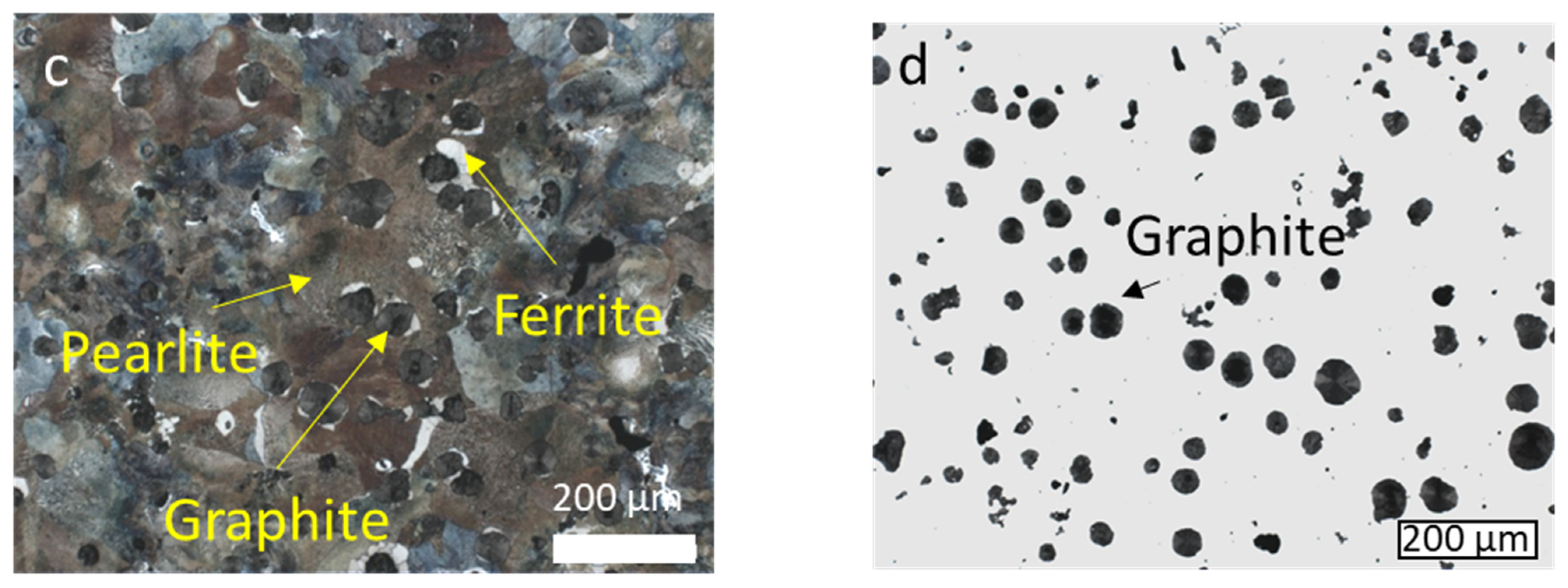
The microstructure of the three tool material samples, shown in Figure 1, has been inspected to ensure that they presented no structural deviation. All the micrographs fitted with regular production conditions: the cold work tool steel 1.2379 was composed by tempered martensite and carbides (Figure 1a). The hot work steel QRO90 presented a microstructure of tempered martensite (Figure 1b) and the cast iron was constituted by a matrix of pearlite, with ferrite quantities around 5–10% (Figure 1c). The graphitic density was 100 nodules/mm2 and the spheroidization of the graphite was in the range between 85% and 90%, with an average diameter of 50 μm (Figure 1d).
Flat disks with dimensions Ø24 × 7.9 mm as in [2,3] have been machined from tool material samples for wear testing. All the disks have been conditioned by sanding and subsequent polishing to achieve a surface roughness <0.3 µm Ra in the testing surface. This fact was verified by measuring roughness in all samples with a Taylor Hobson Limited Surtronic 3 equipment.
2.2. Pin Materials
The aluminum alloy samples have been acquired in extruded Ø20 mm for the 2011 and drawn Ø12 mm bar formats for 6026 that were machined for the study according to the flat end Ø2 mm pin geometry reported in earlier works from the authors [2,3].
To ensure the supply was correct, the actual chemical composition of the aluminum alloys has been checked (Table 4), where it is shown that the samples satisfied the expected specifications. As an unusual feature for hot stamping, it can be observed that both samples show similar amounts of alloying elements targeted to free cutting, Pb + Bi = 0.79% for the 2011 and Bi = 0.93% for the 6026.
The agreement of the mechanical properties of the samples of 2011 and 6026 with the delivery conditions mentioned above has been verified by tensile testing according UNE-EN ISO 6892-1 standard (Table 5).
The microstructure of both aluminums used for the tests has also been checked. The micrographs are shown in Figure 2. It can be observed that the microstructure of the 2011 samples is composed by an α aluminum matrix that contains CuAl2, intermetallic precipitates bearing Fe, Mn, and Si (Figure 2a) and a distribution of Pb and Bi for free cutting. The 6026 samples showed a matrix of α aluminum with a dispersion of Fe, Mn, and Si bearing precipitates and a distribution of Bi for free cutting (Figure 2b). The identification of the phases was initially performed by light optical microscopy (LOM) and confirmed later by scanning electron microscopy (SEM) and electron dispersive x-ray analysis (EDX) (Figure 2c,d).
2.3. Experimental Method
The study of the friction and wear behavior has been carried out with a reciprocating sliding friction and wear tester (SRV) model 8.110. The SRV device is provided with an electromagnetic drive, which allows the upper specimens (2011 and 6026 pins) to oscillate under normal load against a stationary lower test specimen (the three tool materials), as shown in Figure 3. The SRV tribometer has a servo motor, which is used to apply the selected normal load. The conditioning of the disks at the selected temperature was done by means of a heater placed in the lower test specimen holder. During each test, the applied load, temperature, stroke length, and frequency of the oscillatory movement were controlled and monitored with the computerized data acquisition and control system of the device.
The test parameters (Table 6) have been based on an industrial hot stamping contact condition scenario. The rationale behind these parameters replicates previous is as follows:
- The stroke length has been selected so that the total covered length was at least three times the pin diameter (4 mm stroke + 2 mm pin diameter = 6 mm of covered surface).
- The frequency has been chosen to resemble the average sliding speed between a die radius and a hot stamped sheet in a contact radius of an omega profile of a servo-mechanical press 100 mm/s. Although it is several orders of magnitude over the value employed in some references [26,27], this value fits with most works in the checked literature 25–100 mm/s [2,3,15,16,20,21,25].
- The temperatures of 40, 200, and 450 °C have been chosen to be representative of the die temperature for a prototyping low productivity scenario, the die temperature for an industrial high productivity scenario, and a condition of high production rate (short takt time) hot stamping without quenching, respectively. Furthermore, it must be considered that the COF is related to microhardness and microstructure in heat treatable aluminum alloys, and three clearly distinct conditions have been forced in the tests: at 40 °C, the materials are in T6 condition, which means that the microstructure is composed by an alpha aluminum matrix and a collection of coherent hardening precipitates. When the tests are set at 200 °C, a progressive over-ageing is provoked in the aluminum. In this process, the CuAl2 (for 2011) and Mg2Si (for 6026) precipitates grow, and the matrix softens not only due to temperature increase, but also due to coarsening of the hardening precipitates. Finally, when the tests are performed at 450 °C a more complex scenario arises: a fraction of the precipitates starts dissolving back in the matrix, while the rest grows coarser, free machining additions melt (Pb and Bi), and the matrix keeps softening because of temperature increase.
Before testing, all the disks and pins were cleaned in an ultrasonic bath where the samples and adapters were immersed first in ether for 5 min and then 5 min in acetone. Afterwards, the samples and adapters were then wiped dry and placed in a desiccator to completely remove moisture. Right before starting each test, the disks and pins were weighed. The test started by heating the disks to the desired temperature with a programmed ramp up time of 5 min, followed by a dwell time of 5 min at the set point temperature. During the warmup process, the pins were kept in contact with the disks. The tests started after this period and lasted 15 min. During each test, the evolution of the coefficient of friction (COF) was recorded as at a rate of 1 Hz. After finishing each test, the samples were cleaned in an ultrasonic bath, for 5 min in ether plus 5 min more in acetone.
Both pins and disks were weighted after testing. Since the adhesion of aluminum to the disks was not removed by the post-test cleaning process, weight-based wear rates have been calculated only for the pins. Instead, a Nikon Eclipse ME600 confocal microscope was used to assess wear and adhesion on the disks employing wear track cross sections. A minimum of two repeats was performed for each temperature, tool material, and aluminum alloy combination.
3. Results and Discussion
The discussions in this section refers to values obtained by other authors, which must be taken only for reference and interpreted considering that different tribopairs tested under different conditions were used.
3.1. Coefficient of Friction
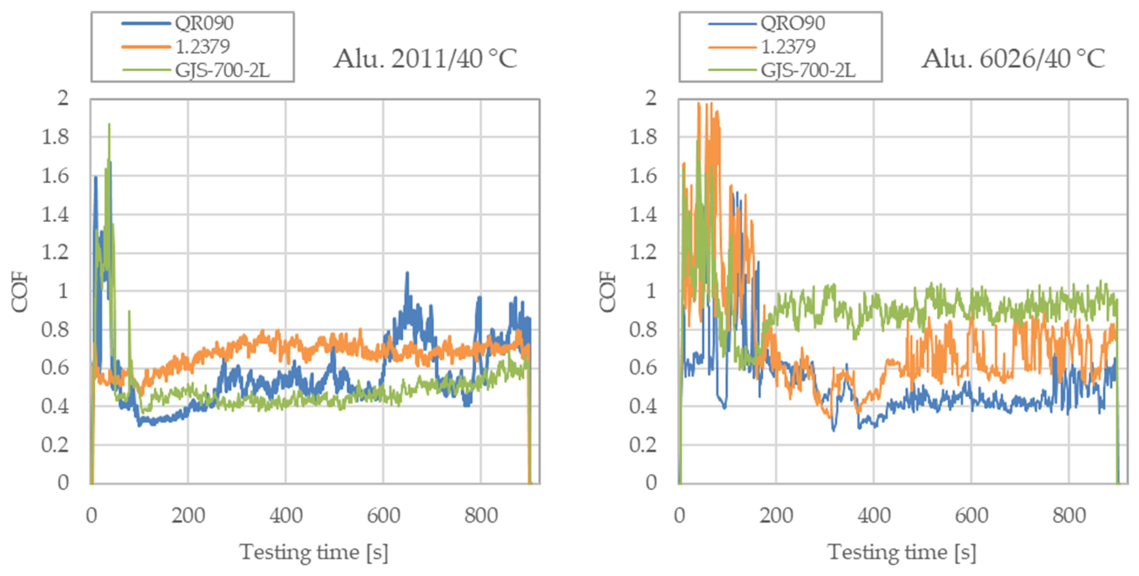
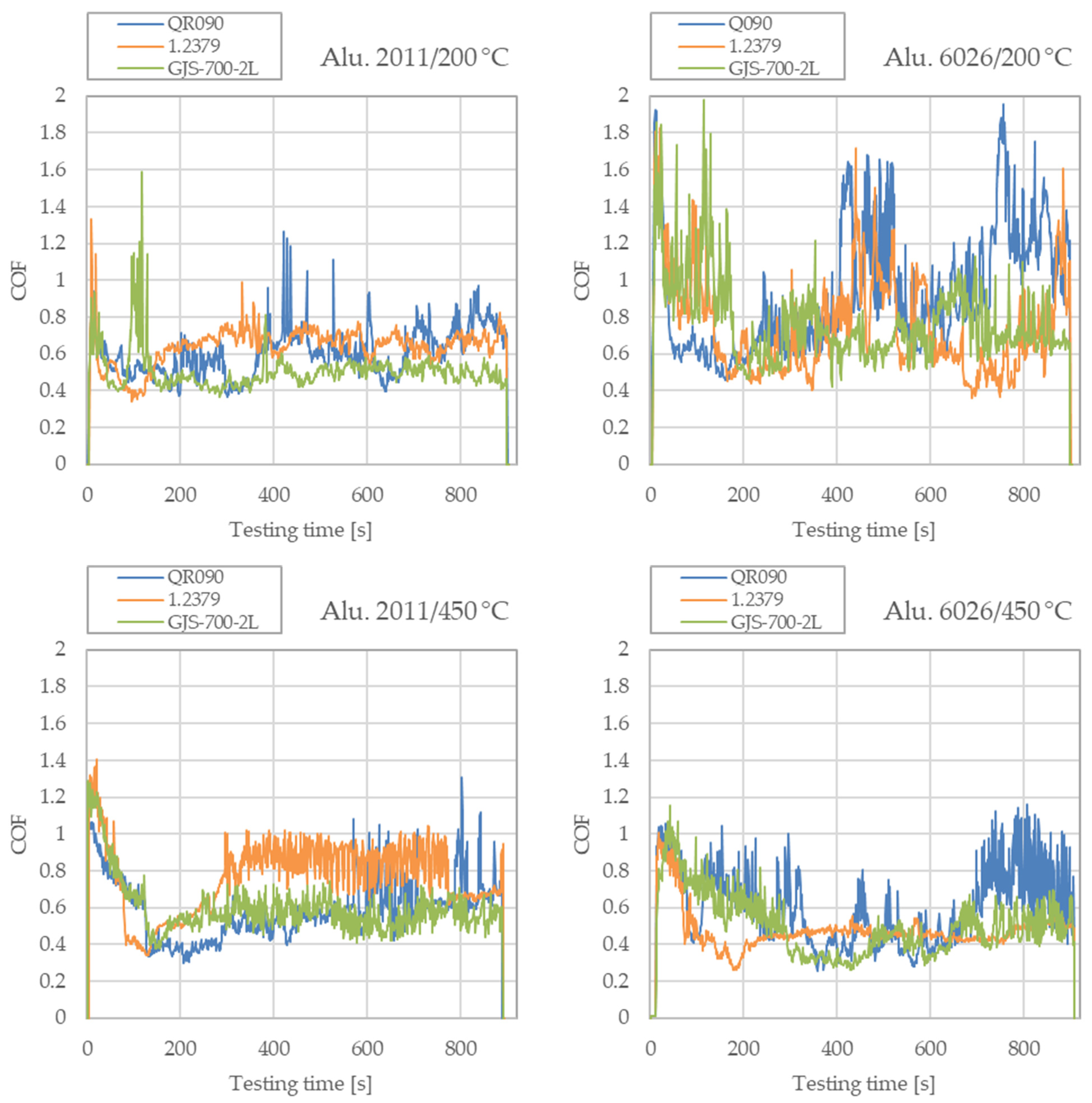
The COF is a relevant characteristic for all stamping processes as it modifies the contact force distribution during the press stroke. Figure 4 gathers the COF data corresponding to one of the repeats for each test condition to assess how each tool material behaves in terms of this parameter.
The curves show that in most cases, the COF tends to stabilize after an initial transitory of approximately 200 s and, once stabilized, the COF is in the range between 0.5 and 0.9. Similar results were observed by other authors in similar tests involving H13 hot work steel and 2017 aluminum [20].
- Results at room temperature: at room temperature, both tool steels showed a more consistent average COF, close to 0.5 for the hot work steel and close to 0.65 for the cold work steel, independently of the aluminum series tested. The cast iron, on the other hand, showed a higher dependence on the aluminum family at room temperature: COFs 0.4 and 0.9 have been found when using 2011 and 6026, respectively. It is worth noting that the GJS-700-2 shows a much steadier COF reading, which is related to an abrasive wear mechanism [34] for both aluminum alloy pins, while cold work tool steel shows this behavior only for the 2011 alloy.
- Results at 200 °C: when comparing room temperature COF with the COF at 200 °C, no major differences have been found when using 2011, with the values converging to the range 0.50–0.70. On the other hand, when 6026 has been employed the COF showed a higher variation, no matter the tool material involved (from 0.40 to 1.40): the average COF increased up to 63% for the hot work tool steel and up to 16% for the cold work tool steel, while the COF against cast iron decreased by 15%. Tests in [16] with a hot work tool steel (H11) and a 7XXX series aluminum (7075) were performed at the same temperature under similar conditions. In this case, COF values ranged from 0.40 to 0.60, which also is observed in Figure 4 for the 2XXX alloy. Other works such as [19] suggest that COFs over 2.0 for higher contact pressures (600 MPa) should be expected for a hot work steel (H13) and 6XXX (6060) tribopair. No information has been found in the literature to assess whether the COF increase in [19] is due to the use of 6XXX in the tribopair, which would fit with the Figure 4, or due to the high pressure. The high variability of the COF reading for the 6026 alloy indicates that stick–slip behavior is governing the contact, thus indicating an abrasive wear mechanism.
- Results at 450 °C: all the tool materials tend to converge in time to a COF close to 0.55 both when 2011 and 6026 are used. Results from ball-on-disk and hot strip drawing tests performed at the same temperature [14,16], using a hot work tool steel (H11) and 7XXX series aluminums (7475 and 7075) in T6 condition suggest that higher COF values (from 1.2 to 1.75) should be expected. The tests with 7475 were performed at higher pressures (120 MPa), while the tests with 7075 were performed at pressures close to the 10 MPa employed in this work, but with a lubricant. It is noticeable that the exposure time to 450 °C for the specimens giving a COF of 1.2 was rather short (10 s for [16]), meaning that the T6 condition was not degraded during the test. On the other hand, the specimen results in Figure 4 correspond to dwelling plus sliding times up to 20 min, which would lead the aluminum progressively closer to a T4 condition, which was also tested in [16] and for which the COF dropped to 0.4 for [16]. Observing Figure 4, it fits that during the first minutes of the tests at 450 °C the pins worked in the T6 condition giving COFs close to 1.0–1.2 as in the T6 specimens from [16], while as the test progressed, the hardening precipitates of the aluminum progressively dissolved into a T4-like condition, like the T4 specimens from [16]. Thus, no major differences in the result would be expected if 7XXX aluminum series would have been used to build Figure 4.
There is no information in [14] regarding the heat treatment condition of the aluminum that might help clarifying if the COF peak to 1.75 is due to the working pressure or the thermal history of the aluminum sample that was employed.
In terms of the COF reading variability, the hot work tool steel shows the highest noise, which is related to a higher adhesion of the pin to the disk. This fact is later confirmed in the cross-section measurements of these disks.
3.2. Tool Material Wear
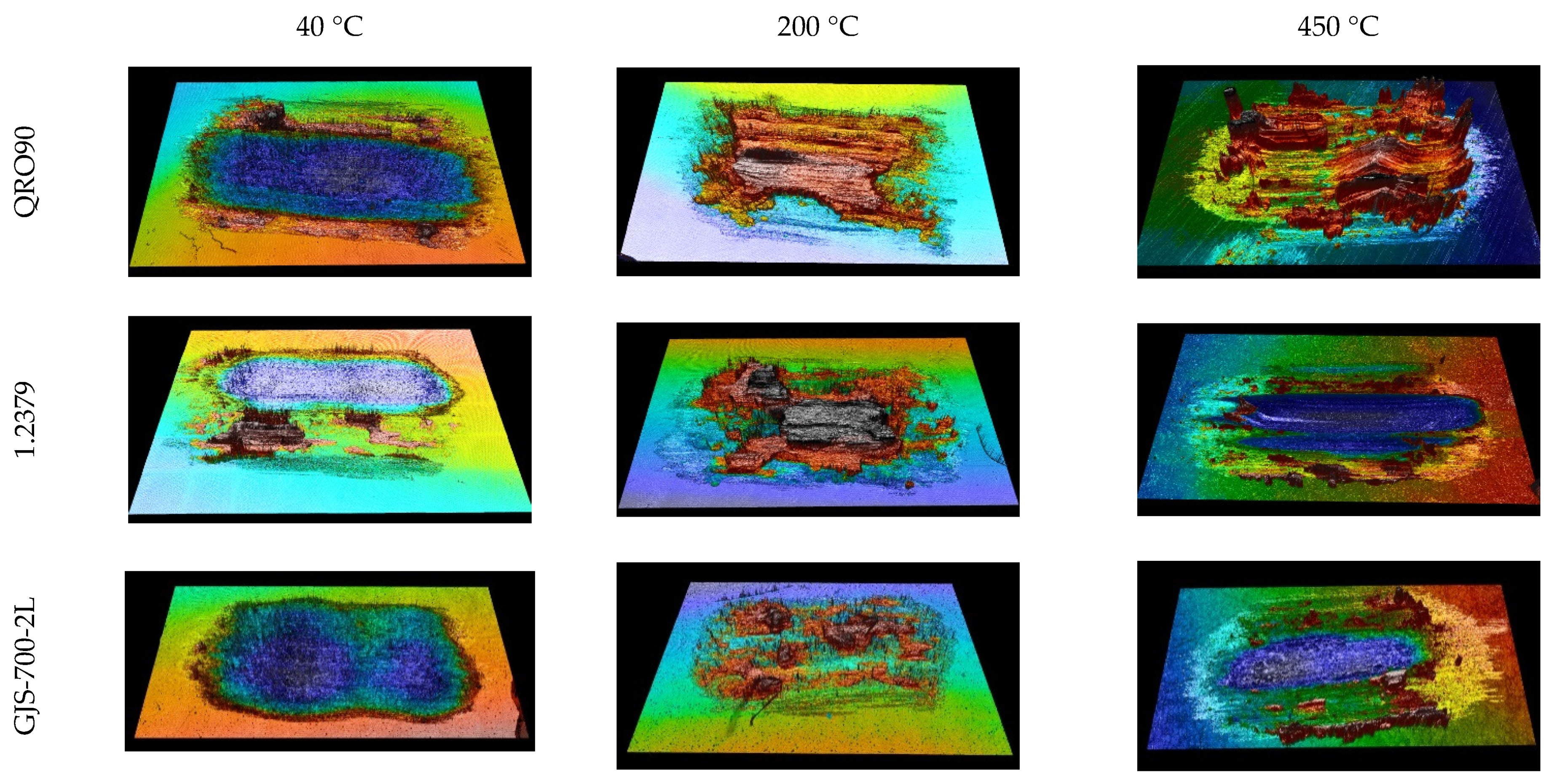
As was pointed out in the Materials and Methods section, the usual weight loss procedures were not applicable to assess the wear of the disks due to the presence of strongly adhered aluminum deposits. Thus, after each test, the profile of the contact path in the disks was characterized with a Nikon Eclipse ME600 confocal microscope. Figure 5 and Figure 6 show the wear tracks under confocal microscopy for the purpose of showing the overall look of the track.
Starting with Figure 5, corresponding to the 2011 pins, it can be seen that wear tracks are mainly grooves with minor adhesion for the tests at 40 °C. The column corresponding to 200 °C shows an increased adhesion compared to 40 °C tests, especially for the hot work tool steel. This fits with an increased tendency to adhesion with temperature, promoting galling. Finally, the test surfaces at 450 °C look similar for the three die materials, with the exception of a higher amount of debris in the track border for the hot work tool steel and the cast iron. This points to the shear stresses and wiping the adhered aluminum debris out of the test track.
It is noticeable that when using 2011 as pin material, the cold work tool steel is the option showing the lowest galling at all temperatures, and hot work tool steel suffered the highest galling on average.
Regarding Figure 6, corresponding to alloy 6026, it shows a pattern similar to 2011 at 40 °C, but a much more stickier behavior at 200 °C. Galling is observed on all die materials tested at this temperature, which is different from what is observed when using 2011 as pin material. This observation links with the differences observed in the COF when using 2011 and 6026 at 200 °C: the higher COF oscillations for 6026 match with a higher adhesion and stick–slip behavior. Regarding the tests at 450 °C, abrasive wear governs the response of cast iron and cold work steel, while severe adhesion is observed in the hot work tool steel.
It is noticeable that when using 6026 as pin material the hot work tool steel suffers galling both at 200 and 450 °C.
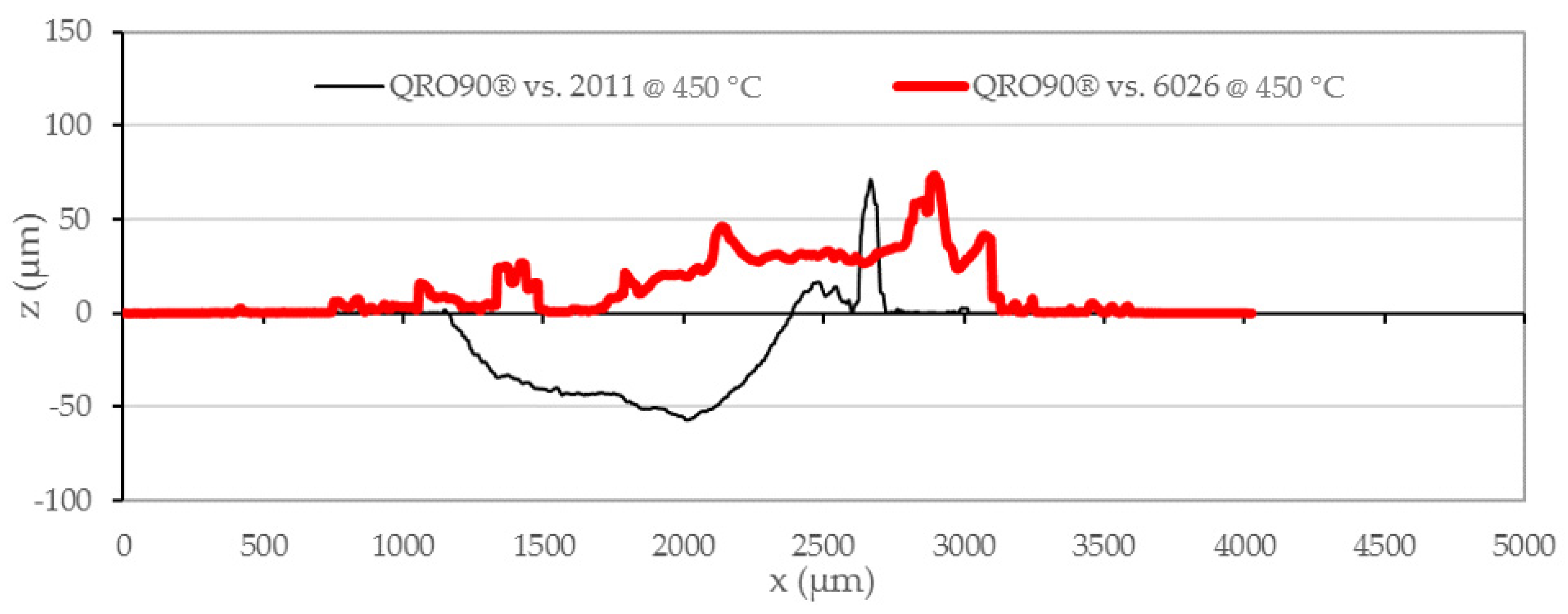
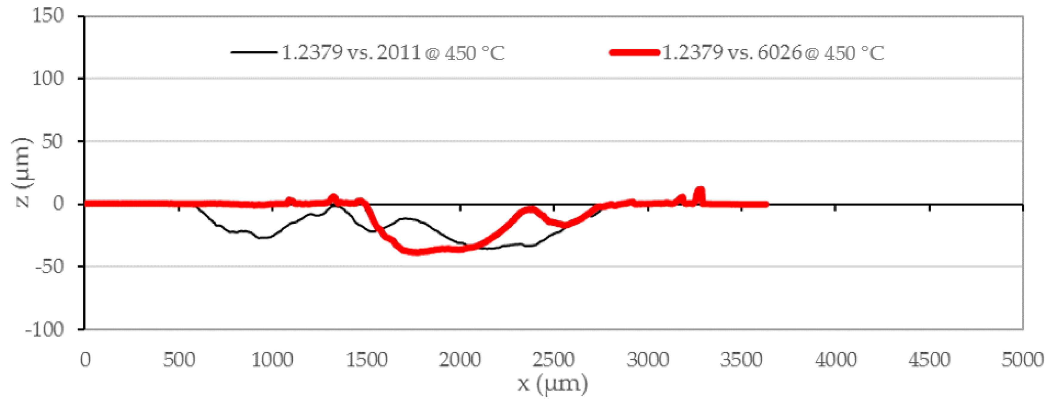
Figure 7, Figure 8, Figure 9, Figure 10, Figure 11, Figure 12 and Figure 13 gather a selection of these vertical cross sections, performed perpendicularly to the pin sliding direction and positioned coinciding with the middle of the pin stroke. The vertical axis shows the height (z) and the horizontal axis shows the width (x). The profile comparisons have been kept one-to-one for clarity. The sections were performed by means of confocal microscopy right in the center line of the stroke, perpendicular to the stroke direction. The position of the measuring line has been selected as it is the point submitted to highest demand in term of sliding speed.
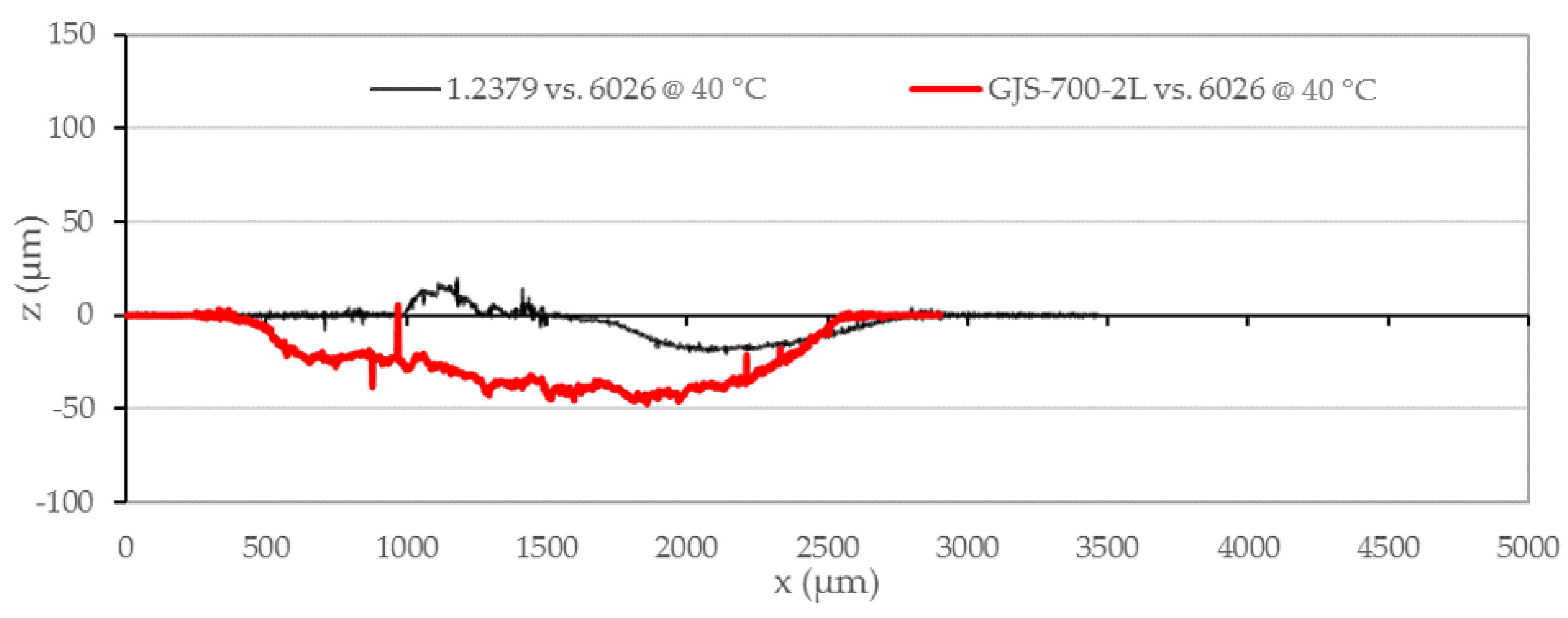
In all wear tests carried out at 40 °C, regardless of the material used in the disk or the pin, the abrasive wear dominated over galling, without any major adhesion protruding over the original disk surface. This fits with the observation from [16] that fixes the galling beginning at 350 °C. Tool steels showed a similar wear, which was significantly lower than for cast iron samples. Figure 7 compares the wear track at room temperature for 1.2379 and GJS-700-2L sliding against 6026. It can be observed that the cold work tool steel shows nearly no wear, while the groove for the cast iron reaches nearly a depth of 50 microns.
In the profiles of Figure 8, it can be observed that the disk that was tested with a 2011 pin shows a deposition protruding from the middle of the wear groove, while the disk tested with a 6026 pin shows a continuous groove without such adhesions.
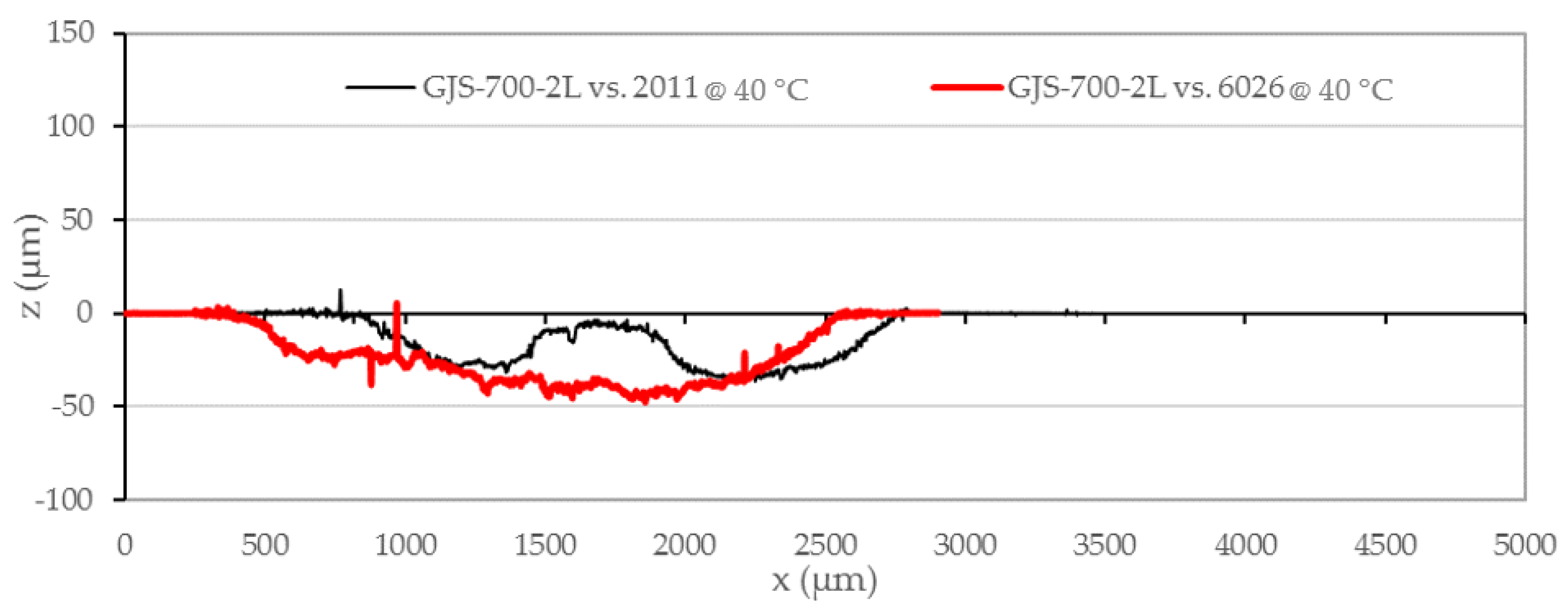
Figure 8 compares the wear performance the cast iron sliding against 6026 and 2011. There is a similar wear depth in both cases, meaning that the contribution of the type of aluminum as not significant.
Regarding the profiles of the tests carried out at 200 °C, wear is the governing mechanism when 2011 pins are used, no matter which tool material is employed. The same happens for GJS-700-2L disks, no matter which aluminum alloy is employed. Nevertheless, galling is observed when 6026 slides at 200 °C against tool steels.
These behaviors are shown in Figure 9 and Figure 10. Starting with Figure 9, when cast iron was used, tests with both 2011 and 6026 led to very low adhesion.
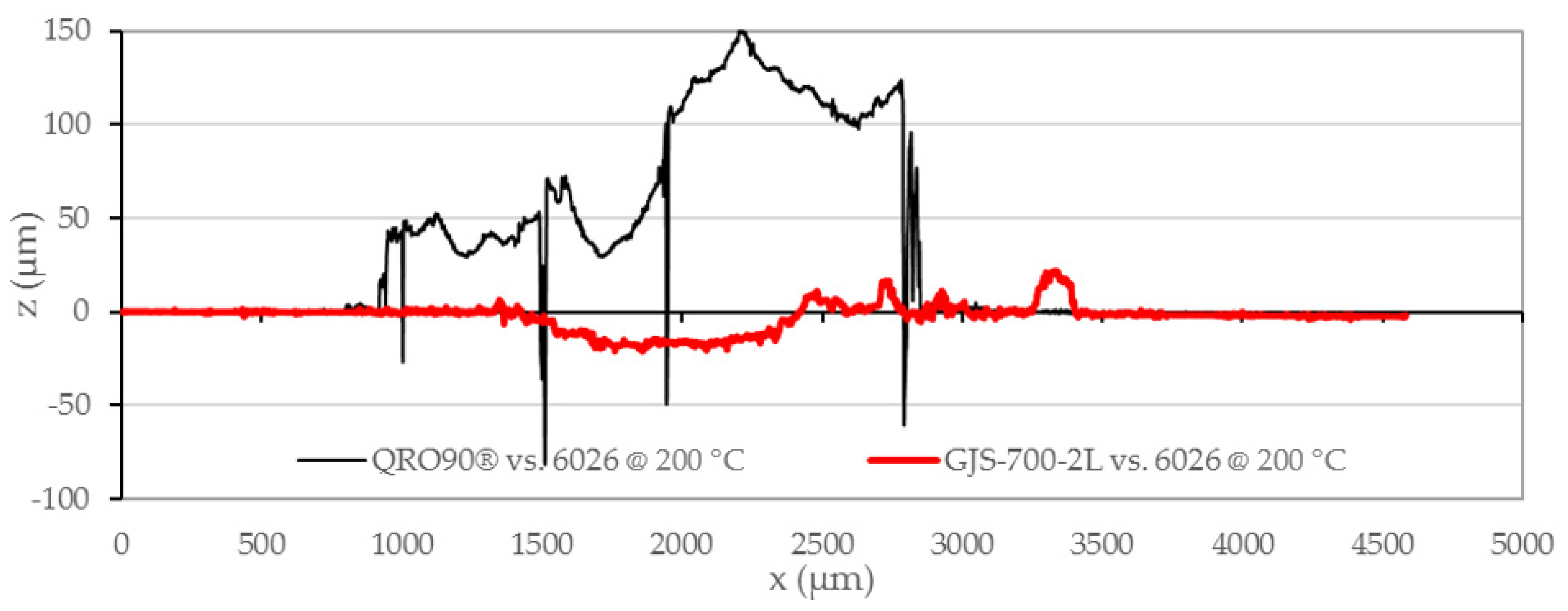
On the other hand, severe galling was found in the tests on tool steels against 6026 pins at 200 °C but not in cast iron. As proposed above, this observation points to a contribution from stick–slip phenomena to the increase in the average COF for the tests performed with 6026 at 200 °C. In Figure 10, it is obvious that cast iron is advantageous in terms of adhesion reduction. This advantage is understood to be caused by the presence of graphite in the microstructure, which is a common die lubricant in aluminum forging. Nevertheless, these lubricants are normally applied as an aqueous suspension of graphite powder, not as a set of microscopic nodules trapped in the die matrix. This means that, despite the fact that the low adhesion of aluminum to graphite is applied in regular industrial processes, it does not necessarily mean this function is fully transferred to the nodules in cast iron dies.
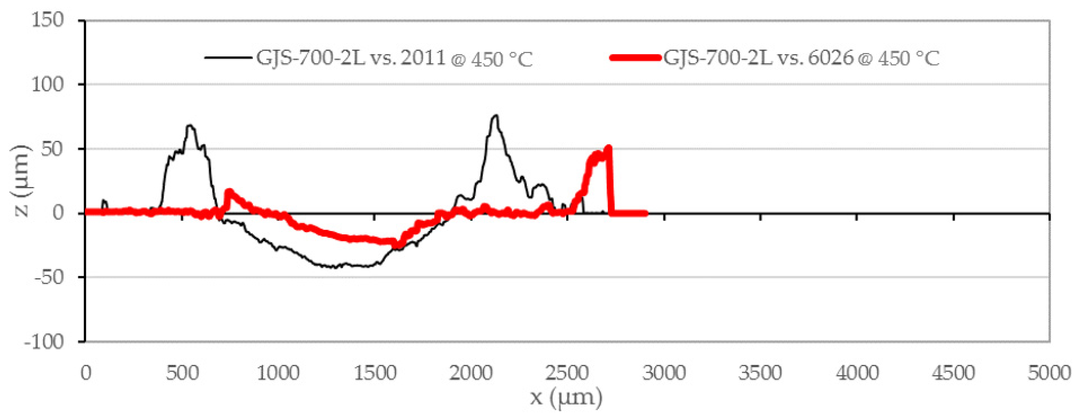
At 450 °C, cast iron behaves like it does at 200 °C, no matter the alloy used as pin, and the profiles differ from the tracks at 200 °C in a slightly higher material build up at the track sides. Figure 11 shows how the wear track depth in cast iron is close to 50 microns, as in Figure 8 and Figure 9. Thus, the wear track depth in GJS-700-2L showed little dependence on the working temperature and the aluminum alloy type. This means that creep, which has been reported in aluminum at stress levels that could have been present in the tests at 450 °C [35,36], has not been a major factor to be accounted for.
4. Conclusions
The conclusions are in summary:
- After the initial 400 s of the test, average friction coefficients are in the range between 0.4 and 0.9 for the three die material options in most cases. Hot work tool steel showed the most acute COF oscillation, what indicates it is more prone to adhesive wear.
- The 6026 alloy is more adhesive than the 2011, especially at 200 °C. This is proposed to be related to the combined effect of Mg2Si coarsening and aluminum matrix softening, which should then be stronger than for CuAl2 precipitates.
- The tested hot work tool steel has shown the worst performance in terms of adhesion not only in the COF graphs but also in confocal microcopy inspection, especially when a 6XXX aluminum has been used.
- Cast iron showed the lowest level of adhesion against both aluminum alloys at the most usual die temperature in press quenching technologies (200 °C).
- Under extreme conditions, such as the test at 450 °C, the three die materials showed a very similar behavior, with the hot work tool steel being more strongly affected by galling with 6026. Thus, cost would be the driving element for material selection leading to cast iron as the choice for very short takt time scenarios where die temperature is the highest.
Taking all the factors above into account, GJS-700-2L is considered the proper choice for short run prototype making dies in aluminium hot stamping if the lead time is not a limiting factor (Table 7): although it shows higher wear than the tool steels at the typical hot stamping die temperature, the galling on the tool steels modifies the tool surface geometry further than the wear and would require cleaning operations during stamped prototype production.
Author Contributions
Conceptualization: M.M. and G.A.; methodology: M.M. and G.A.; validation: I.A. and G.A., formal analysis: M.M.; investigation: M.M. and G.A.; resources: M.M. and I.A.; writing—original draft preparation: M.M.; writing—review and editing: G.A.; visualization: G.A.; supervision: G.A. and I.A.; project administration: I.A.; funding acquisition: G.A. and I.A. All authors have read and agreed to the published version of the manuscript.
Funding
The authors gratefully acknowledge the funding provided by to Rib-On project that has received funding from the Clean Sky 2 Joint Undertaking under the European Union’s Horizon 2020 research and innovation program under grant agreement No. 755493.
Data Availability Statement
The data presented in this study are available on request from the corresponding author.
Conflicts of Interest
The authors declare no conflict of interest. The funders had no role in the design of the study; in the collection, analyses, or interpretation of data; in the writing of the manuscript; or in the decision to publish the results.
References
- Chantzis, D.; Liu, X.; Politis, D.J.; El Fakir, O.; Chua, T.Y.; Shi, Z.; Wang, L. Review on additive manufacturing of tooling for hot stamping. Int. J. Adv. Manuf. Technol. 2020, 109, 87–107. [Google Scholar] [CrossRef]
- Muro, M.; Artola, G.; Gorriño, A.; Angulo, C. Wear and friction evaluation of different tool steels for hot stamping. Adv. Mater. Sci. Eng. 2018, 2018, 3296398. [Google Scholar] [CrossRef] [Green Version]
- Muro, M.; Artola, G.; Leunda, J.; Soriano, C.; Angulo, C. Compositional modification of tool steel to improve its wear resistance. Met. Mater. Trans. A 2019, 50, 3912–3921. [Google Scholar] [CrossRef]
- Ghiotti, A.; Bruschi, S.; Medea, F. Wear onset in hot stamping of aluminium alloy sheets. Wear 2017, 376–377, 484–495. [Google Scholar] [CrossRef]
- Fernández, B.; González, B.; Artola, G.; López de Lacalle, N.; Angulo, C. A quick cycle time sensitivity analysis of boron steel in hot stamping. Metals 2019, 9, 235. [Google Scholar] [CrossRef] [Green Version]
- Muro, M.; Artola, G.; Gorriño, A.; Angulo, C. Effect of the Martensitic Transformation on the Stamping Force and Cycle Time of Hot Stamping Parts. Metals 2018, 8, 385. [Google Scholar] [CrossRef] [Green Version]
- Mendiguren, J.; Ortubay, R.; Saenz de Argandoña, E.; Galdos, L. Experimental characterization of the heat transfer coefficient under different close loop controlled pressures and die temperatures. Appl. Therm. Eng. 2016, 99, 813–824. [Google Scholar] [CrossRef]
- Cortina, M.; Arrizubieta, J.I.; Calleja, A.; Ukar, E.; Alberdi, A. Case study to illustrate the potential of conformal cooling channels for hot stamping dies manufactured using hybrid process of laser metal deposition (LMD) and milling. Metals 2018, 8, 102. [Google Scholar] [CrossRef] [Green Version]
- Lui, X.; El Fakir, O.; Zheng, Y.; Gharbi, M.; Wang, L. Effect of tool coating on the interfacial heat transfer coefficient in hot stamping of aluminium alloys under variable contact pressure conditions. Int. J. Heat Mass Transf. 2019, 137, 74–83. [Google Scholar] [CrossRef]
- Baghbane, A.; Eivani, A.; Hasheminiasari, M.; Park, N.; Jafarian, H. Application of hot forming cold die quenching for facilitating equal channel angular pressing of AA2024 aluminium alloy. J. Alloys Compd. 2019, 791, 265–277. [Google Scholar] [CrossRef]
- Zheng, K.; Lee, J.; Xiao, W.; Wang, B.; Lin, J. Experimental investigation of the in-die quenching efficiency and die surface temperature of stamping aluminium alloys. Metals 2018, 8, 231. [Google Scholar] [CrossRef] [Green Version]
- Lui, Y.; Zhu, Z.; Wang, Z.; Zhu, B.; Wang, Y.; Zhang, Y. Flow and friction behaviour of 6061 aluminium alloy at elevated temperatures and hot stamping of a B-Pillar. Int. J. Adv. Manuf. Technol. 2018, 96, 4063–4083. [Google Scholar] [CrossRef]
- Celik, G.; Polat, S.; Atapek, S. Effect of single and duplex thin hard film coating on the wear resistance of 1.2343 tool steel. Trans. Indian Inst. Met. 2017, 71, 411–419. [Google Scholar] [CrossRef]
- Wang, L.; Cai, J.; Zhou, J.; Duszczyk, J. Characteristics of the friction between aluminium and steel at elvated temperatures during ball-on-disk tests. Tribol. Lett. 2009, 36, 183–190. [Google Scholar] [CrossRef] [Green Version]
- Huttunen-Saarivirta, E.; Kilpi, L.; Hakala, T.; Metsäjoki, H.; Ronkainen, H. Insights of tool steel-aluminium alloy tribopair at different temperatures. Tribol. Int. 2018, 119, 567–584. [Google Scholar] [CrossRef]
- Ghiotti, A.; Simonetto, E.; Bruschi, S. Influence of process parameters on tribological behavior of 7075 in hot stamping. Wear 2019, 426–427, 348–356. [Google Scholar] [CrossRef]
- Zaba, K.; Kita, P.; Nowosielski, M.; Kwiatkowski, M.; Madej, M. Influence of lubricants on wear resistance of aluminium alloy strips series 2XXX. Arch. Metall. Mater. 2015, 60, 1833–1837. [Google Scholar] [CrossRef] [Green Version]
- Pujante, J.; Vilaseca, M.; Casellas, D.; Riera, M. The role of adhesive forces and mechanical interaction on material transfer in hot forming of aluminium. Tribol. Lett. 2015, 59, 10. [Google Scholar] [CrossRef] [Green Version]
- Jerina, J.; Kalin, M. Initiation and evolution of the aluminium-alloy transfer on hot-work too steel at temperatures from 20 °C to 500 °C. Wear 2014, 319, 234–244. [Google Scholar] [CrossRef]
- Pujante, J.; Pelcastre, L.; Vilaseca, M.; Casellas, D.; Prakash, B. Investigations into wear and galling mechanisms of aluminium alloy-tool steel tribopair at different temperatures. Wear 2013, 308, 193–198. [Google Scholar] [CrossRef] [Green Version]
- Huttunen-Saarivirta, E.; Heino, V.; Vjoki, A.; Hakala, T.; Ronkainen, H. Wear of additively manufactured tool steel in contact with aluminium alloy. Wear 2019, 432–433, 20294. [Google Scholar] [CrossRef]
- Venema, J.; Hazrati, J.; Matthews, D.; Stegeman, A.; van den Boogrd, A. The effects of temperature on friction and wear mechanisms during direct press hardening of Al-Si coated ultra-high strength steel. Wear 2018, 406–407, 149–155. [Google Scholar] [CrossRef]
- Mozgovoy, S.; Lofti, A.; Hardell, J.; Prakash, B. Material transfer during high temperature sliding of Al-Si coated 22MnB5 steel against PVD coatings with and without aluminium. Wear 2019, 426–427, 401–411. [Google Scholar] [CrossRef]
- Schwingenschlögl, P.; Weldi, M.; Merklein, M. Investigation of the influence of process parameters on adhesive wear under hot stamping conditions. J. Phys. Conf. Ser. 2017, 896, 012048. [Google Scholar] [CrossRef] [Green Version]
- Deng, L.; Pelcastre, L.; Hardell, J.; Prakash, B.; Oldenburg, M. Experimental evaluation of galling under press hardening conditions. Tribol. Lett. 2018, 66, 93. [Google Scholar] [CrossRef] [Green Version]
- Dong, Y.; Formosa, D.; Fernandez, J.; Li, X.; Zoltan, K.; Dong, H. Development of low-friction and wear-resistant for low-cost Al hot stamping tools. In Proceedings of the 4th International Conference on New Forming Technology (ICNFT 2015), Glasgow, UK, 6–9 August 2015; Volume 21, p. 05009. [Google Scholar] [CrossRef] [Green Version]
- Dong, Y.; Zheng, K.; Fernandez, J.; Li, X.; Dong, H.; Lin, J. Experimental investigations on hot forming of AA6082 using advanced plasma nitrocarburised and CAPVD WC:C coated tools. J. Mater. Proc. Technol. 2017, 240, 190–199. [Google Scholar] [CrossRef]
- Alava, L.A.; Artola, G.; Guinea, I.; Muro, M. On the Influence of Cryogenic Steps on Heat Treatment Processes. Mater. Perform. Charact. 2017, 6, 837–849. [Google Scholar] [CrossRef]
- Jesperson, H. Influence of cooling rate during quenching on the toughness at typical working temperatures of die-casting dies. Metall. Ital. 2009, 55–60. [Google Scholar]
- Picas, I.; Casellas, D.; Llanes, L. R-Curve approach to describe the fracture resistance of tool steels. Met. Mater. Trans. A 2016, 47, 2739–2754. [Google Scholar] [CrossRef] [Green Version]
- UNE-EN 1563. Founding-Spheroidal graphite cast irons. In Asociación Española de Normalización; Asociación Española de Normalización: Madrid, Spain, 2019; p. 38. [Google Scholar]
- Doong, J.L.; Hwang, J.R.; Chen, H.S. The influence of pearlite fraction on the fracture toughness and fatigue crack growth in nodular cast iron. J. Mater. Sci. 1986, 21, 871–878. [Google Scholar] [CrossRef]
- U.S. Geological Survey. Metal prices in the United States through 2010: U.S. Geological Survey Scientific Investigations Report 2012–5188. 2013; p. 204. Available online: http://pubs.usgs.gov/sir/2012/5188 (accessed on 15 September 2020).
- Menezes, P.L.; Kishore; Kailas, S.V. Role of surface texture and roughness parameters in friction and transfer layer formation under dry and lubricated sliding conditions. Int. J. Mater. Res. 2008, 99, 795–807. [CrossRef]
- Gromov, V.E.; Ivanov; Yu, F.; Stolboushkina, O.A.; Konovalov, S.V. Dislocation substructure evolution on Al creep under the action of the weak electric potential. Mater. Sci. Eng. A 2017, 527, 858–861. [CrossRef]
- Aryshenskii, E.; Hirsch, J.; Yashin, V.; Konovalov, S.; Kawallla, R. Influence of Local Inhomogeneity of Thermomechanical Treatment Conditions on Microstructure Evolution in Aluminum Alloys. J. Mater. Eng. Perform. 2018, 27, 6780–6799. [Google Scholar] [CrossRef]
Figure 1.
Microstructure of the three tool material batches employed for this study, (a) 1.2379 steel deep etched to reveal carbide bands, (b) QRO90 steel etched to reveal the tempered martensite, (c) GJS-700-2L cast iron etched to reveal the ferrite to pearlite ratio, and (d) GJS-700-2L iron as-polished to reveal graphite distribution.


Figure 2.
The microstructure of the two pin materials employed in this study, (a) LOM micrograph of the 2011 (radial section of the bar), (b) LOM micrograph of the 6026 (radial section of the bar), (c) SEM micrograph of the 2011 with phase identification confirmed by EDX (longitudinal section of the bar), and (d) SEM micrograph of the 6026 with phase identification confirmed by EDX (longitudinal section of the bar).
Figure 3.
Upper and lower specimens in the SRV machine.
Figure 4.
COF evolution for each tool material–aluminium alloy combination. The graphs have been grouped per testing temperature.
Figure 4.
COF evolution for each tool material–aluminium alloy combination. The graphs have been grouped per testing temperature.


Figure 5.
Wear tracks for disks tested against 2011 pins.
Figure 6.
Wear tracks for disks tested against 6026 pins.

Figure 7.
Depth profile of the track. Tool steel vs. cast iron wear profile comparison at 40 °C.

Figure 8.
Depth profile of the track. Comparison between GJS-700-L2 disks whose COF was significantly different at 40 °C depending on the pin material.
Figure 8.
Depth profile of the track. Comparison between GJS-700-L2 disks whose COF was significantly different at 40 °C depending on the pin material.

Figure 9.
Depth profile of the track. Comparison between GJS-700-L2 disk profiles for tests against 2011 and 6026 at 200 °C.
Figure 9.
Depth profile of the track. Comparison between GJS-700-L2 disk profiles for tests against 2011 and 6026 at 200 °C.

Figure 10.
Depth profile of the track. Comparison of tool steel galling vs. cast iron wear when using 6026 pins in tests at 200 °C.
Figure 10.
Depth profile of the track. Comparison of tool steel galling vs. cast iron wear when using 6026 pins in tests at 200 °C.

Figure 11.
Depth profile of the track. Tests carried out at 450 °C with GJS-700-2L showing how wear rules over galling both with 2011 and 6026.
Figure 11.
Depth profile of the track. Tests carried out at 450 °C with GJS-700-2L showing how wear rules over galling both with 2011 and 6026.

Figure 12.
Depth profile of the track. Test carried out at 450 °C showing how QRO90® disks suffered galling with 6026 pins, but adhesion was much lower with 2011 pins.
Figure 12.
Depth profile of the track. Test carried out at 450 °C showing how QRO90® disks suffered galling with 6026 pins, but adhesion was much lower with 2011 pins.

Figure 13.
Depth profile of the track. Test carried out at 450 °C with 1.2379 and both 2011 and 6026.
Figure 13.
Depth profile of the track. Test carried out at 450 °C with 1.2379 and both 2011 and 6026.


Table 1.
Summary of the preliminary comparison of the three studied tool material alternatives.
| Tool Material | Thermal Conductivity | Toughness | Cost | Lead Time |
|---|---|---|---|---|
| Hot work tool steel | High | High | High | Low |
| Cold work tool steel | Low | Medium | Medium | Medium |
| Cast iron | Medium | Low | Low | High |
Table 2.
Summary of the preliminary comparison of the three studied tool material alternatives.
| Takt Time | ||||
|---|---|---|---|---|
| Short | Regular | Long | ||
| Production Volume | Low | Hot forming without press quenching | Aerospace | Prototyping |
| Medium | Automotive | Aerospace | ||
| High | N/A | |||
Table 3.
Chemical composition (wt%) and hardness (HRC) measured on the tool material samples.
| Material | Description | C | Si | Mn | Cr | Mo | Ni | V | Hardness |
|---|---|---|---|---|---|---|---|---|---|
| [HRC] | |||||||||
| 1.2379 | Specification | 1.45–1.60 | 0.10–0.60 | 0.20–0.60 | 11.0–13.0 | 0.7–1.0 | --- | 0.70–1.00 | 59 |
| Tested batch | 1.53 | 0.25 | 0.31 | 11.46 | 0.78 | --- | 0.92 | 62 ± 1 1 | |
| QRO90 | Specification 2 | 0.38 | 0.3 | 0.8 | 2.6 | 2.3 | -- | -- | 52 |
| Tested batch | 0.38 | 0.3 | 0.74 | 1.6 | 2.27 | -- | 0.9 | 51 ± 1 1 | |
| GJS-700-2L | Specification | 3.40–3.80 | 2.30–3.10 | 0.20–0.80 | -- | <0.60 | <1.50 | -- | 302 |
| Tested batch | 3.5 | 2.12 | 0.71 | --- | 0.53 | 1.06 | -- | 30 ± 2 1,3 |
1 Hardness uncertainties correspond to extended uncertainties (K = 2) of single measurements. 2 The specification for QRO90 refers to nominal values as stated by the steelmaker. 3 The HRC value has been converted from HBW 10/3000 values, as enough volume to average the dispersion produced by graphite must be sampled in each indentation.
Table 4.
Purchase specification and actual analysis for the chemical composition of the aluminum alloys employed for this study (wt%).
Table 4.
Purchase specification and actual analysis for the chemical composition of the aluminum alloys employed for this study (wt%).
| Alloy | Description | Si | Fe | Cu | Mn | Mg | Zn | Bi | Pb | Al |
|---|---|---|---|---|---|---|---|---|---|---|
| 2011 | Specification | <0.40 | <0.70 | 5.0–6.0 | -- | -- | <0.30 | 0.2–0.6 | 0.2–0.4 | Balance |
| Tested batch | 0.26 | 0.59 | 5.7 | -- | -- | <0.04 | 0.48 | 0.31 | Balance | |
| 6026 | Specification | 0.6–1.4 | <0.7 | 0.2–0.5 | 0.2–1.0 | 0.6–1.2 | <0.3 | 0.5–1.5 | <0.05 | Balance |
| Tested batch | 0.75 | 0.48 | 0.4 | 0.5 | 0.71 | 0.14 | 0.9 | 0.01 | Balance |
Table 5.
Results of the tensile testing for the aluminum alloys employed in the study.
| Alloy | Description | Yield Strength Rp0.2 [MPa] | Ultimate Tensile Strength Rm [MPa] | Elongation E [%] |
|---|---|---|---|---|
| 2011 | Specification | >270 | >320 | >10 |
| Tested batch | 327 ± 5 | 397 | 21 | |
| 6026 | Specification | >330 | >360 | >4 |
| Tested batch | 338 ± 5 | 391 | 15 |
Table 6.
SRV testing parameters.
| Test Parameter | Value |
|---|---|
| Load [N] | 31 |
| Frequency [Hz] | 15 |
| Stroke [mm] | 4 |
| Temperature [°C] | 40, 200, 450 |
| Test duration [s] | 900 |
Table 7.
Proposed tool material selection criteria.
| Takt Time | ||||
|---|---|---|---|---|
| Short | Regular | Long | ||
| Production Volume | Low | Cast Iron | Aerospace | Prototyping |
| Medium | Automotive | Aerospace | ||
| High | N/A | |||
Publisher’s Note: MDPI stays neutral with regard to jurisdictional claims in published maps and institutional affiliations. |
© 2021 by the authors. Licensee MDPI, Basel, Switzerland. This article is an open access article distributed under the terms and conditions of the Creative Commons Attribution (CC BY) license (http://creativecommons.org/licenses/by/4.0/).
Share and Cite
MDPI and ACS Style
Muro, M.; Aseguinolaza, I.; Artola, G. Die Material Selection Criteria for Aluminum Hot Stamping. J. Manuf. Mater. Process. 2021, 5, 15. https://0-doi-org.brum.beds.ac.uk/10.3390/jmmp5010015
AMA Style
Muro M, Aseguinolaza I, Artola G. Die Material Selection Criteria for Aluminum Hot Stamping. Journal of Manufacturing and Materials Processing. 2021; 5(1):15. https://0-doi-org.brum.beds.ac.uk/10.3390/jmmp5010015
Chicago/Turabian StyleMuro, Maider, Ines Aseguinolaza, and Garikoitz Artola. 2021. "Die Material Selection Criteria for Aluminum Hot Stamping" Journal of Manufacturing and Materials Processing 5, no. 1: 15. https://0-doi-org.brum.beds.ac.uk/10.3390/jmmp5010015