Article

Potentials of Vitrified and Elastic Bonded Fine Grinding Worms in Continuous Generating Gear Grinding

1
Laboratory of Machine Tools and Production Engineering (WZL), RWTH Aachen University, Campus Boulevard 30, 52074 Aachen, Germany
2
Fraunhofer Institute for Production Technology (IPT), Steinbachstraße 17, 52074 Aachen, Germany
*
Author to whom correspondence should be addressed.
J. Manuf. Mater. Process. 2021, 5(1), 4; https://0-doi-org.brum.beds.ac.uk/10.3390/jmmp5010004
Submission received: 10 December 2020 / Revised: 23 December 2020 / Accepted: 24 December 2020 / Published: 5 January 2021
(This article belongs to the Special Issue Progress in Precision Machining)

Abstract

:
Continuous generating gear grinding with vitrified grinding worms is an established process for the hard finishing of gears for high-performance transmissions. Due to the increasing requirements for gears in terms of power density, the required surface roughness is continuously decreasing. In order to meet the required tooth flank roughness, common manufacturing processes are polish grinding with elastic bonded grinding tools and fine grinding with vitrified grinding tools. The process behavior and potential of the different bonds for producing super fine surfaces in generating gear grinding have not been sufficiently scientifically investigated yet. Therefore, the objective of this report is to evaluate these potentials. Part of the investigations are the generating gear grinding process with elastic bonded, as well as vitrified grinding worms with comparable grit sizes. The potential of the different tool specifications is empirically investigated independent of the grain size, focusing on the influence of the bond. One result of the investigations was that the tooth flank roughness could be reduced to nearly the same values with the polish and the fine grinding tool. Furthermore, a dependence of the roughness on the selected grinding parameters could not be determined. However, it was found out that the profile line after polish grinding is significantly dependent on the process strategy used.

1. Introduction

Due to the continuous increase in required power density, hard fine machining of gears is mandatory in many cases in order to correct deviations from soft machining and heat treatment [1,2]. Furthermore, hard fine machining can improve the running characteristics of gears in terms of noise behavior and load-carrying capacity [3,4]. Hard fine machining with undefined cutting edge is an established type of process for achieving high and repeatable gear qualities [5]. Because of its high productivity, continuous generating gear grinding is the process that is preferably used in series production, as in the automotive industry [2]. Continuous generating gear grinding is the dominant process for hard fine machining, particularly for gears with a normal module of up to mn ≤ 8 mm and a number of teeth of z > 20 [5,6,7].
For gear grinding, vitrified bonding systems are widely used, due to their good profileability and high dimensional stability. Furthermore, vitrified grinding tools have a high hardness, which is defined as the strength with which the abrasive grain is held by the bond [8]. The hardness prevents the early breakout of the grain from the bond and it holds the abrasive grain in place during the engagement with the workpiece. Besides vitrified bonds, metal bonds are available, which are characterized by a particularly high hardness [9]. However, the disadvantage of metal bonds is the lack of profileability. With elastic bonds, including synthetic resin and polyurethane bonds, produce low roughness depths on the workpiece surface. However, elastic bonds only have low dimensional stability, which can have a negative effect on the geometry during the process [10]. The reduction of tooth flank roughness by means of grinding is particularly beneficial for increasing the tooth flank load-carrying capacity [11]. Furthermore, with a reduction of the tooth flank roughness, the efficiency of gearboxes could be increased [12]. The required roughness in the range of Rz < 1 μm cannot be achieved with conventional grinding tools that are made of vitrified corundum in many cases. Gears are post-processed after hard finishing in order to achieve the required roughness. Chemically assisted vibratory grinding, as well as polish grinding with elastic bonded grinding tools, are commonly used for super finishing. For chemically assisted vibratory grinding, a significant potential for increasing the load-carrying capacity was identified. From the results of the running tests, a new factor for calculating the maximum stress of the flank in accordance to DIN 3990 was derived [11,13]. The roughness factor ZR can be extended to the roughness factor ZR,VG. It was assumed that no further increase in load-carrying capacity could be achieved with a further reduction in roughness, as in Figure 1 [13]. Further scientific investigations have shown that a lower roughness can lead to a further increase in the load-carrying capacity [14].
In the investigations, in which the extension of the roughness factor to ZR,VG was determined, the gears were super finished by chemically assisted vibratory. After vibratory grinding, the investigated gears had a mean roughness depth of approximately Rz = 0.4 μm to Rz = 0.6 μm [13]. However, from an economic point of view this process is not favorable due to long processing times and investments in new equipment. Furthermore, working with the necessary chemicals is not favorable. The increase in load-carrying capacity that is observed with chemically assisted vibratory grinding is attributed in particular to the superfine surface qualities achieved [11]. Therefore, it can be assumed that this potential can also be achieved by grinding superfine surfaces. For this reason, the use of grinding tools with an elastic bond with a polish grinding process was investigated [10,15,16]. The processes of discontinuous profile grinding and continuous generating grinding can be used for the polish grinding of gears. For polish continuous generating gear grinding, a two-section grinding worm is used with one section with a vitrified bond for roughing and finishing, and a second section with an elastic bond for polish grinding [17]. An advantage of the two-section grinding worm is that both sections can be simultaneously dressed with a conventional dressing process [17]. In previous research on polish gear grinding with an elastic polyurethane bond, grinding tools with a grain size of F800 were used. A grain size of F800 corresponds to a mean grain diameter of dF800 = 6.5 ± 1 µm. With a grain size of F800, with an elastic polyurethane bond, an average roughness of Rz ≈ 0.6 µm could be achieved in the polish profile gear grinding process [16]. In a polish generating gear grinding process with a grain size of F800, a mean roughness depth of Rz ≈ 0.9 µm was achieved [10,17]. However, the use of elastic bonded grinding tools can have a significant negative effect on gear geometry [10]. This negative effect can be caused by the elasticity of the polyurethane bond.
The potential of fine grinding with a vitrified grinding tool with fine grain should be investigated in order to avoid the use of an additional technology of chemically assisted vibratory grinding and the use of elastic bonded grinding tools. Because of the high stiffness of the vitrified bond, no negative influence on the tooth flank geometry is to be expected. Therefore, the objective of the report was to investigate the potential of fine and polish grinding in order to produce super fine tooth flank surfaces, depending on the used bond. To achieve this goal, continuous generating gear grinding tests were carried out with an elastic bonded polish grinding worm as well as with a vitrified fine grinding worm. Subsequently, the ground gears were characterized with regard to their gear quality and the surface roughness achieved. The results are used in order to determine the potential of fine and polish grinding for the production of super fine surfaces.

2. Materials and Methods

For the investigations, a profile and generating gear grinding machine from Kapp Niles GmbH of type KX 500 FLEX was available. The grinding tests were performed on an automotive pinion shaft with a number of teeth of z = 26, a normal module of mn = 1.76 mm, a pressure angle of αn = 15°, and a helix angle of β = 33.75°. This gear represents a typical industrial application for polish grinding, see the left side of Figure 2.
The two grinding tools used were grinding worms with a number of starts z0 = 3 and an outer diameter of d0 = 280 mm. In order to ensure the same gear conditions for the polish and the fine grinding tests, the gears had to be pre-ground with the same grinding parameters. The grinding worms consisted of two sections each in order to be able to pre-grind the gears and to carry out fine or polishing grinding tests without changing the clamping. The pre-grinding section of both grinding worms had a width of bF80 = 110 mm and an identical specification with a corundum grain with a size of F80 in a vitrified bond. For polish grinding, a section of the grinding worm with a width of bF400,PU = 50 mm was made of corundum grains with a grain size of F400 in a polyurethane bond. The grinding worm used for fine grinding also had a section with a width of bF400,V = 50 mm, which was made size F400 corundum grains in a vitrified bond.
Two different test series were carried out in order to investigate the potential of fine grinding to produce super fine tooth flank surfaces. The first test series had the aim to analyze the influence of the bond independent of the influence of the grain size, the pre-grinding process, or the process parameters with the focus on the lowest achievable roughness. In order to meet these requirements, the used tools had the same grain size of F400 and they were dressed with the same dressing parameters and the same dressing tool. For the dressing process for the analysis of bond influence, a dressing disc was used with a rotational speed of nd = 5000 min−1 and an overlap ratio of Ud = 12. The high overlap ratio was chosen in order to achieve a very low roughness during pre-grinding. The same parameters were used in order to ensure comparable conditions and be able to only detect the influence of the bond. However, it was found that the process control used was not suitable for the use of elastic grinding worms. In contrast to the analysis of bond influence, trials were also carried out in order to determine a process strategy that is suitable for both fine and polish grinding process. Within these investigations, an industrial standard two-flank profile dressing tool was used with a rotational speed of nd = 5000 min−1. In order to ensure a good gear quality, the polish and fine grinding process parameters were individually chosen for each used bond system. Despite these differences of the two test series, the experimental procedure in terms of the pre-grinding parameters was kept constant. The pre-grinding of the gears was done by means of a standard grinding process with a cutting speed of vc = 63 m/s. For the roughing process, two roughing strokes with an axial feed of fa,Roughing = 0.33 mm and an infeed of ΔsRoughing = 37 µm were performed. The single stroke finishing process was performed with an axial feed of fa,Finishing = 0.12 mm and an infeed of ΔsFinishing = 15 µm. The ground gear geometry was corrected during pre-grinding, so that the conditions after pre-grinding were the same for both of the test series. In generating gear grinding, the grinding worm is shifted after each ground gear in order to use an unused section of the grinding worm for the next gear. Three pre-ground gears were analyzed for each test series at the beginning, in the middle, and at the end of the test series in order to determine a possible influence of the shift position and therefore an influence of the uniformity of the grinding worm during pre-grinding.
Roughness measurements were carried out with a tactile roughness measuring device of the type Marsurf LD260 from the company Mahr in order to evaluate the influence of the used parameters and grinding worm specifications. The filters for the evaluation of the roughness profiles were selected according to DIN EN ISO 4288 [18]. In a range of the mean roughness depth of Rz = 0.5–10 µm, a waviness filter with a cut-off wavelength of λc = 0.8 mm has to be used according to the standard [18]. For a lower surface roughness with a mean roughness depth of Rz = 0.1–0.5 µm, the standard requires a change of the cut-off wavelength of the waviness filter to λc = 0.25 mm. A measurement with λc = 0.8 mm has first to be carried out in order to select the cut-off wavelength. If the mean roughness depth is below Rz < 0.5 µm, then the roughness must be re-evaluated with a cut-off wavelength of λc = 0.25 mm. Because the surface roughness of fine and polished surfaces was expected to be in the range Rz < 1 µm and, thus, close to the change of the cut-off wavelength, the influence of the choice of the cut-off wavelength was first evaluated. In Figure 3, the mean roughness depth for one test of both a polish and fine ground surface is shown. The mean roughness depth Rz was first evaluated with a waviness filter with λc = 0.8 mm and, subsequently, with a waviness filter with λc = 0.25 mm. In the lower part of the image, a roughness profile and the corresponding Abbott curve of a polish and fine ground tooth flank are shown.
The evaluation of the roughness with a waviness filter with a cut-off wavelength of λc = 0.25 mm results in lower mean roughness depths Rz for both of the tests in comparison to the evaluation with a waviness filter with λc = 0.8 mm. For the polish ground surface, a stronger reduction of the mean roughness depth Rz can be identified in the evaluation with a waviness filter with λc = 0.25 mm. However, the lower values of the polish ground surface when compared to the fine ground surface are in the range of the measurement scatter and, thus, not considered to be significant. The comparison of the roughness profiles and Abbott curve indicates that the fine ground surface has sharper roughness peaks and, thus, has a greater negative gradient in the Abbott curve in the area of a low material ratio than the Abbott curve of the polish ground surface.
Because of the average value of the mean roughness depth of Rz > 0.5 µm with the default limit wavelength of the waviness filter of λc = 0.8 mm, this filter was subsequently used for the investigations. This ensures not only the comparability of all results within this report, but also the comparability of the results with previous research findings.

3. Analysis of Bond Influence and Determination of Process Strategy

The results of the polish and fine grinding tests are presented in the following. The mean roughness depth Rz was used for the evaluation, since this value is often defined as a target value on technical drawings in industrial production. In polishing or polish grinding processes, the roughness peaks are flattened and a roughness structure with plateaus is produced. Therefore, the material ratio Rmr(c) characterizes the surface roughness. The material ratio Rmr(c) corresponds to the percentage of material in the specified measuring distance c below the highest peak of the roughness profile [19]. Within this report, the material ratio Rmr(−0.15 µm) in a measuring distance c = 0.15 µm was used in order to compare the measured roughness profiles. The small peak distance c was chosen due to the expected flattening of the roughness peaks in the polish grinding process, which led to the highest expectable changes in the area of the roughness peaks. In addition to the evaluation of the roughness profile, the quality of the gear geometry was analyzed in terms of the gear profile and lead. The gear quality was qualitatively evaluated by the course of the profile and quantified by the value of the total profile deviation Fα.
In the following, the influence of the bond will be analyzed with constant parameters for both polish and fine grinding. Subsequently, the influence of different dressing tool technologies for both polish and fine grinding will be evaluated. With the changed dressing tool, the influence of the cutting speed for polish and fine grinding will be investigated. Finally, the characteristics of the roughness profiles of pre-ground, polish, and fine ground gears will be compared.

3.1. Analysis of Bond Influence

In continuous generating gear grinding, the grinding worm is shifted between grinding of gears in order to ensure that new areas of the grinding worm come into contact [8,20]. The results of pre-grinding at the beginning, middle, and end of each test series were examined in order to investigate the uniformity of the grinding worm over a wide range. With this procedure, the influence of three different areas that were distributed along the width of the grinding worm on the gear was analyzed. First, the condition of the gears after pre-grinding was analyzed for the two grinding worms. In 
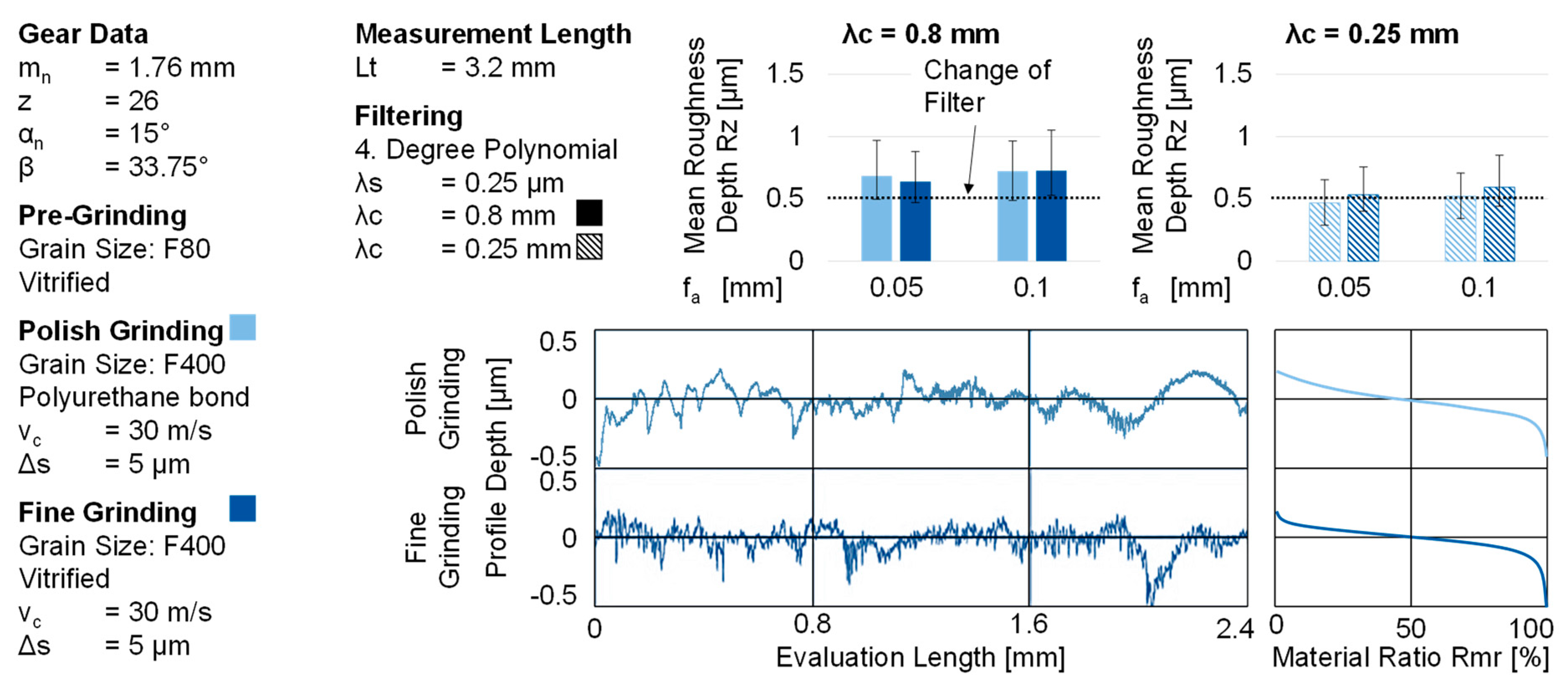
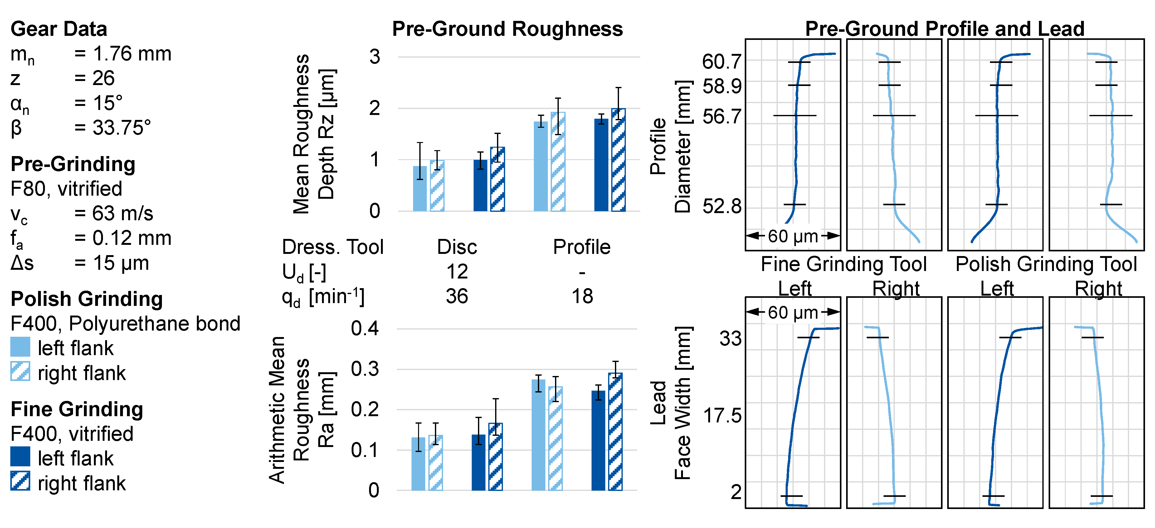
Figure 4, on the left-hand side of the diagrams, the results of the roughness measurements determined over the three discrete measuring points and representative profile measurements of the gears after pre-grinding with the corresponding pre-grinding area of each tool used are shown.
The roughness of the pre-ground tooth flanks for the two grinding tools is comparable with values of the mean roughness depth of Rz ≈ 1 μm. For both of the grinding tools, it is also noted that the right flank has a higher roughness than the left flank. The material ratio Rmr(−0.15 µm) is in the range of Rmr(−0.15 µm) = 28% for both of the pre-grinding tools. The profiles of the pre-ground gears do not deviate between the grinding tools and the quantified average total profile deviation Fα is approximately IT = 3 for both tools. Because the grinding worms were dressed in the same way and profile as well as lead were corrected, these results were expected and they indicate that the initial situations for polish and fine grinding were almost identical.
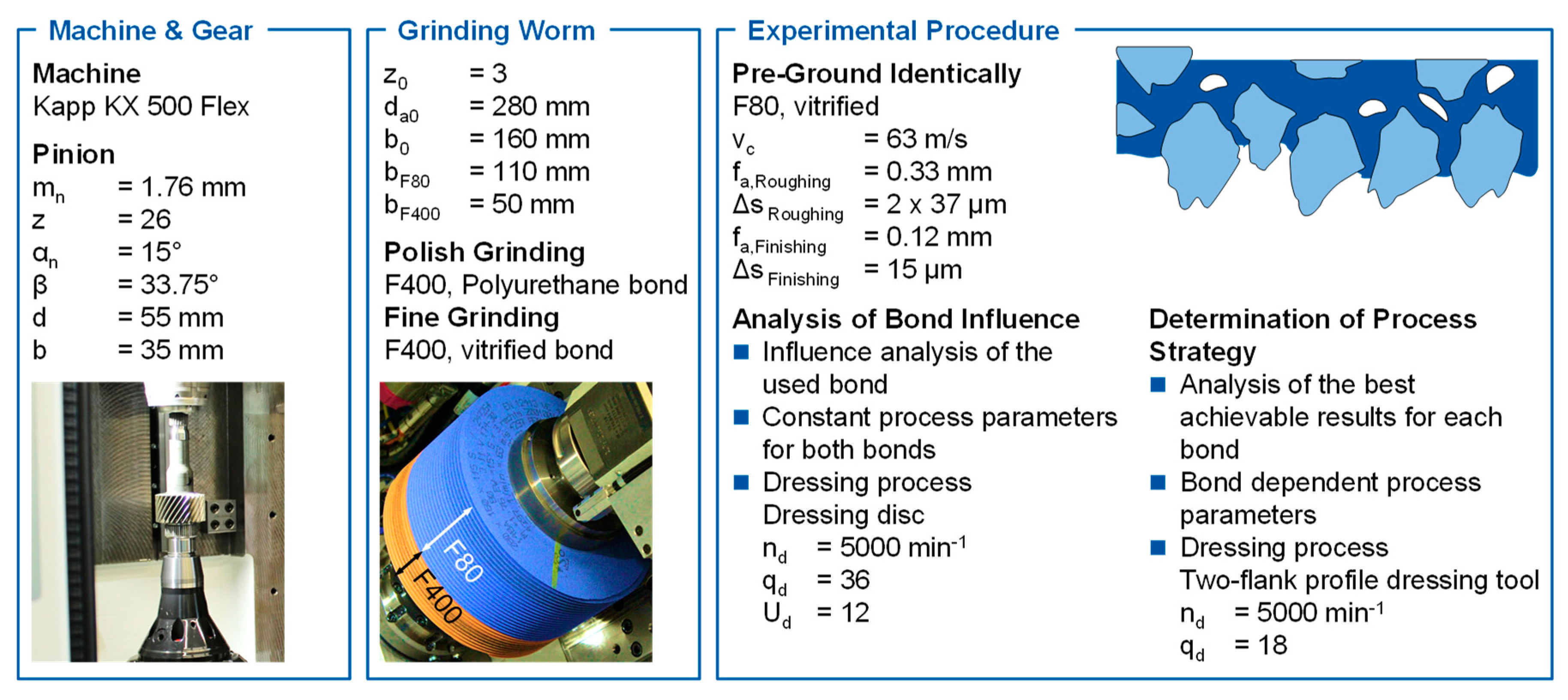
After pre-grinding, fine grinding investigations were carried out with a vitrified grinding worm and polish grinding investigations with a polyurethane bonded grinding worm, each with a grain size of F400. For polish grinding, the grinding worm specifications with a grit size of F800 are already used as a standard [10]. However, the grit sizes of F800 have not yet been tested in vitrified grinding tools. Therefore, a grit with the size of F400 was chosen in order to analyze the influence of the bond system although a grit with the size of F400 is relatively large, when compared to the standard grit size for polish grinding. The cutting speed of vc = 30 m/s was kept constant during the tests. The axial feed fa was equally varied for both grinding worm specifications to fa = 0.05 mm and fa = 0.1 mm. The polish and fine grinding were carried out in two strokes with radial infeed of ae = 19 µm each. The polish and fine grinding process were carried out with the same grinding parameters in order to separate the influence of the bond system from other possible influences.
Because of the fine dressing parameters, the roughness after pre-grinding for both used grinding tools with a grain size of F80 was in the range of a mean roughness depth of Rz = 1–1.2 µm and, thus, in the range of fine ground surfaces. These low surface roughness values were achieved, due to the dressing process using a dressing disc and a high overlap ratio of Ud = 12. However, this dressing process took a long time. In addition, the fine structure of the grinding worm can reduce the cutting performance of the tool. They both negatively affect the productivity.
By comparing the polish and fine ground with the pre-ground gears, it can be seen that the mean roughness depth of Rz = 1–1.2 µm after pre-grinding was reduced to a mean roughness depth of Rz = 0.6–0.8 µm. An influence of the feed rate used fa = 0.05 mm and fa = 0.1 mm is not recognizable. Furthermore, the results of the mean roughness depth do not directly indicate the bond system used. By analyzing the material ratio Rmr(−0.15 µm), no increase in the material ratio Rmr(−0.15 µm) can be determined for the polish ground gears as compared to the pre-ground gears. In contrast, an increase in the material ratio of the fine ground gears from Rmr(−0.15 µm) = 28% after pre-grinding to Rmr(−0.15 µm) = 40–50% can be detected, whereby the fine grinding process with an axial feed of fa = 0.05 mm led to a higher material ratio. The comparison highlights the advantage of a vitrified worm with a grain size of F400 for increasing the material ratio and, thus, the contact ratio of the tooth flank with the used set of parameters. The difference in roughness between the left and right flank after pre-grinding can result from the kinematics during generating gear grinding, since the contact conditions between the worm thread of the leading and trailing flank are different. The dressing process can be used as a further explanation for the slightly higher roughness of the right flank. During the dressing of the grinding worm, the dressing tool rotates at a constant speed of nd = 5000 min−1 and a constant rotational direction. Consequently, the dressing process alternates between counter-rotating and synchronized dressing. This can lead to different topographies of the left and right flanks. In addition, the left and right grinding worm flanks are dressed with different radii of the dressing tool, which can also lead to this slight difference in roughness. Furthermore, the elasticity of the polish grinding worm can lead to geometric deviations during dressing, which was also shown for elastic diamond grinding tools [21].
Based on the evaluations of the mean roughness depth Rz that are presented in Figure 4, only a slight correlation can be found between the polish respective fine grinding parameters and mean roughness depth. However, the correlation is in the range of the scatter of the roughness values and, therefore, not clearly detectable. In the polish grinding of surfaces, the peaks of the roughness profile are typically removed and, thus, the surface is smoothened. The resulting surfaces are characterized by a high material radio Rmr(c) at small distances c [10]. This tendency cannot be observed for the examined polish ground gears. The reason for this might be the relatively large grain size of F400 for polish grinding. With those grains, some roughness peaks might be removed, but relatively large grains can cause new, deep grinding scratches, which results in new roughness peaks. Because of the elasticity of the bond, the polish grinding worm can cause a wavy roughness, which can result in a low material ratio. In further investigations, therefore, a finer grain size of F800 will be used to test whether the expected effect occurs or the polish grinding parameters have to be changed to machine only the roughness peaks and avoid too much material removal.
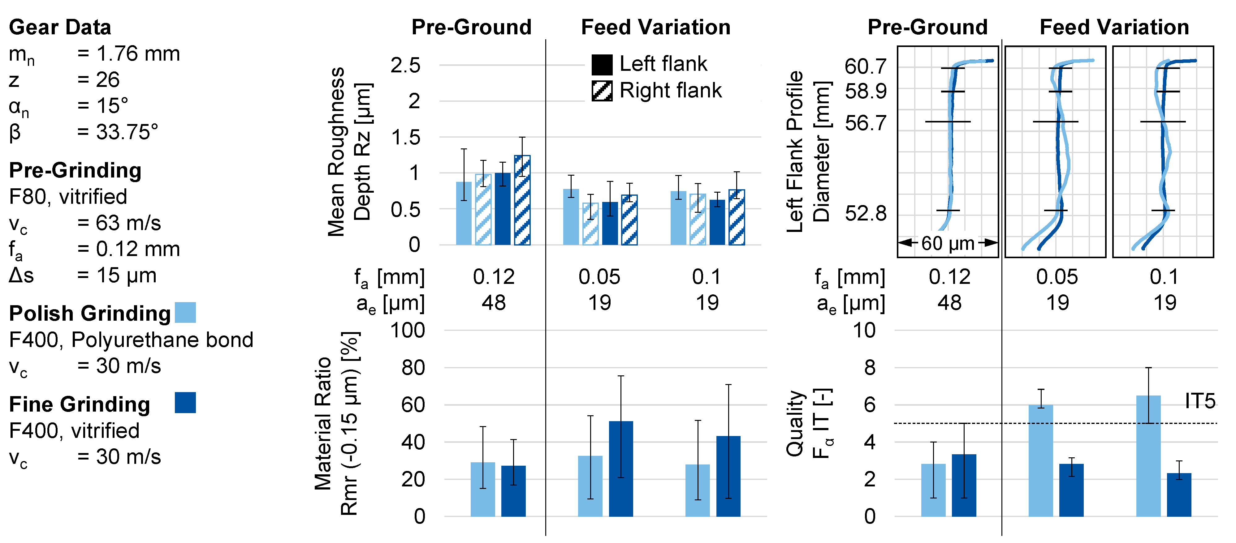
The profiles and the profile qualities Fα are compared on the right side of Figure 4 in order to visualize the gear quality achieved by polish and fine grinding. In case of the fine ground gears, for both axial feeds fa = 0.05 mm and fa = 0.1 mm, no change in the profile can be determined visually, but the measured quality Fα becomes slightly better when compared to the pre-ground gears. The profile of the polish ground gear deviates significantly from the pre-ground and fine ground profile. This can also be seen in the decreasing profile quality Fα up to an IT value of IT = 8. The significant loss of gear quality when compared to pre-grinding can be caused by a different contact pressure between grinding worm and tooth flank over the tooth height. Furthermore, the grinding worm can expand due to the centrifugal force that is caused by the rotational speed of n0 = 2100 min−1 to reach the cutting speed vc = 30 m/s. The grinding worm expands until it is restricted from expanding by the teeth with which the worm is in contact. This effect has already been observed by Wagner for profile gear grinding [10]. According to Wagner, the systematic deviations of the flank profile can be compensated by means of time and material consuming corrections.
The increase in the material ratio after fine grinding can be attributed to the significantly finer grain size when compared to pre-grinding. By using a comparable vitrified bond, after fine grinding a surface that is similar to the pre-ground surface is produced. Because of the finer grain size in a rigid vitrified bond, the resulting surface structure is also finer, which can be measured with the help of the material ratio. The slightly positive influence on the gear quality allows for the conclusion that the grinding worm is not, or is only slightly, elastically deformed in contact with the gear and thus the set nominal geometry of the gear is achieved.
In polish grinding, the significant negative influence on gear quality is caused by the selected disadvantageous parameters for the elastic polyurethane bond. The parameters used were the equal for both polish and fine grinding worm to expose the influence of the bond. However, in the tests to determine a process strategy that is suitable for each of the grinding worm specifications, process parameters were chosen to avoid a negative influence on the profile. Furthermore, the used dressing tool led to very high and unacceptable dressing times; therefore, the use of an industrial standard dressing tool will be investigated in the following.

3.2. Determination of Process Strategy

Further tests had to be carried out in order to determine a suitable process strategy for both polish and fine grinding process. The process strategy had to be adjusted particularly for the polish grinding process due to the negative influence of the elastic bonded polish grinding worm. In the first tests, a dressing disc was used. This led to high dressing process times. In industrial applications, two-flank profile dressing tools are commonly used in order to minimize the dressing process times. Furthermore, the pre-ground roughness was significantly lower than that commonly achieved in industrial grinding. In order to determine the dressing tool influence, the same gear geometry was ground with the same grinding worms and with the same grinding parameters as in the first tests.

3.2.1. Dressing Tool Technology Influence on the Pre-Ground Roughness

In the following, the influence of different dressing tool technologies is analyzed by means of the achieved roughness after pre-grinding, as well as the pre-ground profile and lead. The roughness after pre-grinding with a grain size of F80 is evaluated by means of the mean roughness depth Rz and the arithmetic mean roughness Ra, left side of Figure 5. After pre-grinding with the conventional grinding worm with a grain size of F80 dressed with a dressing disc, the roughness is approximately Rz = 1 µm, respectively, Ra = 0.13 µm. By using an industry standard two-flank profile dressing tool with industry standard dressing parameters, the roughness is approximately Rz = 1.9 µm, respectively, Ra = 0.29 µm. On the right side of Figure 5, the profile and lead of the left and right flanks of two pre-ground gears are shown. The profile and lead correspond to the specifications of the technical drawing. The visible lead angle deviation is part of a modification of the gear used and, therefore, is not an error.
To conclude, the results of pre-grinding can be summarized, where the selected dressing tools had neither a positive nor a negative influence on the workpiece geometry. However, the used dressing parameters and use of a two-flank profile dressing tool led to a roughness that was approximately twice as high as when using a dressing disc with an overlap ratio of Ud = 12. Nevertheless, the time that is required for a single dressing process with the dressing disc was approximately td,disc = 120 min, whereas the dressing process with the two-flank profile dressing tool took only approximately td,profile = 5 min. The use of a dressing disc is preferred, but not recommended from an economic point of view, in order to achieve a very low roughness. However, the full potential of the two-flank profile dressing tool to achieve a low roughness might not yet be fully exploited with the industrial standard dressing parameters.

3.2.2. Influence of the Used Dressing Tool Technology for Polish and Fine Grinding

After determining the influence of the dressing tool on the pre-grinding roughness, the two-flank dressing tool is subsequently used. The further investigations will follow a more industrial process strategy. In the previous investigations, the gear profile was negative influenced. In an industrial application, this negative influence is not acceptable. Therefore, it will be ensured that the profile of the gear is not negatively influenced during polish or fine grinding. In addition, in industrial grinding processes, higher cutting speeds are used in order increase the productivity. Therefore, the influence of cutting speed has to be vc = 63 m/s in order to correspond more to an industrial process strategy.
In the previous tests, the profile was negatively affected. This could be explained by the elasticity and the resulting expansion of the grinding worm. For this reason, the first step of the polish grinding tests is to verify the initial machine infeed position ae,Initial-Contact, where the grinding worm and gear have the first contact. In order to find the initial contact, first, all of the gear was pre-ground. The second step was to paint the gear in order to make the contact between the grinding worm and the gear visible. Afterwards, the first set infeed of the grinding worm was e.g., ae = −80 µm. At this distance, no material was removed. Further, the infeed was set to a lower infeed. When the grinding worm removed some of the paint, the infeed of the initial contact was found, e.g., ae,Initial-Contact = −60 µm. Starting from this initial contact, the machine infeed is successively increased. The gear quality is systematically checked. Thus, in polish grinding, the infeed Δae is relative to the initial contact, as in Equation (1).
Δae = ae,Polish − ae,Initial-Contact
Because the vitrified fine grinding worm is assumed to be stiff, the initial contact of the fine grinding worm and gear is at ae,Initial-Contact = 0 µm. Therefore, in fine grinding, the infeed ae is equal to the relative infeed Δae.
After the gears were pre-ground, the initial contact was determined. From this initial contact, the infeed was successively increased. 
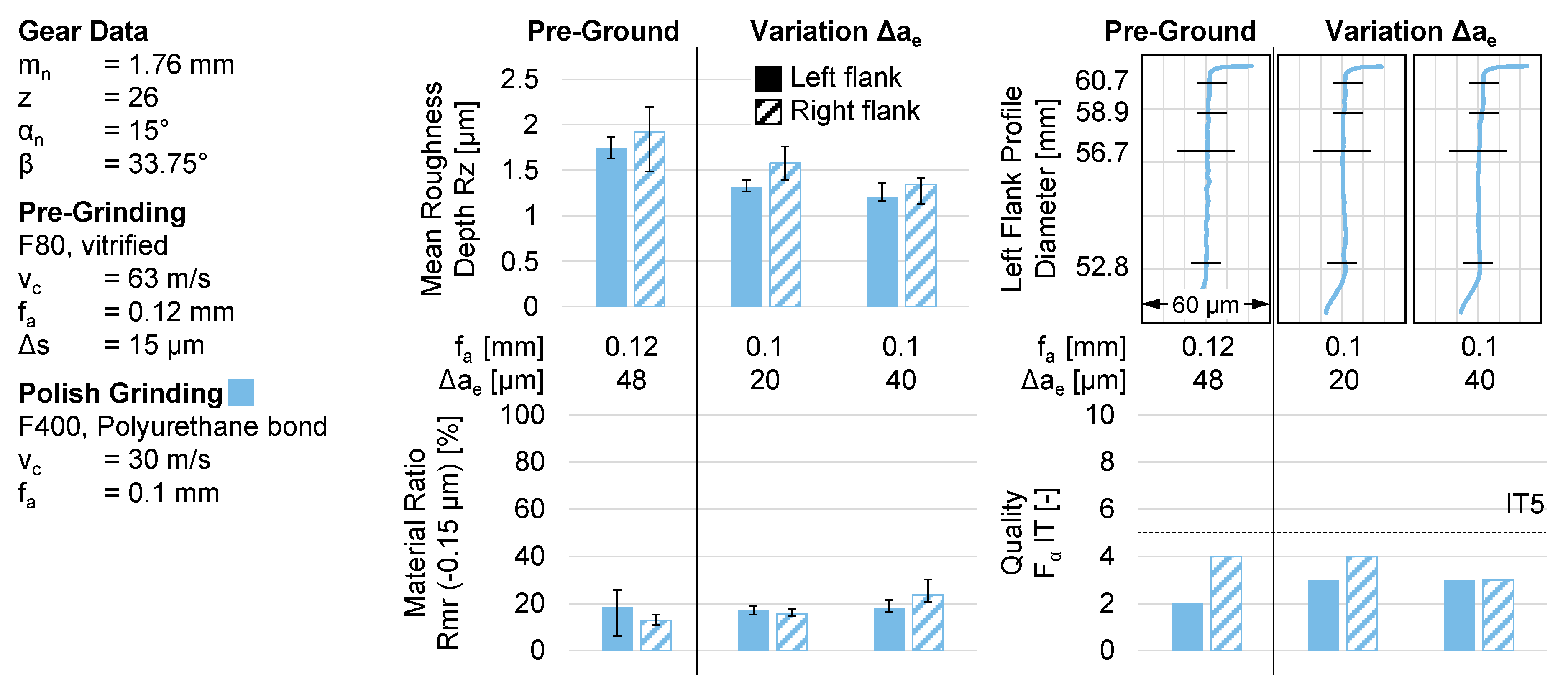
Figure 6 shows the measurement results of polish ground gears with a relative infeed of Δae = 20 µm and Δae = 40 µm. A relative infeed of Δae = 20 µm led to a slight decrease of the roughness, but the material ratio is not affected. With an increasing relative infeed to of Δae = 40 µm, the roughness decreases more, and the material ratio increases slightly. Because of the limitation of the test that the profile should not be influenced negatively, the profile, as well as the profile quality, are not affected by a relative infeed of Δae = 20 µm or by a relative infeed of Δae = 40 µm. In conclusion, a higher relative infeed Δae can lead to a lower surface roughness and an increasing material ratio. However, the high requirements on the gear geometry set a limit to the increase of the relative infeed Δae.
Besides the constant pre-grinding process parameters, the process parameters, respectively, the process strategy, was only adjusted for the polish grinding process. Therefore, the relative infeed was set to Δae = 40 µm for polish grinding. The fine grinding process was kept constant compared to the first test with the dressing disc with an infeed of Δae = 19 µm. The axial feed and the cutting speed for both polish and fine grinding was set to fa = 0.1 mm, respectively, vc = 30 m/s. In Figure 7, the results of pre-ground, polish, and fine ground gears are shown. The grinding worms were dressed with a two-flank dressing tool with standard industrial dressing parameters. After pre-grinding with a grain size of F80, the mean roughness depth is approximately Rz = 1.9 µm and the material ratio is approximately Rmr(−0.15 µm) = 20%. The profile is within the tolerance and the worst measured profile qualities are Fα,left IT = 2 and Fα,right IT = 4. The achieved mean roughness depth with the polish grinding process is approximately Rz = 1.3 µm. While using fine grinding, a mean roughness depth of Rz = 1.1 µm can be achieved. The material ratio Rmr(−0.15 µm) is only slightly increased by the use of polish or fine grinding process as compared to the pre-ground gears. The profile and profile quality are not affected negatively by fine or by polishing grinding. Therefore, the profiles are almost identical to the pre-ground variant and quality Fα changes to IT = 3 for both the polish and fine ground gears.
Because of the two-flank profile dressing tool, the roughness of the pre-ground gears is quite high when compared to the tests with a dressing disc. With the subsequent fine grinding process, the roughness in terms of the mean roughness depth and the material ratio is only slightly reduced. Because the same dressing parameters are used for the vitrified pre-grinding and the vitrified fine grinding section, not only is the pre-grinding area dressed rougher, but also the fine grinding area. This leads to a higher roughness after pre-grinding and after fine grinding. For the grinding worm with the elastic bonded polish grinding section, the same dressing parameters were used and, thus, the roughness was reduced to approximately the same mean roughness depth with the polish grinding process as with the fine grinding process. Because the profile has not been affected negatively, the selected procedure for polish grinding can be considered to be suitable.
The cutting should be increased to an industrial standard cutting speed of vc = 63 m/s, because, in the first tests, and in the tests with the changed dressing tool, a cutting speed of vc = 30 m/s was used. Following, the influence of the cutting speed for fine and polish grinding has to be analyzed with respect to the gained knowledge. Therefore, gears fine and polish ground with these two cutting speeds are investigated by means of the roughness and achieved profile quality.

3.2.3. Cutting Speed Influence

In the first test series with the dressing disc, the cutting speed for polish and fine grinding was set to vc = 30 m/s. In the tests with the industrial standard dressing tool, this cutting speed was kept constant. In industrial grinding processes, higher cutting speeds are necessary in order to increase the productivity. Therefore, the cutting speed has to be increased to an industrial standard of vc = 63 m/s, and the dressing tool was changed to an industrial standard two-flank profile dressing tool. For this reason, the influence of the different cutting speeds used for polish and fine grinding on the roughness, and the profile quality has to be investigated. Therefore, gears are polished and fine ground with grinding worms dressed with the used industrial standard dressing process. Because of the different used cutting speeds and, therefore, the different rotational speeds, the deformation of the elastic polyurethane bonded grinding worm is also expected to be different. For this reason, the first step for the polish grinding process is to determine the infeed of initial contact between grinding worm and gear, according to Equation (1). Subsequently, the relative infeed is set to Δae = 40 µm while using the polish grinding worm for both cutting speeds. The relative infeed of the vitrified fine grinding worm equals the infeed, and it is set to Δae = 19 µm for both cutting speeds. The results of the cutting speed variation are compared in 
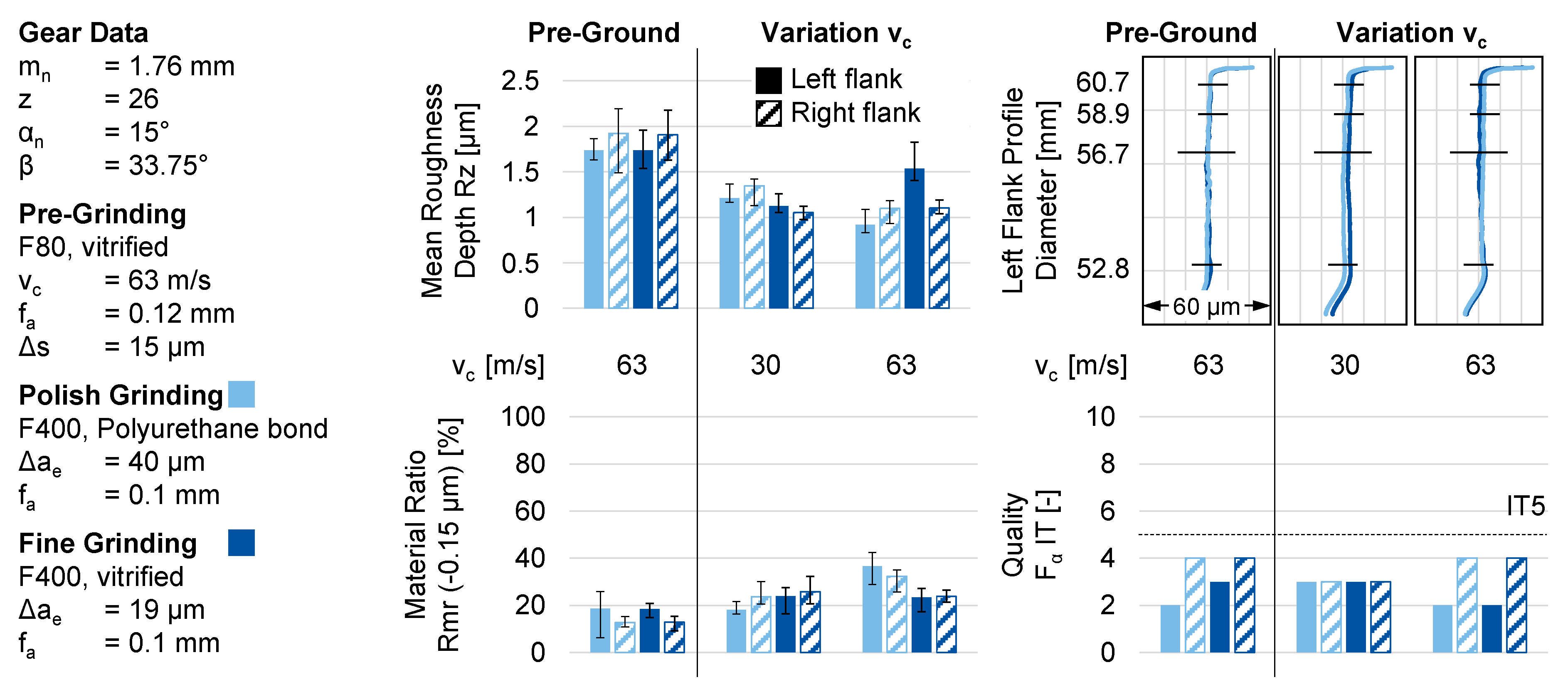
Figure 8 for both polish and fine grinding.
With a cutting speed of vc = 30 m/s, the mean roughness depth is reduced to Rz = 1.4 µm by polish grinding and to Rz = 1.1 µm by fine grinding. While using a cutting speed of vc = 63 m/s for the polish and fine grinding, a mean roughness depth of Rz = 1.1 µm can be achieved, but the roughness of left fine ground flank is Rz = 1.5 µm. By analyzing the material ratio Rmr(−0.15 µm), with a cutting speed of vc = 30 m/s, only a very slight increase in the material ratio can be detected when compared to the pre-ground gear for both the polish and fine ground gears. The use of a cutting speed of vc = 63 m/s only results in a slight increase of the material ratio of the fine ground gear. In contrast, after polish grinding, the material ratio of Rmr(-0.15 µm) = 40% is nearly twice as high as the material ratio of the pre-ground gear. This can be explained due to the use of an elastic bond for polish grinding. Every single grain is elastic bonded. Therefore, the grains can be forced into the bond during the engagement and, thus, the active grain protrusion can be different from the vitrified fine grinding worm. Another explanation can be that the grain engagement path with the elastic bond can be different from the vitrified grinding worm due to the elasticity. These two effects can also occur during the dressing process, which can have an effect on the topography of the polish grinding worm and, consequently, an effect on the roughness of the polish ground gear. The profile is neither negatively influenced by any of the used set of parameters nor by the grinding worms used. The quantified profile quality becomes a little better by using a cutting speed of vc = 30 m/s with both the polish and fine grinding. For both processes, polish and fine grinding, the profile quality is not positively or negatively affected by using a cutting speed of vc = 63 m/s.
Because the aim for the test with the two-flank profile dressing tool was to not negatively influence the gear quality, the results of the course of the profile and profile quality were to be expected. The influence of the polish and fine grinding on the roughness is comparable to the first tests with the dressing disc. In both of the test series, the roughness could be reduced to nearly half of the roughness of the corresponding pre-ground gears. The only remarkable result is that the material ratio Rmr(−0.15 µm) was significantly increased by polish grinding with a cutting speed of vc = 63 m/s. This can be explained with the use of an elastic bonded polish grinding tool. It was already shown that, with elastic bonded polish grinding tools, only roughness peaks are machined [10]. Because of this, the peaks of the ground surface are flattened and, therefore, the material ratio in a peak distance of c = 0.15 µm increases.
The results of the second test series to determine the process strategy are comparable to previous investigations. In a previous investigation, a mean roughness depth of Rz ≤ 1.2 µm was achieved. The running tests of these gears have shown a higher wear resistance and, therefore, a higher number of load cycles that can be sustained [17].

4. Discussion and Conclusions

The first test series was carried out in order to analyze the bond influence. The process parameters were kept constant to determine the influence of the used bond system independent from the process parameters or the grain size. As a result of this test series, the roughness could be reduced with both the polish and the fine grinding process. However, the use of the elastic bonded grinding worm for polish grinding led to a significant negative influence of the profile. During the second test series, it was mandatory that the gear profile should not be negatively influenced. Therefore, the procedure was changed. Because of the elasticity of the polish grinding worm, the worm can expand and, thus, can lead to too high material removal during polish grinding. Therefore, as a first step, the initial contact between the polish grinding worm and gear was determined. Subsequently, a relative infeed of Δae = 40 µm was used for polish grinding. With this procedure, the profile was not negatively influenced.
In addition to the results shown, the roughness profiles of the polish and the fine ground surfaces shall be visually examined. Figure 9 shows the visual comparison of the roughness profiles after pre-, polish, and fine grinding. The difference between the roughness profiles is shown by the profile heights along the evaluation length, which nearly matches the whole gear profile length. Furthermore, the Abbott curve is shown, corresponding to each roughness profile.
The roughness profile of the pre-ground surface has clearly visible roughness peaks and valleys. On the contrary, the profile height of the polish ground variant only shows barely visible valleys and almost no clear roughness peaks. The roughness profile of the fine ground variant is similar in height to the height of the polish ground variant. However, the roughness profile of the fine ground variant shows many small roughness peaks and valleys. The Abbott curve sums up the percentage of material in a certain height of the profile. Because of this, the Abbott curves of the roughness profiles have a high gradient at the beginning and end. In the middle section of the curve, the gradient is lower. The lowest gradient is detectable for the polish ground surface.
By comparing the roughness profiles and the Abbott curves of the different ground surfaces, it becomes clear that the polish ground surface is the smoothest achieved surface. However, the structure after polish grinding does not yet fully have the expected plateau-like shape. Therefore, further investigations will be made in order to determine whether this can be achieved with a grinding tool with a grain size of F800.
The presented results give a further understanding of the processes of fine and polish grinding of gears. Both of the processes are designed to reduce the roughness of gear flanks in order to improve the load-carrying capacity. From the knowledge gained by using an automotive pinion shaft and a process commonly used in the automotive production for the investigations, the automotive branch can especially benefit from the investigation presented. However, other branches where fine or polish ground gears are needed can benefit from these investigations. Furthermore, the results can be transferred to other grinding processes as surface of cutting tool grinding processes.

5. Summary and Outlook

Because of the constantly increasing performance requirements of gears, hard fine machining of gears is necessary in many cases to correct the deviations from the gear hobbing process and heat treatment. One of the established processes for hard fine machining is continuous generating gear grinding. The reduction of the tooth flank roughness by means of grinding increases the load-carrying capacity of the tooth flank. The often required roughness of Rz < 1 μm can, in many cases, not be achieved with conventional vitrified corundum grinding tools. Therefore, gears are increasingly super finished after hard finishing. Chemically supported vibratory grinding and polish grinding with elastic bonded tools are used for super finishing. However, in order to avoid the use of a further process, such as vibratory grinding or polishing with elastic bonded tools, the objective of this report was to analyze the potential of fine grinding with vitrified grinding tools as compared to polish grinding with elastic bonds.
Grinding tests were carried out on identically pre-ground gears in order to determine the potential of fine grinding compared to polish grinding. The same grain size of F400 was used for both polish and fine grinding to minimize the influence of the grain size used. Furthermore, two test series were carried out. One test series with the same grinding parameters for both grinding tools and a dressing disc for a fine dressing process. With the polish and fine grinding process, the tooth flank roughness could be reduced to nearly the same values. A dependence of the tooth flank condition on the selected grinding parameters could not be determined. The material ratio could be increased in all of the test points during fine grinding at the examined distances when compared to pre-grinding. An increase of the material ratio could not be achieved with polish grinding. However, it could be determined that the profile geometry after polish grinding significantly deviates from the preset values if no significant corrections are applied. In contrast, a slight improvement in the achieved gear quality could be determined for fine ground gears.
The second test series was carried out with an industrial standard dressing tool and the restriction that the gear profile should not be negatively influenced. Because of the restrictions, one result of this test series was that the gear geometry was not negatively influenced. In contrast, the roughness after pre-grinding was significantly higher when compared to the first test series, due to the used two-flank profile dressing tool and industrial standard dressing parameters. An increase of the cutting speed to an industrial standard cutting speed led to a significant increase of the material ratio of the polish ground gear.
In future, the investigations should be continued in order to determine the influence of the grain size in both fine and polish grinding. Grit sizes of F800 have already been used in earlier investigations on polish grinding. Therefore, the presented investigations should also be carried out with a finer grain size in order to achieve a further increase in the surface quality. In addition, the potential of the dressing process with a two-flank profile dressing tool to achieve a lower roughness by means of the dressing parameters should be investigated.

Author Contributions

Funding acquisition, T.B., J.B., M.S.; Investigation, M.S.; Project administration, J.B.; Writing—original draft, M.S.; Writing—review & editing, J.B., M.S. All authors have read and agreed to the published version of the manuscript.

Funding

This research was financially supported by the WZL Gear Research Circle.

Data Availability Statement

The data presented in this study are available on request from the corresponding author. The data are not publicly available due to confidential information of an industry collaborator.

Conflicts of Interest

The authors declare no conflict of interest.

References

  1. Karpuschewski, B.; Knoche, H.-J.; Hipke, M. Gear Finishing by Abrasive Processes. CIRP Ann. Manuf. Technol. 2008, 57, 621–640. [Google Scholar] [CrossRef]
  2. Klocke, F.; Brecher, C. Zahnrad- und Getriebetechnik. Auslegung—Herstellung—Untersuchung—Simulation, 1st ed; Hanser: Munich, Germany, 2017. [Google Scholar]
  3. Weck, M. Moderne Leistungsgetriebe: Verzahnungsauslegung und Betriebsverhalten, 1st ed.; Springer: Berlin/Heidelberg, Germany, 1992; ISBN 3-540-53748-1. [Google Scholar]
  4. Hohle, A.C. Auswirkungen von Rauheit, Oberflächenstruktur und Fertigungsabweichung auf das Lauf- und Geräuschverhalten. Ph.D. Thesis, RWTH Aachen University, Aachen, Germany, 2003. [Google Scholar]
  5. Bausch, T. Innovative Zahnradfertigung. Verfahren, Maschinen und Werkzeuge zur kostengünstigen Herstellung von Stirnrädern mit hoher Qualität, 3rd ed.; Expert: Renningen, Germany, 2006; Volume 175. [Google Scholar]
  6. Klocke, F. Manufacturing Processes 2: Grinding, Honing, Lapping; Springer: Berlin/Heidelberg, Germany, 2009. [Google Scholar]
  7. Hoffmeister, H.-W.; Denkena, B. Jahrbuch Schleifen, Honen, Läppen, Polieren: Verfahren und Maschinen, 63th ed.; Vulkan: Essen, Germany, 2007; ISBN 3-802-72941-2. [Google Scholar]
  8. Türich, A. Werkzeugprofilgenerierung beim Wälzschleifen. Ph.D. Thesis, Hannover University, Hannover, Germany, 2002. [Google Scholar]
  9. Köhler, T. Innovative Honwerkzeuge und Abrichträder. In Proceedings of the Feinbearbeitung von Zahnrädern, Aachen, Germany, 11–12 October 2005. [Google Scholar]
  10. Wagner, A. Feinschleifen von Verzahnungen mit elastischen Schleifscheiben. Ph.D. Thesis, Bremen University, Bremen, Germany, 2017. [Google Scholar]
  11. DIN 3990 Part 1, Tragfähigkeitsberechnung von Stirnrädern. Einführung und allgemeine Einflußfaktoren; Beuth Verlag GmbH: Berlin, Germany, 1987.
  12. Winkelmann, L.; El Saeed, O.; Bell, M. The Capacity of Superfinished Vehicle Components to Increase Fuel Economy. Gear Technol. 2009, 1, 50–60. [Google Scholar]
  13. Koller, P. Steigerung der Zahnflankentragfähigkeit durch Optimierung von Eigenspannungs- und Oberflächenzustand. Ph.D. Thesis, Munich Technical University, Munich, Germany, 2013. [Google Scholar]
  14. Stahl, K.; Tobie, T.; König, J. Tragfähigkeit Gestrahlter und Gleitgeschliffener Zahnflanken unter Besonderer Berücksichtigung des Randzonen- und des Schmierfilmzustands; Abschlussbericht zum FVA Forschungsvor-haben Nr. 521 II, Heft 1245; Forschungsvereinigung Antriebstechnik e.V.: Frankfurt, Germany, 2017. [Google Scholar]
  15. Heinzel, C.; Wagner, A. Fine finishing of gears with high shape accuracy. CIRP Ann. 2013, 62, 359–362. [Google Scholar] [CrossRef]
  16. Kampka, M.; Klocke, F.; Löpenhaus, C. Feinstprofilschleifen von Verzahnungen mit unterschiedlichen Werkzeugkonzepten. In Proceedings of the Schweizer Schleif-Symposium, Zurich, Switzerland, 19–20 January 2016. [Google Scholar]
  17. Graf, W. Optionen des Verzahnungswälzschleifens zur gezielten Beeinflussung von Werkstückoberflächen. In Schleifen, Honen, Läppen und Polieren: Verfahren und Maschinen, 68th ed.; Hoffmeister, H.-W., Denkena, B., Eds.; Vulkan: Essen, Germany, 2018; ISBN 978-3-8027-3091-7. [Google Scholar]
  18. DIN EN ISO 4288. Regeln und Verfahren für die Beurteilung der Oberflächenbeschaffenheit; Beuth Verlag GmbH: Berlin, Germany, 1998. [Google Scholar]
  19. DIN EN ISO 4287. Geometrische Produktspezifikation (GPS) Oberflächenbeschaffenheit: Tastschnittverfahren. Benennungen, Definitionen und Kenngrößen der Oberflächenbeschaffenheit; Beuth Verlag GmbH: Berlin, Germany, 2010. [Google Scholar]
  20. Schriefer, H. Kontinuierliches Wälzschleifen von Verzahnungen, 1st ed.; Reishauer: Wallisellen, Switzerland, 2008. [Google Scholar]
  21. Kipp, M.; Biermann, D. Polierschleifen—Herausforderungen beim Abrichten elastisch gebundener Diamantschleifwerkzeuge für die Hartfeinbearbeitung von Hartmetall. In Forum Sonderausgabe; ISF Technical University Dortmund: Dortmund, Germany, 2018; pp. 136–140. [Google Scholar]
Figure 1. Increase of the load-carrying capacity by reducing the roughness according to [13].
Jmmp 05 00004 g001
Figure 2. Experimental setup and procedure.
Jmmp 05 00004 g002
Figure 3. Influence of the waviness filter and roughness profile of polish and fine ground flanks.
Jmmp 05 00004 g003
Figure 4. Results of pre-grinding as well as polish and fine grinding with a feed variation.
Jmmp 05 00004 g004
Figure 5. Results of pre-grinding with different dressing tool technologies.
Jmmp 05 00004 g005
Figure 6. The results of polish ground gears with different relative infeed.
Jmmp 05 00004 g006
Figure 7. Results of polish and fine grinding with a two-flank profile dressing tool.
Jmmp 05 00004 g007
Figure 8. Results of polish and fine grinding with varied cutting speeds.
Jmmp 05 00004 g008
Figure 9. Roughness profiles of pre-, polish, and fine ground gears.
Jmmp 05 00004 g009
Publisher’s Note: MDPI stays neutral with regard to jurisdictional claims in published maps and institutional affiliations.

