Article

The Influence of CaCl2-Blended Acrylic Polymer on Steel Rebar Corrosion and Acid Attack Resistance of Mortar

by
Obinna Onuaguluchi
* and
Nemkumar Banthia
Department of Civil Engineering, University of British Columbia, 6250 Applied Science Lane, Vancouver, BC V6T 1Z4, Canada
*
Author to whom correspondence should be addressed.
Corros. Mater. Degrad. 2022, 3(1), 160-177; https://0-doi-org.brum.beds.ac.uk/10.3390/cmd3010009
Submission received: 1 February 2022 / Revised: 3 March 2022 / Accepted: 7 March 2022 / Published: 10 March 2022

Abstract

:
A realistic forecast of the impact of CaCl2-blended acrylic polymer (CP) emulsions on steel reinforcement corrosion is difficult without a detailed study. This is traceable to the conflicting effects of cement additives on the chloride threshold value, pore solution chemistry, and matrix resistivity. Hence, in the study reported herein, the actual influence of 0.5–1.5 wt% CP on rebar corrosion was assessed via an accelerated corrosion test. The macrocell current, half-cell potential measurements (HCP), reinforcement cover crack propagation, and rebar deterioration were monitored. The resistance of mortar specimens to acid-induced degradation was also evaluated over time. The corrosion test results indicate that steel rebar corrosion initiation in the mortar expedited as the CP dosage in mixtures increased. Consequently, the time required for the CP-modified specimens to crack shortened. Moreover, non-uniform rebar section loss and surface crack width widening were also observed in CP-modified mortar specimens. However, X-ray diffraction (XRD) analyses of the plain Ref and 1.5% CP corrosion byproduct residues indicated that key phases such as akaganeite, goethite, lepidocrocite, hematite, and magnetite were quantitatively similar. Interestingly, the addition of 1.0–1.5% CP to mixtures enhanced the acid attack resistance of mortars. For now, these results indicate that CP should only be used as a chemical admixture in unreinforced cement composites.

1. Introduction

The capacity of calcium chloride (CaCl2) to accelerate early-age strength gain in cement composites is well known. However, given that chloride-induced steel reinforcement corrosion is a major cause of reinforced concrete (RC) durability problems worldwide, the use of chlorides and chloride-based admixtures in cement composites is prohibited by building standards such as British Standard European Norm BS EN 206-1 [1]. Permissible dosages of water-soluble chloride ions for RC subjected to different exposure conditions are also stringently regulated by building codes such as the American Concrete Institute (ACI) 318 [2]. Moreover, many studies [3,4,5] have also been dedicated to evaluating chloride–cement matrix interactions and establishing the critical chloride threshold for the initiation of steel reinforcement corrosion. This critical chloride content is mostly expressed as free/total chloride and the chloride-to-hydroxyl ion ratio [Cl]/[OH]. However, a wide scatter in chloride threshold values and conflicting effects on reinforcement corrosion exist in the literature. Andrade and Page [3] investigated the effects of sodium chloride (NaCl) and calcium chloride (CaCl2) on reinforcement corrosion at the same total chloride content of 0.4–1.0%. They observed that despite the lower [Cl]/[OH] ratio and reduced free chloride content of the pore solution, rebar corrosion was more aggressive in CaCl2-blended paste mixtures. Relative to the NaCl-blended mortar, Pruckner and Gjørv [4] observed an increased pore solution [Cl]/[OH] ratio in CaCl2-blended mortar. Consequently, a higher rebar corrosion risk in CaCl2-blended mortar was confirmed in their study. The chloride threshold value has also been shown to be dependent on the chloride source being internal or external. For concrete, externally exposed to either CaCl2 or NaCl, Xu et al. [5] observed that the former had a higher chloride threshold value. Conversely, for concrete internally admixed with either of the two chemical additives, the [Cl]/[OH] ratio and risk of reinforcement corrosion were higher in the CaCl2-admixed concrete.
Further complicating the uncertainty about the chloride threshold required to initiate steel reinforcement corrosion in chloride-blended cement composites is the proclivity of cations such as calcium ions to promote chloride binding in the calcium silicate hydrate (C-S-H). Indeed, several studies [6,7,8,9] have shown that, in the presence of CaCl2, the calcium ion concentration in the pore solution increased and the pH decreased. Consequently, the chloride binding capacity of the C-S-H which invariably helps in decreasing the chloride concentration in the pore solution is enhanced. On the other hand, it has been shown that silica fume (SF) reduces the chloride binding capacity and elevates the pore solution [Cl]/[OH] ratio [10,11,12]. Nonetheless, test results showing improved rebar corrosion resistance in SF-modified cement composites also abound [13,14,15]. Therefore, it does seem that the impact of SF on steel reinforcement corrosion is dependent on whether the reduced moisture transport brought about by its incorporation in a cement composite significantly outweighs its negative influence on the pore solution [Cl]/[OH] ratio. To minimize steel reinforcement corrosion risk in RC, maximum dosages of 0.3% and 1.0% water-soluble chloride ions by weight of cement [2] are recommended for RC subjected to moisture/no external chloride source and dry exposure conditions, respectively. According to the American Society of Concrete Contractors (ASCC) Position Statement 31 [16], 0.98% chloride ions by mass of cement translates to an equivalent of 2.0% flake CaCl2 by mass of cement. This implies that, barring other sources of chloride intrusion, the water-soluble chloride ion content of moisture-protected RC incorporating up to 2.0% flake CaCl2 would be within the chloride limit specified by ACI 318 [2].
Chemical reactions between acids and cement hydrates are quite destructive. They impair the durability of cement composites as a result of matrix leaching, the formation of expansive products, micro-cracking, and loss of strength. However, research findings by Shaker et al. [17] showed that, relative to the plain reference concrete, sulfate attack-induced loss of compressive strength was lower in concrete modified with 15% styrene–butadiene rubber (SBR) polymer latex. Rossignolo and Agnesini [18] investigated the acid attack resistance of plain and 5–10% SBR-modified lightweight concrete specimens exposed to concentrated (sulfuric, acetic, and hydrochloric) acid solutions. For all the exposure conditions, the performance of the SBR-modified mixtures was significantly superior to that of the plain concrete. In a recent study, Sokolova [19] reported enhanced acid attack resistance, and the absence of corrosion in a steel reinforcement bar embedded in a polymer silicate concrete consisting of carbon-rich mineral (schungite and shungizite) components. However, a poor performance of polymer-modified cement composites to acid attack has also been reported. Monteny et al. [20] highlighted the contradictory effects of different types of polymers (7.5 wt%) on the sulfuric acid resistance of concrete. Indeed, the findings by [21] indicated that while acrylic/styrene–butadiene-based polymers reduced the acid attack resistance of concrete, enhanced resistance was observed in concrete modified with styrene/acrylic ester polymer. A related study by Pacheco-Torgal and Jalali [22] showed that the admixing of 0.8–2.0% melamine and 10% SBR to mixtures had a negligible impact on the sulfuric acid resistance of concrete pipes. From the foregoing, it is apparent that the acid resistance of polymer-modified cement composites is dependent on the type of polymer utilized.
Recent studies by [23,24] have shown that small dosages of CaCl2-blended acrylic polymer emulsion (CP) ameliorated drawbacks such as delayed setting and strength loss normally associated with acrylic polymer-modified cement composites subjected to moist curing. The CP also reduced moisture transport and alkali–silica reactivity in cement mortar. However, it is uncertain if the reduced moisture transport engendered by the CP could offset the negative effect of the increased pore solution [Cl]/[OH]. Therefore, the main objective of this study was to evaluate the possibility that CP could enhance or worsen steel rebar corrosion risk in cement mortar mixtures. An additional objective was the verification of whether small dosages of CP could also enhance the acid attack resistance of cement mortar.

2. Experimental Methods

2.1. Materials

General use (GU) Portland cement and a natural fine aggregate with a specific gravity of 2.65 were used. The gradation of the fine aggregate is such that about 98% of the particles are less than 2.36 mm in size. The only chemical admixture used was a milky white-colored CaCl2-blended acrylic polymer emulsion hereby identified as CP (Formula WS of the Polymerpave Global Corporation, Pointe-du-Chene, NB, Canada). The CP has an acrylic/styrene copolymer as its principal polymer composition. The chemical properties of CP are shown in Table 1. A hot-rolled, deformed, carbon steel, Grade 400 W rebar having the chemical composition shown in Table 2 was also used for the accelerated corrosion test.

2.2. Mixture Proportion and Specimen Preparation

Mortar mixtures with a w/c ratio of 0.50, sand/cement (s/c) ratio of 2.0, and CP contents of 0%, 0.5%, 1.0%, and 1.5% by weight of cement were prepared and identified as Ref, 0.5 CP, 1.0 CP, and 1.5 CP, respectively. Specimens were moist cured for 14 days at 23 °C and 98 ± 3% RH in a curing room. A Hobart mixer meeting the ASTM C305 [24] specifications was used in preparing all cement mortar mixtures. Information about the splitting tensile strength and moisture sorption properties of the respective mixtures after the curing period is presented in Table 3.

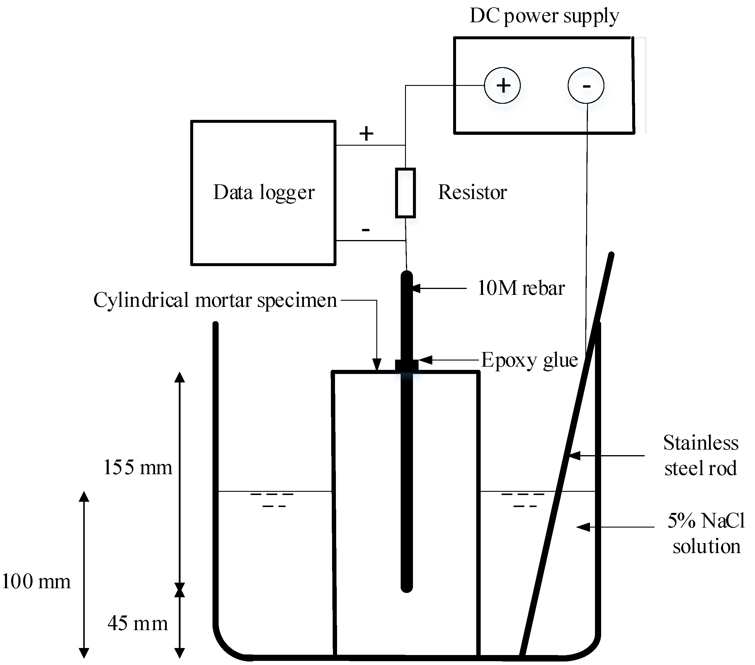
2.3. Accelerated Corrosion Test

For each mortar mixture, three 100.0 mm × 200.0 mm cylindrical specimens with a 10 mm steel reinforcement bar, centrally embedded in each specimen, were prepared. The steel rebar was embedded in such a way that a 45.0 mm all-round cover of the reinforcement bar was achieved. The rebar embedded length and surface area in mortar specimens were 155.0 mm and 5503 mm2, respectively. Before embedding the steel reinforcement bars, reinforcements were cleaned thoroughly using an acetic acid solution, and the initial mass was determined. After 14 days of curing in the moist room, specimens were partially immersed to about half-height in a container of 5% NaCl solution, as shown in Figure 1. The partial immersion of specimens in the 5% NaCl test solution was to ensure oxygen availability in the specimens. To minimize the negative effect of specimen temperature rise on the electrochemical process, a low impressed voltage of 7.5 V was used in accelerating the corrosion test. The power supply instrument used was a READER Regulated (30V 3A) DC Power Supply. The embedded steel rebar, which was the working electrode, was connected to the positive pole of the DC power supply. For the counter electrode, a 2.4 mm-diameter, corrosion-resistant, Type 316 Grade stainless-steel rod which conforms to the ASTM A276 [25] specifications was used. Based on outcomes from trial tests, local corrosion at the location where the steel rebar protruded from the specimen top surface was prevented through the application of an epoxy glue coating around the steel rebar. With a constant applied voltage, the current flowing through the embedded rebar evolved as the resistivity of the overlaying mortar changed with time. All tests were performed at 23 ± 1.0 °C, and the rebar corrosion current data were acquired at one-second intervals using a personal computer as the data logger. The current density was calculated by normalizing the measured current with the surface area of the embedded section of the steel rebar. Faraday’s theoretical corrosion-induced mass loss was calculated using Equation (1):
m = M Q Z F  
where m is the theoretical rebar mass loss, M is the molar mass of Fe (55.847 g/mol), Z is the valency of Fe (2.0), F is Faraday’s constant, 96,485 (C/mol), and Q, which is a product of the corrosion current I (A) and time T (s), is the total electric charge transmitted. For a given elapsed time, Q was calculated using Equation (2):
Q = 0 T I   d t  
where I and T are as previously defined.
For each specimen, monitoring of corrosion-induced crack width propagation commenced once crack initiation was visually observed during the test. Images of longitudinal cracks in specimens were taken daily with a high-resolution digital camera until the end of the test period. Thereafter, these images were processed using ImageJ, an open-source image analysis software [26]. At the end of the accelerated corrosion test, extracted reinforcements were cleaned with a wire brush before being left for 24 h in an acetic acid solution. Thereafter, reinforcements were re-brushed, dried, gently sandblasted using a pressure of 85 psi, and weighed. This type of cleaning procedure is allowed in the ASTM G1-03 [27].

2.4. Half-Cell Potential Test

The ASTM C876 [28] half-cell potential (HCP) test was used in monitoring corrosion risk in the steel reinforcement bar embedded in specimens. HCP measurements were taken at three locations along the height of three specimens from each mixture using a copper–copper (II) sulfate electrode (CSE). Whereas the initial HCP measurement was performed before the commencement of the accelerated corrosion test, the rest of the measurements were subsequently taken at 24 h intervals until the test was terminated. To prevent the impressed voltage from conflating HCP measurements, and also ensure that the moisture content in specimens was relatively similar at every measurement time, HCP readings were taken after the power supply was disconnected and specimens were removed from the test solution and wiped to a saturated surface-dry condition.

2.5. XRD Analysis of Corrosion Byproduct

Given that the [Cl]/[OH] ratio, which is one of the critical factors influencing corrosion byproduct formation [29], could be altered by the CaCl2 contained in the CP, X-ray diffraction analyses (XRD) of powdered corrosion byproduct residues obtained from reinforcements embedded in the Ref and Ref + 1.5 CP mortar mixtures were performed to verify this possibility. Rebar corrosion residues were ground into a fine powder and then smeared onto zero-diffraction quartz plates with ethanol. Step-scan X-ray powder diffraction data were collected over a range of 3–80° 2θ with CoKα radiation on a Bruker D8 Advance Bragg–Brentano diffractometer (Bruker, Milton, ON, Canada) equipped with a Fe monochromator foil, 0.6 mm (0.3°) divergence slit, incident- and diffracted-beam Soller slits, and a LynxEye-XE detector. The long fine-focus Co X-ray tube was operated at 35 kV and 40 mA, using a take-off angle of 6°.

2.6. Acid Attack Resistance

After 14 days of moist curing, three 50 × 50 × 50 mm3 specimens from each mixture were immersed in a 0.5 M hydrochloric acid (HCl) solution for a 28-day duration. The pH of the test solution was measured before specimen immersion and at 3, 7, and 14 days. At the end of the first 14 days of specimen immersion, the test solution was replaced, and a second cycle of measurements was undertaken. Another set of three 50 × 50 × 50 mm3 specimens from each mixture was moist cured for 28 days, and thereafter, changes in the compressive strength of moist-cured and acid-immersed specimens were determined.

3. Results and Discussions

3.1. Accelerated Corrosion Test

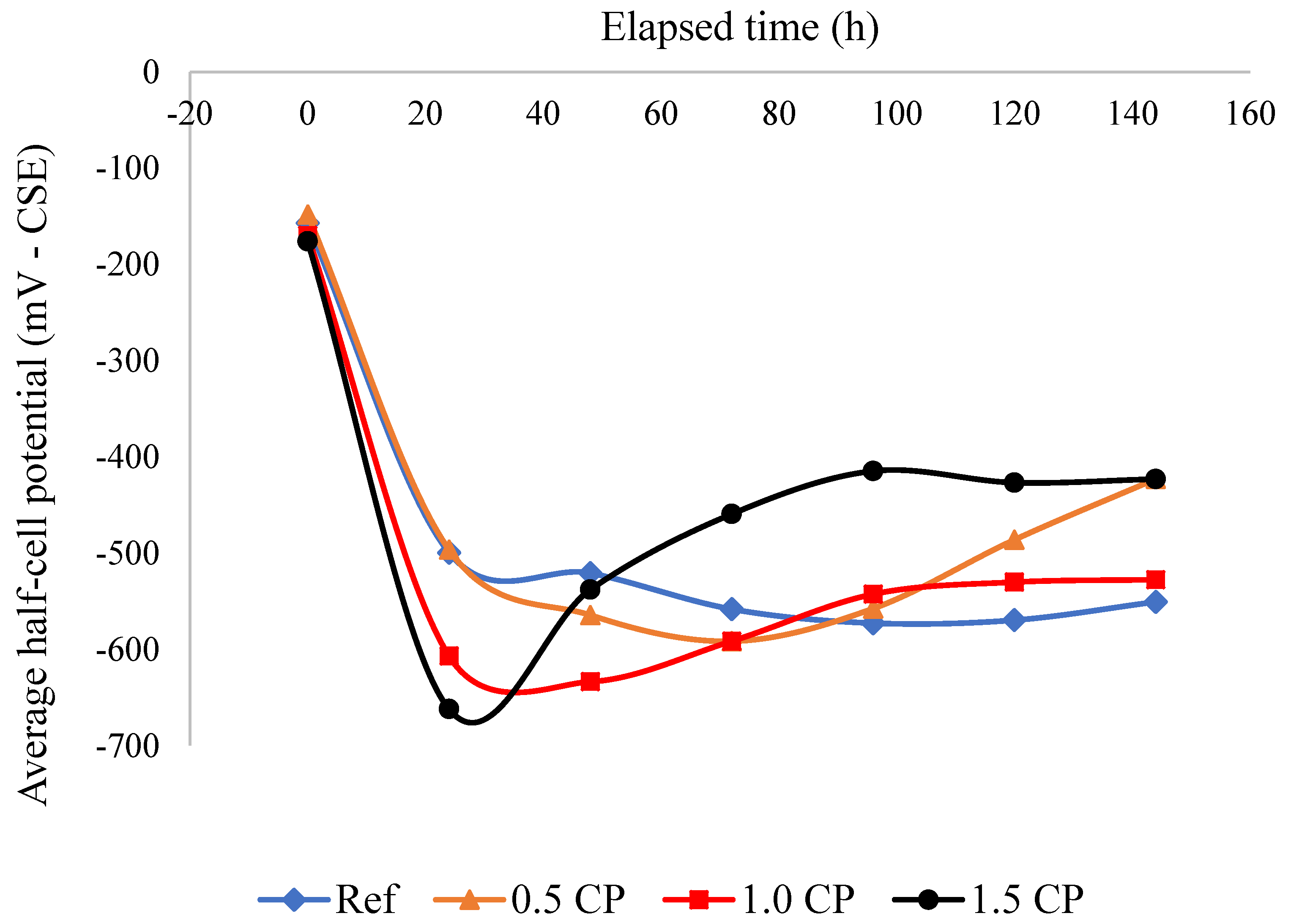
3.1.1. Half-Cell Potential

The initial HCP readings shown in Figure 2 indicate that embedded reinforcement bars were inert and differences in measured values were relatively small. However, after the first day of the test, HCP measurements became more electronegative with increasing CP content in the mortar. HCP values of −499.0 mV for Ref, −497.0 mV for 0.50 CP, −607.0 mV for 1.0 CP, and −662.0 mV for 1.5 CP were measured after 24 h of running the corrosion test. According to the ASTM C876 [28] specifications, there was more than a 90.0% probability that all the specimens were actively corroding. Specifically, these results suggest that relative to the Ref mortar, the risk of rebar corrosion was the highest in CP-blended mortar specimens. The increasing electronegative HCP values recorded for the CP-blended mortar mixtures in the first 24 h are ascribed to the higher degree of rebar oxidation in these mortar specimens.
A reversal of the HCP trend of the rebar embedded in CP-modified mixtures after 24 h is also highlighted in Figure 2. Similar reversals in the HCP of the steel rebar embedded in cement composites have been reported in previous studies [29,30]. According to [31], the increase in potential is due to the build-up of oxide layers on the rebar surface and changes in its chemical composition over time. Indeed, Figure 2 shows that the rapidity of the HCP increase after the first 24 h was the highest in the rebar embedded in the most conductive mortar (1.5 CP), followed by the rebar in the 1.0 CP mortar. This is an indication that the increased dosages of CaCl2 in mortar mixtures increased steel rebar corrosion and byproduct deposition. The data shown in Figure 2 also suggest that the HCP of most of the reinforcement bars attained some measure of stability between 72 h and 140 h. Note also that, fluctuations in the embedded rebar HCP measurements are typical. Variations in HCP readings occur as a result of the interplay of factors such as corrosion byproduct filling/erosion from cracks in specimens [32], and oxygen availability [33].

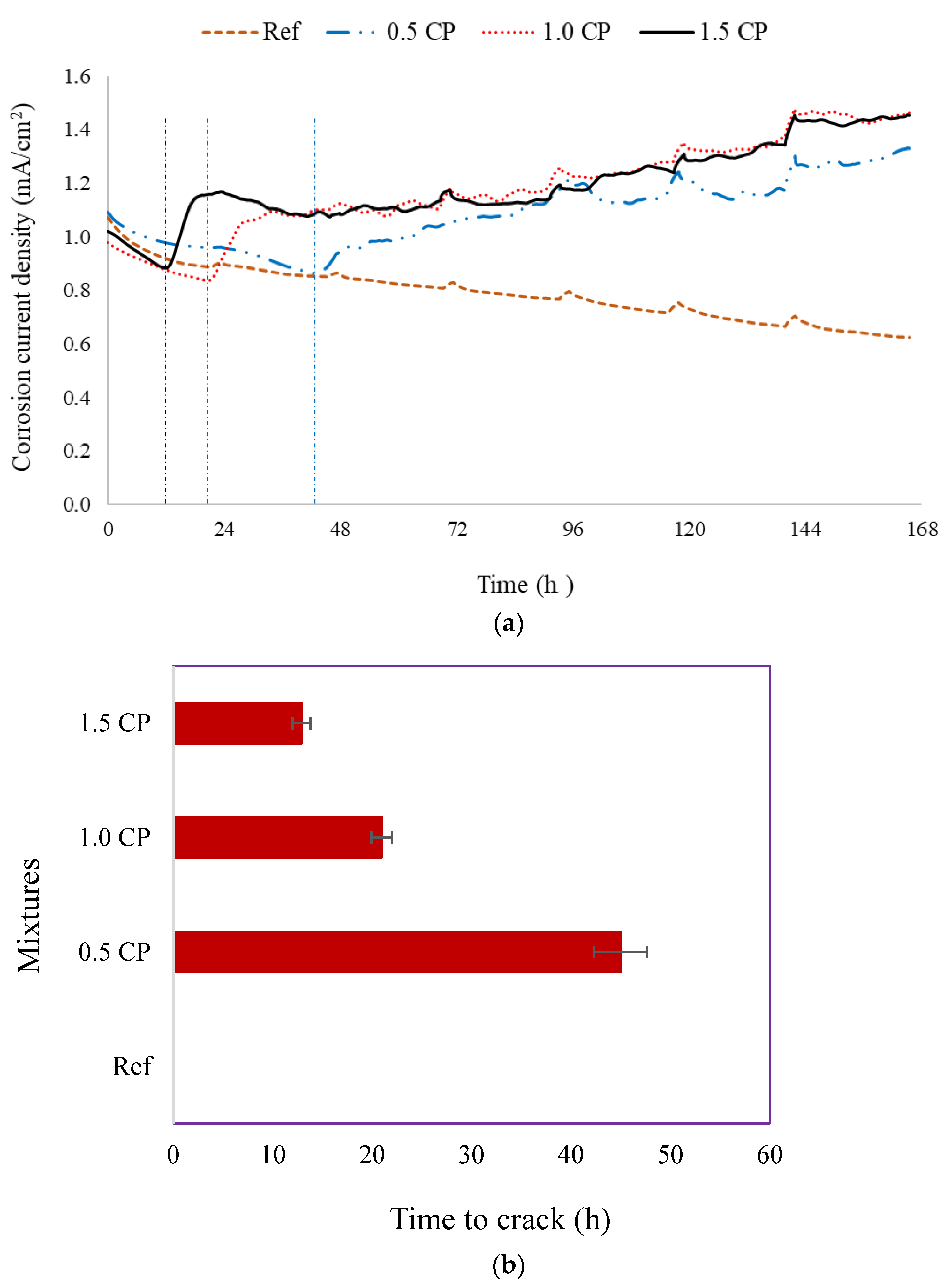
3.1.2. Corrosion Current Density and Crack Time

Average corrosion current densities of the steel rebar embedded in the plain Ref and CP-modified mortar mixtures are shown in Figure 3a. While Figure 3a indicates three corrosion current trends for CP-modified mortar mixtures, a single trend is highlighted for the plain Ref mortar. The gradual decrease in the corrosion current density observed in both Ref and CP-modified mixtures is traced to the electrolysis of water in the pores, and the evolution of the oxygen gas associated with the reaction [34,35]. Consequently, the increased oxygen concentration at the rebar surface led to surface oxidation and the formation of iron oxide layers. According to [34], the resistivity of an iron oxide layer is higher than that of an uncorroded steel rebar [34]. Hence, the sustained deposition of iron oxide on the steel rebar surface caused the corrosion current density to continue decreasing inevitably until the oxide layer was thick enough to induce micro-cracking of the rebar mortar cover.
The presence of chlorides in the pore solution of the CP-modified mortar mixtures was another factor that influenced rebar corrosion activity. The first consequence of internal chloride in CP-modified mixtures is that, relative to the steel rebar embedded in the plain Ref mortar, the presence of these chlorides in CP would have undermined the formation of the passive film layer on the rebar surface after specimen casting. A high pH is an essential requirement for rebar passivation. Therefore, because CaCl2 usually reduces the pore solution pH [4,36], it is expected that the quality of the steel rebar passivation process in CP-modified mixtures would not be at par with that of the rebar embedded in the plain Ref mortar. Secondly, the existence of chloride ions in the pore solution of CP-modified mixtures lowered the resistivity of these mortar specimens relative to that of the plain Ref mortar. Consequently, the steel rebar corrosion became more rapid as the CP dosage in mixtures became higher. Research findings by Enevoldsen et al. [37] confirmed that steel rebar corrosion was higher in low-resistivity cement composites.
Besides the heightened corrosion activity in CP-modified mixtures, the reported reduced porosity of the interfacial transition zone (ITZ) in cement composites modified with polymer admixtures [38] is also a militating factor. This is because, relative to the Ref mortar, the less permeable ITZ of a rebar embedded in CP-modified mixtures may have limited the transportation of byproducts generated by corrosion away from the rebar surface. As a consequence of this, the time frame for the accumulation of oxide layers and the generation of a micro-crack inducing expansive pressure at the rebar-matrix interface became progressively shorter as the CP dosage in mixtures increased. A related phenomenon whereby easier migration of a corrosion byproduct in a more porous, higher w/c ratio mortar led to a reduced oxide layer thickness relative to the denser mortar was reported by Caré and Raharinaivo [39]. Thus, with the rapid accumulation of the oxide layer and the initiation of micro-cracks, the corrosion current in the CP-modified mortar specimens increased abruptly (see vertical dashed lines in Figure 3a). Previous studies [40,41,42,43] indicated that once the tensile stresses produced by an expansive corrosion byproduct layer exceed the tensile strength of the cement matrix contiguous to a corroding rebar, cracking at the rebar–matrix interface is initiated. For the steel rebar embedded in the Ref mortar, it is expected that the rebar corrosion current density would continue decreasing until the more porous rebar ITZ is substantially filled up with iron oxide, and expansive stress and micro-cracks are developed at the rebar interface.
Information about the average elapsed time before micro cracking occurred in specimens is summarized in Figure 3b. The data shown in Figure 3b indicate that while no micro-cracking of the rebar cover was observed in the plain Ref specimens, the average crack time of the CP-modified mortar specimens was 45.0 h for 0.5 CP, 20.9 h for 1.0 CP, and 12.9 h for 1.5 CP. Although these expedited micro-crack occurrence times observed as the CP content of the mortar increased are quite abysmal, they are in perfect agreement with the HCP measurements reported in Section 3.1.1.
Reinforcement corrosion current evolution in specimens is dependent on the interactions between competing factors such as the chloride content in mixtures, the volume of corrosion byproducts generated, the initial crack width, and the tendency of corrosion byproducts to clog cracks, thereby impeding chloride ingress. One of the features apparent in Figure 3a is that the post-crack corrosion current density in CP-modified mortar specimens did not maintain a uniform trend; rather, a combination of the micro-cracking-induced steep current rise and gradual increase over time was observed. This occurrence is related to the initial width of the micro-crack formed at the rebar–matrix interface, and the ease of filling with corrosion byproducts overtime. For instance, it seemed that the elevated volume of corrosion byproducts formed on the corroding surface of the reinforcement bar embedded in the 1.5 CP-modified mortar easily accumulated, leading to early cracking of the rebar cover. However, rebar corrosion in the 1.5 CP specimens was ameliorated by the partial clogging of the cover crack with corrosion byproducts. Note also that with pores surrounding the steel rebar clogged with corrosion byproducts [44], further ingress of the deleterious solution and rebar corrosion would reduce. Therefore, in conjunction with the very low sorptivity of the 1.5 CP specimen, the partially clogged cracks and pores contributed to a decreased influx of chloride ions through specimens, thereby moderating the current density evolution in 1.5 CP specimens.

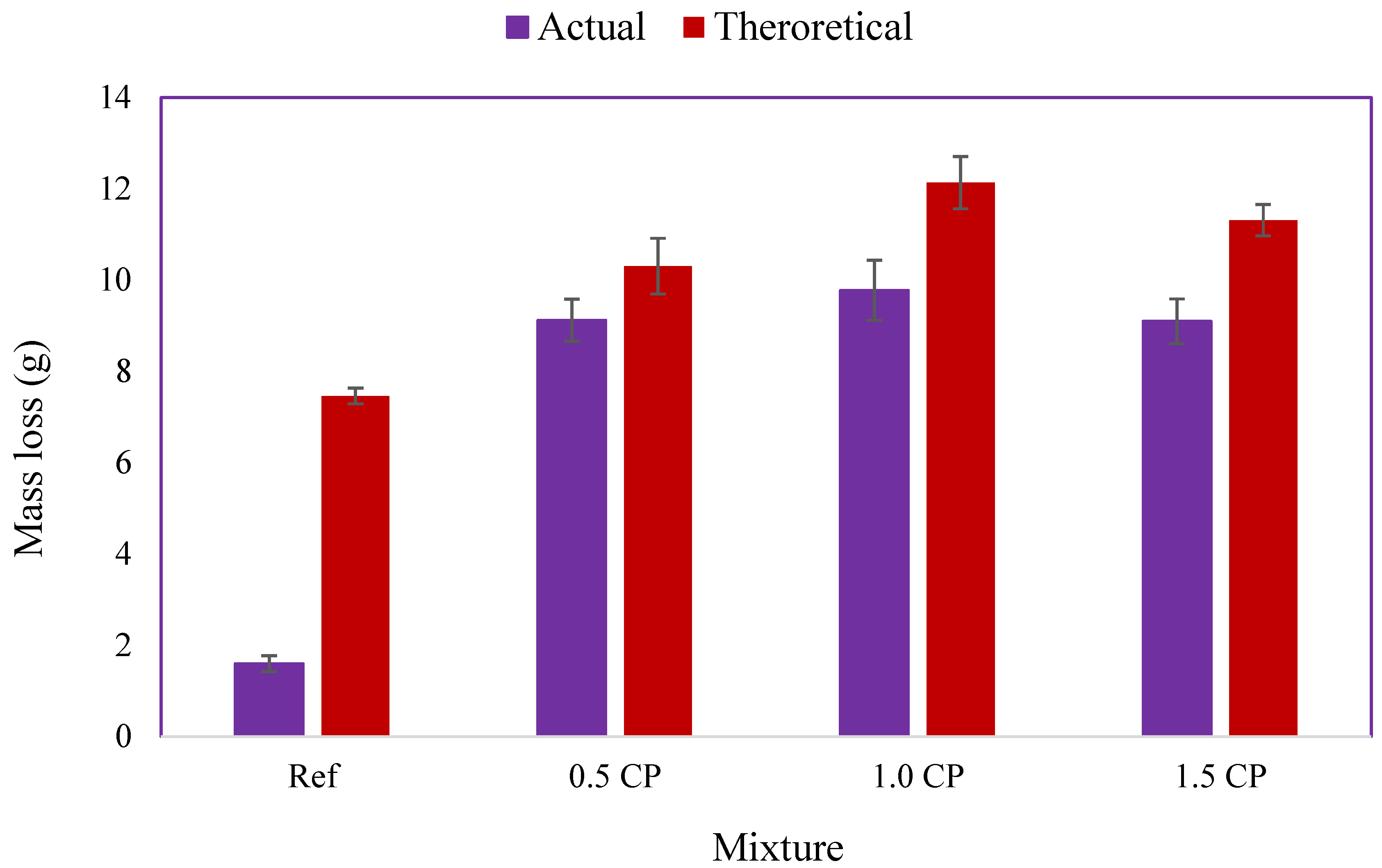
3.1.3. Rebar Mass Loss

Figure 4 shows pictorial images of steel reinforcement bars extracted from mortar specimens at the end of the accelerated corrosion test. Increasing levels of localized and non-uniform loss of the rebar section as the CP content of mixtures became higher are evident in Figure 4b–d. Non-uniform corrosion of reinforcement bars exposed to accelerated corrosion processes is not new, it has been reported in previous studies [45,46]. Research findings by Chen et al. [46] indicated that the non-uniformity of rebar corrosion became pronounced with time. They attributed this to the variation in the oxygen concentration around the rebar. Note that Sides 1 and 2 of the steel rebar in this discussion refer to the two opposite semi-perimeters of the rebar. The increased loss of section on Side 1 of the embedded reinforcement bars highlighted in Figure 4b–d is due to the proximity of the cracked reinforcement bar cover. Hence, the Side 1 rebar semi-perimeter adjacent to the crack was subjected to a higher degree of corrosion activity on account of the huge influx of rebar corrosion accelerants (oxygen, moisture, and chlorides) over time.
Conversely, it is also apparent from Figure 4a that without admixed chloride in the mortar, and the absence of a cracked cover, the corrosion of reinforcement bars embedded in the Ref mortar was infinitesimal and uniform. Although images of Side 2 of the rebars are not shown due to space constraints, some observations were made. First, Sides 1 and 2 of the rebar embedded in the Ref mortar were very similar. This is traceable to the invariable concentration of corrosion accelerants around the rebar. On the other hand, corrosion activity on Side 2 of the reinforcement bars embedded in CP-modified mixtures was small and less variable compared to Side 1. Nonetheless, a gradual increase in corrosion activity on Side 2 of reinforcement bars as the CP dosage in the mortar became higher was detected
Average mass losses of steel reinforcement bars after the accelerated corrosion test are shown in Figure 5. The theoretical rebar losses calculated were 7.5 g for the rebar embedded in the Ref mortar and 10.3–12.1 g for reinforcement bars embedded in CP-modified mortar mixtures. However, the actual gravimetric mass loss measured was 1.6 g for the rebar embedded in the uncracked Ref mortar specimen, 9.1 g for the 0.5 CP rebar, 9.8 g for the 1.0 CP rebar, and 9.1 g for the 1.5 CP rebar. Compared to the Ref mortar rebar, a substantial increase in the mass loss of reinforcements embedded in CP-modified mortar mixtures is very apparent. Surprisingly, there was only a marginal increase in rebar mass loss as the CP dosage in mortar increased from 0.5% to 1.5%. This implies that once a crack was initiated in specimens, the actual effect of CP dosages on rebar corrosion and mass loss was subsumed by the inflow of chlorides through the cracked rebar cover.
The discrepancy between the theoretical and the experimental mass loss highlighted in Figure 5 is not unusual; it has been reported in previous accelerated corrosion studies [45,46]. According to Austin et al. [45], the overestimation of Faraday’s rebar mass loss model is largely caused by two oversights. The first is the use of the total test duration instead of the elapsed time between rebar de-passivation and test termination in the mass loss calculation. The second is that the actual/effective corrosion energy is the energy utilized in the corroding section of a rebar rather than the energy supplied to the entire embedded rebar. This postulation was re-affirmed in a recent report by Hong et al. [34], which reported that the huge amount of energy consumed in the water splitting reaction during the pre-crack corrosion stage created a lot of inefficiency in the accelerated corrosion test. This inefficiency is the reason for the huge difference in actual and theoretical mass losses observed for the rebar embedded in the un-cracked Ref mortar. Although the increased mass loss of reinforcements embedded in CP-modified mixtures was anticipated given the higher current values measured and the early cracking of all the CP-blended specimens, the deviation in the mass loss trend observed for the 1.5 CP reinforcement was unexpected. It is also surprising that, contrary to the recent findings of the authors in a related study [47], the reduced sorptivity of CP-modified mixtures did not translate to enhanced protection of steel rebars against chloride corrosion. Apparently, the presence of CP-borne chlorides in the pore solution prior to the immersion of specimens in the 5% NaCl test solution was more debilitating compared to the influence of externally transported chlorides.

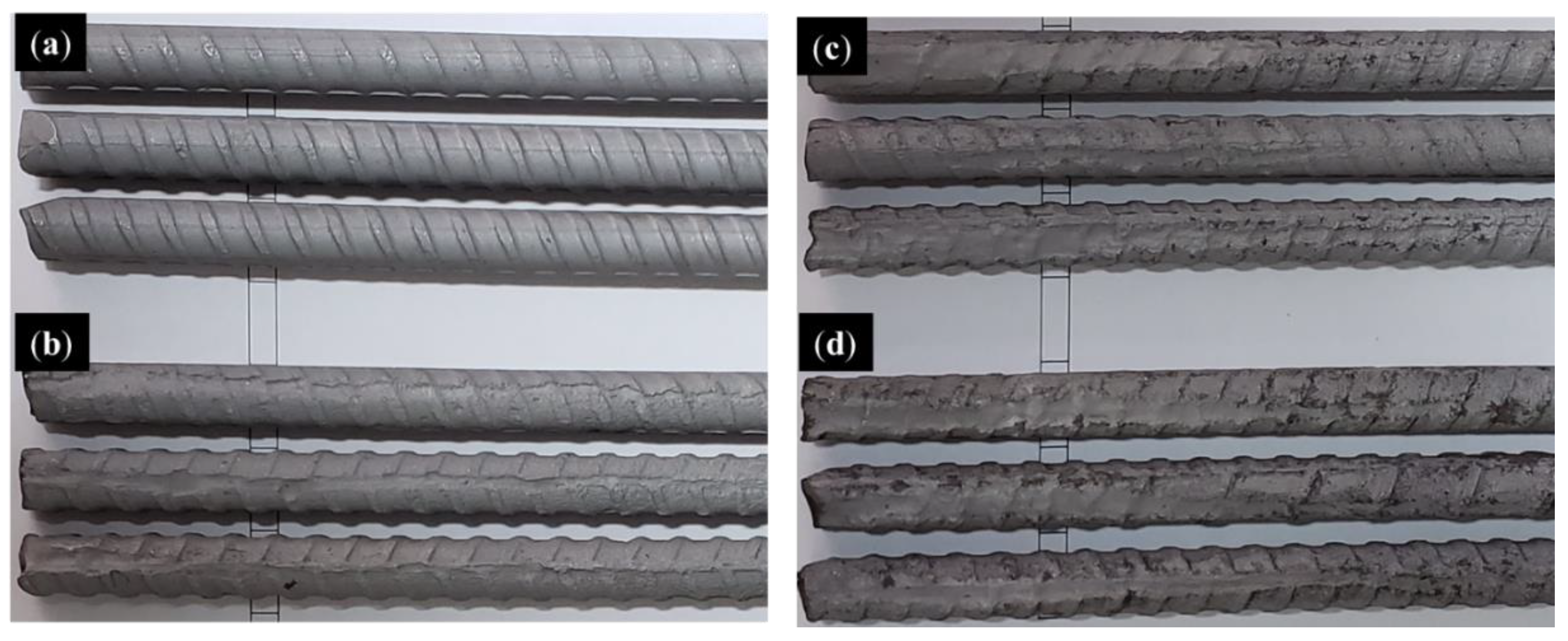
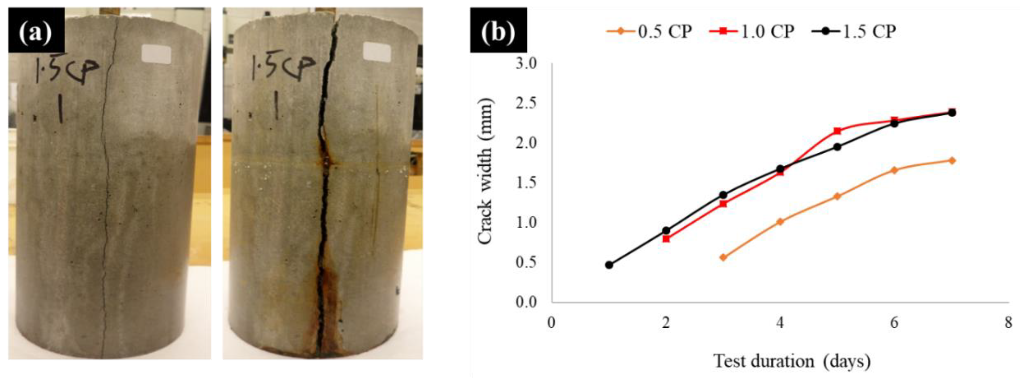
3.1.4. Crack Analyses

A typical example of specimen cracking and surface crack propagation over time is shown in Figure 6a. The average crack width evolution as the accelerated corrosion test progressed is also shown in Figure 6b. Whereas no crack was observed in the plain Ref mortar specimens, a longitudinal crack with an average maximum width of 0.47 mm was initiated in 1.5 CP specimens on the first day of the test. By the second day, the generation of a substantial volume of corrosion byproducts on the steel rebar embedded in the 1.0 CP mortar led to the formation of a micro-crack, 0.80 mm wide. It took about three days for a micro-crack with a maximum width of 0.56 mm to be observed in the 0.5 CP specimens. The crack opening trend for CP-modified specimens seemed to have occurred in two stages. While crack widening in the first six days was almost linear, thereafter, crack opening reduced considerably for all the specimens. The width of the surface crack on specimens at the end of the accelerated corrosion test was 0 for the Ref mortar, 1.78 mm for 0.5 CP, 2.39 mm for 1.0 CP, and 2.38 mm for 1.5 CP.
Cover crack width evolution was dependent on the volume of corrosion byproducts generated and the initial width of cracks formed. Therefore, the tendency of the chloride contained in CP to expedite the accelerated corrosion process, shortening the corrosion and micro-crack initiation time, has two opposing effects. First, as previously mentioned, rapid rise in the volume of corrosion byproducts as the CP dosage in mixtures increased led to an early build-up of expansive pressure and propagation of micro-cracks towards the rebar cover surface. However, the effect of the increased volume of corrosion byproducts and the associated expansive pressure on the widening of cracks is also influenced by the initial width of the cover crack, as highlighted in Figure 6b.
Thus, for smaller-sized crack formed at the very early stage of the corrosion test, the availability of a large volume of corrosion byproducts would partly fill the crack over time, creating an insulating barrier. With the occurrence of this, the corrosion process would not only reduce, but also expansive pressure and crack widening would slightly decrease. Although the erosion and detachment of the consolidated byproduct layer on the rebar surface and the unclogging of cracks with time could rejuvenate the corrosion and crack widening process, there is no evidence suggesting that this occurred in the CP-modified specimens. On the contrary, the reduced rebar mass loss and crack width of the 1.5 CP specimen in comparison to those of the 1.0 CP specimen highlighted in Figure 5 and Figure 6b suggest that the corrosion byproduct layer on the rebar embedded in the 1.5 CP specimen and the clogged crack might have remained intact. Thus, acting as an insulating layer, mitigating further rebar corrosion and cover crack widening.

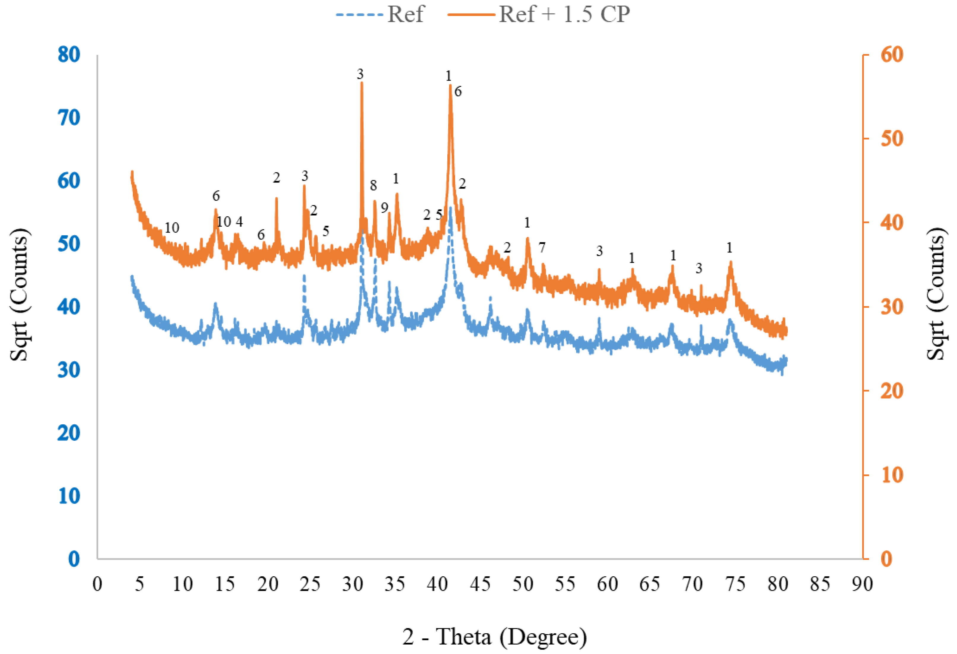
3.1.5. Corrosion Byproduct Phase Composition

The specific volumes of oxide and oxyhydroxide phases found in steel corrosion byproducts are approximately 1.7–6.3 times greater than those of an uncorroded steel bar [48]. This implies that variations in the phase composition and porosity of corrosion byproducts could impact the generation of expansive pressure and crack propagation in the rebar cover. Figure 7 shows the XRD patterns of rust residue obtained from the steel bar embedded in the Ref and 1.5 CP-modified mortar mixtures. Amorphous material highlighted as large humps in the middle of the XRD patterns and traces of rock phases such as quartz, albite, and clinochlore that are probably artifacts from the fine aggregate are evident in the diffractograms shown in Figure 7. However, the main expansive corrosion byproduct phases shown in Figure 7 are iron (III) oxyhydroxides; akaganeite (β-FeOOH), goethite (α-FeOOH), and lepidocrocite (γ-FeOOH) and iron oxides; magnetite (Fe3O4) and hematite (α-Fe2O3). A semi-quantitative phase analysis by Rietveld refinement was also performed, and the results for the iron phases, which constitute about 66–68 wt% of all the phases identified, are presented in Table 4.
The presence of the iron phases shown in Figure 7 and Table 4 is not a surprise given that they have been previously observed as constituents of rebar corrosion residue found in concrete [49,50]. The mechanism of rebar corrosion byproduct formation in cement composites is complicated and varied. Nonetheless, for the chloride-induced steel rebar corrosion investigated in the present study, interactions between chloride, iron, and hydroxyl ions led to the formation of ferrous chloride (FeCl2) and ferrous hydroxide Fe(OH)2 as typical precursors, and depending on the concentration of oxygen, moisture, pH, and dissolved iron, Fe(OH)2 was further oxidized to other iron phases.
Besides indicating that the dominant iron oxide and oxyhydroxide phases found in the Ref and Ref + 1.5 CP rebar corrosion byproducts were magnetite and α-FeOOH/β-FeOOH, respectively, the information shown in Table 4 also suggests a significant degree of similarity in the phase composition. Apparently, with the use of the 5% NaCl solution in the accelerated test, whatever influence the presence of a small dosage of CaCl2 in 1.5% CP would have had on the corrosion byproduct formation was subsumed and masked by the preponderance of chloride ions that permeated from the NaCl test solution. Of course, the similarity in the phase composition does not negate the fact that increased corrosion of the steel rebar embedded in the Ref + 1.5 CP mortar generated a larger volume of corrosion byproducts (depicted as mass loss), as previously highlighted in Figure 5.

3.2. Acid Resistance

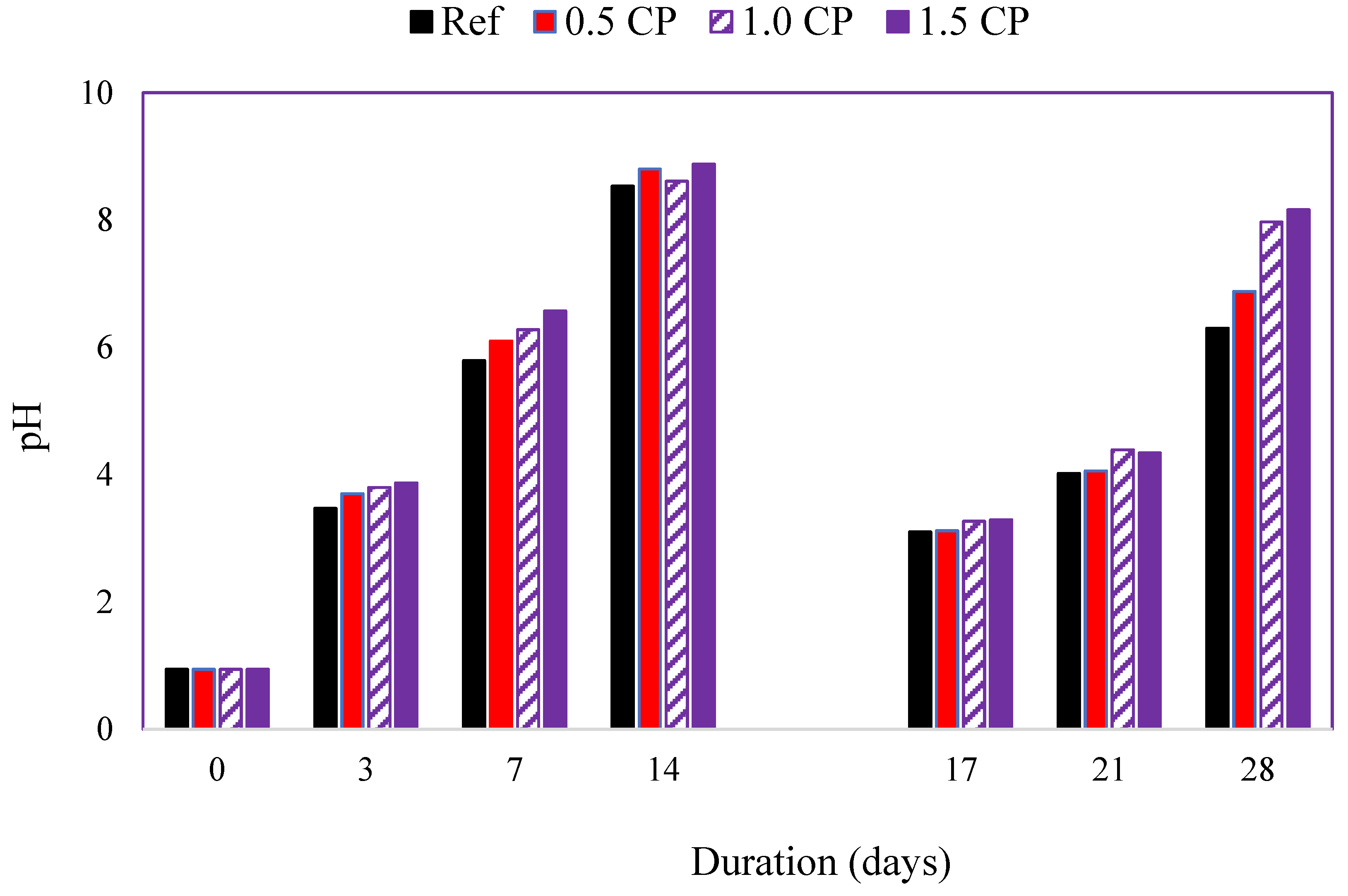
3.2.1. Test Solution pH

Changes in the pH of the HCl test solution over time are shown in Figure 8. After the first 7 days of specimen immersion, the pH increased from approximately 0.9 to 5.8 for Ref, 6.1 for 0.5 CP, 6.3 for 1.0 CP, and 6.6 for 1.5 CP. Although a general increase in the pH of all the test solutions was expected, the slightly higher values of the test solutions containing CP-modified mortar specimens were surprising. The general increase in the alkalinity of the HCl test solution is traced to the continuous dissolution and leaching of portlandite, calcium, and other hydrates from the specimens [51,52]. These leachates gradually transformed the pH of acid test solutions from highly acidic to different milder degrees of acidity and alkalinity over time. Similar increases in the pH of the HCl acid solution containing cement paste and mortar specimens over time have also been reported in the past [53,54]. Although the pH of test solutions continued to increase between 7 and 14 days of specimen immersion, there was no distinct pH trend. This is most likely a result of the reduced corrosiveness of the acid solution and non-uniform depletion of hydrates from the already decalcified surface of the specimens. Despite the change in test solutions at the end of the first 14 days, the test solution pH trend at 21 days remained ill-defined. However, by the 28th day, the acid attack had progressed into the intact, inner area of the specimens. Hence, with the increased dissolution of cement hydrates, and a concomitant rise in pH, a distinct pH trend was observed. The measured pH values at 28 days were 6.3 for Ref, 6.9 for 0.5 CP, 8.0 for 1.0 CP, and 8.2 for 1.5 CP.
For acid solutions containing CP-modified specimens, the higher level of alkalinity observed is attributed to the elevated OH ion content of these specimens. Larbi and Bijen [55] reported that in cement paste modified using a chloride-bearing polymer, OH ions from the pore solution adsorb on polymer particles. It is suspected that the release of these OH ions from polymer particles in CP-modified specimens into the test solution might have occurred in the present study. Therefore, the corresponding rise in the test solution alkalinity as the CP content of specimens increased is understandable. These pH results imply that relative to the Ref mortar, leachates from CP-modified specimens would slightly ameliorate the severity of the acid attack.

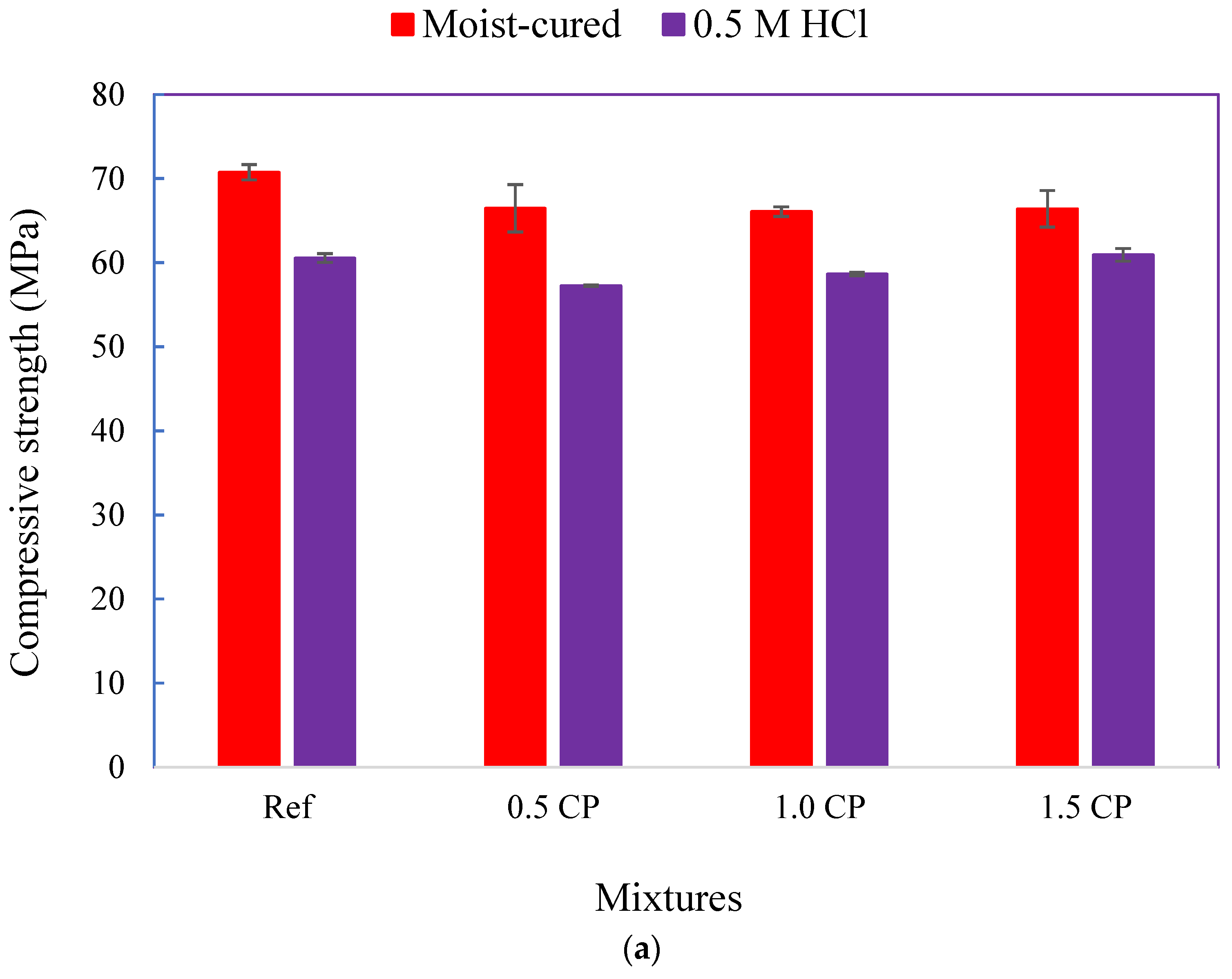
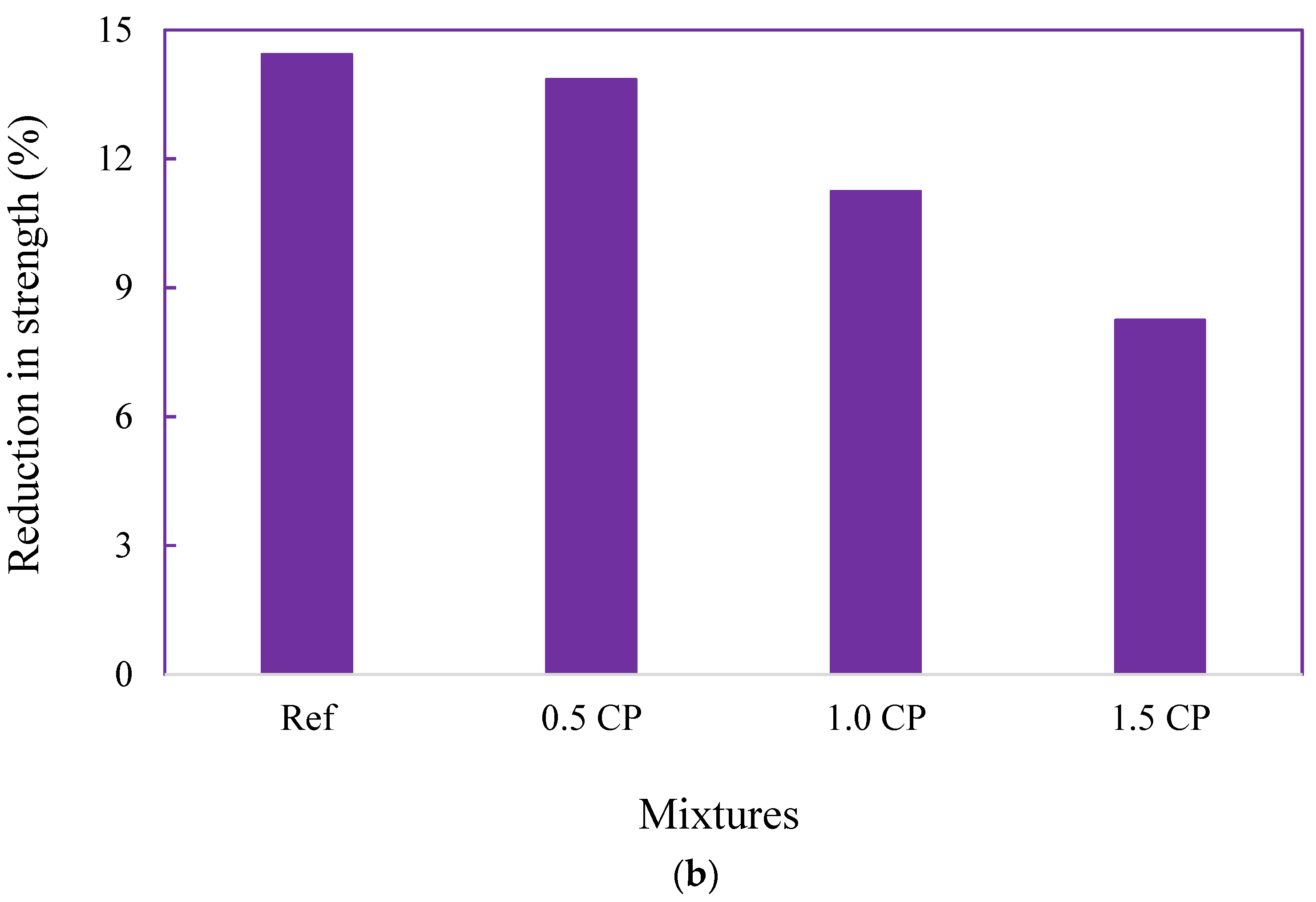
3.2.2. Changes in Compressive Strength

Variations in the compressive strengths of specimens exposed to moist curing and the HCl test solution for 28 days are highlighted in Figure 9a. While the average 28-day moist-cured compressive strengths of mortar mixtures were 71.0 MPa for the Ref and 66.5 MPa for the CP-modified mixtures, the residual strength of all specimens after acid exposure ranged from 57.4 to 60.9 MPa. Relative to the moist-cured specimens, Figure 9b shows that the reduction in the compressive strength of the acid-attacked specimen was 14.4% for the Ref mortar, 13.9% for the 0.5 CP mortar, 11.2% for the 1.0 CP mortar, and 8.2% for the 1.5 CP mortar. Some of the inferences drawn from these results are as follows: First, acid attack-induced strength loss was generally small for all the mixtures. This is partly traced to the limited surface area-to-volume ratio of the 50 mm3 test cubes. Hence, relative to the standard prisms typically used for mortar durability studies, the specimen surface area subjected to acid attack was lower. Moreover, the continued hydration of specimens and the associated microstructure development, while immersed in the acid solution, may have also contributed to the reduced deterioration. Nonetheless, the data in Figure 9a,b suggest that the addition of 1.0–1.5% CP to mortar could potentially enhance its acid attack resistance.
Volume change and swelling of the polymer film in a moist environment have been reported as inimical to the mechanical strength of wet-stored polymer-modified mortars [56]. Therefore, it is quite interesting that although CP-modified specimens were continuously exposed to moisture, specimen resistance to acid attack appears superior to that of the plain Ref mortar. Polymeric film sealing and the refinement of the ITZ between aggregates and the cement paste are well-established attributes of polymer-modified cement composites [57,58]. However, it is believed that, in the present study, the reduced water sorptivity of the CP-blended mixtures (Table 3) and the tendency of CP to alkalinize the test solution worked together in mitigating the microstructure-debilitating acid attack and strength loss. Research findings from studies on the acid attack resistance of polymer-modified cement composites have been contradictory. Whereas some previous studies [17,18,59] showed enhanced resistance, another study [19] highlighted contrary results notwithstanding that a large dosage of an acrylic/styrene-based polymer was utilized. Therefore, it is quite encouraging that despite the very small dosages of the CP utilized in the present study, improvements in acid attack resistance were still observed. Making the present results more interesting is the fact that even though higher dosages of acrylic polymer emulsions could enhance the acid resistance of cement composites, they also created problems such as set retardation, significant air entrainment necessitating the use of defoamers, and a reduced strength of moist-cured specimens. Therefore, the possibility of using very small dosages of CP to enhance the acid attack resistance of unreinforced cement composites such as gravity dam mass concrete, slab-on-grade, and industrial floors is a positive development.

4. Conclusions

This study investigated whether the previously observed positive benefits of CaCl2-blended acrylic polymer (CP) on some durability properties of cement composites [21,22] could be extended to the steel rebar corrosion protection and acid attack resistance of cement mortars. The following conclusions were drawn:
Half-cell potential measurements and accelerated corrosion test results indicate that the addition of CaCl2-blended acrylic polymer to mortar mixtures expedited rebar corrosion initiation and propagation. Consequently, surface cracking occurred early and only on the CP-modified specimens. Crack occurrence was first observed in the 1.5 CP specimen, then sequentially on the 1.0 CP and 0.5 CP specimens.
Compared to the corroded reinforcement bars extracted from the plain Ref mortar, corrosion-induced mass losses of steel reinforcement bars embedded in CP-modified mortars were higher.
X-ray diffraction analyses indicated a huge similarity in corrosion byproduct phases obtained from the steel rebar embedded in the Ref and 1.5 CP-modified mortar mixtures. These phases were akaganeite, goethite, hematite, lepidocrocite, and magnetite.
Conversely, resistance to hydrochloric acid attack evaluated via compressive strength changes over time became higher as the CP dosage of the mortar increased from 1.0% to 1.5%.
Although the present research findings suggest that CP should not be used as a chemical admixture in steel rebar-reinforced cement composites, it could be used as an admixture in unreinforced applications such as gravity dam mass concrete, rigid pavement, pedestrian walkways, and industrial floors routinely exposed to chemical attacks.

Author Contributions

Conceptualization, O.O. and N.B.; methodology, O.O.; validation, O.O. and N.B.; formal analysis, O.O.; investigation, O.O.; resources, N.B.; data curation, O.O.; writing—original draft preparation, O.O.; writing—review and editing, O.O. and N.B.; supervision, N.B.; project administration, N.B. All authors have read and agreed to the published version of the manuscript.

Funding

This research received no external funding.

Institutional Review Board Statement

Not applicable.

Informed Consent Statement

Not applicable.

Data Availability Statement

The data presented in this study are available on request from the corresponding author.

Acknowledgments

The authors extend their appreciation to the Polymerpave Global Corporation for providing the CaCl2-blended acrylic polymer emulsion used in this study.

Conflicts of Interest

The authors declare no conflict of interest.

References

  1. British Standard European Norm (BS EN) 206-1; Concrete—Part 1: Specification, Performance, Production and Conformity. European Committee for Standardization (CEN): Brussels, Belgium, 2013.
  2. American Concrete Institute (ACI) 318; Building Code Requirements for Structural Concrete and Commentary. ACI: Detroit, MI, USA, 2019.
  3. Andrade, C.; Page, C.L. Pore solution chemistry and corrosion in hydrated cement systems containing chloride salts. A study of cation specific effects. Br. Corros. J. 1986, 21, 49–54. [Google Scholar] [CrossRef]
  4. Pruckner, F.; Gjørv, O.E. Effect of CaCl2 and NaCl additions on concrete corrosivity. Cem. Concr. Res. 2004, 34, 1209–1217. [Google Scholar] [CrossRef]
  5. Xu, J.; Jiang, L.; Wang, W.; Jiang, Y. Influence of CaCl2 and NaCl from different sources on chloride threshold value for the corrosion of steel reinforcement in concrete. Constr. Build. Mater. 2011, 25, 663–669. [Google Scholar] [CrossRef]
  6. Delagrave, A.; Marchand, J.; Ollivier, J.-P.; Julien, S.; Hazrati, K. Chloride binding capacity of various hydrated cement paste systems. Adv. Cem. Based Mater. 1997, 6, 28–35. [Google Scholar] [CrossRef]
  7. Zhu, Q.; Jiang, L.; Chen, Y.; Xu, J.; Mo, L. Effect of chloride salt type on chloride binding behavior of concrete. Constr. Build. Mater. 2012, 37, 512–517. [Google Scholar] [CrossRef]
  8. De Weerdt, K.; Colombo, A.; Coppola, L.; Justnes, H.; Geiker, M. Impact of the associated cation on chloride binding of Portland cement paste. Cem. Concr. Res. 2015, 68, 196–202. [Google Scholar] [CrossRef]
  9. Shi, Z.; Geiker, M.R.; De Weerdt, K.; Østnor, T.A.; Lothenbach, B.; Winnefeld, B.; Skibsted, J. Role of calcium on chloride binding in hydrated Portland cement–metakaolin–limestone blends. Cem. Concr. Res. 2017, 95, 205–216. [Google Scholar] [CrossRef]
  10. Page, C.L.; Vennesland, O. Pore solution composition and chloride binding capacity of silica-fume cement pastes. Mater. Struct. 1983, 16, 19–25. [Google Scholar] [CrossRef]
  11. Arya, C.; Buenfeld, N.R.; Newman, J.B. Factors influencing chloride binding in concrete. Cem. Concr. Res. 1990, 20, 291–300. [Google Scholar] [CrossRef]
  12. Manera, M.; Vennesland, O.; Bertolini, L. Chloride threshold for rebar corrosion in concrete with addition of silica fume. Corros. Sci. 2008, 50, 554–560. [Google Scholar] [CrossRef]
  13. Hou, J.; Chung, D.D.L. Effect of admixture in concrete on the corrosion resistance of steel reinforced concrete. Corros. Sci. 2000, 42, 1489–1507. [Google Scholar] [CrossRef]
  14. Dotto, J.M.R.; De Abreu, A.G.; Dal Molin, D.C.C.; Müller, I.L. Influence of silica fume addition on concretes physical properties and on corrosion behaviour of reinforcement bars. Cem. Concr. Compos. 2004, 26, 31–39. [Google Scholar] [CrossRef]
  15. Kelestemur, O.; Demirel, B. Corrosion behavior of reinforcing steel embedded in concrete produced with finely ground pumice and silica fume. Constr. Build. Mater. 2010, 24, 1898–1905. [Google Scholar] [CrossRef] [Green Version]
  16. American Society of Concrete Contractors (ASCC). Position Statement #31—Acceptable Use of Calcium Chloride in Concrete. Retrieved on 16 March 2019. 2020. Available online: https://www.ascconline.org/Portals/0/docs/POSITION-STATEMENTS/PS-31-acceptable-use-calcium-chloride-concrete.pdf (accessed on 14 January 2022).
  17. Shaker, F.A.; El-Dieb, A.S.; Reda, M.M. Durability of styrene butadiene latex modified concrete. Cem. Concr. Res. 1997, 27, 711–720. [Google Scholar] [CrossRef]
  18. Rossignolo, J.A.; Agnesini, M.V. Durability of polymer-modified lightweight aggregate concrete. Cem. Concr. Compos. 2004, 26, 375–380. [Google Scholar] [CrossRef]
  19. Sokolova, I. Corrosion resistance of steel reinforcement in polymer silicate shyngizite concrete. E3S Web Conf. 2020, 164, 02032. [Google Scholar] [CrossRef]
  20. Monteny, J.; Belie, N.; Vincke, E.; Verstraete, W.; Taerwe, L. Chemical and microbiological tests to simulate sulphuric acid corrosion of polymer-modified concrete. Cem. Concr. Res. 2001, 31, 1359–1365. [Google Scholar] [CrossRef]
  21. Pacheco-Torgal, F.; Jalali, S. Sulphuric acid resistance of plain, polymer modified, and fly ash cement concretes. Constr. Build. Mater. 2009, 23, 3485–3491. [Google Scholar] [CrossRef] [Green Version]
  22. Onuaguluchi, O.; Ratu, R.; Banthia, N. The effects of CaCl2-blended acrylic polymer emulsion on the properties of cement mortar. Mater. Struct. 2018, 51, 50. [Google Scholar] [CrossRef]
  23. Onuaguluchi, O.; Banthia, N. Alkali-silica reaction resistance of cementitious material containing CaCl2-blended acrylic polymer emulsion. J. Mater. Civil. Eng. 2020, 33, 04019378. [Google Scholar] [CrossRef]
  24. American Society of Testing and Materials (ASTM) C305; Standard Practice for Mechanical Mixing of Hydraulic Cement Pastes and Mortars of Plastic Consistency. ASTM International: West Conshohocken, PA, USA, 2014.
  25. ASTM A276; Standard Specifications for Stainless Steel Bars and Shapes. ASTM International: West Conshohocken, PA, USA, 2017.
  26. Schneider, C.A.; Rasband, W.S.; Eliceiri, K.W. NIH Image to ImageJ: 25 years of image analysis. Nat. Methods 2012, 9, 671–675. [Google Scholar] [CrossRef]
  27. ASTM G1-03; Standard Practice for Preparing, Cleaning and Evaluating Corrosion Test Specimens. ASTM International: West Conshohocken, PA, USA, 2017.
  28. ASTM C876; Standard Test Method for Corrosion Potentials of Uncoated Reinforcing Steel in Concrete. ASTM International: West Conshohocken, PA, USA, 2015.
  29. García-Alonso, M.C.; Escudero, M.L.; Miranda, J.M.; Vega, M.I.; Capilla, F.; Correia, M.J.; Salta, M.; Bennani, A.; González, J.A. Corrosion behaviour of new stainless steels reinforcing bars embedded in concrete. Cem. Concr. Res. 2007, 37, 1463–1471. [Google Scholar] [CrossRef] [Green Version]
  30. Uthaman, S.; George, R.P.; Vishwakarma, V.; Harilal, M.; Philip, J. Enhanced seawater corrosion resistance of reinforcement in nanophase modified fly ash concrete. Constr. Build. Mater. 2019, 221, 232–243. [Google Scholar] [CrossRef]
  31. Addari, D.; Elsener, B.; Rossi, A. Electrochemistry and surface chemistry of stainless steels in alkaline media simulating concrete pore solutions. Electrochim. Acta 2008, 53, 8078–8086. [Google Scholar] [CrossRef]
  32. Ouglova, A.; Raharinaivo, A.; Berthaud, Y.; Petre-Lazar, I.; Boukhenhouf, H. Numerical simulation of potential distribution to the corrosion of reinforcement in concrete structures. Mater. Struct. 2005, 38, 711–719. [Google Scholar] [CrossRef]
  33. Gonzales, J.A.; Otero, E.; Feliu, S.; Lopez, W. Initial steps of corrosion in the steel/Ca(OH)2 + Cl system: The role of heterogeneities on the steel surface and oxygen supply. Cem. Concr. Res. 1993, 23, 33–40. [Google Scholar] [CrossRef]
  34. Idriss, A.F.; Negi, S.C.; Jofriet, J.C.; Hayward, G.I. Effect of hydrogen sulphide emissions on cement mortar specimens. Can. Biosyst. Eng. 2001, 43, 5.23–5.28. [Google Scholar]
  35. Hong, S.; Zheng, F.; Shi, G.; Li, J.; Luo, X.; Xing, F.; Tang, L.; Dong, B. Determination of impressed current efficiency during accelerated corrosion of reinforcement. Cem. Concr. Compos. 2020, 108, 103536. [Google Scholar] [CrossRef]
  36. Goñi, S.; Andrade, C. Synthetic concrete pore solution chemistry and rebar corrosion rate in the presence of chlorides. Cem. Concr. Res. 1990, 20, 525–539. [Google Scholar] [CrossRef]
  37. Enevoldsen, J.N.; Hansson, C.M.; Hope, B.B. The influence of internal relative humidity on the rate of corrosion of steel embedded in concrete and mortar. Cem. Concr. Res. 1994, 24, 1373–1382. [Google Scholar] [CrossRef]
  38. Kim, J.-H.; Robertson, R.E. Effects of polyvinyl alcohol on aggregate-paste bond strength and the interfacial transition zone. Adv. Cem. Based Mater. 1998, 8, 66–76. [Google Scholar] [CrossRef]
  39. Caré, S.; Raharinaivo, A. Influence of impressed current on the initiation of damage in reinforced mortar due to the corrosion of embedded steel. Cem. Concr. Res. 2007, 37, 1598–1612. [Google Scholar] [CrossRef]
  40. Tuutti, K. Corrosion of Steel in Concrete; Swedish Cement and Concrete Research Institute: Stockholm, Sweden, 1982. [Google Scholar]
  41. Alonso, C.; Andrade, C.; Rodriguez, J.; Diez, J.M. Factors Controlling Cracking of Concrete Affected by Reinforcement Corrosion. Mater. Struct. 1998, 31, 435–441. [Google Scholar] [CrossRef]
  42. El Maaddawy, T.A.; Soudki, K.A. Effectiveness of Impressed Current Technique to Simulate Corrosion of Steel Reinforcement in Concrete. J. Mater. Civ. Eng. 2003, 15, 41–47. [Google Scholar] [CrossRef]
  43. Jang, B.S.; Oh, B.H. Effects of non-uniform corrosion on the cracking and service life of reinforced concrete structures. Cem. Concr. Res. 2010, 40, 1441–1450. [Google Scholar] [CrossRef]
  44. Fedosov, S.V.; Rumyantseva, V.E.; Krasilnikov, I.V.; Konovalova, V.S.; Evsyakov, A.S. Mathematical modeling of the colmatation of concrete pores during corrosion. Mag. Civ. Eng. 2018, 83, 198–207. [Google Scholar] [CrossRef]
  45. Wang, X.; Song, X.; Zhang, M.; Du, X. Experimental comparison of corrosion unevenness and expansive cracking between accelerated corrosion methods used in laboratory research. Constr. Build. Mater. 2017, 153, 36–43. [Google Scholar] [CrossRef]
  46. Chen, F.; Li, C.; Baji, H.; Ma, B. Quantification of non-uniform distribution and growth of corrosion products at steel-concrete interface. Constr. Build. Mater. 2020, 237, 117610. [Google Scholar] [CrossRef]
  47. Austin, S.A.; Lyons, R.; Ing, M.J. Electrochemical Behaviour of Steel Reinforced Concrete during Accelerated Corrosion Testing. Corrosion 2004, 60, 203–212. [Google Scholar] [CrossRef]
  48. Onuaguluchi, O.; Banthia, N.; Gourlay KMinhas, G. Moisture transport and steel rebar corrosion in repair composites incorporating Nano-Fibrillated Cellulose (NFC). Constr. Build Mater. 2021, 309, 125154. [Google Scholar] [CrossRef]
  49. Marcotte, T.D. Characterization of Chloride-Induced Corrosion Products that form in Steel-Reinforced Cementitious Materials. Ph.D. Thesis, University of Waterloo, Waterloo, ON, Canada, 2001. [Google Scholar]
  50. Duffo, G.S.; Morris, W.; Raspini, I.; Saragovi, C. A study of steel rebars embedded in concrete during 65 years. Corros. Sci. 2004, 46, 2143–2157. [Google Scholar] [CrossRef]
  51. Chitty, W.-J.; Dillmann, P.; L’Hostis, V.; Lombard, C. Long-term corrosion resistance of metallic reinforcements in concrete—A study of corrosion mechanisms based on archaeological artefacts. Corros. Sci. 2005, 47, 1555–1581. [Google Scholar] [CrossRef]
  52. Paul, S.C.; Babafemi, A.J.; Conradie, K.; van Zijl, G.P.A.G. Applied voltage on corrosion mass loss and cracking behavior of steel-reinforced shcc and mortar specimens. J. Mater. Civ. Eng. 2016, 29, 04016272. [Google Scholar] [CrossRef]
  53. Israel, D.; Macphee, D.; Lachowski, E. Acid attack on pore-reduced cements. J. Mater. Sci. 1997, 32, 4109–4116. [Google Scholar] [CrossRef]
  54. Beddoe, R.E.; Dorner, H.W. Modelling acid attack on concrete: Part I. The essential mechanisms. Cem. Concr. Res. 2005, 35, 2333–2339. [Google Scholar] [CrossRef]
  55. De Ceukelaire, L. The effects of hydrochloric acid on mortar. Cem. Concr. Res. 1992, 22, 903–914. [Google Scholar] [CrossRef]
  56. Larbi, J.A.; Bijen, J.M.J.M. Interaction of polymers with Portland cement during hydration: A study of the chemistry of the pore solution of polymer-modified cement systems. Cem. Concr. Res. 1990, 20, 139–147. [Google Scholar] [CrossRef]
  57. Jenni, A.; Zurbriggen, R.; Holzer, L.; Herwegh, M. Changes in microstructures and physical properties of polymer-modified mortars during wet storage. Cem. Concr. Res. 2006, 36, 79–90. [Google Scholar] [CrossRef]
  58. Beenldens, A.; Monteny, J.; Vincke, E.; De Belie, N.; van Gemert, D.; Taerwe, L. Resistance to biogenic sulphuric acid corrosion of polymer-modified mortars. Cem. Concr. Res. 2001, 23, 47–56. [Google Scholar] [CrossRef]
  59. Rossignolo, J.A. Effect of silica fume and SBR latex on the paste aggregate interfacial transition zone. Mat. Res. 2007, 10, 83–86. [Google Scholar] [CrossRef] [Green Version]
Figure 1. Accelerated corrosion test schematic.
Cmd 03 00009 g001
Figure 2. Half-cell potential measurements.
Cmd 03 00009 g002
Figure 3. (a) Corrosion current density versus time plot. (b) Crack occurrence time.
Cmd 03 00009 g003
Figure 4. Embedded rebar section loss pattern: (a) Ref; (b) 0.5 CP; (c) 1.0 CP; (d) 1.5 CP.
Cmd 03 00009 g004
Figure 5. Reinforcement mass loss.
Cmd 03 00009 g005
Figure 6. (a) Typical surface crack in 1.5 CP specimens after 1d and 7d; (b) crack evolution.
Cmd 03 00009 g006
Figure 7. XRD diffractogram of corrosion byproduct showing: magnetite (1); goethite (2); quartz (3); lepidocrocite (4); hematite (5); akaganeite (6); α-Fe (7); albite low (8); calcite (9); and clinochlore (10).
Cmd 03 00009 g007
Figure 8. pH evolution of the 0.5 M HCl solution.
Cmd 03 00009 g008
Figure 9. (a) Twenty-eight-day compressive strength of specimens exposed to moist curing and 0.5 M HCl solution. (b) Relative reduction in the compressive strength after acid attack.
Cmd 03 00009 g009aCmd 03 00009 g009b
Table 1. Chemical composition of the CaCl2-blended acrylic polymer emulsion.
ItemComposition (%)
Calcium chloride, hydrated10–30
Acrylic copolymer latex10–30
Water30–60
Other<1
pH6–8
Table 2. Chemical composition of the steel rebar.
ElementComposition (%)ElementComposition (%)
Carbon0.28Chromium0.17
Manganese1.10Molybdenum0.02
Phosphorous0.015Copper0.40
Sulfur0.044Vanadium0.02
Silicon0.18Niobium0.002
Nickel0.09Carbon equivalent0.49
Table 3. 14d mechanical strength and transport property of cement mortar mixtures.
MixSplitting Tensile Strength (MPa)Sorptivity (mm/s1/2)
Ref 3.4 ± 0.30.0438 ± 0.0004
0.5 CP3.9 ± 0.20.0413 ± 0.0009
1.0 CP4.0 ± 0.10.0394 ± 0.0010
1.5 CP3.9 ± 0.20.0336 ± 0.0004
Table 4. Composition of expansive iron phases in corrosion residue (wt%).
Iron PhaseRefRef + 1.5 CP
Akaganeite (β-FeOOH)15.014.0
Goethite (α-FeOOH)18.019.0
Hematite (α-Fe2O3)1.01.0
Lepidocrocite (γ-FeOOH)2.02.0
Magnetite (Fe3O4)30.032.0
Publisher’s Note: MDPI stays neutral with regard to jurisdictional claims in published maps and institutional affiliations.

