Article

Impact of Chloride on the Environmentally-Assisted Crack Initiation Behaviour of Low-Alloy Steel under Boiling Water Reactor Conditions

Paul Scherrer Institute (PSI), 5232 Villigen, Switzerland
*
Author to whom correspondence should be addressed.
Corros. Mater. Degrad. 2022, 3(2), 178-191; https://0-doi-org.brum.beds.ac.uk/10.3390/cmd3020010
Submission received: 21 January 2022 / Revised: 22 February 2022 / Accepted: 21 March 2022 / Published: 23 March 2022

Abstract

:
Low-alloy reactor pressure vessel steels have a rather low susceptibility to stress corrosion cracking (SCC) in a boiling water reactor (BWR) environment if the high-temperature water contains no anionic impurities. Recent investigations revealed that under oxidizing BWR normal water chemistry (NWC) conditions extremely small amounts of chloride, can cause very high SCC growth rates in these materials. Therefore, the effect of continuous and temporary chloride additions on the crack initiation behaviour was explored by a series of constant extension rate tensile (CERT) and constant load tests in high-temperature water. In an NWC environment, containing ≥2 ppb of chloride, strain-induced corrosion cracking (SICC) initiation occurred briefly after the onset of plastic yielding and at much smaller strains than in high-purity water. On the other hand, under reducing hydrogen water chemistry conditions with up to 700 ppb chloride, no SICC was detected up to very high strains. CERT experiments, with moderate short-term chloride transients before and during the loading, showed that even serious mechanical loading transients, one day after returning to high-purity water, did not result in early SICC initiation.

1. Introduction

Environmentally-assisted cracking (EAC) of structural materials in the primary circuit of light water reactors is one of the most frequent ageing mechanisms, challenging the economic and safe operation of nuclear power plants. In former research projects at PSI and elsewhere, the EAC behaviour of low-alloy steel (LAS) pressure boundary components has been well established under transient-free, steady-state boiling water reactor (BWR) power operation conditions and revealed very low susceptibility to EAC crack growth under constant load [1,2,3,4,5,6,7]. On the other hand, more recent crack growth investigations at PSI [8,9,10], Framatome GmbH (formerly Areva GmbH) [11,12], and GE-Global Research Center [13,14,15,16] have shown that small amounts of chloride in the simulated (oxygenated) reactor water can cause very high crack growth rates under constant load. Such variations in water chemistry may occasionally occur in nuclear power plants (ion exchanger resin intrusions or condenser leakages during steady-state power operation). Currently, the extent (magnitude, period) and frequency of such variations is strongly minimized, e.g., by following the current BWR water chemistry guidelines of the Electric Power Research Institute (Table 1) [17]. Nevertheless, the possible effect of short-term water chemistry transients on the transition EAC crack growth behaviour during and, in particular, after a transient under subsequent steady-state power operation is of great interest for safety assessments. Therefore, the effect of chloride on the EAC initiation behaviour was further investigated at PSI in the framework of a national research program [18]. In the current paper, the results are briefly summarized, and the paper has been adopted from the project report [18].

2. Materials and Experimental Procedure

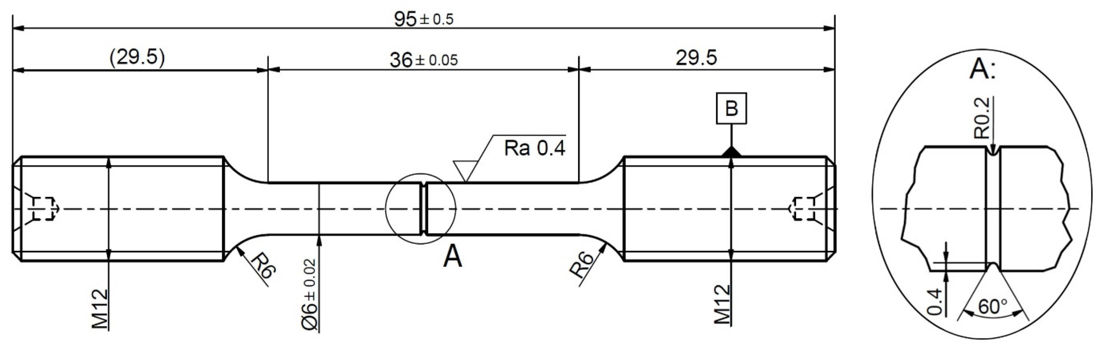
2.1. Material and Specimen

For the EAC initiation tests, a reactor pressure vessel steel (hot-rolled plate) SA 533 B Cl.1 with a sulphur content of 0.018 wt.% was used. The material was quenched and tempered, stress relieved, and had a granular bainitic structure with an average former austenitic grain size of 10 to 20 µm. The spatial distribution and morphology of the MnS inclusions was fairly homogeneous, covering the range from small, spherical, to large (up to a few 100 µm) elongated inclusions. The chemical composition and mechanical properties are shown in Table 2 and Table 3. The tests were performed using round bar tensile specimens fabricated (lathed) in the L-orientation of the hot-rolled plate (a few tests were duplicated with specimens in S- and T-orientation revealing no influence of the orientation on the cracking behaviour) with a V-shaped notch in the centre of the gauge section (Figure 1). This notch was necessary to restrict the distance between the reference electrode and cracking site, which is necessary because the throwing power of the current is very limited in the low-conductivity electrolyte (high-purity water). The surface of the specimen was ground with SiC paper to a surface roughness of Ra ≈ 0.4 µm, and the notch area was investigated in a scanning electron microscope (SEM) before testing it on any pre-existing surface defects. The specimen was electrically insulated from the test facility by ceramic washers.

2.2. Experimental Procedure

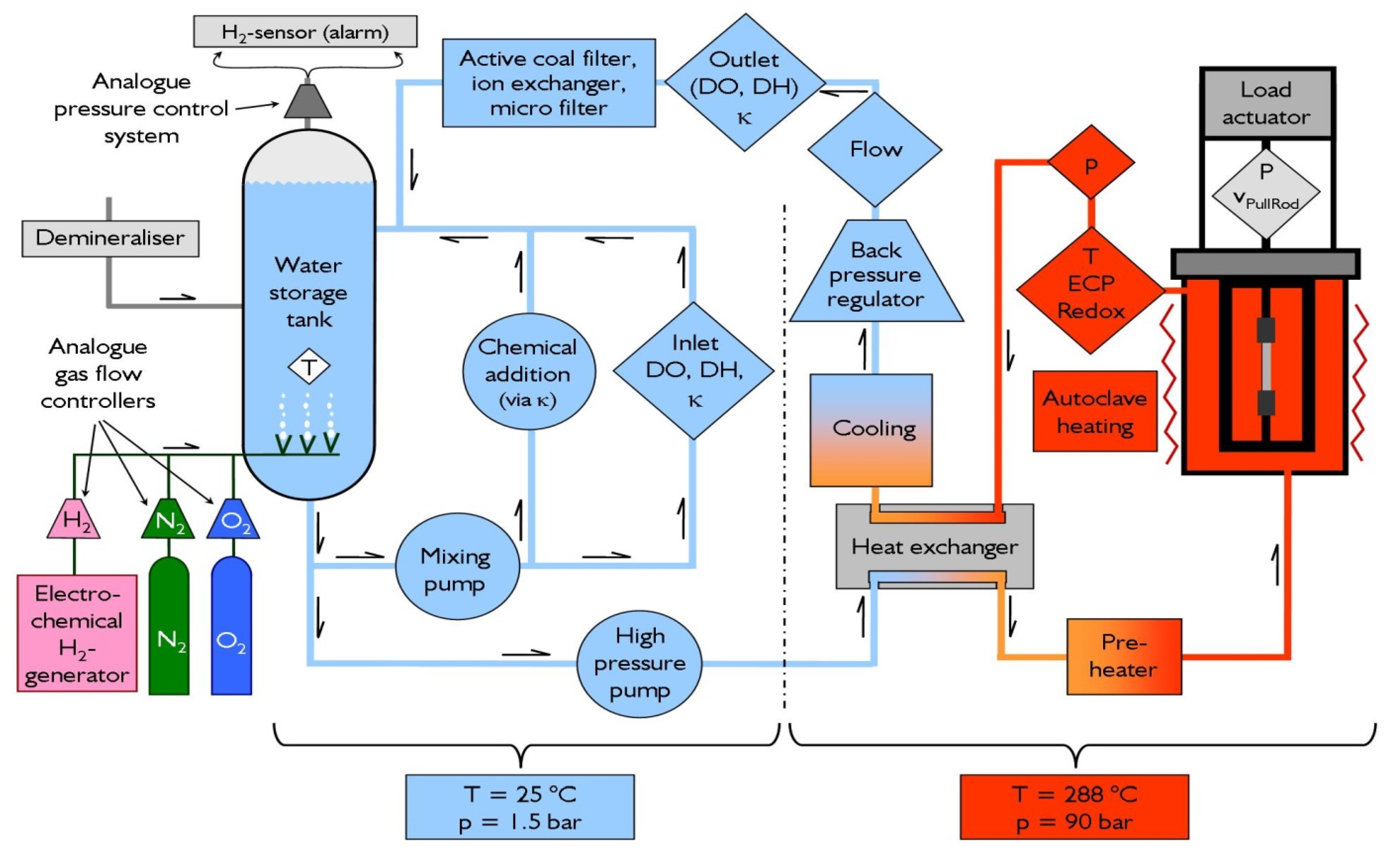
2.2.1. Test Set-Up, Environmental Conditions, and Procedure

To study the EAC initiation behaviour, constant extension rate tensile (CERT) tests, as well as two tests under constant load, were performed in a sophisticated refreshing high-temperature water loop in an autoclave with an electromechanical tensile machine (Figure 2). During the experiments, all important mechanical loading (load, pull rod stroke) and environmental parameters at inlet and outlet (dissolved oxygen (DO), dissolved hydrogen (DH), conductivity, T, p, flow, etc.) were recorded continuously. The electrochemical corrosion potential (ECP) of the specimen and the redox potential (platinum probe) were monitored by use of a Cu/Cu2O ZrO2-membrane reference electrode. The ionic impurities of the water (inlet and outlet) were analysed by inductively coupled plasma–atomic emission spectroscopy (ICP–AES) and ion chromatography (IC) during each test.
BWR/normal water chemistry (NWC) conditions were simulated with high-purity (inlet/outlet conductivity < 0.06/<0.15 µS/cm, ionic impurities < 1 ppb), oxygenated water (DO = 2 ppm, ECP ≈ +110 mVSHE, redox potential ≈ +270 mVSHE) at a temperature of 274 °C. In two cases, hydrogen (DH = 0.15 ppm, ECP = −600 mVSHE, redox potential = −522 mVSHE) was added to simulate a reducing hydrogen water chemistry (HWC) environment.
During each test, the specimen was pre-oxidised in the corresponding environment for one week at a small pre-load of 1 kN (nominal stress ≈ 50 MPa). Afterwards, the specimen was strained at a constant stroke rate of the pull rod (vpull-rod) of 3.6 × 10⁻⁹ m/s, which corresponds to a nominal strain rate of 10−7 s−1. A strain rate in the notch root of the specimen of 2.2 × 10⁻⁶ s−1 was estimated by finite element modelling. The nominal stress was calculated by dividing the actual load by the initial cross section at the notch root. The specimen was unloaded, and the test was finished, either, a few hours after the detection of crack initiation or after reaching the ultimate tensile strength. Two load-controlled experiments were performed by loading the specimen at a rate of 16.7 N/s and then keeping the load constant for the remaining time of the test. Those experiments were finished after 955 or 1746 h of constant load, respectively. After the tests, the specimens were carefully examined in an SEM. In some cases, the in-depth cracking and fracture mode were investigated, and the crack extension was measured by SEM after opening the specimen by mechanical overloading in air at liquid nitrogen temperature.
HCl or NaCl (to reach a chloride content of 2 to 700 ppb) were continuously added (48 h after reaching the test temperature) to the high-purity water in most experiments, controlled by the conductivity of the inlet water, and verified by analysing the water samples from each test. A series of five CERT tests were performed where 20 ppb of chloride were added only for a 96 h period during the test (corresponding to action level 1 of the previous edition of the EPRI water chemistry guidelines [19]). The chloride transient was applied at different periods in time during the CERT tests (see Table 4), which is schematically shown in Figure 3. To avoid crack initiation during the initial loading phase in the two constant load experiments, chloride addition (20 ppb) started just after reaching the final load level in the case of the first test and slightly earlier in the second test.

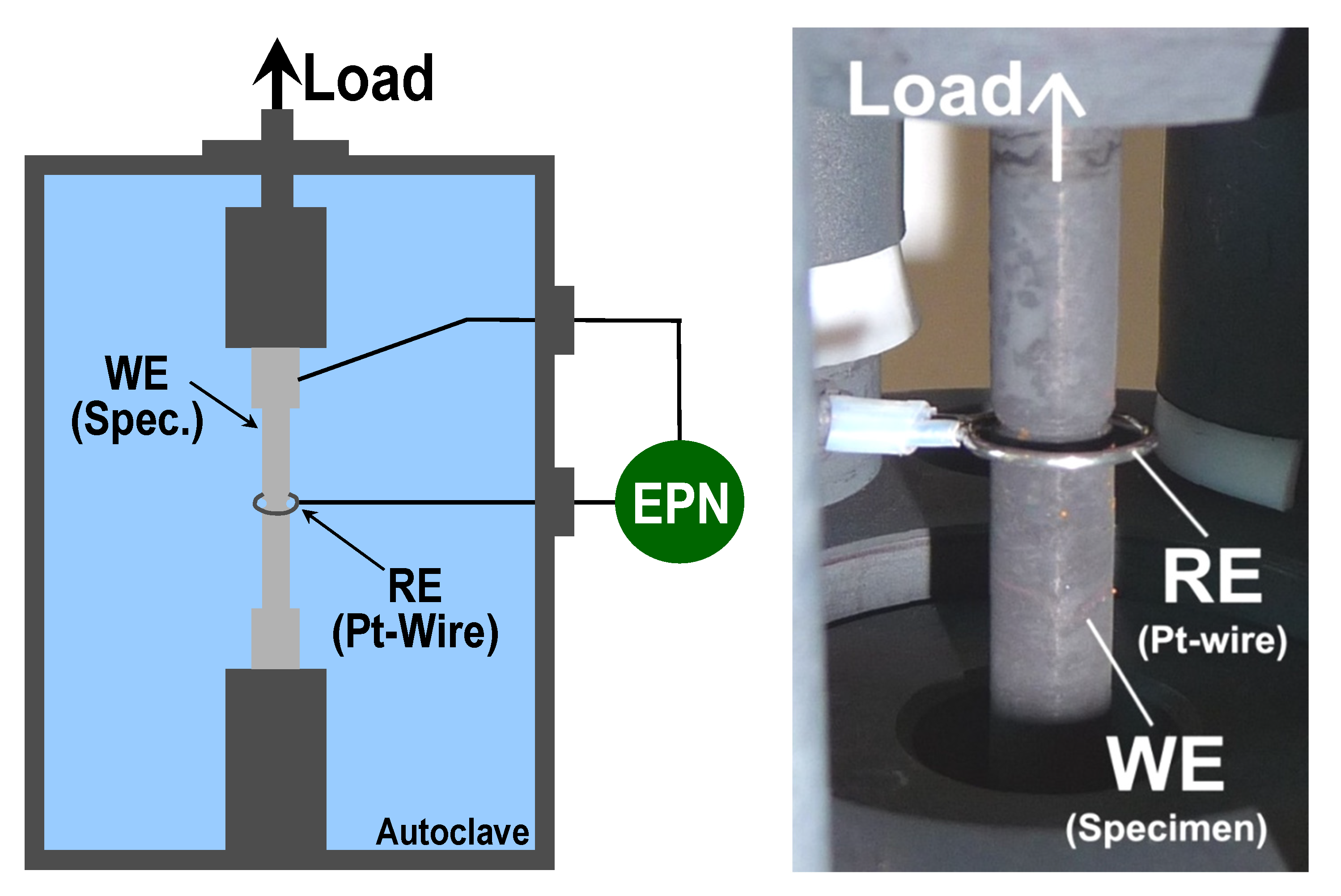
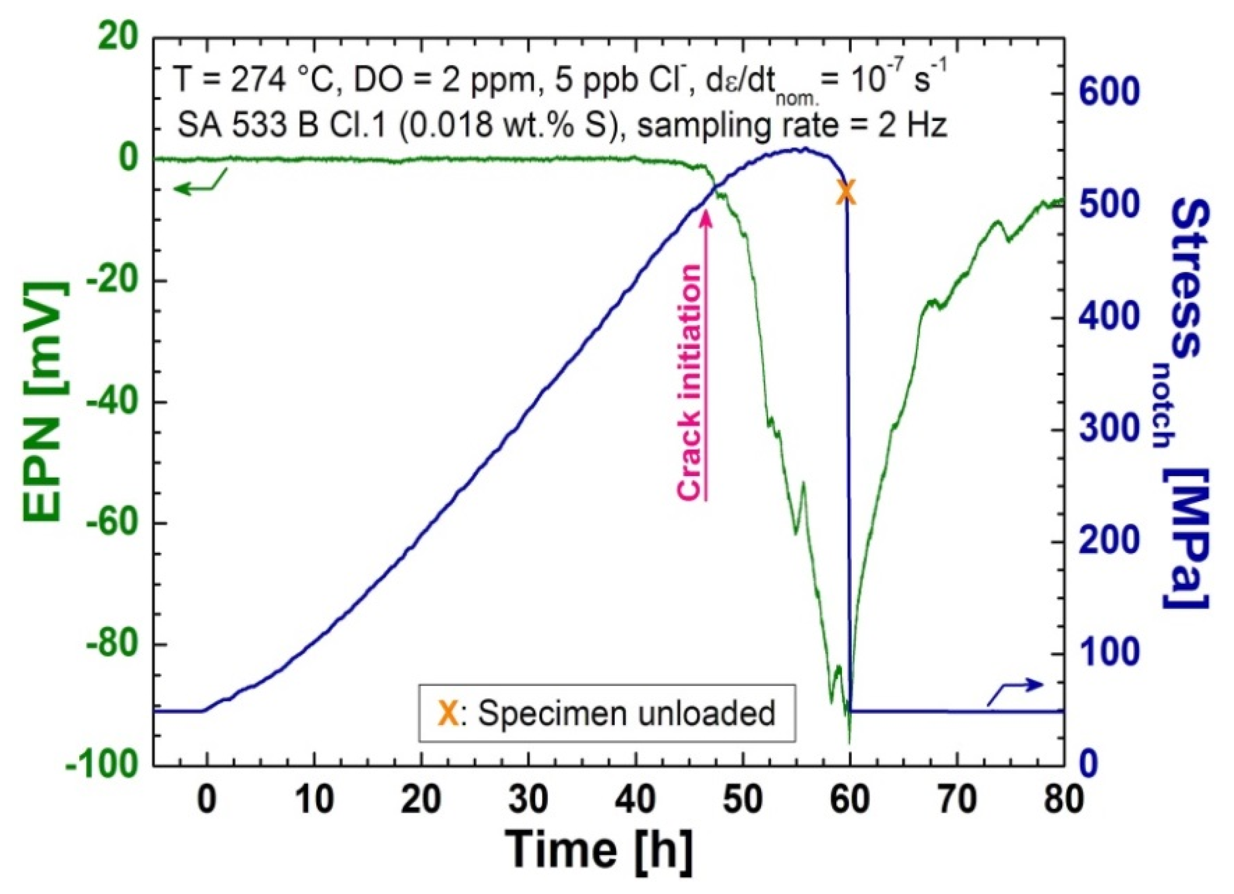
2.2.2. Electrochemical Noise Measurements

The electrochemical potential noise (EPN) was recorded by a commercial electrochemical noise (EN) measurement device (EcmNoise, IPS, Muenster, Germany), developed in cooperation with PSI, with a sampling rate of 2 Hz. The EN measurement device was qualified and characterised by “round-robin” testing (within the European Cooperative Group on Corrosion Monitoring of Nuclear Materials, or ECG-COMON [20,21]) and by dummy cell testing according to a guideline for the assessment of EN measurement devices [22]. The EPN was measured via a Pt-wire (pseudo reference electrode) which was aligned around the V-notch of the specimen (Figure 4). This setup was developed, optimised, and verified during earlier research programmes [23,24].

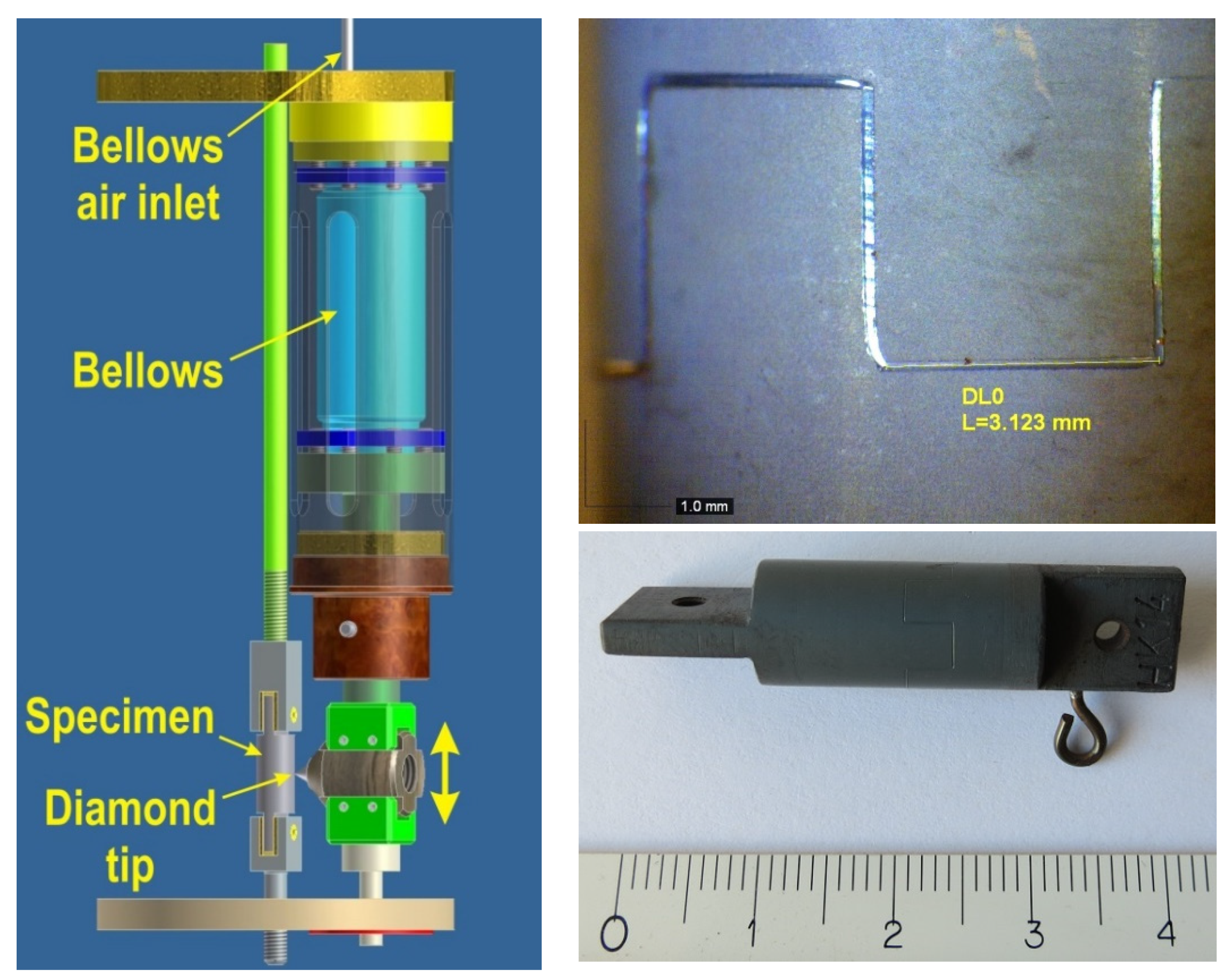
2.2.3. Bellows-Driven Scratching Device

To obtain new insights into the mechanism behind the effect of chloride on crack initiation, the repassivation behaviour of the LAS in a simulated BWR/NWC environment was studied in an autoclave with a bellows-driven scratching device. A pneumatic metal bellow moved a diamond tip across a round LAS specimen (see Figure 5). By up and down movements of the diamond tip and by turning the specimens, up to 16 scratches (each with a length of approximately 3.2 mm) could be implemented on one specimen per experiment. During the test, the current between the specimen and a platinum sheet mounted very close to the specimen surface was recorded with the EN measurement instrument. The specimen, diamond tip, and platinum sheet were electrically insulated from the autoclave and from each other. Several tests were performed in, either, high-purity or 20 ppb chloride-containing high-temperature water.

3. Results and Discussion

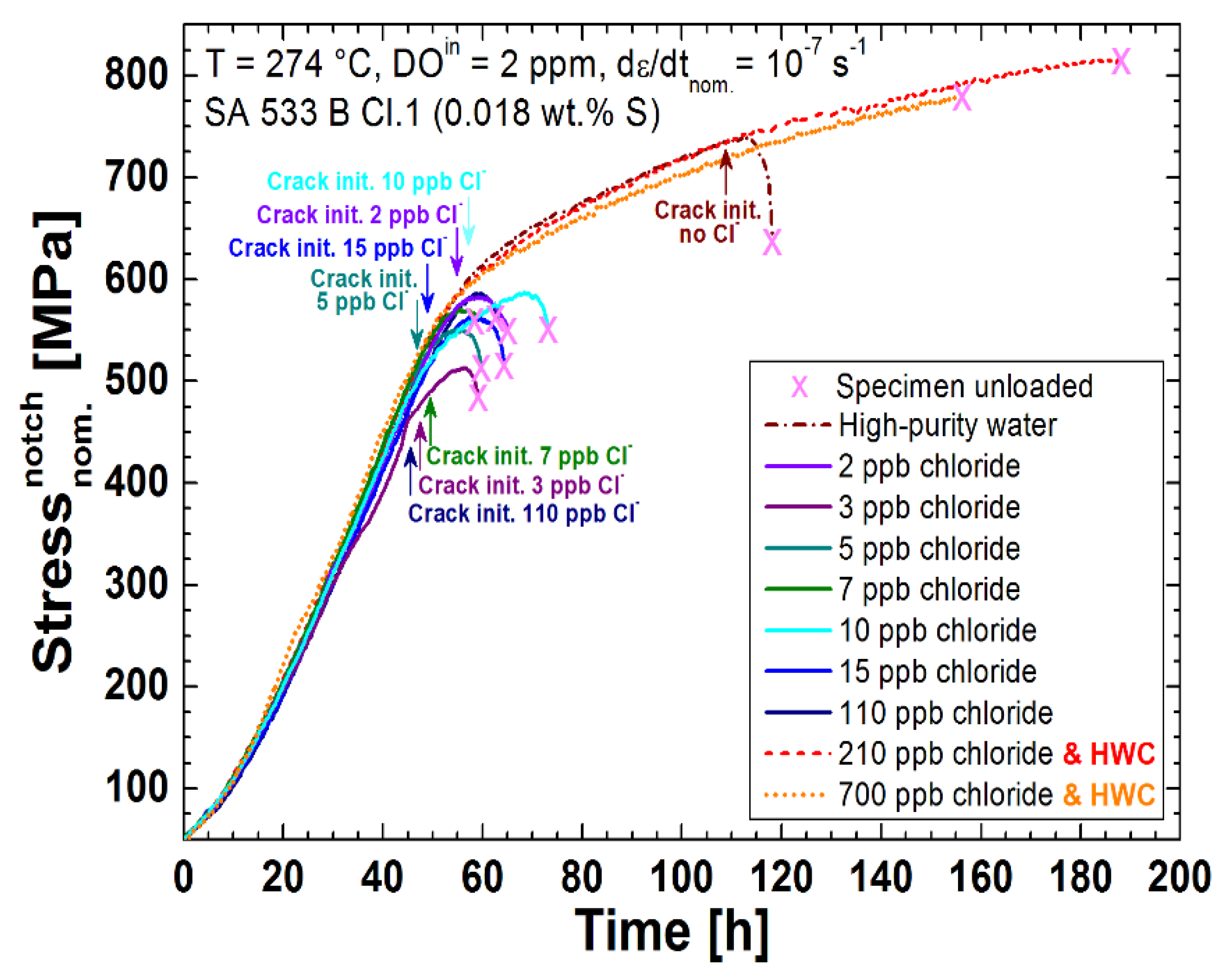
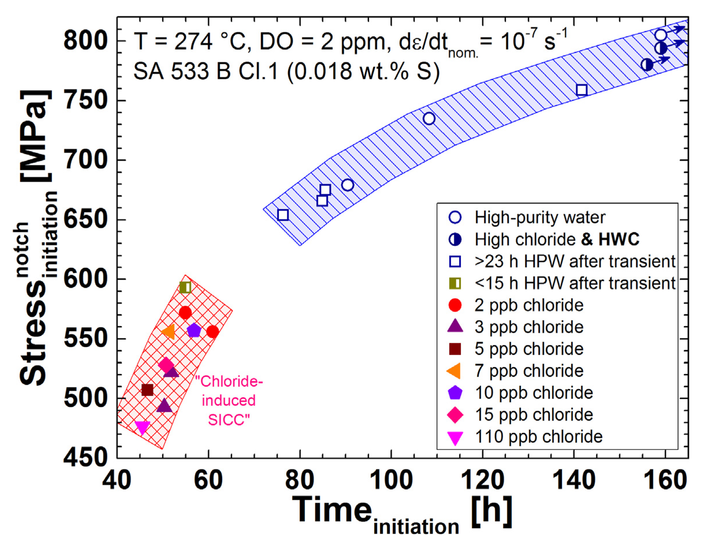
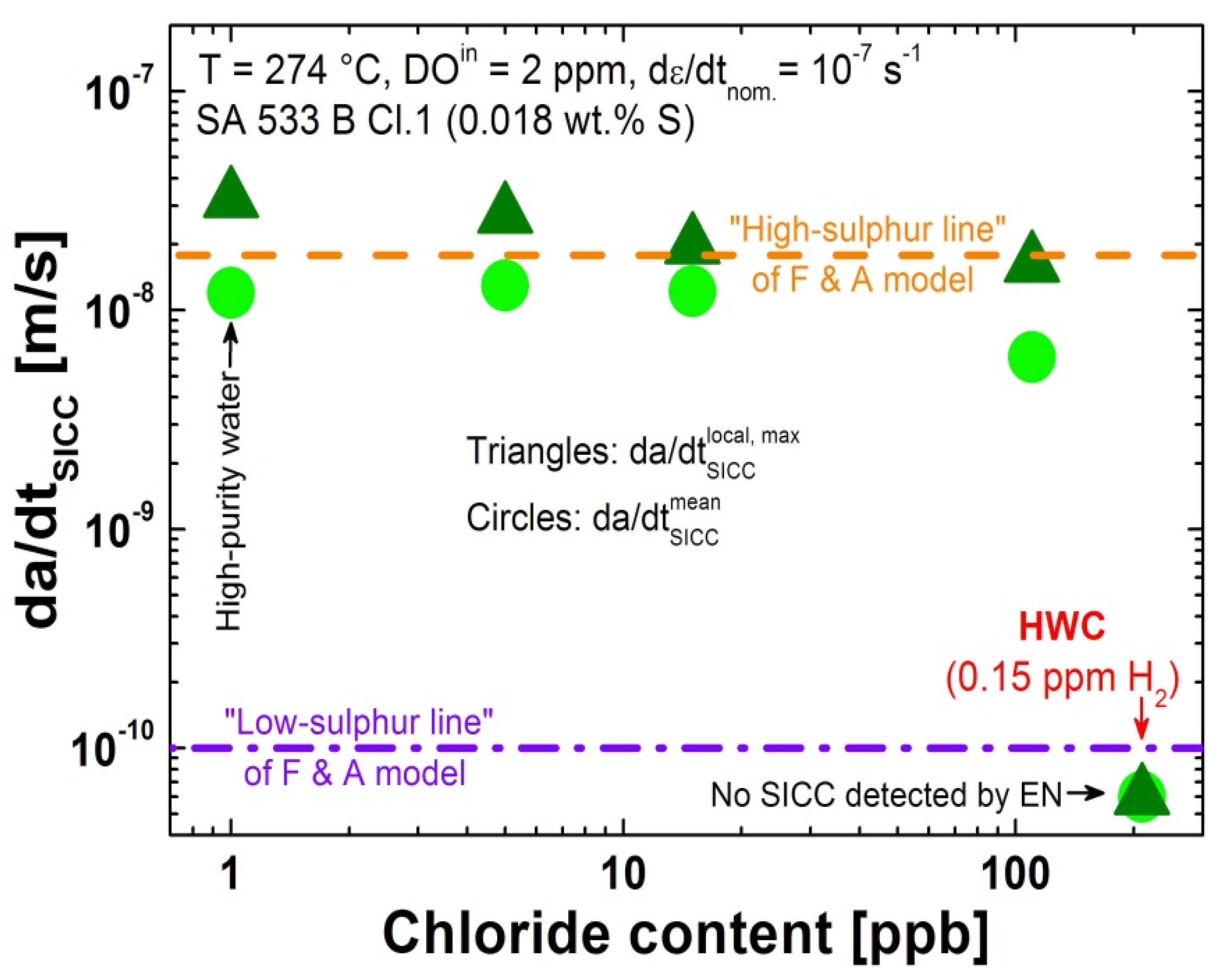
3.1. CERT Tests with Continuous Chloride Addition

A series of 14 CERT tests with continuous chloride addition, or in high-purity water (as reference tests), were performed. In all tests in a BWR/NWC environment, crack initiation could be detected successfully by the EN measurements. Figure 6 shows the typical behaviour of the EPN signal (and stress) during a test where EAC, more precisely SICC, was initiated around the onset of plastic yielding at the notch root. This was shown by a clear drop of the baseline potential signal and by small potential transients in some cases. After the specimen was unloaded to the small pre-load, the EPN signal slowly returned to the original level. The fractographical post-test investigations showed transgranular SICC cracking with features typically observed in EAC tests with LAS in a high-temperature water environment Figure 7. [2,7]. This behaviour of the EPN signal was observed in many tests of previous studies [25] and could be clearly attributed to EAC initiation. The observed cathodic drift of the potential was probably related to oxide film rupture and anodic metal dissolution (sometimes interrupted or delayed by repassivation) during crack initiation at different surface locations, as well as to surface crack growth of previously formed microcracks. The initiation process of EAC, thus, involves local anodic metal dissolution, which is in line with the slip-dissolution mechanism [26]. The superposition of potential signals from the initiation events at different surface locations and the surface crack growth of microcracks under slow straining conditions with increasing plastic strain may result in this quasi-continuous drop in potential. Furthermore, superimposed crevice currents and the resulting potential changes to the differential aeration cell in the crack-mouth region, which vary with the crack-mouth opening, further contribute to these signal changes. Therefore, individual potential transients, as expected, cannot be resolved in every case and, in particular, for large distances between the specimen surface and reference electrode, due to the low throwing power of the current in the low-conductivity electrolyte.
The stress curves and crack initiation times of the most relevant tests are plotted in Figure 8 and all the results are summarised in Table 5 and Figure 9. In the chloride-containing (2 to 110 ppb) BWR/NWC environment, EAC initiation occurred around the onset of plastic yielding and at much smaller nominal strains than in high-purity water. The initiation strains were similar for 2 to 15 ppb of chloride and only slightly higher than for 110 ppb chloride. To double check this behaviour, two further tests in high-purity water were performed, which confirmed the clearly higher initiation strain under these conditions. In the reducing HWC environment with 210 ppb or even 700 ppb of continuous chloride addition, on the other hand, no EAC was detected by EN up to very high strains (the tests were finished after 188 and 156 h, respectively). These results clearly show the tremendous effect of extremely small amounts of chloride on the EAC initiation process in LAS in a highly oxidising BWR/NWC environment. Due to the fact that it is very difficult to perform well-controlled experiments with less than 2 ppb chloride concentration, it is difficult to define a more precise critical chloride threshold value. More tests with ≥700 ppb chloride in hydrogenated high-temperature water at low ECPs are needed to quantify the higher chloride tolerance in BWR/HWC environment.
In contrast, the chloride had very little effect on the subsequent SICC crack growth rates under the slow straining loading conditions (Figure 10), which were all in the range of the “high-sulphur line” growth rates predicted by the Ford and Andresen model [5]. All these results are consistent with previous observations of slow-rising load experiments with pre-cracked compact tension specimens [10].

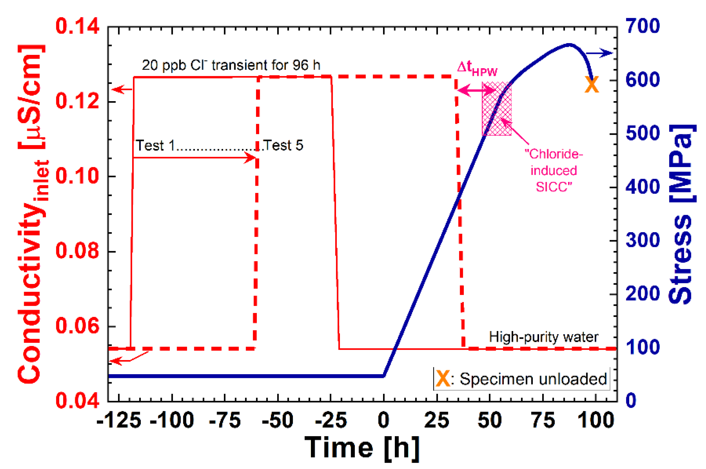
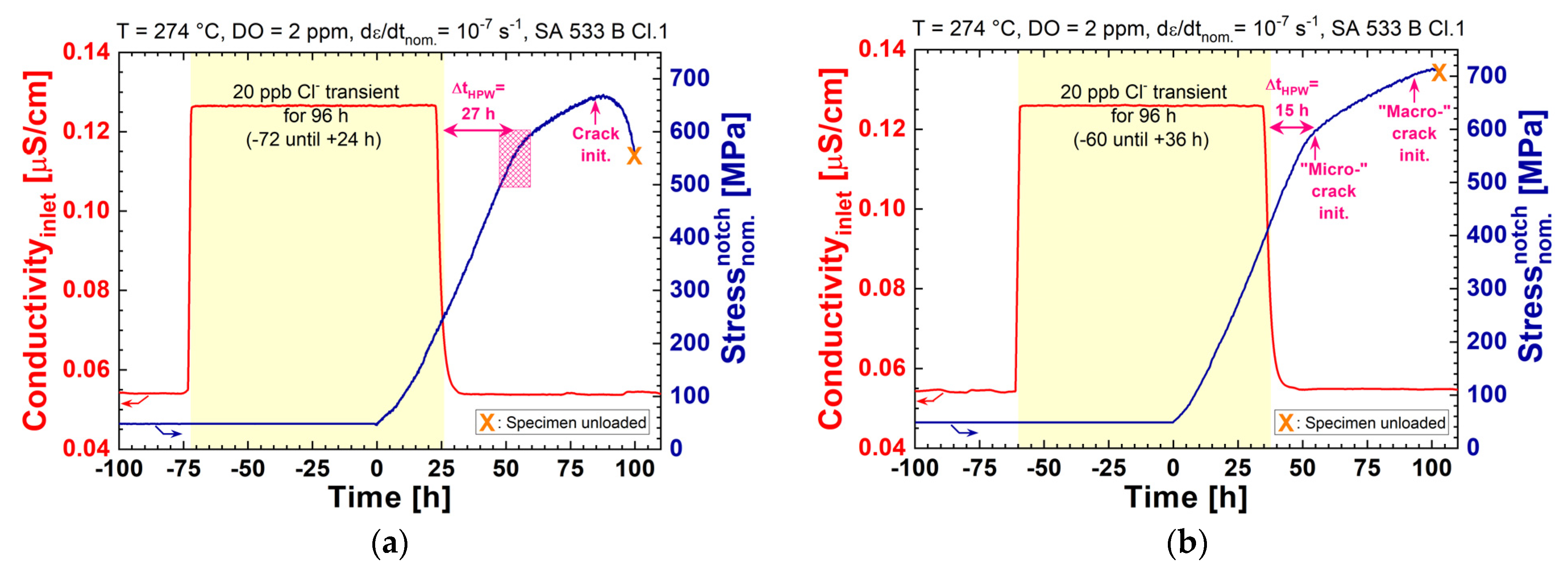
3.2. CERT Tests with Temporary Chloride Transients

The effect of temporary chloride transients on the crack initiation was investigated by five CERT tests. A 96 h-lasting 20 ppb chloride transient was applied either 120, 96, 72, 68, or 60 h before the loading phase started (see Table 4 and Figure 3), which means that the high-temperature water was chloride free 75, 51, 27, 23, or 15 h before reaching the load level where usually chloride-induced SICC was observed during the tests with continuous addition of chloride (see previous section). The specimens in the first four experiments (tests number 1 to 4 in Table 4 and Table 6, ΔtHPW ≥ 23 h) showed no major influence of the temporary chloride transient, and behaved comparable to experiments in high-purity water. An example is shown in Figure 11a. In Figure 9, all crack initiation results are compared with the results of the CERT tests with continuous chloride addition. Only in the last experiment (test number 5 in Table 4 and Table 6), “early” crack initiation was observed 15 h after returning to high-purity water (see Figure 9 and Figure 11). According to these observations, it seems that, for the used LAS, the minimum time needed for a full recovery from a 96 h-long 20 ppb chloride transient is in the range of 16 to 23 h. With more severe chloride transients and existing cracks/flaws, the recovery time can be much longer and, therefore, the memory effects of the chloride cannot be excluded. Even though the material (high sulphur content) and loading parameters (continuous straining of the specimen) were chosen to be rather aggressive and, therefore, conservative, more tests with different LASs and different transients are needed to determine the possible memory effects of the chloride or a more precise minimum recovery time.

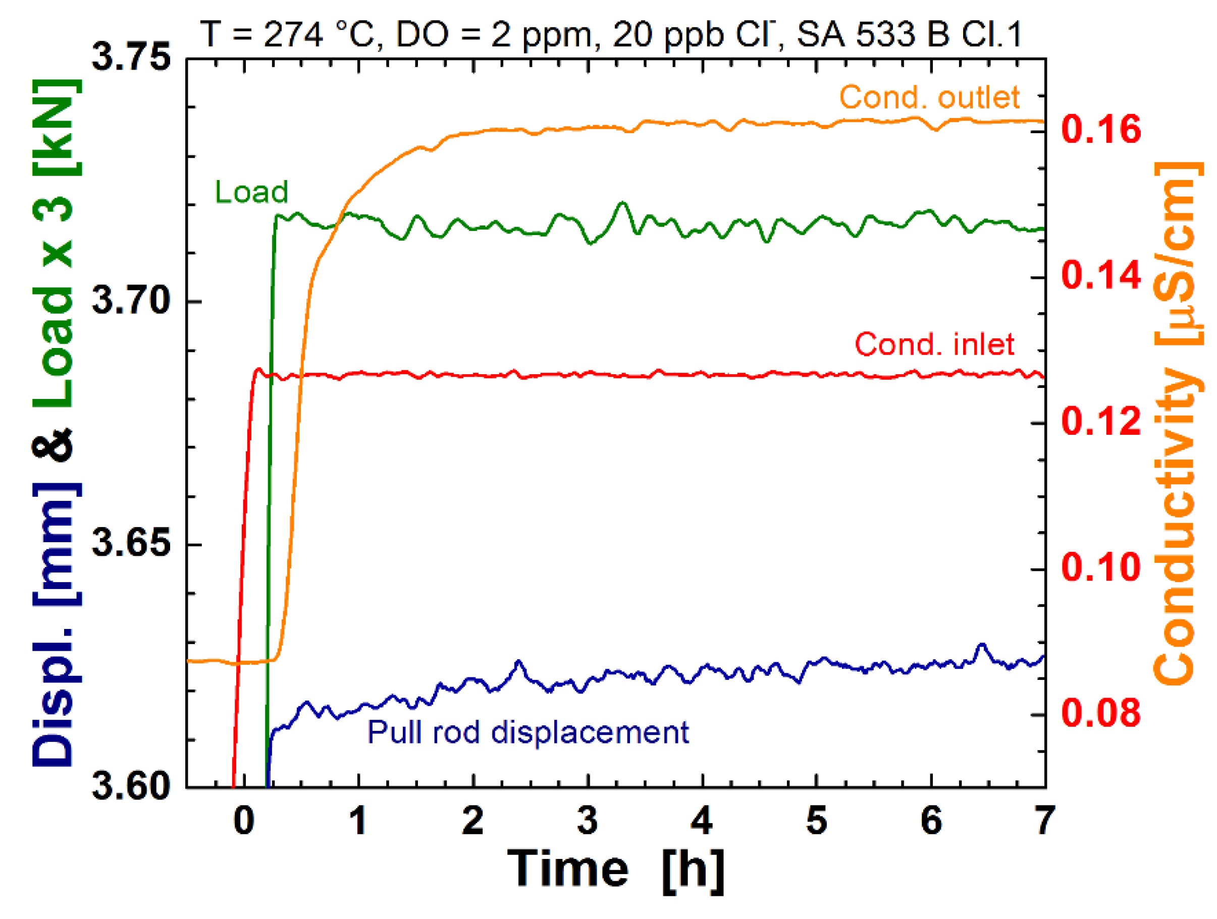
3.3. Constant Load Tests with Continuous Chloride Addition

Finally, the influence of chloride impurities on the crack initiation under constant load was studied by two long-term experiments with the notched round bar tensile specimens. A nominal stress level of 540 MP, at the notch root (130% of YS), was chosen for the tests in order to be in the region where chloride-induced SICC initiation occurred in the CERT tests described before. To avoid crack initiation during the rising load phase, 20 ppb of chloride was added shortly after the final stress level was reached. After almost 1000 h, no cracks were detected by the EN technique and, also, careful fractographical examinations of the specimens, after the test by SEM, did not reveal any cracks. In the second test, the chloride was added slightly earlier when the significant low-temperature creep and, thus, moderate straining of the specimen surface was still present (see Figure 12); also here, no crack initiation occurred during the 10.4 weeks of constant load. Rather severe mechanical transients seem to be necessary to trigger chloride-induced crack initiation from surfaces without pre-existing cracks/flaws.

3.4. Mechanistic Considerations

The reason for the tremendous effect of the very low concentrations of chloride on EAC initiation of LAS in a BWR/NWC environment is still under discussion. Chloride anions might penetrate into the oxide film (in exchange with O2−), which might alter the properties and structure of the protecting oxide film (e.g., increased conductivity and dissolution rate of the oxide layer). A thinner and more brittle oxide film could lead to more frequent film rupture events at a lower rupture strain and, therefore, to more metal dissolution. Furthermore, repassivation of the bare metal regions could be delayed by the chloride. TOF-SIMS measurements by Herbst et al. [11,27] confirmed that chloride is absorbed in the oxide film of LAS specimens exposed to chloride-containing high-temperature water. He also observed a thinning of the protective oxide layer, as well as an increased appearance of pits on the LAS surfaces if chloride was present in the high-temperature water. The study of Saario et al. [28,29,30] revealed similar observations. The fact that active mechanical straining of the specimen, at least in the case of low chloride contents, is necessary for the appearance of chloride-induced EAC indicates that the mechanical rupture of the protective oxide film is a pre-requisite for the chloride anions to act as an accelerating factor for EAC. After this rupture of the oxide film, a delayed repassivation caused by chloride anions might be a further influencing factor.
To obtain at least some insights into the impact of chloride on the repassivation behaviour, a series of scratching tests with current measurements under simulated BWR/NWC conditions with and without chloride addition were performed. In Figure 13, examples of current transients, caused by removing the oxide film along a scratch, are shown for a chloride-free and 20 ppb chloride-containing oxygenated high-temperature water environment. In the case of chloride, the current needed more time to reach the baseline current and, therefore, to fully repassivate. Despite a rather large scatter in the repassivation times, a clear trend was revealed after evaluating 33 scratches, with an average repassivation period of 127 min in the case of the chloride-contaminated water vs. 99 min in high-purity water. Therefore, it seems that repassivation is slightly delayed by the chloride anions.
Considering the limited information available from PSI’s experience and literature data on the mechanism behind chloride-induced EAC and based on the film rupture/anodic dissolution model of Ford and Andresen [2,4,5], it is believed that a combination of all the phenomena described above may contribute to the chloride-enhanced crack initiation process. The thinning of the protective oxide film, together with a decreased rupture strain, might increase the number of rupture events caused by mechanical straining and exposes more areas of bare metal to the water. Anodic metal dissolution occurs and may be active for longer periods because the repassivation is delayed. Together with a higher number of pits present on the surface of the steel that may act as preferred crack initiation sites, this may lead to more cracks. These cracks then tend to grow due to the enrichment of chloride in the crack enclave (caused by the chloride ion migration, driven by the potential gradient between the oxygenated bulk environment and oxygen-depleted crack-tip electrolyte; results of crack-tip micro-sampling indicated a 20 times higher chloride concentration compared with the bulk environment [27]. The calculations of Bojinov et al. [28] resulted in a chloride enrichment factor of 30. This potential gradient, and accumulation of chloride ions in the crack crevice, is absent in the reducing environment which may explain the higher chloride tolerance in the HWC environment. This also means that for weakening a thick and stable oxide film which has been developed in chloride-free high-purity water, very high chloride concentrations for longer periods of time are needed. The negative impact of chloride is stronger in the early stages of oxide film formation, e.g., after a film rupture event [28,29,30]. Local damage of a stable chloride-free oxide layer is rather unlikely. As we have shown here and in earlier investigations [8,9,10], either a growing crack or a mechanical transient with plastic deformation of the water-wetted steel surface is needed to reveal the effect of the chloride on EAC initiation or crack growth.
More mechanistic investigations are needed to provide a more conclusive picture of the whole mechanism behind the tremendous effect of extremely small chloride contaminations on the EAC initiation and growth behaviour of LAS in oxidising a BWR/NWC environment.

4. Summary and Conclusions

To study the effect of chloride on the EAC initiation behaviour of LAS under BWR conditions, a series of CERT tests in high-temperature water with notched round bar tensile specimens and EN measurements were performed. During the tests with continuous chloride addition (to the simulated highly oxidising BWR/NWC water) down to concentration levels of 2 ppb, EAC initiation was detected at much lower strains than in tests with high-purity water. Under reducing BWR/HWC conditions, a chloride content of up to 700 ppb was not sufficient to initiate EAC up to the investigated strain. No major effect of the chloride on the subsequent SICC crack growth rates was observed, which is consistent with earlier investigations with pre-cracked compact tension specimens. CERT tests with moderate short-term chloride transients revealed that, only one day after returning to the high-purity water, the steel fully recovered from the chloride excursion. Load-controlled tests under pure constant load showed no increased susceptibility to EAC in the presence of 20 ppb of chloride, if mechanical transients are avoided. Scratching tests indicated that the repassivation of the LAS surface seems to be slightly delayed in the presence of chloride. Finally, for BWR/NWC plant operation it may be concluded that, in the reactor water, even low levels of chloride impurities should be avoided, especially in the presence of slow but severe load transients.

Author Contributions

Conceptualization, S.R. and H.-P.S.; methodology, S.R. and H.-P.S.; validation, S.R. and H.-P.S.; investigation, S.R.; resources, S.R.; data curation, S.R.; writing—original draft preparation, S.R.; writing—review and editing, H.-P.S.; project administration, H.-P.S.; funding acquisition, H.-P.S. All authors have read and agreed to the published version of the manuscript.

Funding

This research was funded by the Swiss Federal Nuclear Safety Inspectorate (ENSI).

Institutional Review Board Statement

Not applicable.

Informed Consent Statement

Not applicable.

Data Availability Statement

The data presented in this study are available on reasonable request from the corresponding author.

Acknowledgments

The financial support of the research programme by the Swiss Federal Nuclear Safety Inspectorate (ENSI) is gratefully acknowledged. Thanks are also expressed to B. Baumgartner, L. Nue and R. Schwenold (all PSI) for their experimental contribution to this work and to K. Reichlin (PSI) for the finite element calculations.

Conflicts of Interest

The authors declare no conflict of interest. The funders had no role in the design of the study; in the collection, analyses, or interpretation of data; in the writing of the manuscript; or in the decision to publish the results.

References

  1. Seifert, H.P.; Ritter, S. Stress Corrosion Cracking of Low-Alloy Reactor Pressure Vessel Steels under Boiling Water Reactor Conditions. J. Nucl. Mater. 2008, 372, 114–131. [Google Scholar] [CrossRef]
  2. Seifert, H.P.; Ritter, S. Research and Service Experience with Environmentally-Assisted Cracking of Carbon & Low-Alloy Steels in High-Temperature Water; 2005:60; SKI: Stockholm, Sweden, 2005. [Google Scholar]
  3. Seifert, H.P.; Ritter, S.; Hickling, J. Research and Service Experience with Environmentally-Assisted Cracking of Low-Alloy Steel Pressure-Boundary Components under LWR Conditions. PowerPlant Chem. 2004, 6, 111–123. [Google Scholar]
  4. Ford, F.P. Environmentally Assisted Cracking of Low-Alloy Steels; EPRI NP-7473-L; Electric Power Research Institute: Palo Alto, CA, USA, 1992. [Google Scholar]
  5. Ford, F.P. Quantitative prediction of environmentally assisted cracking. Corrosion 1996, 52, 375–395. [Google Scholar] [CrossRef] [Green Version]
  6. Scott, P.; Tice, D. Stress corrosion in low alloy steels. Nucl. Eng. Des. 1990, 119, 399–413. [Google Scholar] [CrossRef]
  7. Seifert, H.P.; Ritter, S. 5—Environmentally-assisted cracking of carbon and low-alloy steels in light water reactors. In Nuclear Corrosion: Research, Progress and Challenges, 1st ed.; Ritter, S., Ed.; EFC Publications No. 69; Woodhead Publishing: Cambridge, UK, 2020; pp. 119–211. [Google Scholar]
  8. Seifert, H.P.; Ritter, S.; Leber, H.J.; Roychowdhury, S. Stress corrosion cracking behavior in the transition region of alloy 182/low-alloy reactor pressure vessel steel dissimilar metal weld joints in light water reactor environments. Corrosion 2015, 71, 433–454. [Google Scholar] [CrossRef]
  9. Seifert, H.P.; Ritter, S. The influence of ppb levels of chloride impurities on the stress corrosion crack growth behaviour of low-alloy steels under simulated boiling water reactor conditions. Corros. Sci. 2016, 108, 134–147. [Google Scholar] [CrossRef]
  10. Seifert, H.P.; Ritter, S. The influence of ppb levels of chloride impurities on the stain-induced corrosion cracking and corrosion fatigue crack growth behavior of low-alloy steels under simulated boling water reactor conditions. Corros. Sci. 2016, 108, 148–159. [Google Scholar] [CrossRef]
  11. Herbst, M.; Roth, A. Investigations on the effect of chloride on the general corrosion behavior of low-alloy steels in oxygenated high-temperature water. Mater. Corros. 2013, 64, 691–699. [Google Scholar] [CrossRef]
  12. Herbst, M.; Roth, A.; Widera, M. Summary of the Results of a German Research Project on Chloride Effects on the General Corrosion and Stress Corrosion Cracking Behavior of LAS under BWR Conditions. In Proceedings of the 17th International Conference on Environmental Degradation of Materials in Nuclear Systems—Water Reactors, Ottawa, ON, Canada, 9–13 August 2015. [Google Scholar]
  13. Lou, X.; Andresen, P.L.; Lian, T.; Pathania, R. Effect of ppb Levels of Chloride on the Stress Corrosion Cracking of Pressure Vessel Steel. In Proceedings of the 17th International Conference on Environmental Degradation of Materials in Nuclear Systems—Water Reactors, Ottawa, ON, Canada, 9–13 August 2015. [Google Scholar]
  14. Lou, X.; Pathania, R. Effect of chloride transients on crack growth rates in low alloy steels in BWR environments. In Proceedings of the 18th International Conference on Environmental Degradation of Materials in Nuclear Systems—Water Reactors, Portland, OR, USA, 13–17 August 2017; pp. 433–445. [Google Scholar]
  15. Lou, X.; Pathania, R.; Andresen, P.L. Effects of chloride transients on stress corrosion crack in pressure vessel low alloy steels in high temperature water. Corros. Sci. 2017, 126, 305–316. [Google Scholar] [CrossRef]
  16. Lou, X.; Andresen, P.L.; Yang, J.; Pathania, R.; Lian, T.; Carter, R.G. Mechanical and metallurgical considerations on the effects of ppb-level chloride on stress corrosion cracking of low alloy steels in high-temperature water. Corros. Sci. 2021, 179, 109136. [Google Scholar] [CrossRef]
  17. Odell, D.; McGehee, A. Interim Guidance for BWR Water Chemistry Guidelines (BWRVIP Letter 2016-123); EPRI: Palo Alto, CA, USA, 2016; p. 64. [Google Scholar]
  18. Seifert, H.P.; Ritter, S.; Spätig, P.; Bai, J.; Roychowdhury, S. Safe Long-Term Operation in the Context of Environmental Effects on Fracture, Fatigue and Environmentally-Assisted Cracking—Final Report of the SAFE-I Project; No. 15-03; Paul Scherrer Institut: Villigen, Switzerland, 2015; p. 215. [Google Scholar]
  19. Cheng, B.; Gilman, J.; Nelson, L.; Pathania, R.; Wood, C. BWR Water Chemistry Guidelines—1996 Revision; EPRI TR-103515-R1; Electric Power Research Institute: Palo Alto, CA, USA, 1996. [Google Scholar]
  20. European Cooperative Group on Corrosion Monitoring of Nuclear Materials—ECG-COMON. Available online: http://www.ecg-comon.org (accessed on 10 January 2022).
  21. Bosch, R.-W.; Cottis, R.A.; Csecs, K.; Dorsch, T.; Dunbar, L.; Heyn, A.; Huet, F.; Hyökyvirta, O.; Kerner, Z.; Kobzova, A.; et al. Reliability of electrochemical noise measurements: Results of round-robin testing on electrochemical noise. Electrochim. Acta 2014, 120, 379–389. [Google Scholar] [CrossRef] [Green Version]
  22. Ritter, S.; Huet, F.; Cottis, R.A. Guideline for an assessment of electrochemical noise measurement devices. Mater. Corros. 2012, 63, 297–302. [Google Scholar] [CrossRef]
  23. Ritter, S.; Seifert, H.P. Detection of SCC initiation in austenitic stainless steel by electrochemical noise measurements. Mater. Corros. 2013, 64, 683–690. [Google Scholar] [CrossRef]
  24. Ritter, S.; Seifert, H.P. Influence of reference electrode distance and hydrogen content on the electrochemical potential noise during SCC in high-purity, high-temperature water. Corros. Eng. Sci. Technol. 2013, 48, 199–206. [Google Scholar] [CrossRef]
  25. Ritter, S.; Seifert, H.P. Detection of stress corrosion cracking in a simulated BWR environment by combined electrochemical potential noise and direct current potential drop measurements. In Corrosion Monitoring in Nuclear Systems: Research and Applications; Ritter, S., Molander, A., Eds.; EFC Publications No. 56; Maney Publishing: London, UK, 2010; pp. 46–62. [Google Scholar]
  26. Andresen, P.L.; Ford, F.P. Modeling and Life prediction of Stress Corrosion Cracking in Sensitized Stainless Steel in High Temperature Water. In Predictive Capabilities in Environmentally Assisted Cracking; Rugta, R., Ed.; ASME: New York, NY, USA, 1985; pp. 17–39. [Google Scholar]
  27. Herbst, M. Effect of Chloride on Environemtally Assisted Cracking of Low Alloy Steels in Oxygenated High-Temperature Water; Liverpool John Moores University: Liverpool, UK, 2013. [Google Scholar]
  28. Bojinov, M.; Nowak, E.; Stanislowski, M.; Saario, T. Effect of chloride transients on the corrosion behavior of low-alloy steels in cladding flaws of reactor pressure vessels under oxygenated high-temperature water conditions. Atw-Int. J. Nucl. Power 2014, 60, 221–227. [Google Scholar]
  29. Sipilä, K.; Bojinov, M.; Mayinger, W.; Saario, T.; Stanislowski, M. Effect of chloride and sulfate additions on corrosion of low alloy steel in high-temperature water. Electrochim. Acta 2015, 173, 757–770. [Google Scholar] [CrossRef]
  30. Sipilä, K.; Bojinov, M.; Mayinger, W.; Saario, T.; Selektor, M. Corrosion mechanism of low-alloyed steel in high-temperature water: Effect of additives and time of exposure. J. Electrochem. Soc. 2016, 163, C530–C538. [Google Scholar] [CrossRef]
Figure 1. Schematic of the round bar tensile specimen with V-shaped notch (dimensions in mm).
Cmd 03 00010 g001
Figure 2. Schematic of the high-temperature water loop with autoclave and electro-mechanical tensile machine.
Cmd 03 00010 g002
Figure 3. Schematic of the testing procedure of the five CERT tests with 20 ppb chloride transients (SICC = strain-induced corrosion cracking).
Cmd 03 00010 g003
Figure 4. Simplified schematic (left) and photograph (right) of the setup for the EPN measurements, during CERT, and constant load tests with notched round bar tensile specimens.
Cmd 03 00010 g004
Figure 5. Schematic of the bellows-driven scratching device (left), photograph (lower right), and detail (upper right) of a specimen after a scratching test.
Cmd 03 00010 g005
Figure 6. Typical course of the EPN signal and stress (at a smaller cross-sectional area in the notch) during a CERT test in high-temperature water containing 5 ppb of chloride; crack initiation was detected by the drop of the potential signal.
Cmd 03 00010 g006
Figure 7. SEM secondary electron micrographs of crack flanks (specimen opened after the experiment) of the specimen from a test with addition of 5 ppb chloride (left) and with addition of 3 ppb chloride (right). Typical transgranular SICC with “fan-shaped” features and crack branching can be observed (surface covered with oxide film).
Cmd 03 00010 g007
Figure 8. Effect of chloride on the crack initiation under simulated BWR conditions; EAC initiation was delayed in high-purity water or in reducing HWC environment.
Cmd 03 00010 g008
Figure 9. Summary of all CERT test results (points with arrows indicate that no clear signs of EAC initiation could be detected before the test was finished).
Cmd 03 00010 g009
Figure 10. No effect of chloride on the subsequent SICC crack growth rate under simulated BWR conditions; the crack growth rates are in the range of the “high-sulphur line” of the Ford and Andresen crack growth model [5].
Cmd 03 00010 g010
Figure 11. Effect of short-term chloride transients on the crack initiation under simulated BWR/NWC conditions. Crack initiation was delayed in test number 3 (a); during test number 5, first signs of crack initiation (=“micro-” crack initiation) were detected in the EPN signal 15 h after returning to high-purity water (b).
Cmd 03 00010 g011
Figure 12. Detail of the initial loading of the specimen during the second constant load test showing the course of the load, pull rod displacement, and inlet/outlet water conductivity.
Cmd 03 00010 g012
Figure 13. Examples of current (density) transients measured during scratching of a LAS specimen in high-purity (a) and 20 ppb chloride-containing (b) oxygenated high-temperature water.
Cmd 03 00010 g013
Table 1. EPRI water chemistry guideline recommendations for the reactor water during stationary BWR power operation for normal (NWC) and hydrogen water chemistry (HWC) conditions (NMCA = noble metal chemical addition) [17].
ParameterBWR NWCBWR HWC or NMCAAllowed Time for Reduction of Parameter below AL
Action level 1Chloride≥3 ppb>5 ppb96 h
Sulphate>5 ppb>5 ppb96 h
Action level 2Sulphate & chloride>20 ppb>50 ppb24 h
Action level 3Sulphate & chloride>100 ppb>200 ppb0 h
Good practiceSulphate<2 ppb<2 ppb--
Good practiceChloride<1 ppb<1 ppb--
Table 2. Chemical composition of the investigated LAS in wt.%.
CSiMnPSCrMoNiVAlCu
SA 533 B Cl.10.250.241.420.0060.0180.120.540.620.0070.030.15
Table 3. Mechanical properties of the investigated LAS (YS = yield strength, UTS = ultimate tensile strength, A = elongation at fracture, and Z = reduction of area).
YS (25 °C)
[MPa]
UTS (25 °C)
[MPa]
A (25 °C)
[%]
Z (25 °C)
[%]
YS (288 °C)
[MPa]
SA 533 B Cl.145660523.459.9412
Table 4. Summary of the 20 ppb chloride transient tests; ΔtHPW = time between end of chloride transient (inlet conductivity < 0.066 μS/cm) and stress/strain regime where strain-induced corrosion crack initiation was usually observed in tests with continuous chloride addition, see Figure 3.
Test Numbertstart [h]tend [h]Δt [h]ΔtHPW [h]
1−120−249675
2−9609651
3−72249627
4−68289623
5−60369615
Table 5. Summary of the CERT test results with continuous chloride addition (σinitiation = nominal stress at time of crack initiation, Δtinitiation = time from start of loading until crack initiation, ΔtCERT = time from start of loading until unloading, Δamean/max = average/maximum crack depth, and N.E. = not evaluated).
Test NumberEnvironmentChloride Content [ppb]σinitiation [MPa]Δtinitiation [h]ΔtCERT [h]Δamean [mm]Δamax [mm]da/dtmean [m/s]da/dtmax [m/s]
6NWC<0.67351081180.4261.1401.2 × 10−83.2 × 10⁻⁸
7NWC<0.6>822>189189N.E.N.E.N.E.N.E.
8NWC<0.667991107N.E.N.E.N.E.N.E.
9NWC25566175N.E.N.E.N.E.N.E.
10NWC25725565N.E.N.E.N.E.N.E.
11NWC35225264N.E.N.E.N.E.N.E.
12NWC34935059N.E.N.E.N.E.N.E.
13NWC55074760.00.6271.3141.3 × 10−82.7 × 10⁻⁸
14NWC75565159N.E.N.E.N.E.N.E.
15NWC105575774N.E.N.E.N.E.N.E.
16NWC1551749650.7051.1371.2 × 10−82.0 × 10⁻⁸
17NWC11047746620.3690.9806.1 × 10−91.6 × 10⁻⁸
18HWC210>817>188188N.E.N.E.N.E.N.E.
19HWC700>780>156156N.E.N.E.N.E.N.E.
Table 6. Summary of the CERT test results with temporary chloride addition/transients (σinitiation = nominal stress at time of crack initiation, Δtinitiation = time from start of loading until crack initiation).
Test NumberEnvironmentChloride Content (for 96 h Period) [ppb]σinitiation [MPa]Δtinitiation [h]
1NWC2065476
2NWC2067586
3NWC2066685
4NWC20759142
5NWC2059355
Publisher’s Note: MDPI stays neutral with regard to jurisdictional claims in published maps and institutional affiliations.

