
Comparative Appraisal of Three Low-Cost GPS Speed Sensors with Different Data Update Frequencies


1
Department of Plant Production and Technologies, Faculty of Agricultural Sciences and Technologies, Nigde Omer Halisdemir University, 51240 Nigde, Turkey
2
Department of Biosystems Engineering, Faculty of Agriculture, Hatay Mustafa Kemal University, 31040 Antakya, Turkey
*
Author to whom correspondence should be addressed.
AgriEngineering 2021, 3(2), 423-437; https://0-doi-org.brum.beds.ac.uk/10.3390/agriengineering3020028
Submission received: 2 May 2021
/
Revised: 9 June 2021
/
Accepted: 9 June 2021
/
Published: 16 June 2021
(This article belongs to the Special Issue Electronics of Agricultural Mechanization)
Abstract
:Low-cost GPS (Global Positioning System) speed sensors have been available to quantify vehicle speed on different platforms including agricultural tractors in precision agriculture applications such as yield monitoring, variable rate fertilizer and pesticide applications. One of the advances in low-cost GPS receivers is the higher data update frequencies. However, we found no studies on the accuracy of low-cost GPS speed sensors with different update frequencies, especially under variable speed conditions. Thus, this work investigated the effect of the update frequency on the accuracy of low-cost GPS speed sensors under both constant and varying speed conditions. Three GPS speed sensors with update frequencies of 1 Hz, 5 Hz and 7 Hz (GPS1Hz, GPS5Hz and GPS7Hz) were simultaneously tested under the same conditions. A total of 144 tests were conducted on three different days and at three different times of each day with four speed levels and four repetitions. The percent errors were found to be up to 2.3%, 1.8% and 1.4% at constant speeds; up to −47%, −16% and −12% at the increasing speeds and 24%, 6% and 5% at the decreasing speeds, depending on the acceleration and deceleration levels, for GPS1Hz, GPS5Hz and GPS7Hz, respectively. The differences among the error values of the GPS speed sensors were found to be statistically significant (p < 0.05). The GPS speed sensors with higher update frequencies (5 and 7 Hz) provided higher accuracy compared to the one with lower frequency (1 Hz), particularly in the case of higher acceleration conditions. In sum, low-cost GPS speed sensors with higher update frequencies should be used for better accuracy, especially in variable speed conditions.
1. Introduction
Speed can be defined as how fast an object is moving, while velocity combines the speed and direction in which an entity is moving relative to true north [1]. The quantification of velocity is necessary on various platforms, including road vehicles, off-road vehicles, trains, bikes, humans, ships, aircrafts, etc. The goal of measuring speed may vary based on the application, including the safer operation of vehicles; calculation of power as a product of speed and force; evaluation of driver travel routes based on fuel efficiency and travel time; fuel level tracking to prevent fuel theft; walking speed of diseased persons, mainly those with cardiovascular diseases; speed of humans in social, touristic and economic activities; performance of car racers, horse racers and cyclers; precision farming applications and real-time traffic management [2].
In precision agriculture, ground speed data is essential to calculate, monitor and map crop yield in yield monitoring systems [3,4,5]. It is also required to adjust the rate of agricultural inputs including seeds, fertilizers and pesticides in variable rate applications [1,6,7]. In addition, it is utilized in tractor auto steering systems [1], wheel slip and traction (draft) efficiency evaluation and the consumption of fuel and energy of tractors and self-propelled farm machinery [8,9,10]. Additional use of the speed data is in the calculation of field work capacity (ha h−1), which is the amount of area (hectares) processed in a unit of time (hour) by farm machinery.
Scientists have invented and evaluated various velocity measurement methods, including magnetic shaft encoders, optical shaft encoders, RADAR sensors, ultrasonic sensors, LASER/LIDAR sensors, image processing and GNSS/GPS receivers [2,4,6,7,8,11,12].
In recent years, GNSS (Global Navigation Satellite System) and GPS (Global Positioning System) receivers are increasingly used in velocity determination, along with positioning, navigation and timing (PNT). GNSS-based velocity measurement has some advantages, such as having no moving parts, being suitable for measuring human and animal speed and not affected by tire slippage, dust, ground ruggedness and tall vegetation, while it has some disadvantages, such as having low accuracy in increasing and decreasing speed conditions, low signal quality or acquisition under enclosed areas such as tunnels, overpasses, forests, deep valleys, urban areas, etc. [2]. GNSS and GPS units measure speed based on the following three methods: travelled distance divided by time, Doppler shift and Time-differenced carrier phase (TDCP) [2]. The first method is inaccurate (in the order of m s−1), while the second method (Doppler shift) has better accuracy (cm s−1) and the third one can offer the best accuracy (mm s−1) [2,13,14].
With the advances in technology, new and improved GNSS or GPS receivers, data loggers, trackers and speed sensors are available with a smaller size, lower cost and multi-frequency, receive signals from more than one GNSS constellation and have higher data update frequencies. One of the crucial advances is the higher data update frequencies, up to 20 Hz. In recent years, stand-alone, low-cost GPS speed sensors with a cost of several hundred US dollars have been available. These sensors consist of an antenna, a GPS module, a microprocessor, an optional display and a connector cable (Figure 1).
GPS speed sensors usually send the speed data in pulse signals and are usually used for the replacement of radar speed sensors in agriculture [7]. However, manufacturers do not provide enough information on the speed accuracy of their products, especially under different working conditions including variable speeds [2,15,16]. A limited number of studies have dealt with the speed measurement accuracy of hand-held, high cost and high-performance GPS or GNSS units. However, the cost of equipment is a crucial factor that affects the level of the adoption of a technological system [17,18]. We found no studies on the accuracy of low-cost GPS speed sensors with different update frequencies. Hence, the aim of this research was to study the influence of data update frequencies on the accuracy of three low-cost GPS speed sensors under constant and varying speed conditions simultaneously in same test conditions.
2. Materials and Methods
2.1. GPS Speed Sensors
Three low-cost GPS speed sensors with data update frequencies of 1 Hz, 5 Hz and 7 Hz (GPS1Hz, GPS5Hz, GPS7Hz) were tested in the study. Some technical specifications of these sensors and their images are shown in Table 1 and Figure 2, respectively. All GPS speed sensors were SBAS (WAAS/EGNOS)-enabled (SBAS, Satellite-based augmentation systems; WAAS, Wide area augmentation system; EGNOS, European geostationary navigation overlay service) and required a supply voltage of 9—18 VDC.
2.2. Data Acquisition (DAQ) System
The reference speed measurement system consisted of an optical rotary shaft encoder that is mounted on an auxiliary wheel of an agricultural tractor (Figure 3). Some technical features of the shaft encoder are also given in Table 1. A medium-power four-wheel agricultural tractor (MF 250G, Massey Ferguson, Duluth, GA, USA) was used in the study, which had four gears and two speed levels (slow and fast) (Figure 3). The antennas of the GPS speed sensors were positioned about 0.60 m apart from each other on the top of the tractor’s shade cover. The signals obtained from the optical shaft encoder and the GPS speed sensors were acquired using a laptop computer with a data acquisition card (DAQ) (Table 1). Some technical specifications of the DAQ card are also presented in Table 1. A picture of the data collection system is given in Figure 2. A laptop computer was used to collect and save the data during the experiments.
2.3. Computer Program
A computer program was written in the Arduino IDE (Version: 1.6.9; Somerville, MA, USA) to read, process and display four speed data (from the three GPS speed sensors and the optical shaft encoder) through the DAQ card [19]. The GPS speed sensors and the optical shaft rotary encoder produced square pulse signals (frequency) depending on the speed. The frequency values were converted into speed values. The time-stamped four speed values were displayed on the computer screen. After each speed test was completed, the data were copied from the data screen and saved in a text file for further data processing.
2.4. Calibration of the Reference Speed Measurement System
The reference speed measurement system was calibrated for various speed levels for the four different speed gears. In the calibration, data were taken four times in each speed range (n = 4 × 4 = 16). For this purpose, the stopwatch method (speed = distance/time) was used to determine the actual speed. The tractor was driven at a constant speed over a distance of 30 m and the time elapsed was measured with a stopwatch. The average speed value was calculated by dividing the distance by the time. Regression and calibration equations were calculated using MS Excel 2013 software (Microsoft, Redmond, WA, USA). The calibrated reference speed from the optical rotary shaft encoder was used as a reference for the comparison of the three GPS speed sensors. The calibration procedure was repeated four times at each of the four speed (gear) levels to increase the calibration’s accuracy.
2.5. Speed Measurement Tests
Data from the reference speed sensor and the three GPS speed sensors (GPS1Hz, GPS5Hz and GPS7Hz) were recorded on the computer in increasing speed, constant speed and then in decreasing speed conditions. In each trial, after the whole system was made ready, the tractor was first driven at an increasing speed, the movement was continued at a constant speed and then, the measurement was continued at a decreasing speed and the tractor was stopped after a maximum distance of about 100 m. The experiments were performed on three different days and at three different times of each day (morning, noon and evening), with four different speed levels and four repetitions at each speed level, yielding a total of 144 (3 × 3 × 4 × 4) speed trials (Table 2). The tests were carried out at a high-speed level in four gears of the tractor. All speed tests were performed on concrete road conditions in the south–north direction on the main campus of Hatay Mustafa Kemal University located in Hatay, Turkey (36.3229° N, 36.1957° E). In this arrangement, the three GPS speed sensors were simultaneously tested under same conditions.
2.6. GPS Signal Quality
The quality of the GPS signal was also examined during the speed tests to check its acceptance. For this purpose, a hand-held 12-channel GPS receiver (GPS MAP 60, Garmin, Schaffhausen, Sweden) was connected to the laptop computer (3 days × 3 times = 9 measurements) and the GPS data were stored for about 10 min using a program written in the QBASIC language (Microsoft, Redmond, WA, USA) [5]. The data were then processed with another QBASIC program [5] and then some important parameters were computed in the MS Excel program, as follows: number of satellites used; EHPE, Estimated Horizontal Position Error (m); EVPE, Estimated Vertical Position Error (m); HDOP, Horizontal Dilution of Precision; VDOP, Vertical Dilution of Precision. The data related to the GPS signal quality are presented in Table 3. Based on the analysis of these data, it was found that the number of satellites varied between 5 and 10 in all of the tests. This revealed that there were adequate numbers of satellites at the test location since GPS receivers need to use data from at least four satellites to determine the three-dimensional location coordinates (latitude, longitude, altitude) [20]. The EHPE and EVPE values were observed to vary between 2.3 and 6.8 m during all of the trials and these values were typical for low-cost GPS receivers. In addition, the HDOP and VDOP values were between 0.8 and 3.1, which were sufficient for accurate positioning (<6) [16,20].
2.7. Data Analysis
The acceleration values were calculated at increasing and decreasing speeds for each test to examine the relation between acceleration and speed measurement error. As shown in Figure 4, acceleration (a) was calculated by dividing the speed difference (ΔV) by the time difference (Δt) in both acceleration (increasing speeds) and deceleration (decreasing speeds) (data from only one GPS speed sensor (GPS1Hz) were shown in this figure for simplicity). The speed error value was calculated by taking the difference between the speed indicated by each of the three GPS speed sensors (GPS1Hz, GPS5Hz, GPS7Hz) and the reference speed indicated by the optical shaft encoder (Figure 4).
Statistical analysis was performed to determine whether the differences between the mean speed error values of the GPS speed sensors were statistically significant and whether the different test days, different test times (morning, noon evening), different acceleration levels and different speed levels had any significance, using the analysis of variance. Data were also evaluated based on correlation, regression and multiple mean comparison analysis (Duncan’s test) using MS Excel 2010 and SPSS (v.17; IBM, New York, NY, USA) programs.
3. Results
The speed values from the three low-cost GPS speed sensors (GPS1Hz, GPS5Hz, GPS7Hz) with different data update frequencies (1 Hz, 5 Hz, 7 Hz) are shown in Figure 5 in increasing speed (positive acceleration), constant speed (zero acceleration) and decreasing speed (negative acceleration) conditions at low-speed (1st gear) and high-speed (4th gear) levels. As can be seen, in the case of both the low-speed and high-speed levels, the ground speed data from the GPS speed sensors with 5 and 7 Hz frequencies were found to be closer to the reference speed compared to the sensor with 1 Hz. At increasing speeds, the GPS speed sensors gave lower values than the reference speed, while the speed values at the constant speed were close to each other and in the case of decreasing speeds, the GPS speed sensors showed higher values than the reference speed (Figure 5).
3.1. Speed Measurement Errors at Increasing Speeds
In the case of increasing speed conditions (positive acceleration), the mean speed error values of the three GPS speed sensors (GPS1Hz, GPS5Hz, GPS7Hz) are shown in Figure 6a. At increasing speeds, a high correlation was found between the mean absolute speed errors and the mean reference speed values of all three GPS speed sensors (R2 = 0.66 for GPS1Hz, R2 = 0.69 for GPS5Hz, R2 = 0.71 for GPS7Hz). The mean absolute speed errors were higher (up to −1.20 m s−1) at the higher reference speed levels. In addition, the GPS speed sensors showed lower speed values than the reference speed, probably due to the delay (latency) in the data transmission (Figure 6a). In addition, it was observed that the average error values of GPS5Hz and GPS7Hz were significantly lower than GPS1Hz. Each data point in the figure represents the average of four repeated speed measurements.
3.2. Speed Measurement Errors at Constant Speeds
In the case of constant speeds (zero accelerations), the average speed measurement error values of the three GPS speed sensors (GPS1Hz, GPS5Hz, GPS7Hz) with different update frequencies (1 Hz, 5 Hz, 7 Hz) are shown in Figure 6b, according to varying speed levels. The speed errors were found to be negative for all three GPS speed sensors at constant speed conditions (as well as at increasing speed conditions). In other words, the GPS speed sensors showed slightly lower speed values than the reference speed at constant speed conditions. The speed differences were higher (up to 0.12 m s−1) at higher velocities (Figure 6b). In addition, the speed error values of GPS5Hz and GPS7Hz were found to be lower than the speed error of GPS1Hz. In addition, a high correlation was found between the mean speed errors and the mean reference speeds for all three GPS speed sensors (R2 = 0.76 for GPS1Hz, R2 = 0.78 for GPS5Hz, R2 = 0.76 for GPS7Hz) (Figure 6b).
3.3. Speed Measurement Errors at Decreasing Speeds
In the case of decreasing speeds (negative acceleration), the average speed error values of GPS1Hz, GPS5Hz and GPS7Hz are shown in Figure 6c. In this case, a high correlation was also found between the mean absolute speed errors and the mean reference speeds for all three GPS speed sensors (R2 = 0.85 for GPS1Hz, R2 = 0.72 for GPS5Hz, R2 = 0.71 for GPS7Hz) (Figure 6c). It was determined that the mean error values increased as the mean reference speeds were increased. The average speed error values were found to be higher (up to 0.70 m s−1) at the higher speed levels. In addition, the mean error values of GPS5Hz and GPS7Hz were observed to be lower than the mean error value of GPS1Hz.
3.4. Percent Speed Measurement Errors
In the current study, error values of the three GPS speed sensors (GPS1Hz, GPS5Hz, GPS7Hz) were calculated in terms of mean absolute error (m s−1) and mean percent error (%) and presented in Table 4.
In general, it was observed that, as the mean acceleration value increased, the mean error value also increased (Table 4). In the case of increasing speeds (a = +), the mean percent error values were up to −46.5%, −15.8% and −11.5% for the GPS1Hz, GPS5Hz and GPS7Hz speed sensors, respectively, depending on the level of the acceleration. In the case of constant speed, the mean percent error values were found to be up to −2.3%, −1.8% and −1.4% for the three GPS speed sensors (GPS1Hz, GPS5Hz, GPS7Hz), respectively. In the case of decreasing speeds (a = −), the mean percent error values were up to 23.6%, 6.3% and 5.3% for the three GPS speed sensors (GPS1Hz, GPS5Hz, GPS7Hz), respectively, depending on the acceleration level. As a result, the average speed error values of the GPS speed sensors with higher update frequencies (5 and 7 Hz) were significantly lower in increasing, constant and decreasing speed conditions. In addition, the higher update frequencies had a more important role in reducing the speed measurement error in increasing and decreasing speed conditions compared to the constant speed condition.
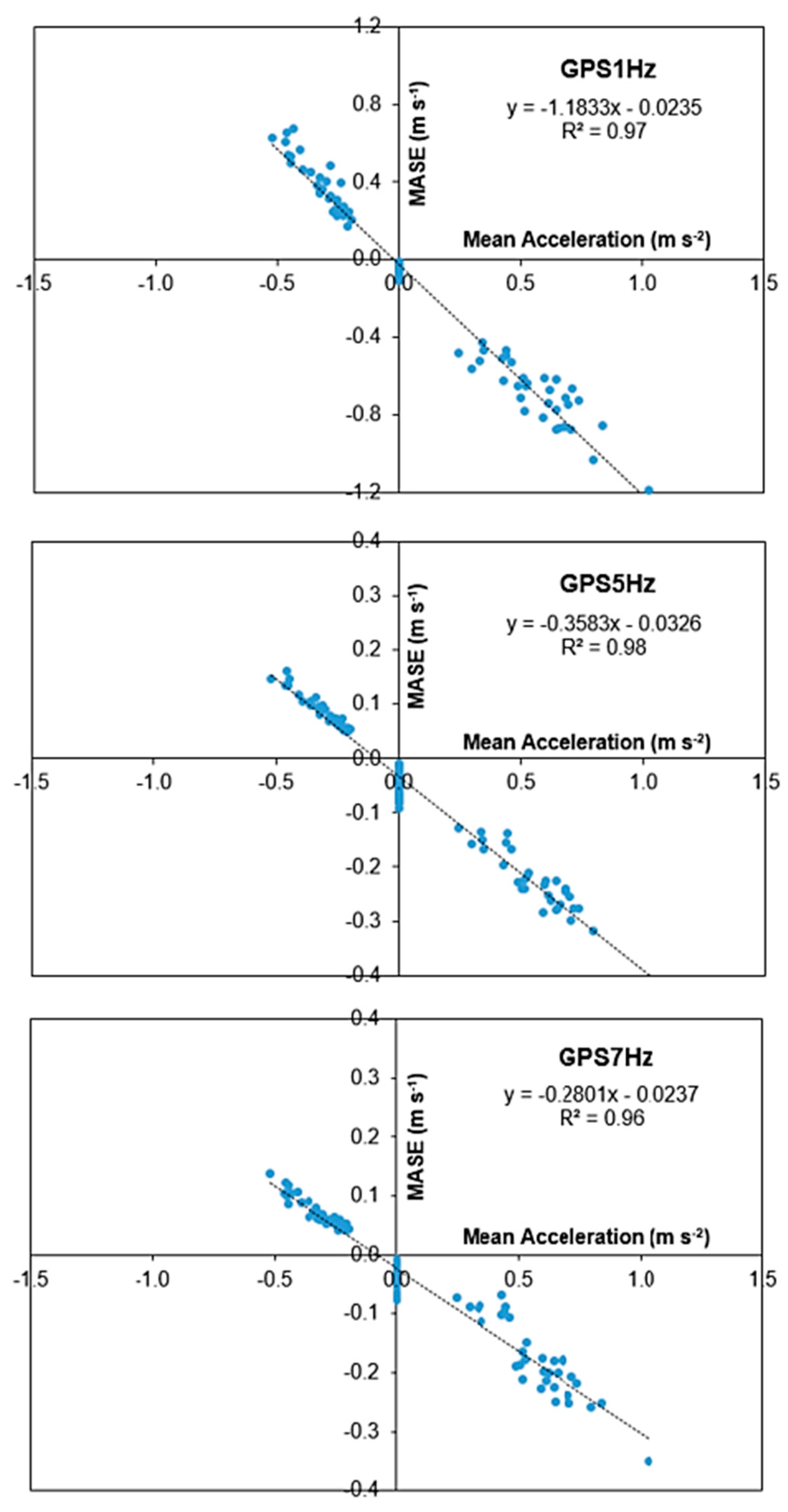
3.5. Relationship between the Speed Measurement Errors and the Acceleration Levels
A strong relationship between the mean absolute speed measurement errors and the mean acceleration levels were determined for all three GPS speed sensors (R2 = 0.97 for GPS1Hz, R2 = 0.98 for GPS5Hz, R2 = 0.96 for GPS7Hz) (Figure 7). These results indicate that the speed error values were dependent on the acceleration level. When the acceleration was higher, the errors in the speed values were also higher.
3.6. Statistical Data Analysis Results
It was found that the effect of different test days and test times did not have any statistical significance on the speed measurement error (p > 0.05). On the other hand, the differences between the error values of the three GPS speed sensors (GPS1Hz, GPS5Hz, GPS7Hz) were statistically significant (p < 0.05). Based on the results from Duncan’s multiple mean comparison test (Table 4), it was also found that the error values of the GPS speed sensors with higher update frequencies (5 and 7 Hz) were significantly lower in the increasing, constant and decreasing speed conditions compared to those with a low update frequency (1 Hz). In addition, it was observed that this difference was more prominent in cases of higher acceleration conditions (Table 4).
4. Discussion
Speed data is needed for many applications, including in agriculture. In precision agriculture, ground speed is needed to calculate and monitor crop yield in yield monitoring systems; to change the rate of the agricultural inputs in a variable rate application; to adjust the route in tractor auto steering systems; to evaluate wheel slip, traction efficiency and the fuel and energy consumption of tractors and to determine field work capacity (ha h−1). Therefore, accurate speed measurement is essential in these applications.
In recent years, GNSS or GPS receivers have had an increasing usage in velocity measurement, including in agriculture. Low-cost stand-alone GPS speed sensors with a cost in the range of several hundred US dollars are available to be utilized on farm tractors and self-propelled farm machinery. Nonetheless, information on the speed accuracy of these products, especially under different working conditions and varying speed conditions, are very limited [2,16]. One of the important advances in GNSS or GPS receivers is the higher data update frequencies, which lowers the disadvantage of the latency problem; however, research on the impact of data update frequency on the accuracy of low-cost GPS speed sensors is very limited. Some researchers have studied the speed measurement accuracy of hand-held, high-cost and high-performance GPS or GNSS units. However, we found no studies on the accuracy of the low-cost GPS units, especially on stand-alone GPS speed sensors with different data update frequencies. It is a well-known fact that the cost of equipment is a vital factor affecting its adoption rate [17,18]. Hence, this research aimed to study the influence of different data update frequencies on the accuracy of low-cost GPS speed sensors under constant and varying speed conditions.
In the present study, the mean absolute speed measurement error was found to be up to −0.09 m s−1 for GPS1Hz, −0.07 m s−1 for GPS5Hz and −0.07 m s−1 for GPS7Hz at constant speeds, depending on the speed and acceleration levels (Table 4). In the increasing speed conditions, the error values were up to −0.86 m s−1 for GPS1Hz, −0.29 m s−1 for GPS5Hz and −0.24 m s−1 for GPS7Hz, while in the decreasing speed conditions they were up to 0.57 m s−1, 0.13 and 0.11 m s−1 for GPS1Hz, GPS5Hz and GPS7Hz, respectively, depending on the speed and acceleration levels (Table 4). Thus, the GPS speed sensors showed smaller error values at constant speeds, while showing higher errors at varying speed conditions. A similar finding was reported by Witte and Wilson [21], who found that the GPS speed velocity was within ±0.2 m s−1 in 45% and ±0.4 m s−1 in 19% of the actual speed. Similarly, Vishwanathan et al. [6] determined higher error rates up to 1.79 m s−1 in increasing speed conditions. In addition, Koc et al. [22] found higher error values (up to 0.39 m s−1) in constant speed conditions. However, they did not report any information on the impact of data update frequencies on the speed measurement accuracy.
It was also determined in the present study that the GPS speed sensors slightly underestimated the speed at constant speed levels (up to −0.09 m s−1 for GPS1Hz, up to −0.07 m s−1 for GPS5Hz and up to −0.07 m s−1 for GPS7Hz) (Table 4). Similarly, Zhao et al. [23] found that the velocities from a GPS tracking device (BT-338X) were quite accurate with a tendency for underestimation, but the error between the recorded and actual velocity increased with the speed. However, the accuracy under acceleration and deceleration and the effects of the data update frequency were not studied. Beato et al. [24] reported similar findings in which the speed of male soccer players obtained from a 10 Hz GPS unit (StatSports) was lower than the reference speed obtained from video image analysis. Keskin and Say [11] reported that low-cost hand-held GPS units (1 Hz) determined speed value with high accuracy at constant speeds, but they did not study the accuracy under varying speed conditions. Fulton [25] also compared GPS-based and Radar-based speed measurements and reported that a quick acceleration produced time lags in GPS-based speeds compared to a Radar-based system, which is a similar finding to that also observed in the current study. Keskin et al. [26] also mentioned that low-cost GPS units (1 Hz) had a significant amount of delay (2–5 s), which lowers the accuracy, and reported that post processing the data improved the accuracy in varying speed conditions.
In the current study, the percent speed measurement error was found to be up to −2.3% for GPS1Hz, −1.8% for GPS5Hz and −1.4% for GPS7Hz at constant speeds, depending on the speed and acceleration levels (Table 4). In the increasing speed conditions, the error values were up to −46.5% for GPS1Hz, −15.8% for GPS5Hz and −11.5% for GPS7Hz, while in decreasing speed conditions they were up to 23.6%, 6.3% and 5.3% for GPS1Hz, GPS5Hz and GPS7Hz, respectively, depending on the speed and acceleration levels (Table 4). Al-Gaadi [27] reported higher error rates of up to 9.9% at constant speeds and up to 80.2% in varying speed conditions, but the effect of data update frequencies was not studied.
The results of the current study confirmed that the data update frequency had an important influence on reducing the speed measurement error of low-cost GPS speed sensors. Supej and Cuk [28] reported similar findings, stating that high-frequency (20 Hz) and high-cost professional GNSS receivers measured the speed more accurately, while low-cost receivers with a frequency of 1 Hz were not suitable for real-speed measurements due to their high delay time (<2.16 s). Gloersen et al. [29] tested three GNSS receivers (Garmin Forerunner 920XT 1 Hz; Catapult Optimeye S5 10 Hz; ZXY-Go differential receiver 10 Hz) for position, speed and timing, and reported that the 10 Hz receivers gave better results (0.04–0.07 m s−1) than the 1 Hz receiver (0.66 m s−1). Fu et al. [30] combined an IMU (Inertial measurement unit) with a GNSS receiver to increase its accuracy for the measurement of speed along with distance and the direction of travel.
The use of data from more than one GNSS system and the inclusion of various filtering methods could also enhance the accuracy of a GNSS-based velocity measurement. In a study, Zheng and Tang [31] reported that the accuracy of velocity prediction could be significantly improved by an integrated GPS/BDS system (BeiDou navigation satellite system), compared to a single navigation constellation system, especially under poor observation conditions. In addition, Dong et al. [32] proposed a tightly-coupled GNSS/INS (Inertial navigation system) integration with a robust sequential Kalman filter and reported a 64.7–69.4 and 30.9–47.2% improvement in the velocity and attitude data in vehicle navigation, respectively.
In the present work, a high correlation was also found between the speed measurement error and the level of acceleration (R2 > 0.95) (Figure 7). This is to say that the errors in the speed values were smaller when the acceleration was lower. The GPS speed sensors with higher update frequencies (5 Hz and 7 Hz) provided more accurate speed values compared to the lower frequency receiver (1 Hz). Hence, this study revealed that the GPS speed sensors with higher data update frequencies offer more accurate speed data, especially under increasing and decreasing speed conditions; thus, a higher update frequency is recommended for accurate speed measurements.
5. Conclusions
This research aimed to comparatively assess the effect of three different data update frequencies (1 Hz, 5 Hz and 7 Hz) on the speed measurement accuracy of three low-cost GPS speed sensors (GPS1Hz, GPS5Hz, GPS7Hz) under constant and varying speed conditions.
It was found that the speed error increased as the speed level and the acceleration level increased for all three GPS speed sensors. The GPS speed sensors provided lower speed values than the reference speed in the constant and increasing speed conditions (acceleration), while they gave higher values than the reference in the decreasing speed conditions (deceleration). The percent error was found to be up to 2.3%, 1.8% and 1.4% for GPS1Hz, GPS5Hz and GPS7Hz, respectively, at constant speeds, while at increasing speeds, the error values were up to −46.5%, −15.8% and −11.5% and at decreasing speeds, they were up to 23.6%, 6.3% and 5.3% for GPS1Hz, GPS5Hz and GPS7Hz, respectively, depending on the speed and acceleration levels. The difference between the error values of the three GPS speed sensors was statistically significant, especially for the 1 Hz frequency against the 5 and 7 Hz frequencies (p < 0.05). The error values of the GPS speed sensors with the higher update frequencies (5 and 7 Hz) were significantly lower compared to the one with a low update frequency (1 Hz), especially in cases of higher acceleration conditions; hence, the update frequency was found to be an essential factor affecting the accuracy of the low-cost GPS speed sensors. In sum, low-cost GPS speed sensors with higher update frequencies should be used for better accuracy, especially in variable speed conditions. Future studies should be carried out to investigate the effects of multiple GNSS constellations, the inclusion of accelerometers and various filters, such as the Kalman filter, on the velocity measurement accuracy of GNSS receivers.
Author Contributions
Conceptualization, M.A. and M.K.; methodology, M.A. and M.K.; software, M.K.; data curation, M.A., M.K. and Y.E.S.; writing—original draft preparation, M.A. and M.K.; writing—review and editing, Y.E.S.; investigation, M.A. and M.K.; visualization, M.K. and Y.E.S. All authors have read and agreed to the published version of the manuscript.
Funding
This research was funded by the Scientific Research Project Office (BAP) of Mustafa Kemal University, grant number 15180.
Institutional Review Board Statement
Not applicable.
Informed Consent Statement
Not applicable.
Acknowledgments
The authors thank Aysel Arslan for her help in the data collection. This paper was produced from the MS thesis of Mustafa Akkamis.
Conflicts of Interest
The authors declare no conflict of interest.
References
- Novatel. GNSS Velocity Solutions. Available online: www.novatel.com/solutions/velocity (accessed on 15 June 2021).
- Keskin, M.; Akkamis, M.; Sekerli, Y.E. An overview of GNSS and GPS based velocity measurement in comparison to other techniques. In Proceedings of the International Conference on Energy Research, Alanya, Turkey, 31 October–2 November 2018; pp. 392–404. [Google Scholar]
- Keskin, M.; Han, Y.J.; Dodd, R.B. A review of yield monitoring instrumentation applied to the combine harvesters for precision agriculture purposes. In Proceedings of the 7th International Congress on Agricultural Mechanization and Energy Proceedings, Adana, Turkey, 26–27 May 1999; pp. 426–431. [Google Scholar]
- Ess, D.; Morgan, M. The Precision-Farming Guide for Agriculturists, 2nd ed.; John Deere Publishing: Moline, IL, USA, 2003. [Google Scholar]
- Keskin, M.; Karanlik, S.; Görücü Keskin, S.; Soysal, Y. Utilization of color parameters to estimate moisture content and nutrient levels of peanut leaves. Turk. J. Agric. For. 2013, 37, 604–612. [Google Scholar] [CrossRef]
- Vishwanathan, R.; Weckler, P.R.; Solie, J.B.; Stone, M.L. Evaluation of ground speed sensing devices under varying ground surface conditions. In Proceedings of the ASAE Annual International Meeting, Tampa, FL, USA, 17–20 July 2005; pp. 1–11. [Google Scholar]
- Mullenix, D.; Fulton, J.; Winstead, A. Using GPS as a source for ground speed radar inputs. In Precision Agriculture Series Timely Information; Alabama Cooperative Extension System Publication: Auburn, AL, USA, 2010; p. 2. [Google Scholar]
- Khalilian, A.; Hale, S.A.; Hood, C.H.; Garner, T.H.; Dodd, R.B. Comparison of four ground speed measurement techniques. In Proceedings of the ASAE International Summer Meeting, Qubec City, QC, Canada, 25–28 June 1989. Paper no: 89-1040. [Google Scholar]
- Lackas, G.M.; Grisso, R.D.; Yasin, M.; Bashford, L.L. Portable data acquisition system for measuring energy requirements of soil-engaging implements. Comput. Electron. Agric. 1991, 5, 285–296. [Google Scholar] [CrossRef]
- Zhixiong, L.; Xuefeng, B.; Yiguan, L.; Jaingxue, C.; Yang, L. Wheel slip measurement in 4WD tractor based on LABVIEW. Int. J. Autom. Control Eng. 2013, 2, 113–119. [Google Scholar]
- Keskin, M.; Say, S.M. Feasibility of low-cost GPS receivers for ground speed measurement. Comput. Electron. Agric. 2006, 1, 36–43. [Google Scholar] [CrossRef]
- Doğan, S.; Temiz, M.S.; Külür, S. Real Time Speed Estimation of Moving Vehicles from Side View Images from an Uncalibrated Video Camera. Sensors 2010, 10, 4805–4824. [Google Scholar] [CrossRef] [PubMed] [Green Version]
- Freda, P.; Angrisano, A.; Gaglione, S.; Troisi, S. Time-differenced carrier phases technique for precise GNSS velocity estimation. GPS Solut. 2015, 19, 335–341. [Google Scholar] [CrossRef]
- Gaglione, S. How does a GNSS receiver estimate velocity? Inside GNSS 2015, 16, 38–41. [Google Scholar]
- Dyukov, A.; Suelynn, C.; Silcock, D. Accuracy of speed measurements using GNSS in challenging environments. Asian J. Appl. Sci. 2015, 3, 794–811. [Google Scholar]
- Dyukov, A. Development of an electronic speed measurement system for evaluating the accuracy of GNSS receivers and statistical analysis of their performance in speed measurements. Univers. J. Electr. Electron. Eng. 2016, 4, 33–50. [Google Scholar] [CrossRef] [Green Version]
- Say, S.M.; Keskin, M.; Sehri, M.; Sekerli, Y.E. Adoption of precision agriculture technologies in developed and developing countries. In Proceedings of the International Science and Technology Conference, Berlin, Germany, 17–19 July 2017; pp. 41–49. [Google Scholar]
- Barnes, A.; De Soto, I.; Eory, V.; Beck, B.; Balafoutis, A.; Sanchez, B.; Vangeyte, J.; Fountas, S.; Van der Wal, T.; Gomez-Barbero, M. Influencing factors and incentives on the intention to adopt precision agricultural technologies within arable farming systems. Environ. Sci. Policy 2019, 93, 66–74. [Google Scholar] [CrossRef]
- Akkamis, M. Determination of the Performance of GPS Speed Sensors with Different Data Update Frequencies. Master’s Thesis, Hatay Mustafa Kemal University, Antakya, Hatay, Turkey, 2018. (In Turkish with Abstract in English). [Google Scholar]
- Jeffrey, C. An Introduction to GNSS: GPS, GLONASS, Galileo and other Global Navigation Satellite Systems, 1st ed.; NovAtel Inc.: Calgary, AB, Canada, 2010. [Google Scholar]
- Witte, T.H.; Wilson, A.M. Accuracy of non-differential GPS for the determination of speed over ground. J. Biomech. 2004, 37, 1891–1898. [Google Scholar] [CrossRef] [PubMed]
- Koc, A.B.; Koc, C.; Yurtlu, Y.B.; Vatandas, M. Static and dynamic tests of a low-cost GPS receiver. In Proceedings of the 23rd National Mechanization Congress, Canakkale, Turkey, 6–8 September 2006; pp. 277–282. [Google Scholar]
- Zhao, X.; Carling, K.; Hakansson, J. Reliability of GPS based traffic data: An experimental evaluation. Available online: www.diva-portal.org/smash/get/diva2:756062/FULLTEXT03.pdf (accessed on 15 June 2021).
- Beato, M.; Bartolini, D.; Ghia, G.; Zamparo, P. Accuracy of a 10 Hz GPS unit in measuring shuttle velocity performed at different speeds and distances (5–20 M). J. Hum. Kinet. 2016, 54, 15–22. [Google Scholar] [CrossRef] [PubMed] [Green Version]
- Fulton, J.; Darr, M.; Taylor, R.; Shearer, S. Proper implementation of precision agricultural technologies for conducting on-farm research. In Proceedings of the 10th International Conference on Precision Agriculture, Monticello, IL, USA, 18–21 July 2010. [Google Scholar]
- Keskin, M.; Sekerli, Y.E.; Kahraman, S. Performance of two low-cost GPS receivers for ground speed measurement under varying speed conditions. Precis. Agric. 2017, 18, 264–277. [Google Scholar] [CrossRef]
- Al-Gaadi, K.A. Testing the accuracy of autonomous GPS in ground speed measurement. J. Appl. Sci. 2005, 5, 1518–1522. [Google Scholar] [CrossRef]
- Supej, M.; Cuk, I. Comparison of global navigation satellite system devices on speed tracking in road (Tran) SPORT applications. Sensors 2014, 14, 23490–23508. [Google Scholar] [CrossRef] [PubMed] [Green Version]
- Gloersen, O.; Kocbach, J.; Gilgien, M. Tracking performance in endurance racing sports: Evaluation of the accuracy offered by three commercial GNSS receivers aimed at the sports market. Front. Physiol. 2018, 9, 1425. [Google Scholar] [CrossRef] [PubMed] [Green Version]
- Fu, W.; Shupeng, H.; Changhai, L.; You, L.; Shuxia, G.; Junxiong, Z. Development and test of GNSS/IMU-based speed measurement device for agricultural machinery. In Computer and Computing Technologies in Agriculture XI; Li, D., Zhao, C., Eds.; Springer: Cham, Switzerland, 2019; pp. 440–451. [Google Scholar] [CrossRef] [Green Version]
- Zheng, K.; Tang, L. Performance assessment of BDS and GPS/BDS velocity estimation with stand-alone receiver. J. Navig. 2016, 69, 869–882. [Google Scholar] [CrossRef] [Green Version]
- Dong, Y.; Wang, D.; Zhang, L.; Li, Q.; Wu, J. Tightly coupled GNSS/INS integration with robust sequential Kalman filter for accurate vehicular navigation. Sensors 2020, 20, 561. [Google Scholar] [CrossRef] [PubMed] [Green Version]
Figure 1.
A schematic view of a commercially-available low-cost GPS speed sensor.
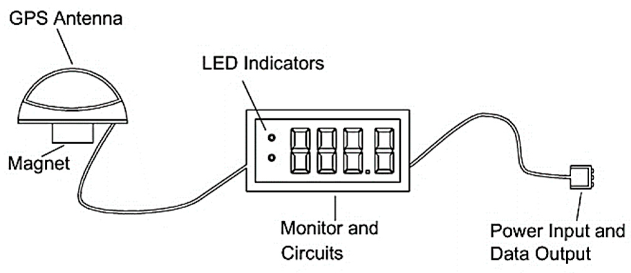
Figure 2.
Hardware used in the study ((1) Three GPS speed sensors, (2) DAQ card and other circuitry, (3) Optical shaft encoder and computer) (drawing not to scale).
Figure 2.
Hardware used in the study ((1) Three GPS speed sensors, (2) DAQ card and other circuitry, (3) Optical shaft encoder and computer) (drawing not to scale).
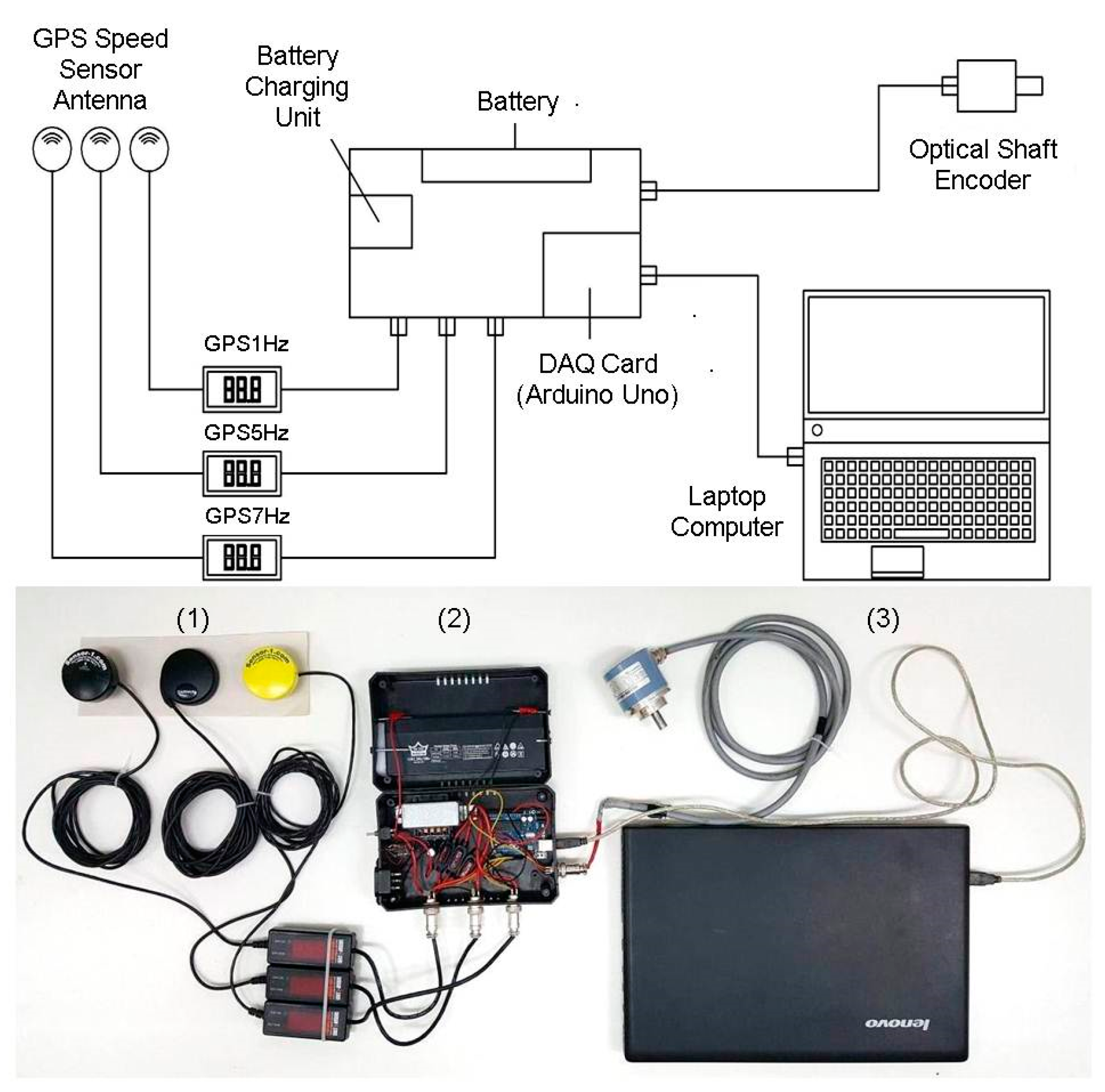
Figure 3.
A view of the hardware mounted on the farm tractor.

Figure 4.
Calculation of the mean acceleration and the mean speed difference (error) values.
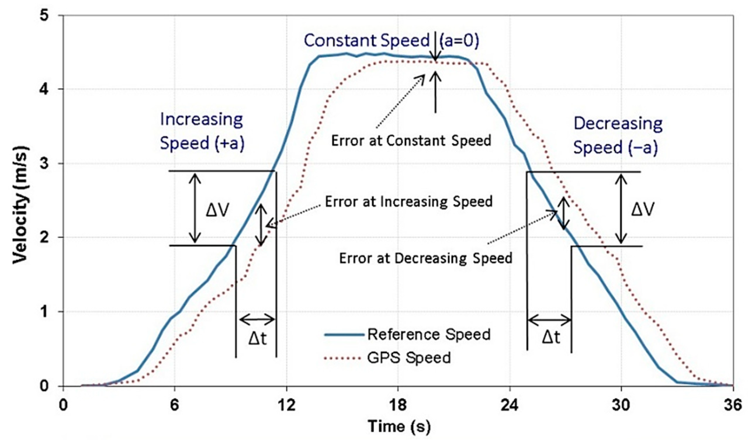
Figure 5.
Comparison of the speed data from the three GPS speed sensors to the reference speed in low-speed levels (a) and high-speed levels (b).
Figure 5.
Comparison of the speed data from the three GPS speed sensors to the reference speed in low-speed levels (a) and high-speed levels (b).

Figure 6.
Mean absolute speed errors of the three GPS speed sensors at increasing (a), constant (b) and decreasing (c) speed conditions (different scales were used for y-axis).
Figure 6.
Mean absolute speed errors of the three GPS speed sensors at increasing (a), constant (b) and decreasing (c) speed conditions (different scales were used for y-axis).
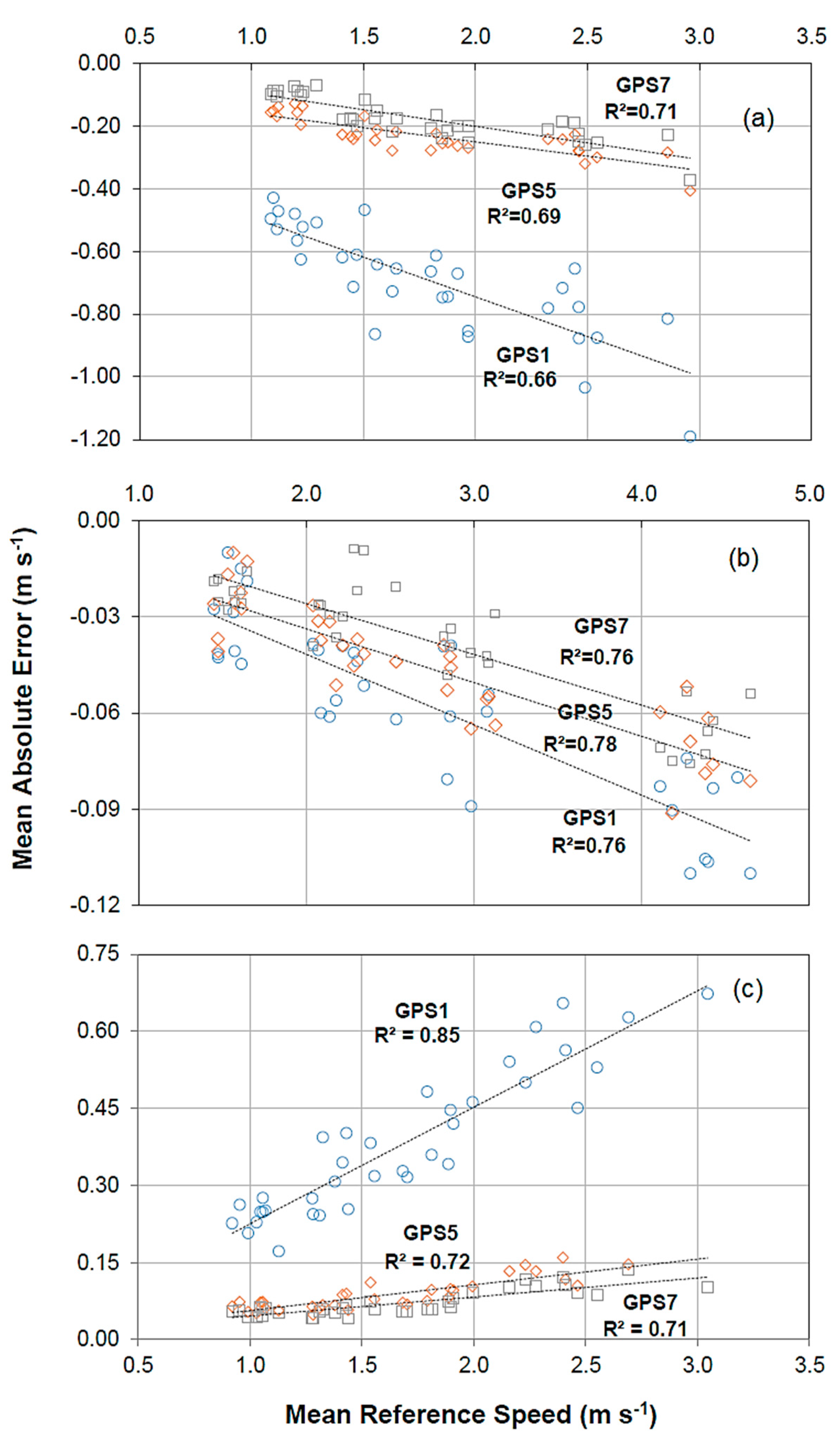
Figure 7.
Relationship between the mean absolute speed errors (MASEs) and the mean acceleration levels for the three GPS speed sensors with different data update frequencies.
Figure 7.
Relationship between the mean absolute speed errors (MASEs) and the mean acceleration levels for the three GPS speed sensors with different data update frequencies.

Table 1.
Some technical features of the three GPS speed sensors, optical shaft encoder and DAQ card used in the study.
Table 1.
Some technical features of the three GPS speed sensors, optical shaft encoder and DAQ card used in the study.
| Device | Make and Model | Technical Features |
|---|---|---|
| GPS1Hz | Sensor-1 GPSMD-1 (Princeton, KS, USA) | Data update frequency: 1 Hz Output signal: 57 Hz mp h−1 Signal type: Square pulse (0–12 V) |
| GPS5Hz | Sensor-1 GPSMD-5 (Princeton, KS, USA) | Data update frequency: 5 Hz Output signal: 57 Hz mp h−1 Signal type: Square pulse (0–12 V) |
| GPS7Hz | Sensor-1 GPSMD-7 (Princeton, KS, USA) | Data update frequency: 7 Hz Output signal: 57 Hz mp h−1 Signal type: Square pulse (0–12 V) |
| Optical Shaft Encoder | Wachendorff WDG 58B-1000 (Geisenheim, Germany) | Power input: 5 VDC Output signal: 1000 Hz/revolution Signal type: Square pulse (0–5 V) |
| DAQ card | Arduino Uno R3 (Somerville, MA, USA) | Power input: 5 VDC (USB) Digital channels: 14 (6 PWM) Analog channels: 6 Memory: 32 KB |
Table 2.
Some details of the speed measurement tests.
| Criteria | Details of Test Criteria |
|---|---|
| Test days (three days) | 24 April 2018 25 April 2018 26 April 2018 |
| Test times (three times) | Morning (between 9:00 and 11:00) Noon (between 13:00 and 15:00) Evening (between 17:00 and 19:00) |
| Speed levels (four levels) | Gear 1 (~1.40–1.80 m s−1) Gear 2 (~2.00–2.50 m s−1) Gear 3 (~2.70–3.20 m s−1) Gear 4 (~4.30–5.20 m s−1) |
| Number of replications | Four replications at each speed level |
| Total number of tests | 144 (3 days × 3 times × 4 speeds × 4 replications) |
Table 3.
Data related to the GPS signal quality at the test time.
| Day and Time | Weather | Number of Satellites | EHPE * (m) | EVPE * (m) | HDOP * | VDOP * | |
|---|---|---|---|---|---|---|---|
| Day 1 Morning | Partly cloudy | Min: Max: Mean ± SD: | 5 8 6.7 ± 0.54 | 3.2 5.5 3.7 ± 0.46 | 3.5 5.9 4.0 ± 0.42 | 1.1 2.9 1.5 ± 0.38 | 1.0 2.7 1.5 ± 0.47 |
| Day 1 Noon | Partly cloudy | Min: Max: Mean ± SD: | 7 8 7.3 ± 0.22 | 2.8 3.4 3.0 ± 0.18 | 5.1 6.8 5.7 ± 0.50 | 1.4 1.7 1.6 ± 0.10 | 2.0 2.8 2.3 ± 0.17 |
| Day 1 Evening | Clear, sunny | Min: Max: Mean ± SD: | 7 7 7.0 ± 0.01 | 2.6 3.7 2.8 ± 0.29 | 3.8 4.8 4.0 ± 0.22 | 1.0 1.7 1.1 ± 0.09 | 1.3 1.9 1.4 ± 0.10 |
| Day 1 Morning | Partly cloudy | Min: Max: Mean ± SD: | 5 6 5.1 ± 0.24 | 2.6 3.0 2.9 ± 0.07 | 5.4 6.4 5.9 ± 0.26 | 1.3 2.0 1.8 ± 0.12 | 1.0 3.1 1.7 ± 0.62 |
| Day 1 Noon | Partly cloudy | Min: Max: Mean ± SD: | 7 8 7.5 ± 0.50 | 2.7 3.3 3.0 ± 0.18 | 4.3 6.8 5.1 ± 0.79 | 1.1 1.8 1.4 ± 0.19 | 1.4 3.1 2.0 ± 0.43 |
| Day 1 Evening | Partly cloudy | Min: Max: Mean ± SD: | 7 8 7.5 ± 0.50 | 2.3 3.0 2.6 ± 0.26 | 3.4 4.2 3.7 ± 0.31 | 1.1 1.3 1.2 ± 0.05 | 1.7 2.0 1.8 ± 0.08 |
| Day 1 Morning | Clear, sunny | Min: Max: Mean ± SD: | 6 10 8.5 ± 0.90 | 3.0 6.8 3.9 ± 1.08 | 3.0 5.8 3.7 ± 0.77 | 0.8 1.9 1.1 ± 0.36 | 1.1 1.9 1.2 ± 0.23 |
| Day 1 Noon | Clear, sunny | Min: Max: Mean ± SD: | 7 8 7.9 ± 0.32 | 2.5 3.3 2.6 ± 0.17 | 3.7 6.0 4.0 ± 0.29 | 0.9 1.3 1.0 ± 0.08 | 1.1 2.0 1.2 ± 0.14 |
| Day 1 Evening | Clear, sunny | Min: Max: Mean ± SD: | 7 10 7.3 ± 0.49 | 2.4 3.4 2.6 ± 0.27 | 3.4 5.4 3.7 ± 0.44 | 0.9 1.3 1.1 ± 0.11 | 1.2 2.0 1.7 ± 0.28 |
* EHPE, Estimated horizontal position error (m); EVPE, Estimated vertical position error (m); HDOP, Horizontal dilution of precision; VDOP, Vertical dilution of precision; SD, Standard Deviation.
Table 4.
Mean speed error values of the three GPS speed sensors.
| Acceleration | Speed Level | GPS Speed Sensor | Mean Acceleration (m s−2) | Mean Speed (m s−1) | Mean Absolute Error (m s−1) * | Mean Percent Error (%) * |
|---|---|---|---|---|---|---|
| a = + (Increasing speed conditions) | Gear 1 | GPS1Hz GPS5Hz GPS7Hz | 0.38 | 1.17 | −0.51 ± 0.06 a −0.15 ± 0.02 b −0.09 ± 0.01 c | −42.3 ± 3.61 a −12.8 ± 2.39 b −7.5 ± 1.39c |
| Gear 2 | GPS1Hz GPS5Hz GPS7Hz | 0.63 | 1.50 | −0.66 ± 0.12 a −0.23 ± 0.03 b −0.17 ± 0.03 b | −46.5 ± 9.79 a −15.8 ± 2.44 b −11.5 ± 1.91 b | |
| Gear 3 | GPS1Hz GPS5Hz GPS7Hz | 0.68 | 1.86 | −0.73 ± 0.10 a −0.25 ± 0.02 b −0.21 ± 0.03 b | −40.3 ± 8.16 a −14.4 ± 1.80 b −11.4 ± 1.57 b | |
| Gear 4 | GPS1Hz GPS5Hz GPS7Hz | 0.66 | 2.55 | −0.86 ± 0.16 a −0.29 ± 0.06 b −0.24 ± 0.05 b | −34.3 ± 6.61 a −11.2 ± 1.49 b −9.4 ± 1.60 b | |
| a = 0 (Constant speed conditions) | Gear 1 | GPS1Hz GPS5Hz GPS7Hz | 0 | 1.55 | −0.03 ± 0.01 a −0.03 ± 0.01 a −0.02 ± 0.01 a | −2.0 ± 0.84 a −1.6 ± 0.69 a −1.4 ± 0.26 a |
| Gear 2 | GPS1Hz GPS5Hz GPS7Hz | 0 | 2.18 | −0.05 ± 0.01 a −0.04 ± 0.01 a −0.03 ± 0.01 b | −2.2 ± 0.48 a −1.7 ± 0.32 b −1.2 ± 0.52 c | |
| Gear 3 | GPS1Hz GPS5Hz GPS7Hz | 0 | 2.91 | −0.06 ± 0.02 a −0.05 ± 0.01 a −0.04 ± 0.01 b | −2.3 ± 0.72 a −1.8 ± 0.25 b −1.3 ± 0.28 c | |
| Gear 4 | GPS1Hz GPS5Hz GPS7Hz | 0 | 4.36 | −0.09 ± 0.02 a −0.07 ± 0.01 b −0.07 ± 0.01 b | −2.2 ± 0.42 a −1.5 ± 0.42 b −1.4 ± 0.36 b | |
| a = − (Decreasing speed conditions) | Gear 1 | GPS1Hz GPS5Hz GPS7Hz | −0.24 | 1.03 | 0.24 ± 0.03 a 0.06 ± 0.01 b 0.05 ± 0.01 b | 23.3 ± 3.46 a 6.3 ± 1.02 b 5.3 ± 0.77 b |
| Gear 2 | GPS1Hz GPS5Hz GPS7Hz | −0.26 | 1.38 | 0.31 ± 0.06 a 0.07 ± 0.01 b 0.05 ± 0.01 b | 22.5 ± 4.25 a 5.1 ± 0.83 b 3.9 ± 0.61 b | |
| Gear 3 | GPS1Hz GPS5Hz GPS7Hz | −0.32 | 1.80 | 0.39 ± 0.06 a 0.09 ± 0.02 b 0.07 ± 0.01 b | 22.0 ± 3.07 a 5.0 ± 0.96 b 3.8 ± 0.60 b | |
| Gear 4 | GPS1Hz GPS5Hz GPS7Hz | −0.44 | 2.47 | 0.57 ± 0.07 a 0.13 ± 0.02 b 0.11 ± 0.02 b | 23.6 ± 3.15 a 5.2 ± 1.30 b 4.4 ± 0.73 b |
* Different letters (a, b, c) in each column indicate significant differences for each speed gear level (p < 0.05).
Publisher’s Note: MDPI stays neutral with regard to jurisdictional claims in published maps and institutional affiliations. |
© 2021 by the authors. Licensee MDPI, Basel, Switzerland. This article is an open access article distributed under the terms and conditions of the Creative Commons Attribution (CC BY) license (https://creativecommons.org/licenses/by/4.0/).
Share and Cite
MDPI and ACS Style
Akkamis, M.; Keskin, M.; Sekerli, Y.E. Comparative Appraisal of Three Low-Cost GPS Speed Sensors with Different Data Update Frequencies. AgriEngineering 2021, 3, 423-437. https://0-doi-org.brum.beds.ac.uk/10.3390/agriengineering3020028
AMA Style
Akkamis M, Keskin M, Sekerli YE. Comparative Appraisal of Three Low-Cost GPS Speed Sensors with Different Data Update Frequencies. AgriEngineering. 2021; 3(2):423-437. https://0-doi-org.brum.beds.ac.uk/10.3390/agriengineering3020028
Chicago/Turabian StyleAkkamis, Mustafa, Muharrem Keskin, and Yunus Emre Sekerli. 2021. "Comparative Appraisal of Three Low-Cost GPS Speed Sensors with Different Data Update Frequencies" AgriEngineering 3, no. 2: 423-437. https://0-doi-org.brum.beds.ac.uk/10.3390/agriengineering3020028