

Smart Design of Hip Replacement Prostheses Using Additive Manufacturing and Machine Learning Techniques


Department of Engineering, University of Messina, Contrada di Dio, 98166 Messina, Italy
*
Author to whom correspondence should be addressed.
Prosthesis 2024, 6(1), 24-40; https://0-doi-org.brum.beds.ac.uk/10.3390/prosthesis6010002
Submission received: 29 September 2023
/
Revised: 1 December 2023
/
Accepted: 7 December 2023
/
Published: 20 December 2023
(This article belongs to the Special Issue State of Art in Hip and Knee Replacement)
Abstract
:The field of additive manufacturing, particularly 3D printing, has ushered in a significant transformation in the realm of joint arthritis treatment through prosthetic surgery. This innovative technology allows for the creation of bespoke prosthetic devices that are tailored to meet the specific needs of individual patients. These devices are constructed using high-performance materials, including titanium and cobalt-chrome alloys. Nevertheless, the routine physical activities of patients, such as walking, sitting, and running, can induce wear and tear on the materials comprising these prosthetic devices, subsequently diminishing their functionality and durability. In response to this challenge, this research has endeavored to leverage novel techniques. The primary focus of this study lies in the development of an algorithm designed to optimize hip replacement procedures via the mechanical design of the prosthesis. This optimization process exploits the capabilities of machine learning algorithms, multi-body dynamics, and finite element method (FEM) simulations. The paramount innovation in this methodology is the capacity to design a prosthetic system that intricately adapts to the distinctive characteristics of each patient (weight, height, gait cycle). The primary objective of this research is to enhance the performance and longevity of prosthetic devices by improving their fatigue strength. The evaluation of load distribution on the prosthetic device, facilitated by FEM simulations, anticipates a substantial augmentation in the useful life of the prosthetic system. This research holds promise as a notable advancement in prosthetic technology, offering a more efficacious treatment option for patients suffering from joint arthritis. The aim of this research is to make meaningful contributions to the enhancement of patient quality of life and the long-term performance of prosthetic devices.
1. Introduction
The World Health Organization (WHO) estimates that approximately 1.5 million total hip replacement (THR) surgeries are performed each year globally, with over 500,000 in the US and around 100,000 in Russia [1]. Since their introduction in 1975, the use of Burch–Schneider cages has steadily increased, with more than 125,000 cages implanted by 2006. The need for primary THR causes an increase in the need for revision THR. In most clinical cases, bone mass or fragment loss is found during revision surgery [2,3].
According to Deere et al. [4], the THR has a follow-up of about 10 years, which involves a revision of the prosthesis to check if there are any wear or other problems.
The use of additive manufacturing (AM) techniques in prosthetic surgery has revolutionized the clinical treatment of patients with joint arthritis, rheumatoid arthritis, post-traumatic arthrosis, and congenital dysplasia. Three-dimensional printing has made it possible to create customized prostheses based on the individual needs of patients using high-performance materials such as 316L stainless steel [5]. However, wear caused by regular activities such as walking, sitting, or running can lead to deterioration of the materials used in the joint [6,7,8]. To overcome this problem, researchers are increasingly turning to more advanced materials [9,10,11] and numerical techniques, such as the finite element method (FEM), to improve the functionality and lifespan of prostheses [12,13,14,15,16,17,18,19,20]. Human models are also used to simulate the influence of prosthetic design on human comfort and biomechanics [21,22,23,24]. Researchers are increasingly shifting their focus towards developing models that simulate the entire body rather than being restricted to small and specific segments [25]. Multibody simulations have found excellent application in sports biomechanics and in the analysis of the interaction between human exoskeletons [26,27]. Motion capture, also known as mocap, is a technology that captures the movement of objects or people. The potential benefits of motion capture include the ability to accurately capture complex movements for use in various applications such as animation, video games, and virtual reality. Additionally, motion capture enables the creation of realistic movements for characters in a more efficient and cost-effective manner than traditional animation techniques. However, motion capture also has several limitations. One of the main limitations is the requirement for specialized equipment and a controlled environment, which can be expensive and time-consuming to set up. Additionally, motion capture relies on markers or sensors attached to the subject, which can limit the range of motion and restrict natural movements. Finally, motion capture data may require significant post-processing to be usable in the desired application, which can be time-consuming and complex. Markerless motion capture is a type of motion capture that uses computer vision and machine learning algorithms to track the movements of objects or people without the use of markers or sensors. Compared to traditional motion capture, markerless motion capture offers several advantages:
- Flexibility: Markerless motion capture does not require the use of markers or sensors, which allows for greater freedom of movement and a more natural capture of movements.
- Cost-effectiveness: Markerless motion capture eliminates the need for specialized equipment and the associated costs, making it a more cost-effective solution for many applications.
- Easy setup: Markerless motion capture can be set up in a more straightforward manner than traditional motion capture, reducing the time and effort required for setup.
- Portability: Markerless motion capture can be performed on location, eliminating the need for a controlled environment, which can be useful in various real-world applications such as sports analysis or rehabilitation.
The current research aims to develop an algorithm that optimizes hip replacement mechanically using a machine learning algorithm coupled with multibody and FEM simulations. The innovative aspect is represented by using artificial intelligence to evaluate human kinematics, a humanoid model in the ADAMS® environment, and the FEM model, which allows for the optimization of the prosthesis and suggests the best geometry. This model extracts loads from the patient and uses them to design a dedicated prosthesis specifically for the subject. This prosthesis is manufactured using additive manufacturing. This algorithm is not based on analyzing different subjects but on a custom design philosophy, where the prosthesis shape is optimized based on the loads acting on the system. The method is unique and tailored to the specific subject.
2. Materials and Methods
The musculoskeletal and nervous systems play a crucial role in the act of walking for humans. The forces and movements generated by the lower limbs during walking are transmitted through various joints, ligaments, and muscles to the trunk of the body. Additionally, the movement of the upper limbs, the spinal joints, and the trunk generate inertial forces that help balance the body, working in conjunction with the forces generated by the lower limbs to achieve the desired movement pattern [30,31]. Walking was specifically chosen as the movement to optimize prosthetics for, as it is a common and essential activity in daily life. To optimize the hip prosthesis, an algorithm was established consisting of five phases: motion capture, joint angle extraction, creation of a human model, finite element analysis of the prosthesis, and optimization of results using the gradient descent method.
2.1. Characterizing Human Movement through Joint Angle Extraction Using OpenPose
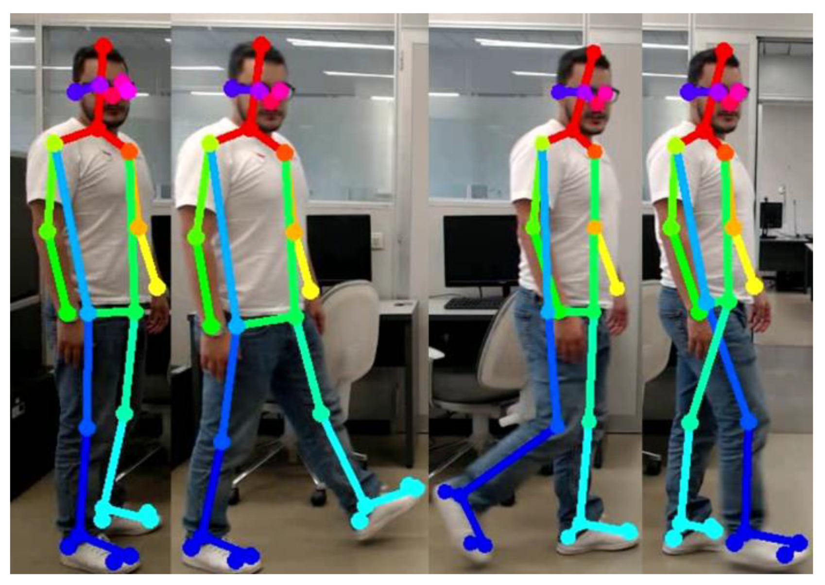
Human pose estimation refers to the task of determining the positions of a subject’s joints directly from a digital image. This process requires high precision in the detection and identification of human joints [32,33,34,35,36]. There are two main approaches to pose estimation: top-down and bottom-up. Top-down approaches [37,38,39,40] have a computational cost that is proportional to the number of individuals present in the image, making them less efficient when a large number of people are present. On the contrary, bottom-up approaches provide resilience in the early stages of involvement and possess the capability to reduce the runtime complexity independently of the number of individuals in the image. However, these methods do not leverage global contextual cues from other body parts or different individuals. In practice, previous bottom-up methods [41,42] do not maintain the efficiency gains, as the final analysis requires a costly global inference. The present study evaluated a model, OpenPose, for determining the subject’s pose while walking. OpenPose [39,43,44] is a bottom-up, multi-person human pose detection library that detects key points on the human body, feet, hands, and face in single images. It can detect 135 vital points of the body from a digital image through the use of a single convolutional neural network (CNN) for both key point detection and association. A numerical score between 0 and 1 is assigned to each key point, with a higher score indicating a greater level of confidence in the estimated key point. OpenPose was trained to produce three different pose patterns, distinguished by the number of points identified. The first pose pattern, the MPI (Max Plank Institute), can estimate a total of 15 key points. The COCO (Common Objects in Context) pose pattern can estimate a total of 18 points, while the BODY_25 pose pattern can estimate a total of 25 points. Within the exposed pose patterns, the most comprehensive is BODY_25, which, in addition to the key points estimated by the MPI and COCO models, includes descriptors for the feet and pelvic center.
As previously reported in the literature [45,46], the OpenPose model has been found to possess the highest accuracy parameters, making it more precise than the default BODY_25 model and resulting in a reduction of false positives. The model also deviates from MPI in its definition of key points, specifically in the evaluation of head and neck key points, and eliminates the key points of the body’s neck and mid-hip found in the BODY_25 model. To begin the evaluation process, the first step implemented was the classification of all points captured by the algorithm. To capture the subject’s movement, an action camera was positioned in front of the subject (Table 1).
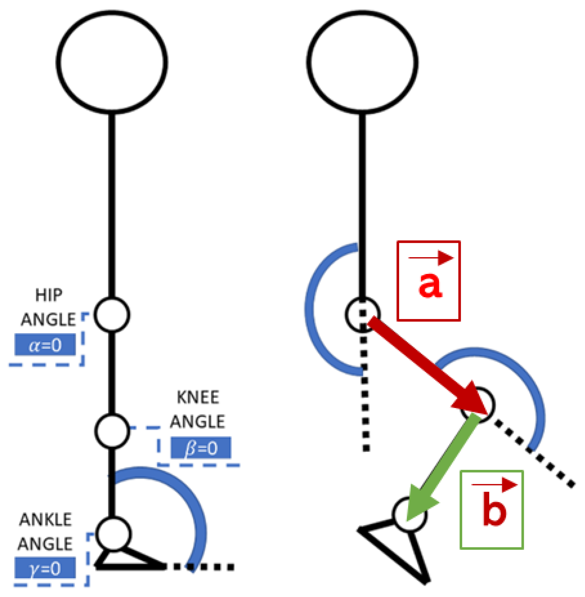
In the experiment, the subject stood in front of the camera with a vertical posture, having an initial pose defined by an angle of 180 degrees between the trunk and legs. The subject’s walking exercise was recorded with a video camera, and the OpenPose algorithm was utilized to extract the pose. As described in [47], the knee angle was determined through vector point calculations.
2.2. Construction of Hip-Knee-Ankle Vectors for Joint Angle Calculation in Motion Capture
The process of identifying and calculating vectors from the hip, knee, and ankle coordinates extracted from the pose data is depicted in Figure 1. The joint angles were then calculated according to Viswakumar et al. [47], and the resulting angle descriptions in terms of time were used to generate motion laws in Adams.
At the moment of departure, where both feet are in support, as depicted in Figure 2, the right foot is in a stance position and the left foot is in a swing position, it is evident that the movement has started. Finally, the end of the cycle and the beginning of the next cycle are shown (Figure 2). As outlined above, the defining parameters of walking were calculated (Table 2).
2.3. Bipedal Gait Cycle Load Calculus by Using the Human Mutibody Model
The growth of virtual human models has been driven by the need to understand the biomechanical aspects of movements and their impact on comfort. Multibody simulations, according to Young et al. [48], are widely used in sports biomechanics [26], as they consider the movement of the entire body as a collection of interconnected joints. The critical steps in biomechanical movement analysis are defining the dynamic equation of human movement and acquiring the dynamic parameters of human action. The proposed model in this paper is divided into three main sections: upper limbs, torso, and lower limbs. The dummy has 32 (Table 3) dimensions, as described by Cheng et al. [25]. The model, as described above, provides for the selection of two macrotypes of humanoids (Figure 3).
In the first case, all 32 dimensions are known as they represent human percentiles. In the second case, the subject’s dimensions were evaluated based on the data in Table 4 and determined through linear regression using known data.
where represents the body dimension to be calculated, G is gender, R is race, is height, is seated height, and is the weight. The dimensions in both cases were retrieved from the ANSUR II database [49] in the 2012 US Army Anthropometric Survey. As for the creation of the mannequin with human percentiles, the 32 dimensions come from the calculation of the percentiles. Table 4 represents the parameters measured on the subject taken into consideration for the human subject under examination. By employing these parameters and regression lines, the model implemented within the Adams software effectively estimated the dimensions of the human subject, thereby generating a mannequin consistent with the subject’s anthropometric dimensions and possessing comparable masses and inertias.
Once the Adams mannequin model is defined, as described earlier, the state variables are established. The set of variables reflects the variations in angle in the three components of the 25 points identified by the motion capture algorithm (OpenPose). At the same time, the forces along the three axes of rotation of the spherical joint located in the hip are calculated as the output, with their three components.
The system acquires real-time positional changes of all twenty-five joints in Cartesian coordinates (in CSV format). As described in [47], it calculates the angular variations of each joint of the human body using previously defined equations. Subsequently, the temporal signals representing angular changes in the joints are employed as state variables to actuate the movements of the mannequin created within the Adams environment (Figure 4).
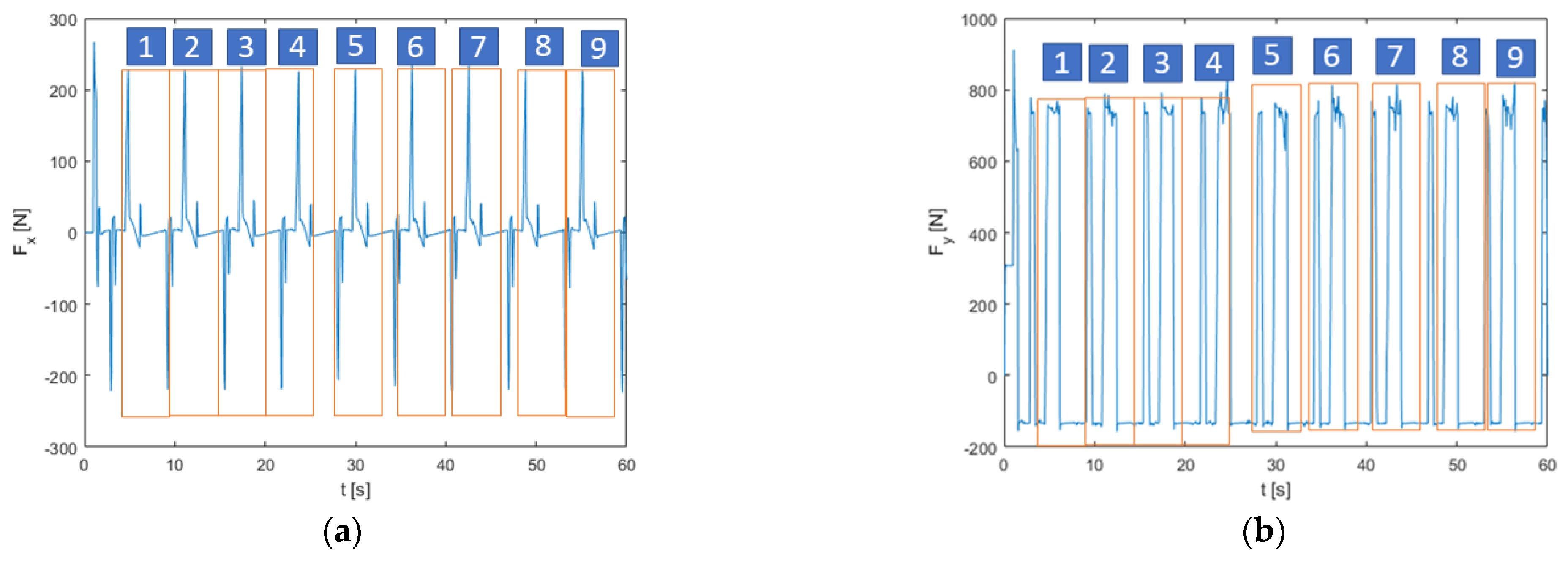
A 60 s gait was calculated, and nine cycles were extracted from it. The values of the reaction forces calculated at the hip spherical joint were extracted from the multibody model. The calculated outputs will be utilized as loads acting on the prosthesis to optimize its shape (Figure 5).
2.4. Shape Optimization Algorithm
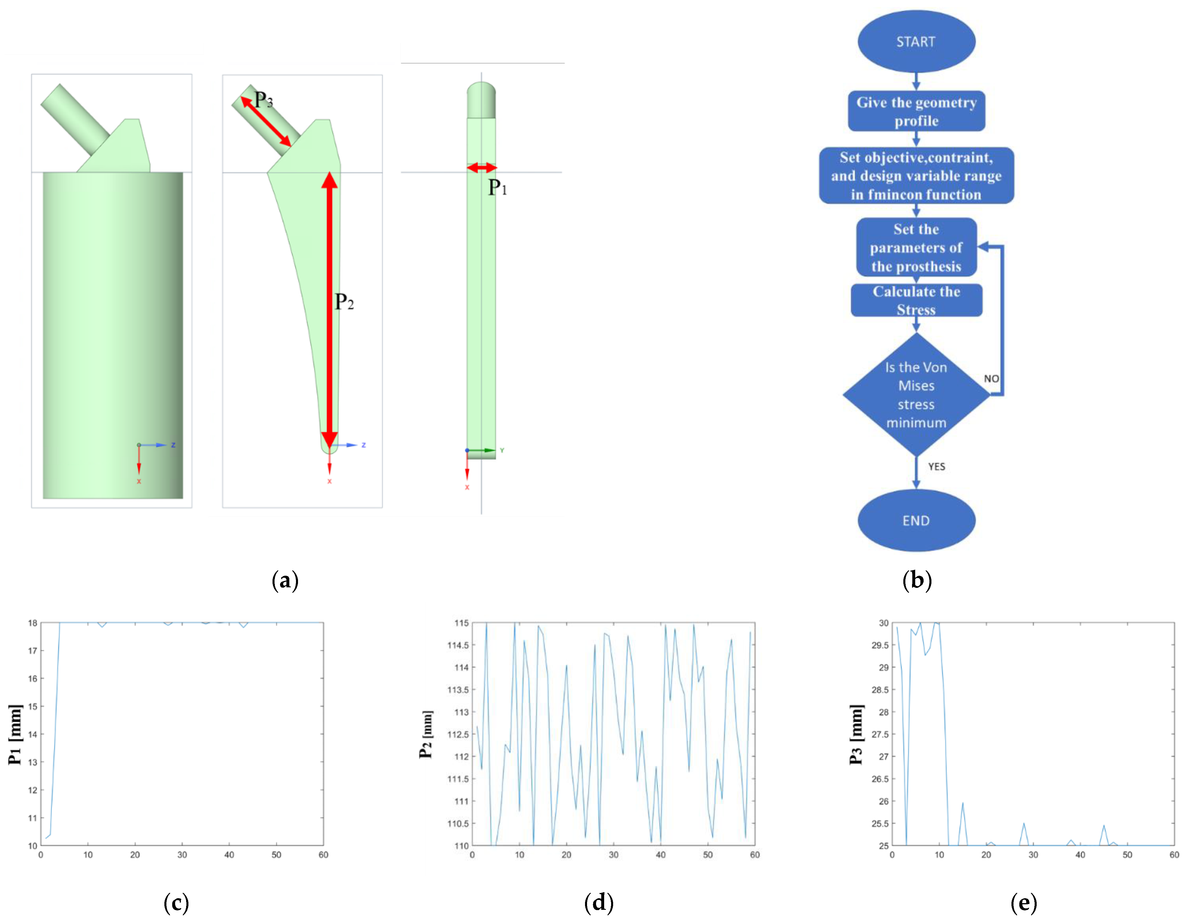
The final phase of the analysis involves the prosthesis optimization process, which involves the FMINCON algorithm, a MATLAB® function that finds the minimum of a scalar function of multiple variables within a region defined by linear constraints and bounds. A schematic representation of the prosthesis is reported in Figure 6a, while the process is outlined in Figure 6b. Three distinct geometric parameters were identified for the prosthesis study: the thickness of the prosthesis, P1 (Figure 6c), the length of the prosthesis, P2 (Figure 6d), and the length of the prosthesis neck, P3 (Figure 6e). The dimensions of the prosthesis under analysis were obtained by some models of prosthesis from Lima Corporate S.p.a., an Italian prosthesis manufacturer, with the subject’s measurements taken into account to find the best fitting option. The catalog provided a range of variations for the primary dimensions, allowing for a more precise and tailored selection. Careful consideration was given to the subject’s individual needs to ensure that the chosen prosthesis would provide a comfortable and functional fit. The chosen specifications were then used to guide the production process, ensuring the final result would meet the subject’s unique requirements.
Each iteration cycle involved changing one or more parameters simultaneously using the FMINCON function. After obtaining the new parameter values, the CAD of the prosthesis is recreated, and the new geometry is simulated with FE analysis. The initial solution, which included specific prosthetic parameters for the subject under investigation, was identified as the target. Subsequently, each new solution was compared against this target, and if the solution from the “i”th iteration results in a lower value than the target, it replaces the target. The iteration process continues until the minimum of the objective function is reached.
2.5. FEM Analysis in Detail
The calculation of stress on the prosthesis during the optimization phase involved determining the maximum load it would be subjected to during the walking cycle. The loads calculated from the multi-body system were used as inputs in the FEM model. The model was set up as follows:
- Constraints: The constraints were of the fixed type, applied to the bottom surface of the prosthesis.
- Loads: Concentrated loads were applied to the horizontal surface of the prosthesis neck.
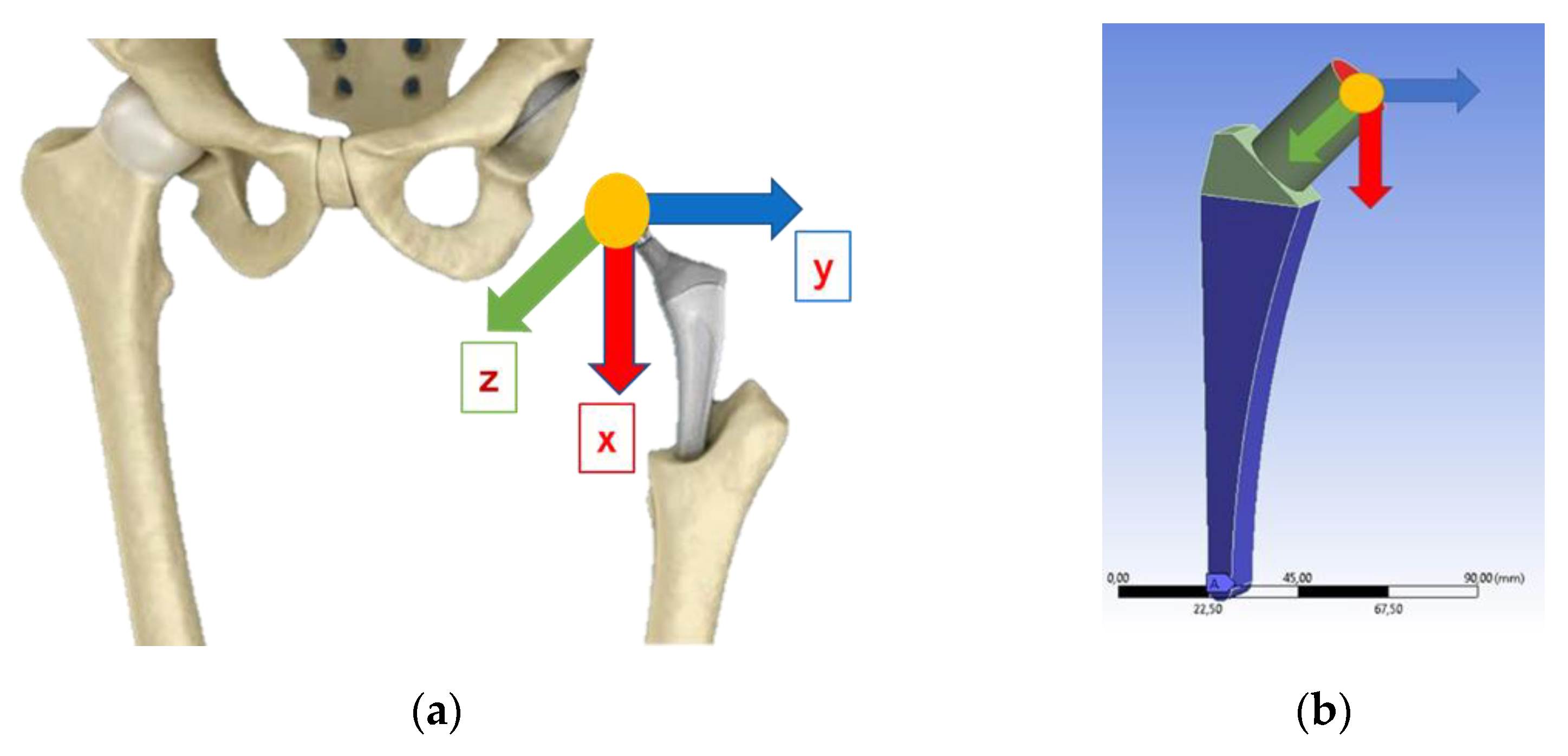
The constraints are depicted in blue, while the loads are visualized using different colors based on their lines of action along each axis (Figure 7). The Ansys Workbench simulation software with a mesh of SOLID187 element type was adopted.
A convergence analysis was conducted based on the system displacement values produced at the output. To ensure accurate results, the mesh density was incrementally increased until a displacement value of 2% or less relative to the previous simulation was achieved, as shown in Figure 8.
The prosthesis was designed using stainless steel (AISI 316L), which is suitable for custom hip prosthesis production [50,51]. Samples of the steel were obtained according to the geometry “Continuous radius between end” of the ASTM E 466 standard and subjected to stress-controlled fatigue tests to assess the fatigue strength of an MTS810 servohydraulic testing machine (maximum load force 250 kN, testing frequency 10 Hz). The mechanical properties of AISI 316L are reported in Table 5.
The S-N curve with stress ratio was identified for the steel (Figure 9).
As reported in [52,53], the Basquin equation was adopted to fit the experimental fatigue data.
where is the stess amplitude, is the number of cycles to failure, and A and B are fitting coefficients.
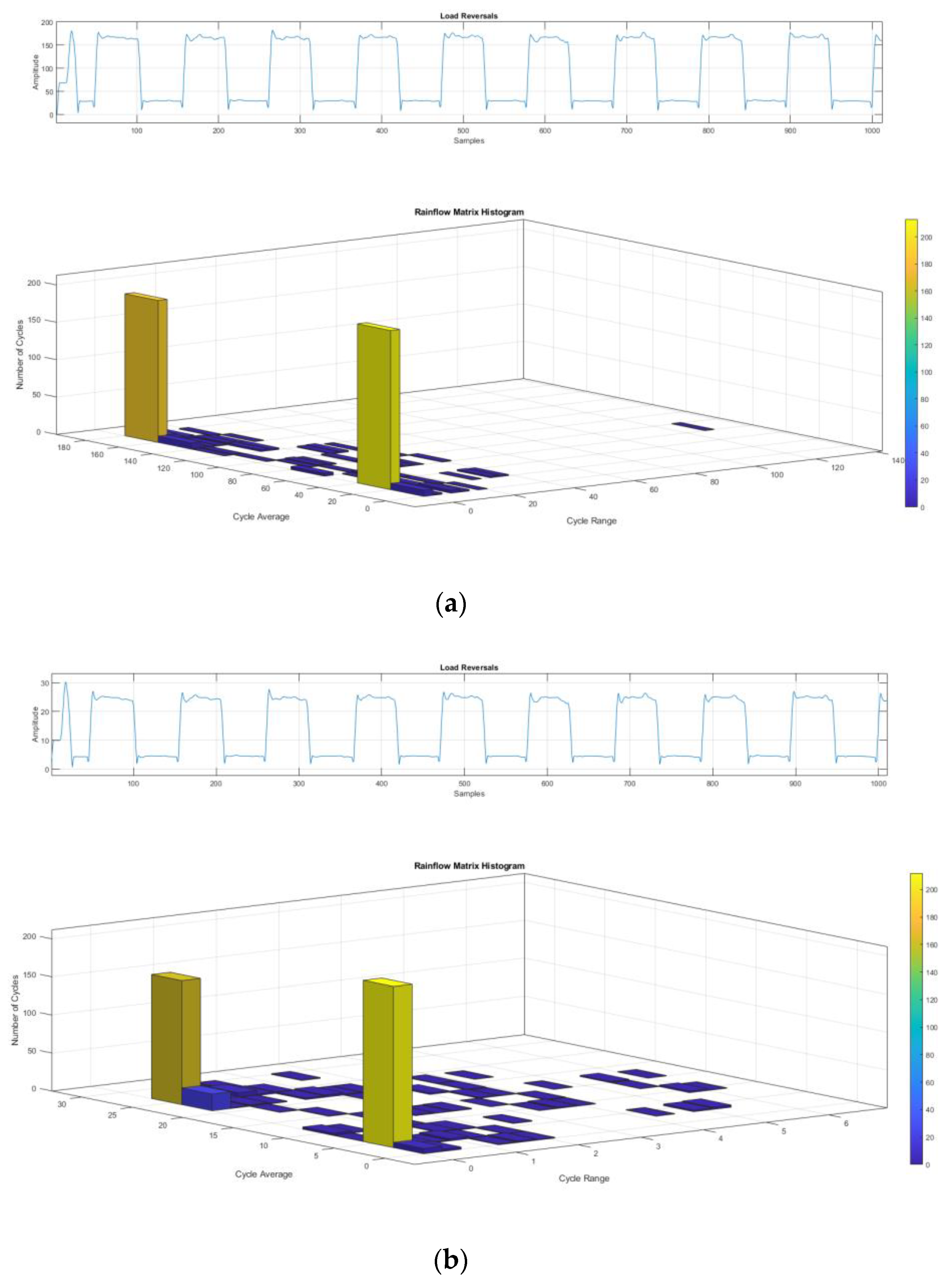
The optimized prosthesis was firstly validated considering its static strength by FE analysis, assuming that the maximum stress of the prosthesis is below the yielding strength of the material. Once the results from the static simulation were obtained, fatigue validation was carried out in the most stressed part of the prosthesis. The load history was reconstructed considering that eighteen single-legged supports are made in 60 s, equivalent to one step every 3.33 s. A total of 788,400 cycles are performed in 10 years. The forces related to the load history were applied to the prosthesis, as depicted in Figure 7. After performing the linear elastic FE simulation to assess the fatigue strength of the prosthesis, stress values were extrapolated from the most stressed point of the prosthesis. The Rainflow method [54] was applied to the stress history coming from FE simulation of the prosthesis with initial and optimized dimensions to obtain simple sinusoidal cycles and compare the results in terms of fatigue strength (Figure 10).
Every sinusoidal cycle is characterized by a specific stress range , a mean stress , a number of working cycles N, and a load ratio R, which, in the vast majority of cases, turned out to be different from . Therefore, to convert all the stress histories into an equivalent one at , the Goodman criterion [55] was applied.
where is the equivalent stress referred to as and is the ultimate tensile stress evaluated from experimental tests. Finally, the cumulative fatigue damage was then evaluated using the Palmgren–Miner criterion [56,57,58,59].
where are the working cycles and are the number of cycles to failure.
3. Results
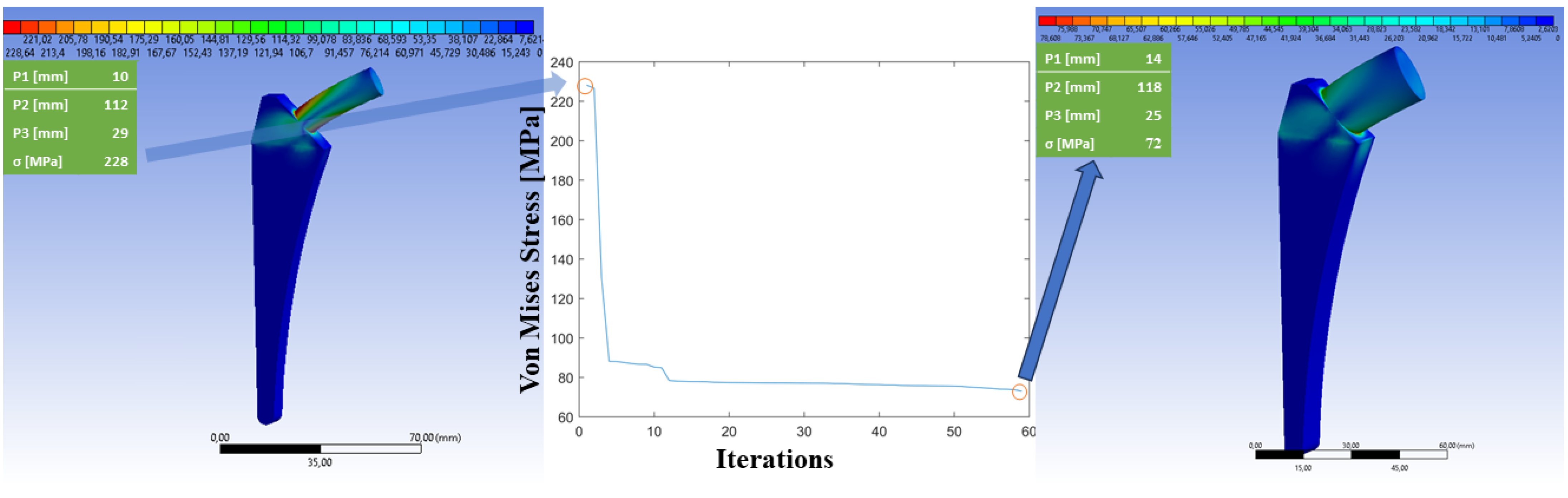
The shape optimization algorithm is a highly efficient tool for finding the best solution to design a customized prosthesis. In each iteration, it calculates 100 different solutions within the designated domain. The algorithm then selects the solution that minimizes von Mises stress, using this as the reference point for the next iteration. Over time, the algorithm goes through thousands of iterations, each time refining the solution and making it more accurate and precise. In total, the algorithm calculates 100,000 solutions, of which only the 60 most characteristics are reported in the results (Figure 11), starting from the combination that generated the highest von Mises stress until the result that minimizes the same is achieved (Figure 11, central graph). This allows researchers to identify trends and patterns quickly and easily and to gain a better understanding of the problem they are trying to solve.
The optimization process resulted in changes to the prosthesis’s mass and dimensions. During the initial phase of parameter adjustment, it was observed that the prosthesis increased in thickness, length, and neck strength compared to the original design while remaining within the manufacturer’s specified range (Table 6).
Table 7 presents a comparison of the sizes between the initial prosthesis and the optimized version in terms of fatigue resistance.
Table 8 highlights the prosthesis’s dimensional changes, focusing on the volume. It also displays the changes in mass and the difference in the von Mises stress calculated for the system. The results showed a significant change in the characteristics of the prosthesis. The volume and mass of the prosthesis increased by approximately 20%, which may have implications for the overall weight of the device. On the other hand, the maximum von Mises stress decreased by 39%. Von Mises stress is a measure of the stress on a material that takes into account both the magnitude and direction of the stress and is commonly used to assess the mechanical behavior of materials. The decrease in von Mises stress suggests that the prosthesis may be better able to withstand external loads and deformations, which could result in improved performance and a longer lifespan of the device. It is important to note that these results are only a first indication of design; indeed, fatigue testing is necessary to fully understand the impact of these changes on the prosthesis. The results may also vary depending on the specific design, materials, and manufacturing process used in prosthesis production. Nonetheless, these results represent an important step forward in improving the design and performance of prosthetic devices.
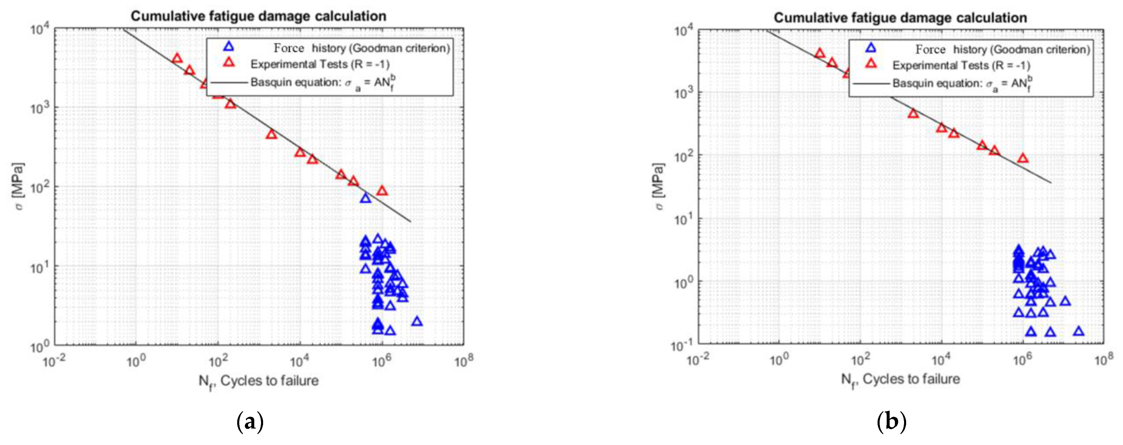
The results of the fatigue damage calculation for the two prosthesis models, the subject-conforming model and the optimized model, are shown in Figure 12. By analyzing the stress history with the Goodman criterion, it is clear that for the traditional prosthesis model, using the Palmgren–Miner criterion, there is 43% damage after a 10-year cycle and 85% damage after a 20-year cycle. However, the optimized prosthesis model was designed for infinite life, and, as a result, no damage was observed.
These results highlight the benefits of using a subject-specific, optimized design for prosthetic devices, as it can lead to an increase of approximately 20% in both mass and volume compared to the initial design. However, this increase in mass and volume contributes to a substantial improvement of approximately 39% in the von Mises stress experienced by the prosthesis. This underscores the significance of optimizing the design based on subject-specific parameters, considering trade-offs in mass and volume for a considerable enhancement in stress distribution. The optimized prosthesis design aims to mitigate stress concentrations, thereby reducing the likelihood of damage and prolonging the device’s lifespan. It is important to note that these results are based on simulations and assumptions made in the analysis. Further testing and validation are necessary to comprehensively understand the performance of the optimized prosthesis model. Nevertheless, these findings present a promising outlook for the potential of optimized prosthesis designs to significantly enhance the quality of life for patients reliant on prosthetic devices, providing a more functional and cost-effective solution.
4. Discussion
The optimization process described in the preceding section exemplifies the application of advanced computational techniques to enhance prosthetic device design. The utilization of these techniques holds the promise of delivering more efficient and effective solutions tailored to the unique needs of each patient. Subject-specific optimization, in particular, emerges as a pivotal approach, as it takes into account an individual’s distinct anatomy and requirements.
One of the critical advantages of optimized prosthetic designs is the improvement of the prosthesis’s alignment with the human joint, ultimately ensuring an extended lifespan for the prosthetic device. This approach promotes a more precise and enduring integration of the prosthesis with the patient’s anatomy.
This, in turn, leads to a substantial improvement in the patient’s mobility and, consequently, their overall quality of life. Additionally, optimized designs have the potential to mitigate complications and discomfort associated with ill-fitting prostheses, including issues such as skin irritation and pressure sores.
Beyond the immediate advantages to patient well-being, optimized prosthetic designs also hold the promise of reducing the overall economic burden of prosthetic devices. The integration of computational techniques into the design process streamlines the iterations required to reach a functional and efficient design, thereby significantly decreasing production costs and timelines. Moreover, by enhancing the durability and longevity of prosthetic devices, optimized designs can diminish the need for frequent replacements and maintenance, thus leading to cost savings for both patients and healthcare systems.
Nonetheless, it is essential to acknowledge the limitations and challenges associated with the adoption of optimized prosthetic designs. Primary among these challenges is the necessity for accurate and reliable data to inform the optimization process. These data encompass information on the patient’s anatomy, movement patterns, and other factors that influence the performance and comfort of the prosthesis. Moreover, the application of advanced computational techniques requires specialized knowledge and expertise, which may only be accessible in select healthcare settings. Another limitation is the requirement for supplementary testing and validation to confirm the safety and effectiveness of optimized prosthetic designs. While computational simulations provide valuable insights into device behavior, physical testing remains pivotal to ensuring the design’s safety and efficacy. This includes mechanical testing, fatigue testing, and various other forms of evaluation.
In conclusion, the implementation of optimized prosthetic designs represents a promising avenue for enhancing the functionality of prosthetic devices. This approach improves the integration between the prosthesis and the human body, creating a device that fits more seamlessly with the joint and ensures the appropriate durability to extend the prosthetic’s lifespan, thereby reducing the need for surgical interventions while simultaneously diminishing the overall cost of care. As computational techniques continue to advance and more comprehensive datasets become available, the integration of optimized designs is expected to proliferate within the field of prosthetics. Nonetheless, it is imperative that researchers, healthcare professionals, and designers remain attuned to the aforementioned challenges and limitations, actively working to address them as they arise to ensure the safe and effective implementation of optimized prosthetic solutions.
This revised discussion section (Section 4) provides a more in-depth and academic approach, addressing the key points while offering a nuanced perspective on the subject of optimized prosthetic designs.
5. Conclusions
During this research, a multifaceted approach to the design of custom hip replacements was employed, incorporating state-of-the-art deep learning algorithms in conjunction with traditional biomechanical techniques. The objective was to establish a benchmark in hip prosthesis design and to streamline the process for assessing the stresses acting upon the hip joint during the gait cycle and calculating the resultant stresses on the prosthesis.
The algorithm utilized OpenPose to detect the subject’s pose with a remarkable degree of accuracy, enabling the evaluation of the forces acting on the hip joint and the specific gait parameters throughout the gait cycle. The parametric human model, when combined with the multibody model and OpenPose, has facilitated a comprehensive analysis of the gait cycle while reducing evaluation times, resulting in a more efficient and precise assessment.
The unique shape optimization algorithm has led to the development of a prosthesis better equipped to withstand the loads it will encounter, resulting in an up to a 40% reduction in von Mises stress during static analysis. By testing the prosthetic device on a loading cycle representative of normal gait, the optimized prosthesis was designed for an indefinite lifespan, demonstrating stress values consistently below the material’s yield strength even under the most adverse conditions evaluated by the algorithm. It is important to point out that clinical considerations and the patient’s specific necessities must be taken into account to define the correct lifespan of the prosthesis.
In contrast, traditional prostheses are typically expected to last only 10 to 20 years and often incur significant damage.
The optimized prosthesis eliminates the need for frequent medical supervision and replacements. In the future, the algorithm will be further refined for dynamic loads and to address the challenges posed by sudden load variations.
The use of AISI 316 L material was confirmed to be suitable for the manufacturing of these prostheses, as it can withstand stress levels well below its yield strength and fatigue limit. This novel approach represents a significant leap forward in the field of hip replacement design and establishes a new industry standard.
Author Contributions
Conceptualization, D.M.; methodology, D.M.; software, D.M.; validation, D.M.; formal analysis, D.M.; investigation, D.M.; resources, D.M.; data curation, D.M., D.D. and D.S.; writing—original draft preparation, D.M., D.D. and D.S.; writing—review and editing, D.M., D.D. and D.S.; visualization, D.M., D.D. and D.S.; supervision, D.M., D.D. and D.S.; project administration, D.M. All authors have read and agreed to the published version of the manuscript.
Funding
This research received no external funding. The author declares that they have no known competing financial interests or personal relationships that could have appeared to influence the work reported in this paper.
Informed Consent Statement
Informed consent was obtained from all subjects involved in the study.
Data Availability Statement
The data presented in this study are available on request from the corresponding author.
Conflicts of Interest
The author declares no conflict of interest.
References
- Franceschini, M.; Sandiford, N.A.; Cerbone, V.; de Araujo, L.C.T.; Kendoff, D. Defensive Antibacterial Coating in Revision Total Hip Arthroplasty: New Concept and Early Experience. HIP Int. 2020, 30, 7–11. [Google Scholar] [CrossRef] [PubMed]
- Torres-Campos, A.; Albareda Albareda, J.; Seral García, B.; Blanco Rubio, N.; Gómez Vallejo, J.; Ezquerra Herrando, L. Burch-Schneider Ring Associated with Morselized Bone Allografts, Survival and Clinical Outcomes after Acetabular Revision Surgery. Rev. Esp. Cir. Ortop. Traumatol. 2018, 62, 428–435. [Google Scholar] [CrossRef]
- Trieu, J.; Gould, D.J.; Schilling, C.; Spelman, T.; Dowsey, M.M.; Choong, P.F. Patient-Reported Outcomes Following Total Knee Replacement in Patients <65 Years of Age—A Systematic Review and Meta-Analysis. J. Clin. Med. 2020, 9, 3150. [Google Scholar] [CrossRef]
- Deere, K.; Whitehouse, M.R.; Kunutsor, S.K.; Sayers, A.; Mason, J.; Blom, A.W. How Long Do Revised and Multiply Revised Hip Replacements Last? A Retrospective Observational Study of the National Joint Registry. Lancet Rheumatol. 2022, 4, e468–e479. [Google Scholar] [CrossRef] [PubMed]
- Cucinotta, F.; Guglielmino, E.; Longo, G.; Risitano, G.; Santonocito, D.; Sfravara, F. Topology Optimization Additive Manufacturing-Oriented for a Biomedical Application. In Lecture Notes in Mechanical Engineering; Springer: Cham, Switzerland, 2019; pp. 184–193. [Google Scholar] [CrossRef]
- Scappaticci, L.; Risitano, G.; Santonocito, D.; D’Andrea, D.; Milone, D. An Approach to the Definition of the Aerodynamic Comfort of Motorcycle Helmets. Vehicles 2021, 3, 33. [Google Scholar] [CrossRef]
- Fellah, M.; Labaïz, M.; Assala, O.; Dekhil, L.; Zerniz, N.; Iost, A. Tribological Behavior of Biomaterial for Total Hip Prosthesis. Mater. Tech. 2014, 102, 601. [Google Scholar] [CrossRef]
- Banchet, V.; Fridrici, V.; Abry, J.C.; Kapsa, P. Wear and Friction Characterization of Materials for Hip Prosthesis. Wear 2007, 263, 1066–1071. [Google Scholar] [CrossRef]
- Kourra, N.; Warnett, J.M.; Attridge, A.; Dibling, G.; McLoughlin, J.; Muirhead-Allwood, S.; King, R.; Williams, M.A. Computed Tomography Metrological Examination of Additive Manufactured Acetabular Hip Prosthesis Cups. Addit. Manuf. 2018, 22, 146–152. [Google Scholar] [CrossRef]
- Murr, L.E. Additive Manufacturing of Biomedical Devices: An Overview. Mater. Technol. 2018, 33, 57–70. [Google Scholar] [CrossRef]
- Cortis, G.; Mileti, I.; Nalli, F.; Palermo, E.; Cortese, L. Additive Manufacturing Structural Redesign of Hip Prostheses for Stress-Shielding Reduction and Improved Functionality and Safety. Mech. Mater. 2022, 165, 104173. [Google Scholar] [CrossRef]
- Milone, D.; Fiorillo, L.; Alberti, F.; Cervino, G.; Filardi, V.; Pistone, A.; Cicciù, M.; Risitano, G. Stress Distribution and Failure Analysis Comparison between Zirconia and Titanium Dental Implants. Procedia Struct. Integr. 2022, 41, 680–691. [Google Scholar] [CrossRef]
- Chethan, K.N.; Guldeniz, O.; Shyamasunder, B.N.; Mohammad, Z.; Satish, S. Wear Estimation of Trapezoidal and Circular Shaped Hip Implants along with Varying Taper Trunnion Radiuses Using Finite Element Method. Comput. Methods Programs Biomed. 2020, 196, 105597. [Google Scholar] [CrossRef] [PubMed]
- Villamor, E.; Monserrat, C.; Del Río, L.; Romero-Martín, J.A.; Rupérez, M.J. Prediction of Osteoporotic Hip Fracture in Postmenopausal Women through Patient-Specific FE Analyses and Machine Learning. Comput. Methods Programs Biomed. 2020, 193, 105484. [Google Scholar] [CrossRef] [PubMed]
- Huston, R.L. Multibody Dynamics Since 1990. Appl. Mech. Rev. 1996, 49, S35–S40. [Google Scholar] [CrossRef]
- Müller, A. Generic Mobility of Rigid Body Mechanisms. Mech. Mach. Theory 2009, 44, 1240–1255. [Google Scholar] [CrossRef]
- D’Andrea, D.; Milone, D.; Nicita, F.; Risitano, G.; Santonocito, D. Qualitative and Quantitative Evaluation of Different Types of Orthodontic Brackets and Archwires by Optical Microscopy and X-Ray Fluorescence Spectroscopy. Prosthesis 2021, 3, 342–360. [Google Scholar] [CrossRef]
- Milone, D.; Nicita, F.; Cervino, G.; Santonocito, D.; Risitano, G. Finite Element Analysis of OT Bridge Fixed Prosthesis System. Procedia Struct. Integr. 2021, 33, 734–747. [Google Scholar] [CrossRef]
- May, B.; Saha, S.; Saltzman, M. A Three-Dimensional Mathematical Model of Temporomandibular Joint Loading. Clin. Biomech. 2001, 16, 489–495. [Google Scholar] [CrossRef]
- Tamer, A.; Zanoni, A.; Cocco, A.; Masarati, P. A Numerical Study of Vibration-Induced Instrument Reading Capability Degradation in Helicopter Pilots. CEAS Aeronaut. J. 2021, 12, 427–440. [Google Scholar] [CrossRef]
- Ackland, D.C.; Moskaljuk, A.; Hart, C.; Vee Sin Lee, P.; Dimitroulis, G. Prosthesis Loading after Temporomandibular Joint Replacement Surgery: A Musculoskeletal Modeling Study. J. Biomech. Eng. 2015, 137, 041001. [Google Scholar] [CrossRef]
- Gröning, F.; Jones, M.E.H.; Curtis, N.; Herrel, A.; O’Higgins, P.; Evans, S.E.; Fagan, M.J. The Importance of Accurate Muscle Modelling for Biomechanical Analyses: A Case Study with a Lizard Skull. J. R. Soc. Interface 2013, 10, 20130216. [Google Scholar] [CrossRef] [PubMed]
- Langenbach, G.E.J.; Hannam, A.G. The Role of Passive Muscle Tensions in a Three-Dimensional Dynamic Model of the Human Jaw. Arch. Oral Biol. 1999, 44, 557–573. [Google Scholar] [CrossRef]
- Shi, J.; Curtis, N.; Fitton, L.C.; O’Higgins, P.; Fagan, M.J. Developing a Musculoskeletal Model of the Primate Skull: Predicting Muscle Activations, Bite Force, and Joint Reaction Forces Using Multibody Dynamics Analysis and Advanced Optimisation Methods. J. Theor. Biol. 2012, 310, 21–30. [Google Scholar] [CrossRef]
- Cheng, H.; Obergefell, L.; Rizer, A. Generator of Body Data (GEBOD), Manual; Defense Technical Information Center: Fort Belvoir, VA, USA, 1994. [Google Scholar]
- Cameron, P.W.; Soltero, N.C.; Byers, J. Effects of a 60 Minute on Ice Game Simulation on the Balance Error Scoring System. Int. J. Exerc. Sci. 2018, 11, 462. [Google Scholar] [PubMed]
- Chung, H.-J. Optimization Based Dynamic Human Motion Prediction with Modular Exoskeleton Robots as Interactive Forces: The Case of Weight Lifting Motion. In Collaborative and Humanoid Robots [Working Title]; IntechOpen: London, UK, 2021. [Google Scholar]
- Uhlrich, S.D.; Falisse, A.; Kidziński, Ł.; Muccini, J.; Ko, M.; Chaudhari, A.S.; Hicks, J.L.; Delp, S.L.; Uhlrich, S. OpenCap: 3D Human Movement Dynamics from Smartphone Videos. bioRxiv 2022. bioRxiv:2022.07.07.499061. [Google Scholar] [CrossRef]
- D’Andrea, D.; Cucinotta, F.; Farroni, F.; Risitano, G.; Santonocito, D.; Scappaticci, L. Development of Machine Learning Algorithms for the Determination of the Centre of Mass. Symmetry 2021, 13, 401. [Google Scholar] [CrossRef]
- Winter, D.A. Biomechanics and Motor Control of Human Movement, 4th ed.; John Wiley & Sons, Inc.: Hoboken, NJ, USA, 2009; pp. 1–370. [Google Scholar] [CrossRef]
- Whittle, M.W. Gait Analysis; Elsevier: Amsterdam, The Netherlands, 2007. [Google Scholar] [CrossRef]
- Ramakrishna, V.; Munoz, D.; Hebert, M.; Andrew Bagnell, J.; Sheikh, Y. Pose Machines: Articulated Pose Estimation via Inference Machines. In Proceedings of the Lecture Notes in Computer Science (Including Subseries Lecture Notes in Artificial Intelligence and Lecture Notes in Bioinformatics), 8690 LNCS, Zurich, Switzerland, 6–12 September 2014; pp. 33–47. [Google Scholar]
- Bulat, A.; Tzimiropoulos, G. Human Pose Estimation via Convolutional Part Heatmap Regression. In Proceedings of the Lecture Notes in Computer Science (Including Subseries Lecture Notes in Artificial Intelligence and Lecture Notes in Bioinformatics), 9911 LNCS, Amsterdam, The Netherlands, 11–14 October 2016; pp. 717–732. [Google Scholar] [CrossRef]
- Ramanan, D.; Forsyth, D.A.; Zisserman, A. Strike a Pose: Tracking People by Finding Stylized Poses. In Proceedings of the 2005 IEEE Computer Society Conference on Computer Vision and Pattern Recognition, CVPR, San Diego, CA, USA, 20–25 June 2005; Volume I; pp. 271–278. [Google Scholar] [CrossRef]
- Johnson, S.; Everingham, M. Clustered Pose and Nonlinear Appearance Models for Human Pose Estimation. In Proceedings of the British Machine Vision Conference, BMVC, Aberystwyth, UK, 31 August–3 September 2010. [Google Scholar] [CrossRef]
- Yang, Y.; Ramanan, D. Articulated Human Detection with Flexible Mixtures of Parts. IEEE Trans. Pattern Anal. Mach. Intell. 2013, 35, 2878–2890. [Google Scholar] [CrossRef]
- Andriluka, M.; Roth, S.; Schiele, B. Pictorial Structures Revisited: People Detection and Articulated Pose Estimation. In Proceedings of the 2009 IEEE Conference on Computer Vision and Pattern Recognition, Miami, FL, USA, 20–25 June 2009; pp. 1014–1021. [Google Scholar] [CrossRef]
- Wei, S.E.; Ramakrishna, V.; Kanade, T.; Sheikh, Y. Convolutional Pose Machines. In Proceedings of the IEEE Computer Society Conference on Computer Vision and Pattern Recognition, Las Vegas, NV, USA, 27–30 June 2016; pp. 4724–4732. [Google Scholar] [CrossRef]
- Simon, T.; Joo, H.; Matthews, I.; Sheikh, Y. Hand Keypoint Detection in Single Images Using Multiview Bootstrapping. In Proceedings of the 30th IEEE Conference on Computer Vision and Pattern Recognition, CVPR, Honolulu, HI, USA, 21–26 July 2017; pp. 4645–4653. [Google Scholar] [CrossRef]
- Pfister, T.; Charles, J.; Zisserman, A. Flowing ConvNets for Human Pose Estimation in Videos. In Proceedings of the IEEE International Conference on Computer Vision, Santiago, Chile, 7–13 December 2015. [Google Scholar]
- Insafutdinov, E.; Pishchulin, L.; Andres, B.; Andriluka, M.; Schiele, B. DeeperCut: A Deeper, Stronger, and Faster Multi-Person Pose Estimation Model. In Proceedings of the Lecture Notes in Computer Science (Including Subseries Lecture Notes in Artificial Intelligence and Lecture Notes in Bioinformatics), 9910 LNCS, Amsterdam, The Netherlands, 11–14 October 2016; pp. 34–50. [Google Scholar] [CrossRef]
- Pishchulin, L.; Insafutdinov, E.; Tang, S.; Andres, B.; Andriluka, M.; Gehler, P.V.; Schiele, B. DeepCut: Joint Subset Partition and Labeling for Multi Person Pose Estimation. In Proceedings of the IEEE Conference on Computer Vision and Pattern Recognition, Las Vegas, VA, USA, 27–30 June 2016; pp. 4929–4937. [Google Scholar]
- Cao, Z.; Hidalgo, G.; Simon, T.; Wei, S.E.; Sheikh, Y. OpenPose: Realtime Multi-Person 2D Pose Estimation Using Part Affinity Fields. IEEE Trans. Pattern Anal. Mach. Intell. 2018, 43, 172–186. [Google Scholar] [CrossRef]
- Cao, Z.; Simon, T.; Wei, S.-E.; Sheikh, Y. Realtime Multi-Person 2D Pose Estimation Using Part Affinity Fields. In Proceedings of the IEEE Conference on Computer Vision and Pattern Recognition, Honolulu, HI, USA, 21–26 July 2017; pp. 7291–7299. [Google Scholar]
- Martinez, G.H.; Raaj, Y.; Idrees, H.; Xiang, D.; Joo, H.; Simon, T.; Sheikh, Y. Single-Network Whole-Body Pose Estimation. In Proceedings of the IEEE International Conference on Computer Vision, Seoul, Republic of Korea, 27 October–2 November 2019; pp. 6981–6990. [Google Scholar] [CrossRef]
- Pagnon, D.; Domalain, M.; Reveret, L. Pose2Sim: An End-to-End Workflow for 3D Markerless Sports Kinematics—Part 1: Robustness. Sensors 2021, 21, 6530. [Google Scholar] [CrossRef]
- Viswakumar, A.; Rajagopalan, V.; Ray, T.; Parimi, C. Human Gait Analysis Using OpenPose. In Proceedings of the 2019 Fifth International CONFERENCE on image Information Processing (ICIIP), Shimla, India, 15–17 November 2019; pp. 310–314. [Google Scholar] [CrossRef]
- Young, S.N.; VanWye, W.R.; Wallmann, H.W. Sport Simulation as a Form of Implicit Motor Training in a Geriatric Athlete after Stroke: A Case Report. Physiother. Theory Pract. 2018, 36, 524–532. [Google Scholar] [CrossRef]
- Anthropometric Database—Army Public Health Center. Available online: https://phc.amedd.army.mil/topics/workplacehealth/ergo/Pages/Anthropometric-Database.aspx (accessed on 7 September 2022).
- Milone, D.; Risitano, G.; Pistone, A.; Crisafulli, D.; Alberti, F. A New Approach for the Tribological and Mechanical Characterization of a Hip Prosthesis Trough a Numerical Model Based on Artificial Intelligence Algorithms and Humanoid Multibody Model. Lubricants 2022, 10, 160. [Google Scholar] [CrossRef]
- Walczak, J.; Shahgaldi, F.; Heatley, F. In Vivo Corrosion of 316L Stainless-Steel Hip Implants: Morphology and Elemental Compositions of Corrosion Products. Biomaterials 1998, 19, 229–237. [Google Scholar] [CrossRef] [PubMed]
- Alberti, F.; Foti, P.; Berto, F.; Risitano, G.; D’Andrea, D. Fatigue Life Evaluation of Automotive Mechanical Components by Using Smart Design Algorithm. Fatigue Fract. Eng. Mater. Struct. 2022, 46, 1401–1412. [Google Scholar] [CrossRef]
- Previti, U.; Galvagno, A.; Risitano, G.; Alberti, F. Smart Design: Application of an Automatic New Methodology for the Energy Assessment and Redesign of Hybrid Electric Vehicle Mechanical Components. Vehicles 2022, 4, 586–607. [Google Scholar] [CrossRef]
- Amzallag, C.; Gerey, J.P.; Robert, J.L.; Bahuaud, J. Standardization of the Rainflow Counting Method for Fatigue Analysis. Int. J. Fatigue 1994, 16, 287–293. [Google Scholar] [CrossRef]
- Nicholas, T.; Zuiker, J.R. On the Use of the Goodman Diagram for High Cycle Fatigue Design. Int. J. Fract. 1989, 80, 219–235. [Google Scholar] [CrossRef]
- Kauzlarich, J.J. The Palmgren-Miner Rule Derived. Tribol. Ser. 1989, 14, 175–179. [Google Scholar] [CrossRef]
- Palmgren, A. The Service Life of Ball Bearings (Durability and Service Life of Ball Bearings). 1971. Available online: https://ntrl.ntis.gov/NTRL/dashboard/searchResults/titleDetail/N7119009.xhtml (accessed on 15 August 2023).
- Miner, M.A. Cumulative damage in fatigue. J. Appl. Mech. 1945, 12, A159–A164. [Google Scholar] [CrossRef]
- Goodman, R.E.; Taylor, R.L.; Brekke, T.L. A model for the mechanics of jointed rock. J. Soil Mech. Found. Div. 1968, 94, 637–659. [Google Scholar] [CrossRef]
Figure 1.
Angle measurements from the video frame [48].
Figure 1.
Angle measurements from the video frame [48].

Figure 2.
Bipedal gait cycle.

Figure 3.
Body selection scheme.

Figure 4.
Comparison between keypoints computed using OpenPose and a virtual multibody model pose created in Adams for gait analysis.
Figure 4.
Comparison between keypoints computed using OpenPose and a virtual multibody model pose created in Adams for gait analysis.

Figure 5.
(a) Vertical forces applied to the hip joint during a 60 s gait cycle. (b) Lateral forces applied to the hip joint during a 60 s gait cycle.
Figure 5.
(a) Vertical forces applied to the hip joint during a 60 s gait cycle. (b) Lateral forces applied to the hip joint during a 60 s gait cycle.

Figure 6.
Parameter settings. (a) Three-dimensional model of the prosthesis; (b) shape optimization workflow; (c) changing of the parameter P1 for every iteration step; (d) changing of the second parameter P2 for every iteration step; (e) changing of the third parameter P3 for every iteration step.
Figure 6.
Parameter settings. (a) Three-dimensional model of the prosthesis; (b) shape optimization workflow; (c) changing of the parameter P1 for every iteration step; (d) changing of the second parameter P2 for every iteration step; (e) changing of the third parameter P3 for every iteration step.

Figure 7.
(a) Load schematization; (b) load and constraints of the system.

Figure 8.
Mesh sensitivity: initial mesh (left) and mesh obtained by convergence analysis (right).

Figure 9.
Experimental fatigue test results from AISI 316L.

Figure 10.
(a) Rainflow histogram of the original prosthesis model stress history; (b) Rainflow histogram of the optimized prosthesis model stress history.
Figure 10.
(a) Rainflow histogram of the original prosthesis model stress history; (b) Rainflow histogram of the optimized prosthesis model stress history.

Figure 11.
Simulation iterations for the customized prosthesis design.

Figure 12.
(a) Original prosthesis: stress history referred to as R = −1 through the Goodman criterion; (b) Optimized prosthesis: stress history referred to as R = −1 through the Goodman criterion.
Figure 12.
(a) Original prosthesis: stress history referred to as R = −1 through the Goodman criterion; (b) Optimized prosthesis: stress history referred to as R = −1 through the Goodman criterion.


Table 1.
Camera technical features.
| Camera Technical Features | |
|---|---|
| Resolution | 1080P (30 fps) |
| Pixel | 20 MP |
| Dimensions | 5.9 × 2.5 × 4 cm; 60 g |
Table 2.
Gait parameters.
| Gait Parameters | |
|---|---|
| Step frequencies fP [step/min] | 18 |
| Cycle length lc [m] | 1.4 |
Table 3.
Body dimensions.
| Reference Number | Dimension | Reference Number | Dimension |
|---|---|---|---|
| 0 | Weight | 16 | Hip Breadth, Standing |
| 1 | Standing Height | 17 | Shoulder to Elbow Length |
| 2 | Shoulder Height | 18 | Forearm-Hand Length |
| 3 | Armpit Height | 19 | Biceps Circumference |
| 4 | Waist Height | 20 | Elbow Circumference |
| 5 | Seated Height | 21 | Forearm Circumference |
| 6 | Head Length | 22 | Waist Circumference |
| 7 | Head Breadth | 23 | Knee Height, Seated |
| 8 | Head to Chin Height | 24 | Thigh Circumference |
| 9 | Neck Circumference | 25 | Upper Leg Circumference |
| 10 | Shoulder Breadth | 26 | Knee Circumference |
| 11 | Chest Depth | 27 | Calf Circumference |
| 12 | Chest Breadth | 28 | Ankle Circumference |
| 13 | Waist Depth | 29 | Ankle Height, Outside |
| 14 | Waist Breadth | 30 | Foot Breadth |
| 15 | Buttock Depth | 31 | Foot Length |
Table 4.
Subject characteristics.
| Human Characteristics | |
|---|---|
| Weight | 85 kg |
| Standing Height | 1755 mm |
| Seated Height | 918 mm |
Table 5.
AISI 316L properties.
| Material Properties | |
|---|---|
| Density [kg/mm3] | 7954 |
| Young Modulus [GPa] | 195 |
| Poisson Ratio | 0.25 |
| Bulk Modulus [GPa] | 190 |
| Shear Modulus [GPa] | 78 |
| Yield Strength [MPa] | 250 |
| Tangent Modulus [MPa] | 2091 |
Table 6.
Shape optimization boundary limits.
| Shape Optimization | ||
|---|---|---|
| lowest acceptable measures | highest acceptable measures | |
| P1 [mm] | 10 | 18 |
| P2 [mm] | 110 | 115 |
| P3 [mm] | 25 | 30 |
Table 7.
Shape optimization parameters.
| Shape Optimization | ||
|---|---|---|
| Original Dimensions | Optimized Dimensions | |
| P1 [mm] | 15 | 18.00 |
| P2 [mm] | 111 | 114.78 |
| P3 [mm] | 26 | 25.00 |
Table 8.
Volume and mass variation.
| Shape Optimization | |||
|---|---|---|---|
| Original Dimensions | Optimized Dimensions | Variation | |
| Volume [mm3] | 28,012 | 35,066 | +20% |
| Mass [kg] | 0.22 | 0.28 | +21% |
| Stress [MPa] | 120 | 72 | −39% |
Disclaimer/Publisher’s Note: The statements, opinions and data contained in all publications are solely those of the individual author(s) and contributor(s) and not of MDPI and/or the editor(s). MDPI and/or the editor(s) disclaim responsibility for any injury to people or property resulting from any ideas, methods, instructions or products referred to in the content. |
© 2023 by the authors. Licensee MDPI, Basel, Switzerland. This article is an open access article distributed under the terms and conditions of the Creative Commons Attribution (CC BY) license (https://creativecommons.org/licenses/by/4.0/).
Share and Cite
MDPI and ACS Style
Milone, D.; D’Andrea, D.; Santonocito, D. Smart Design of Hip Replacement Prostheses Using Additive Manufacturing and Machine Learning Techniques. Prosthesis 2024, 6, 24-40. https://0-doi-org.brum.beds.ac.uk/10.3390/prosthesis6010002
AMA Style
Milone D, D’Andrea D, Santonocito D. Smart Design of Hip Replacement Prostheses Using Additive Manufacturing and Machine Learning Techniques. Prosthesis. 2024; 6(1):24-40. https://0-doi-org.brum.beds.ac.uk/10.3390/prosthesis6010002
Chicago/Turabian StyleMilone, Dario, Danilo D’Andrea, and Dario Santonocito. 2024. "Smart Design of Hip Replacement Prostheses Using Additive Manufacturing and Machine Learning Techniques" Prosthesis 6, no. 1: 24-40. https://0-doi-org.brum.beds.ac.uk/10.3390/prosthesis6010002