Studies on the Modification of Commercial Bisphenol-A-Based Epoxy Resin Using Different Multifunctional Epoxy Systems


Abstract
:1. Introduction
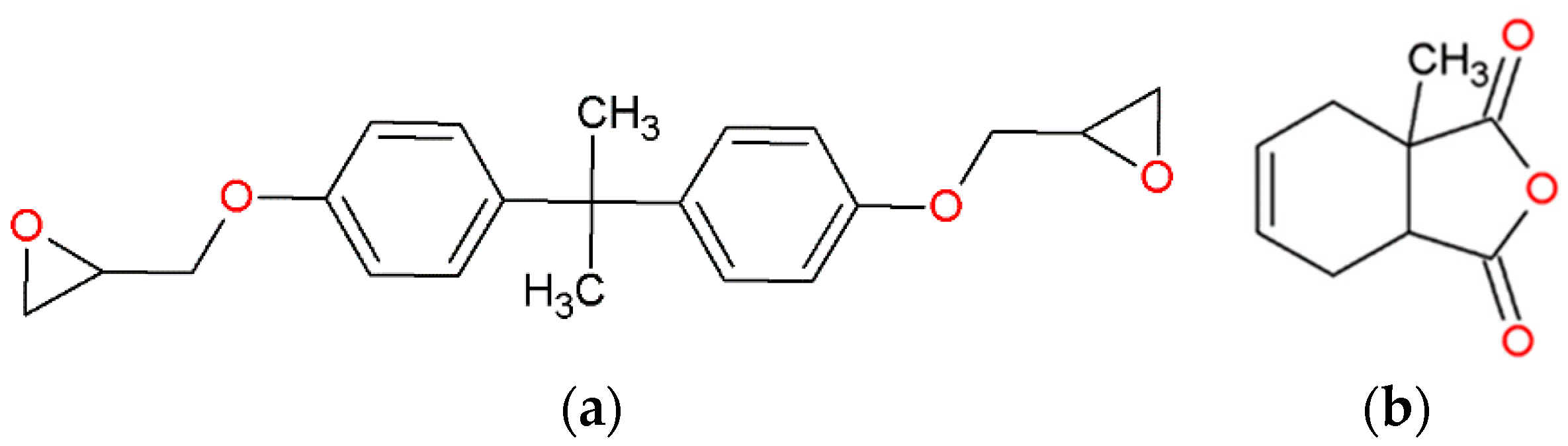
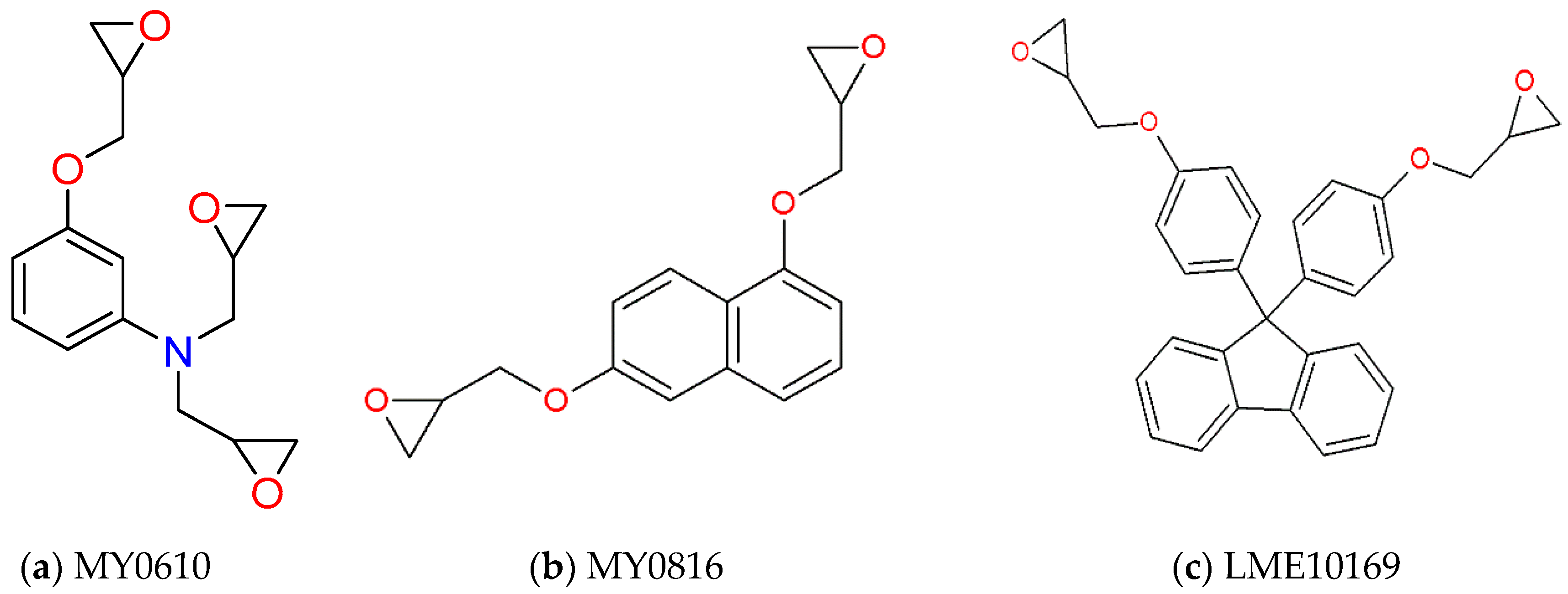
2. Materials
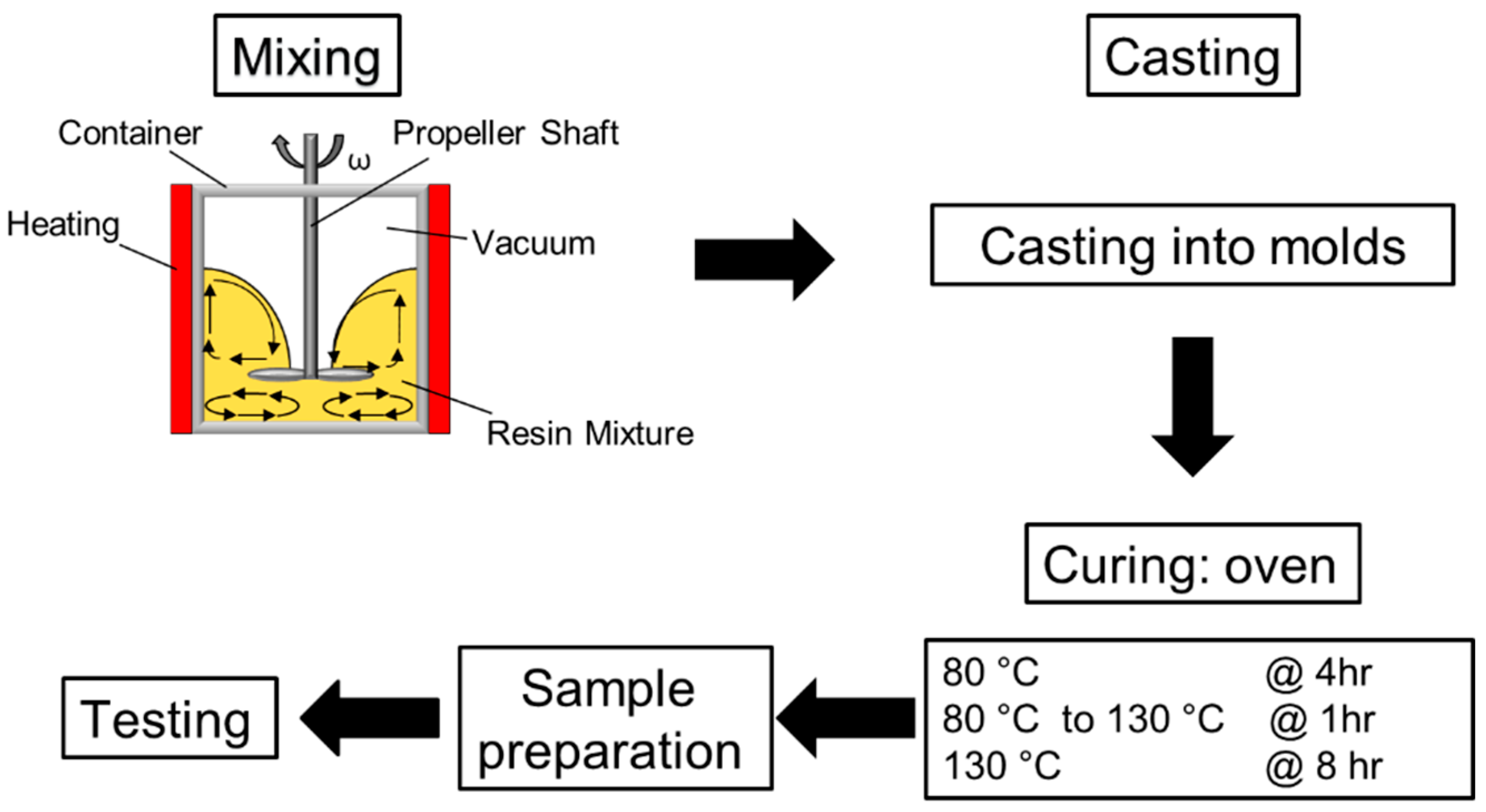
3. Experimental Methods
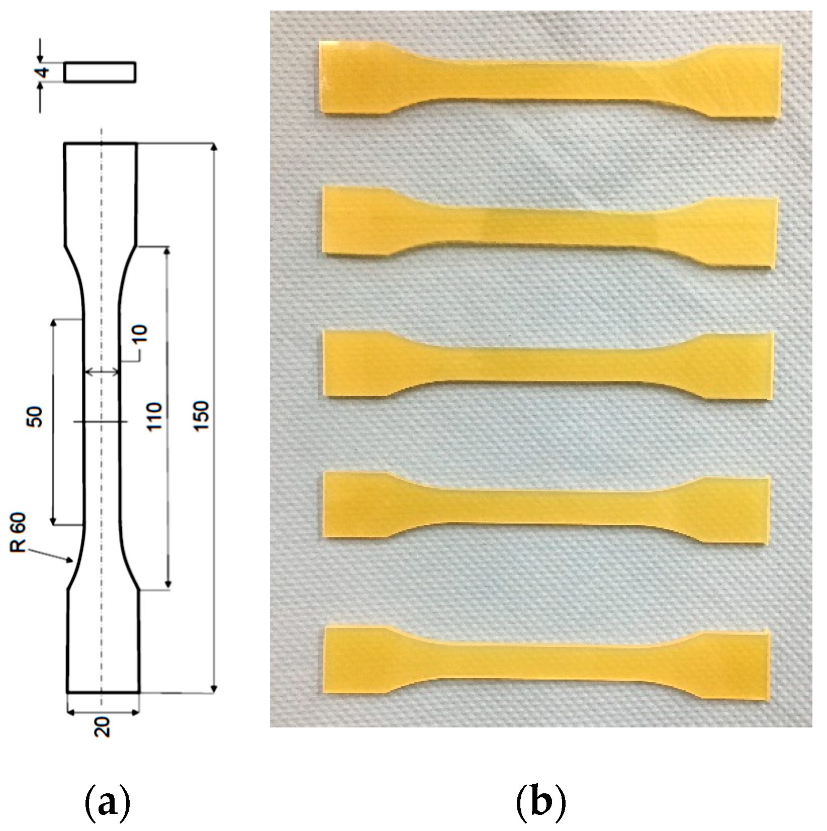
3.1. Tensile Tests
3.2. Differential Scanning Calorimetry (DSC)
3.3. Dynamic Mechanical Thermal Analysis (DMA)
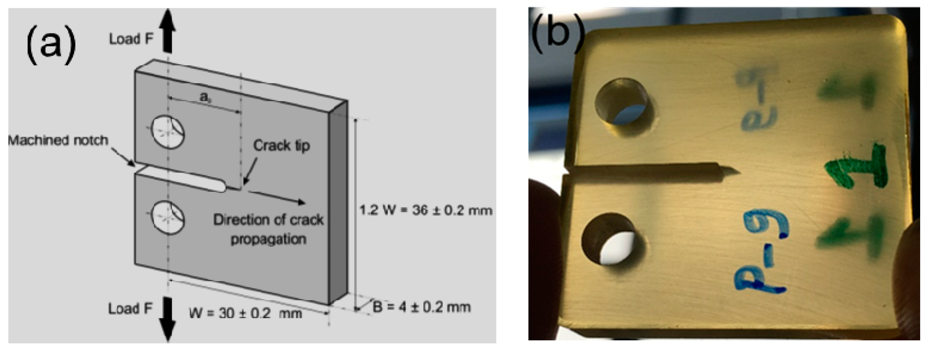
3.4. Fracture Toughness Tests
3.5. Scanning Electron Microscopy
4. Results and Discussion
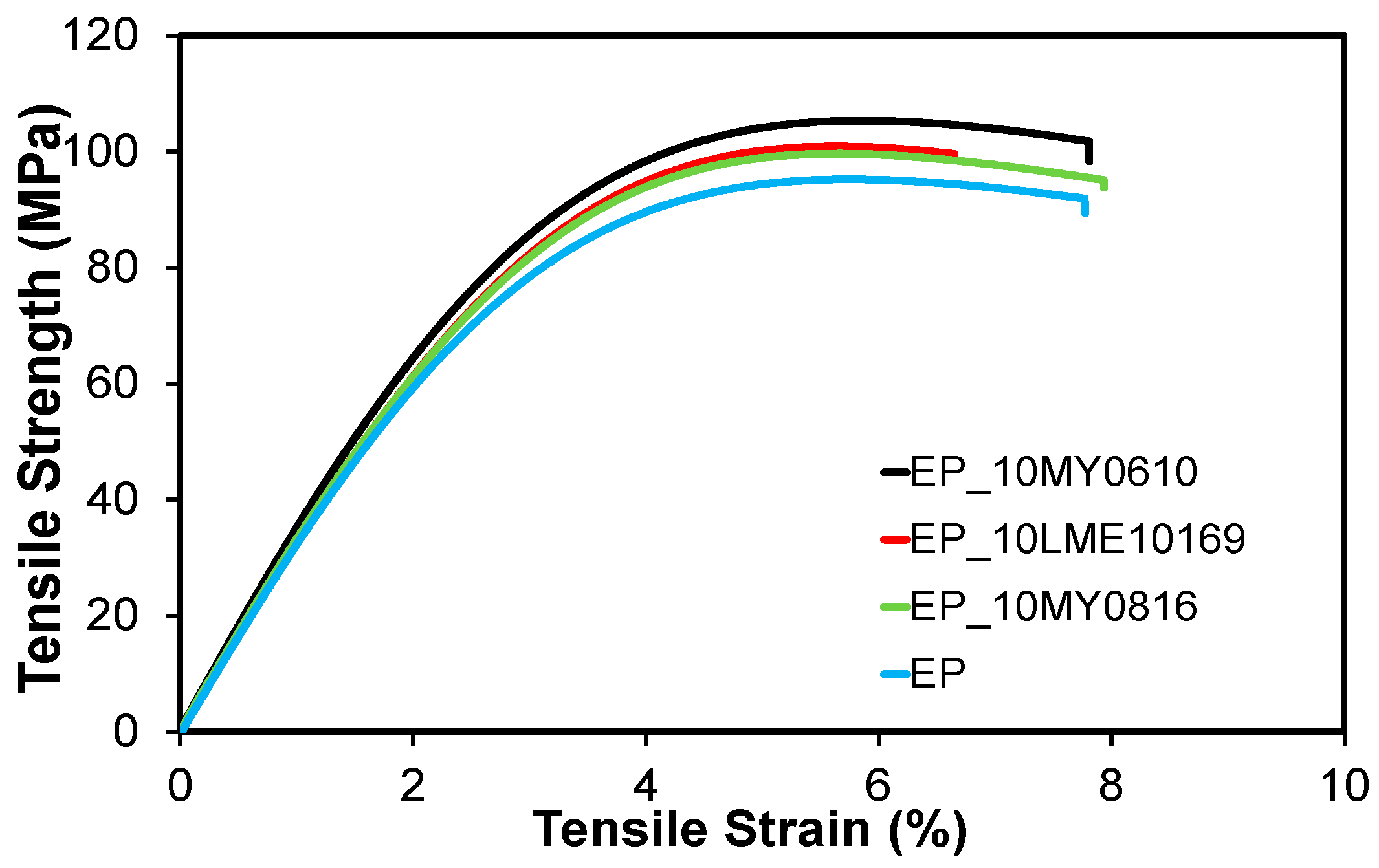
4.1. Tensile and Fracture Properties
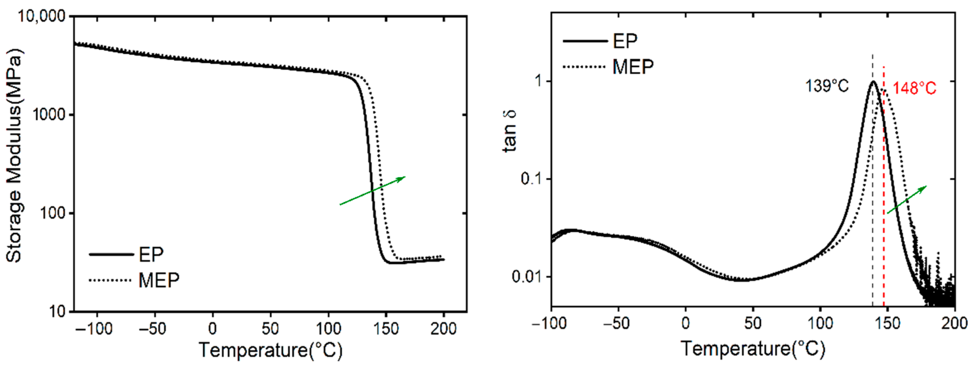
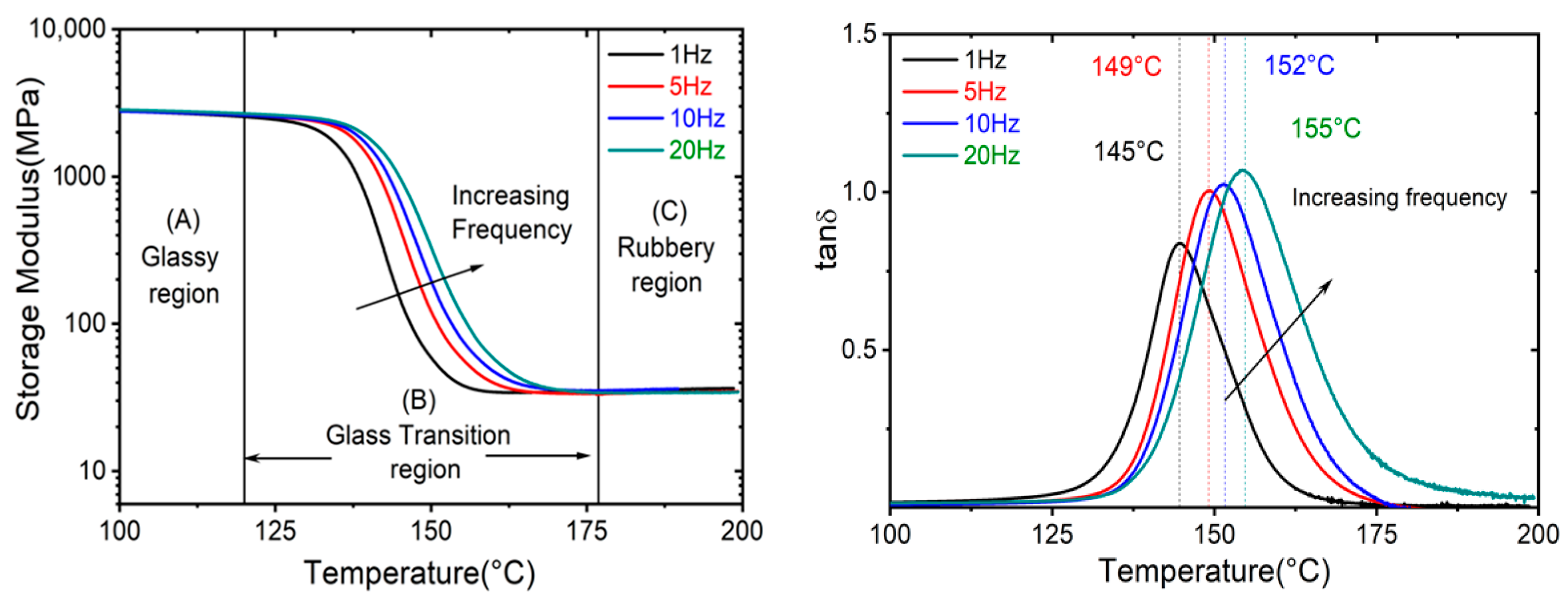
4.2. Thermal and Viscoelastic Properties
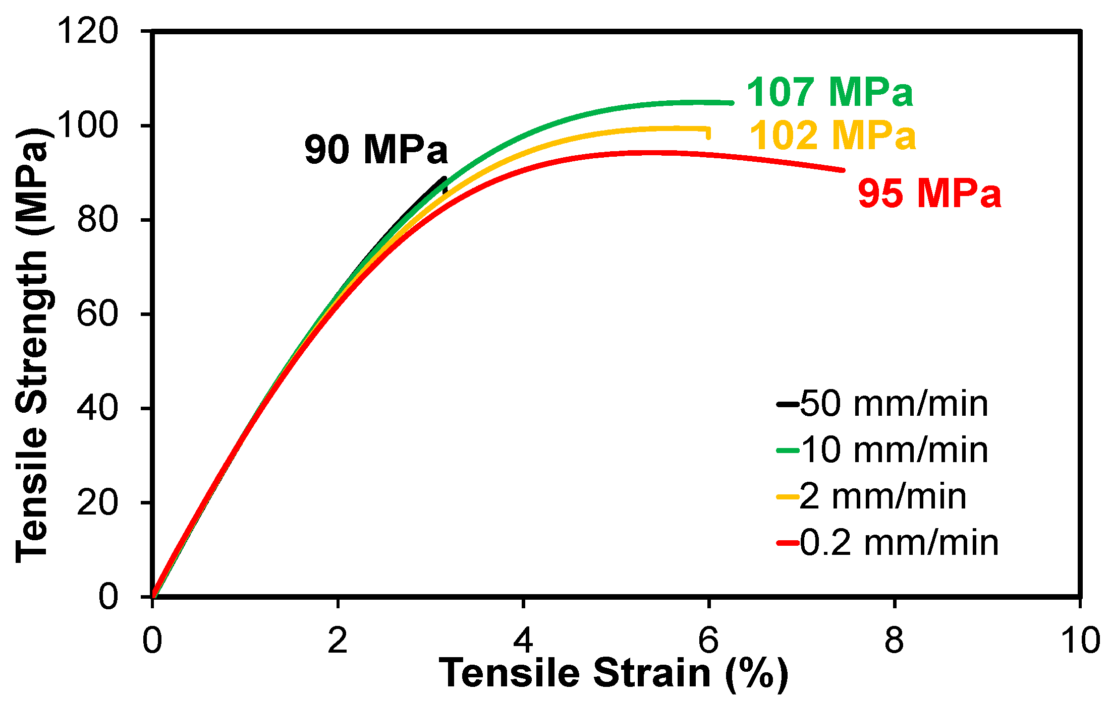
4.3. Effect of Strain Rate on Tensile Properties
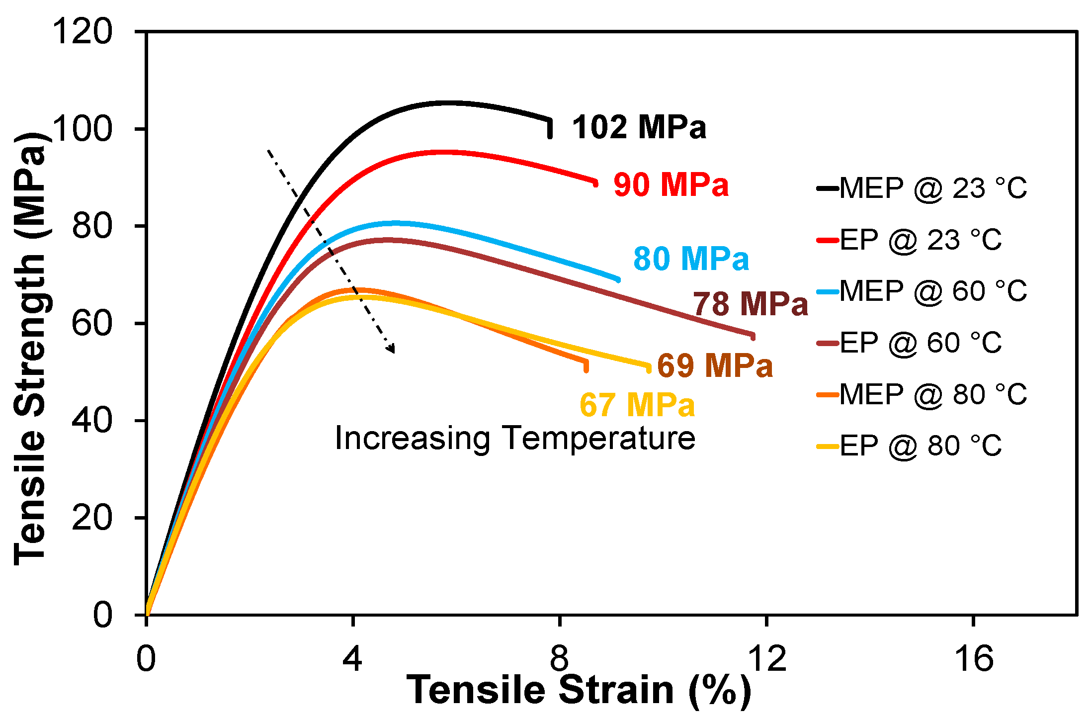
4.4. Effect of Temperature on Tensile Properties
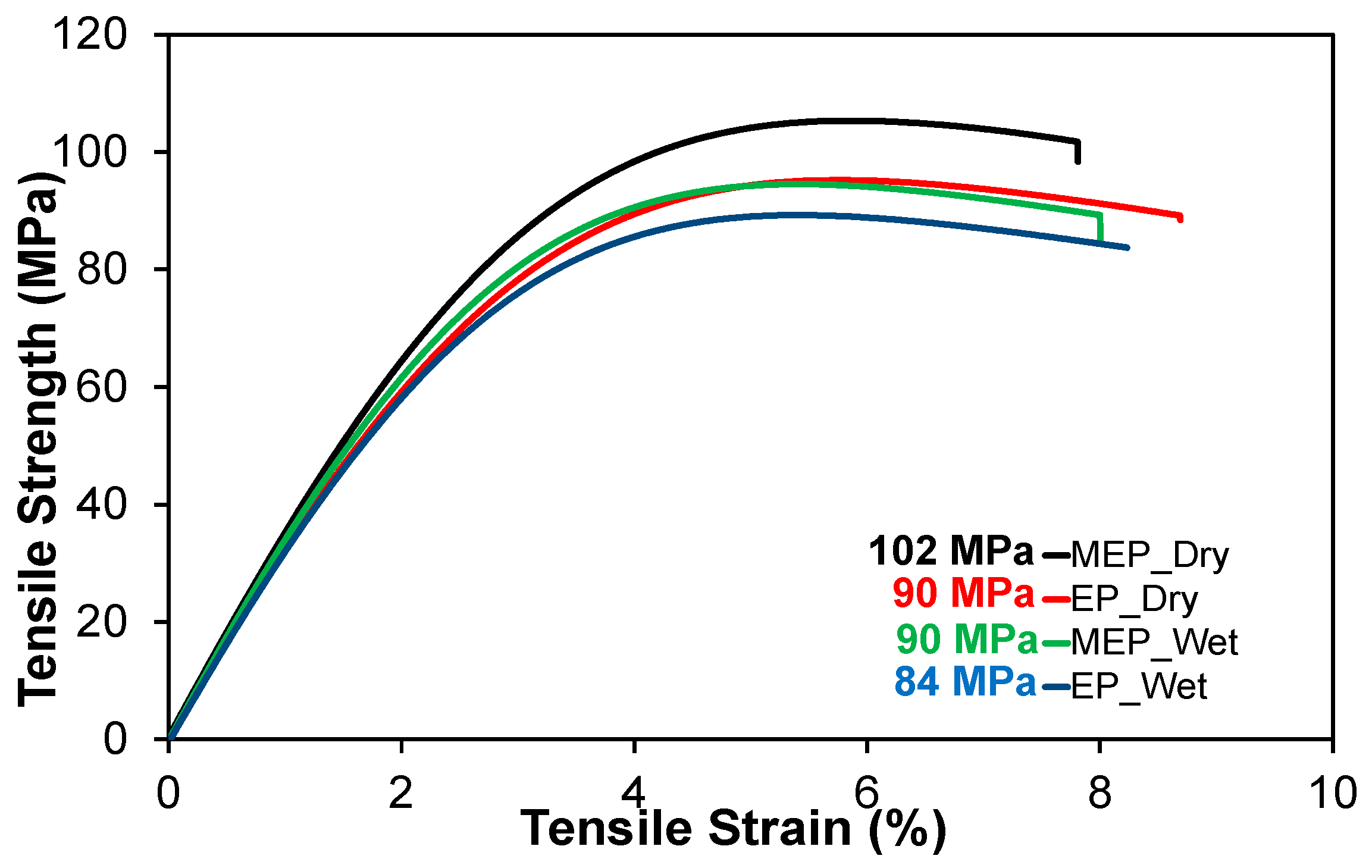
4.5. Effect of Moisture on Tensile Properties
5. Conclusions
Author Contributions
Funding
Institutional Review Board Statement
Informed Consent Statement
Acknowledgments
Conflicts of Interest
References
- Klingler, A.; Bajpai, A.; Wetzel, B. The effect of block copolymer and core-shell rubber hybrid toughening on morphology and fracture of epoxy-based fibre reinforced composites. Eng. Fract. Mech. 2018, 203, 81–101. [Google Scholar] [CrossRef]
- Bajpai, A.; Wetzel, B.; Friedrich, K. High strength epoxy system modified with soft block copolymer and stiff core-shell rubber nanoparticles. Express Polym. Lett. 2020, 14, 384–399. [Google Scholar] [CrossRef]
- Bajpai, A.; Wetzel, B. Effect of different types of block copolymers on morphology, mechanical properties, and fracture mechanisms of bisphenol-F based epoxy system. J. Compos. Sci. 2019, 3, 68. [Google Scholar] [CrossRef] [Green Version]
- Bajpai, A.; Carlotti, S. The Effect of Hybridized Carbon Nanotubes, Silica Nanoparticles, and Core-Shell Rubber on Tensile, Fracture Mechanics and Electrical Properties of Epoxy Nanocomposites. Nanomaterials 2019, 9, 1057. [Google Scholar] [CrossRef] [Green Version]
- Bajpai, A.; Alapati, A.K.; Klingler, A.; Wetzel, B. Tensile properties, fracture mechanics properties and toughening mechanisms of epoxy systems modified with soft block copolymers, rigid TiO2 nanoparticles and their hybrids. J. Compos. Sci. 2018, 2, 72. [Google Scholar] [CrossRef] [Green Version]
- Bajpai, A.; Alapati, K.; Wetzel, B. Toughening and mechanical properties of epoxy modified with block co-polymers and MWCNTs. Procedia Struct. Integr. 2016, 2, 104–111. [Google Scholar] [CrossRef] [Green Version]
- Bajpai, A.; Martin, R.; Faria, H.; Ibarboure, E.; Carlotti, S. Epoxy based hybrid nanocomposites: Fracture mechanisms, tensile properties and electrical properties. Mater. Today Proc. 2021, 34, 210–216. [Google Scholar] [CrossRef]
- Hsieh, T.H.; Kinloch, A.J.; Masania, K.; Taylor, A.C.; Sprenger, S. The mechanisms and mechanics of the toughening of epoxy polymers modified with silica nanoparticles. Polymer 2010, 51, 6284–6294. [Google Scholar] [CrossRef] [Green Version]
- Sprenger, S. Nanosilica-toughened epoxy resins. Polymers 2020, 12, 1777. [Google Scholar] [CrossRef]
- Unnikrishnan, K.P.; Thachil, E.T. Hybrid polymer networks of epoxy resin and substituted phenolic novolacs. Int. J. Polym. Mater. 2006, 55, 563–576. [Google Scholar] [CrossRef]
- Unnikrishnan, K.P.; Thachil, E.T. Studies on the Modification of Commercial Epoxy Resin using Cardanol-Based Phenolic Resins. J. Elastomers Plast. 2008, 40, 271–286. [Google Scholar] [CrossRef]
- Downey, M.A.; Drzal, L.T. Toughening of aromatic epoxy via aliphatic epoxy copolymers. Polymer 2014, 55, 6658–6663. [Google Scholar] [CrossRef]
- Khalina, M.; Beheshty, M.H.; Salimi, A. Preparation and characterization of DGEBA/EPN epoxy blends with improved fracture toughness. Chin. J. Polym. Sci. 2018, 36, 632–640. [Google Scholar] [CrossRef]
- Bellenger, V.; Dhaoui, W.; Verdu, J.; Lacabanne, J.B.C. Internal antiplasticization in diglycidyl ether of bisphenol A diamino diphenyl methane non-stoichiometric epoxy networks. Polym. Eng. Sci. 1990, 30, 321–325. [Google Scholar] [CrossRef]
- Mafi, E.R.; Ebrahimi, M.; Moghbeli, M.R. Effect of matrix crosslink density, varied by stoichiometry and resin molecular weight, on fracture behavior of epoxy resins. J. Polym. Eng. 2009, 29, 293–308. [Google Scholar] [CrossRef]
- Mostovoy, S.; Ripling, E.J. Fracture toughness of an epoxy system. J. Appl. Polym. Sci. 1966, 10, 1351–1371. [Google Scholar] [CrossRef]
- Sika Deutschland GmbH. Biresin® CR144 Product Data Sheet. 2020. Available online: https://industry.sika.com/content/dam/dms/global-industry/m/Biresin-CR144-Anhydrid-New.pdf (accessed on 1 June 2021).
- Huntsman. Technical Data Sheet for Araldite MY 0610 Trifunctional Resin; Huntsman Advance Materials GmbH: Basel, Switzerland, 2015. [Google Scholar]
- Huntsman. Technical Data Sheet for Araldite MY 0816; Huntsman Advance Materials GmbH: Basel, Switzerland, 2015. [Google Scholar]
- Huntsman. Technical Data Sheet for Developmental Resin LME10169; Huntsman Advance Materials GmbH: Basel, Switzerland, 2015. [Google Scholar]
- Huntsman. Advance Material Raising Performance with Building Blocks. 2012. Available online: http://www.huntsman.com/advanced_materials/Media%20Library/global/files/EUR_HL_Components_Raising%20performance%20with%20Building%20blocks.pdf (accessed on 10 April 2021).
- DIN-EN-ISO-527-1. General Principles for the Determination of Tensile Properties; DIN Deutsches Institut für Normung: Berlin, Germany, 1996. [Google Scholar]
- ISO 6721-11:2019 Plastics. Determination of Dynamic Mechanical Properties—Part 11: Glass Transition Temperature; ISO (The International Organization for Standardization): Berlin, Germany, 2019. [Google Scholar]
- TA Instruments. Measurement of Glass Transition Temperatures by Dynamic Mechanical Analysis and Rheology (RH100). Available online: https://www.tainstruments.com/pdf/literature/RH100.pdf (accessed on 3 May 2021).
- Kinloch, A.J.; Young, R.J. Fracture Behaviour of Polymers; Elsevier Applied Science: New York, NY, USA, 1983. [Google Scholar]
- ISO 13586:2000(E). Plastics—Determination of Fracture Toughness (GIc and KIc)—Linear Elastic Fracture Mechanics (LEFM) Approach; ISO (The International Organization for Standardization): Gevena, Switzerland, 2018. [Google Scholar]
- Xiao, K.; Ye, L.; Kwok, Y.S. Effects of pre-cracking methods on fracture behaviour of an Araldite-F epoxy and its rubber-modified systems. J. Mater. Sci. 1998, 33, 2831–2836. [Google Scholar] [CrossRef]
- Yamini, S.; Young, R.J. The mechanical properties of epoxy resins. J. Mater. Sci. 1980, 15, 1814–1822. [Google Scholar] [CrossRef]
- Cook, W.D.; Mayr, A.E.; Edward, G.H. Yielding behaviour in model epoxy thermosets—II. Temperature dependence. Polymer 1998, 39, 3725–3733. [Google Scholar] [CrossRef]
- Wylde, J.; Spelt, J. Measurement of adhesive joint fracture properties as a function of environmental degradation. Int. J. Adhes. Adhes. 1998, 18, 237–246. [Google Scholar] [CrossRef]
- Wahab, M.; Crocombe, A.; Beevers, A.; Ebtehaj, K. Coupled stress diffusion analysis for durability study in adhesively bonded joints. Int. J. Adhes. Adhes. 2002, 22, 61–73. [Google Scholar] [CrossRef]


| Modifiers | Fracture Toughness and Fracture Energy | Tensile Strength | Tensile Modulus |
|---|---|---|---|
| Reactive diluents | Increase + | Decrease −− | Decrease −− |
| Thermoplastics | Increase + | Decrease −− | Decrease −− |
| Rigid nanoparticles | Increase + | Increase + | Increase + |
| CTBN rubber | Increase ++ | Decrease −− | Decrease − |
| CSR rubber | Increase + | Decrease − | Decrease − |
| Block copolymer | Increase ++ | Decrease − | Decrease − |
| Properties | CA144 | CH141 | (CR144) |
|---|---|---|---|
| Equivalent weight (gm/eq.) | 169 | 168 | - |
| Density (g/cm3) | 1.16 | 1.20 | 1.03 |
| Viscosity at 25 °C (Pa·s) | <12 | <0.04 | <0.01 |
| Mixing ratio parts by weight | 100 | 100 | 1.5 |
| Gel time | 100 min at 80 °C | ||
| Property | CA144 (EP) | MY0610 | MY0816 | LME10169 |
|---|---|---|---|---|
| Manufacturer | Sika | Huntsman | Huntsman | Huntsman |
| Viscosity @ 25 °C (Pa·s) | 2.5–4.5 | 1.5–4.8 | 25–80 | -- |
| Epoxide equivalent weight (gm/eq.) | 169 | 94–102 | 133–154 | 245–255 |
| Functionality | 2.1 | 3 | 2 | 2 |
| Systems | Et (MPa) | σm (MPa) | εm (%) | Tg (°C) | KIc (MPa·m1/2) |
|---|---|---|---|---|---|
| EP | 3450 (±40) | 90 (±0.66) | 5.7 (±0.01) | 141 | 0.59 (±0.10) |
| EP_5LME | 3470 (±34) | 91 (±0.95) | 5.7 (±0.04) | 144 | 0.62 (±0.05) |
| EP_7LME | 3440 (±10) | 92 (±0.28) | 5.7 (±0.08) | 143 | 0.58 (±0.12) |
| EP_10LME | 3520 (±30) | 100 (±1.0) | 5.8 (±0.03) | 144 | 0.66 (±0.06) |
| EP_5MY0816 | 3500 (±65) | 98 (±0.58) | 5.8 (±0.06) | 143 | 0.60 (±0.07) |
| EP_7MY0816 | 3330 (±18) | 95 (±0.50) | 5.8 (±0.02) | 144 | 0.55 (±0.05) |
| EP_10MY0816 | 3510 (±36) | 100 (±0.65) | 5.8 (±0.02) | 144 | 0.65 (±0.08) |
| EP_5MY0610 | 3460 (±77) | 94 (±0.66) | 5.7 (±0.04) | 143 | 0.56 (±0.09) |
| EP_7MY0610 | 3440 (±45) | 97 (±0.66) | 5.8 (±0.06) | 145 | 0.60 (±0.16) |
| EP_10MY0610 | 3580 (±78) | 102 (±0.66) | 5.8 (±0.01) | 148 | 0.64 (±0.11) |
Publisher’s Note: MDPI stays neutral with regard to jurisdictional claims in published maps and institutional affiliations. |
© 2021 by the authors. Licensee MDPI, Basel, Switzerland. This article is an open access article distributed under the terms and conditions of the Creative Commons Attribution (CC BY) license (https://creativecommons.org/licenses/by/4.0/).
Share and Cite
Bajpai, A.; Davidson, J.R.; Robert, C. Studies on the Modification of Commercial Bisphenol-A-Based Epoxy Resin Using Different Multifunctional Epoxy Systems. Appl. Mech. 2021, 2, 419-430. https://0-doi-org.brum.beds.ac.uk/10.3390/applmech2020023
Bajpai A, Davidson JR, Robert C. Studies on the Modification of Commercial Bisphenol-A-Based Epoxy Resin Using Different Multifunctional Epoxy Systems. Applied Mechanics. 2021; 2(2):419-430. https://0-doi-org.brum.beds.ac.uk/10.3390/applmech2020023
Chicago/Turabian StyleBajpai, Ankur, James R. Davidson, and Colin Robert. 2021. "Studies on the Modification of Commercial Bisphenol-A-Based Epoxy Resin Using Different Multifunctional Epoxy Systems" Applied Mechanics 2, no. 2: 419-430. https://0-doi-org.brum.beds.ac.uk/10.3390/applmech2020023