Effect of the Cyclic Crack Opening-Closure during Epoxy-Curing Period of a CFRP Strengthening System Bonded on Concrete Substrate


Abstract
:1. Introduction
2. Experimental Program
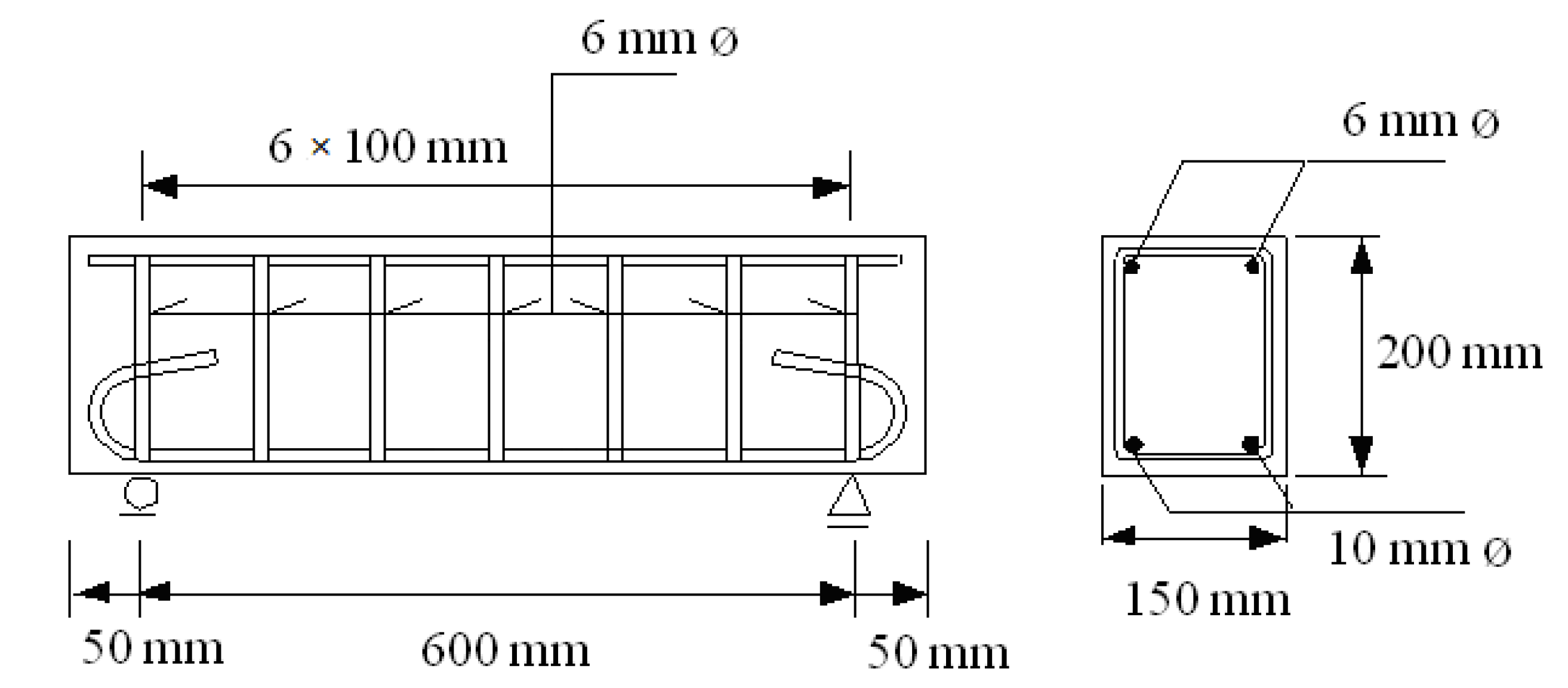
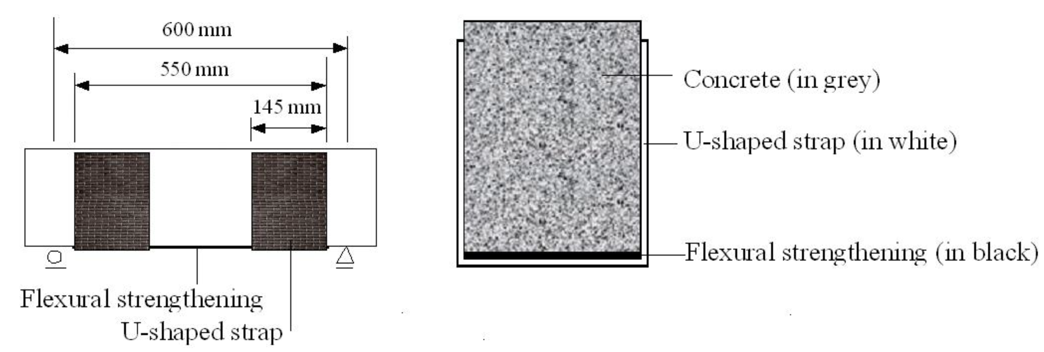
2.1. Test Specimens
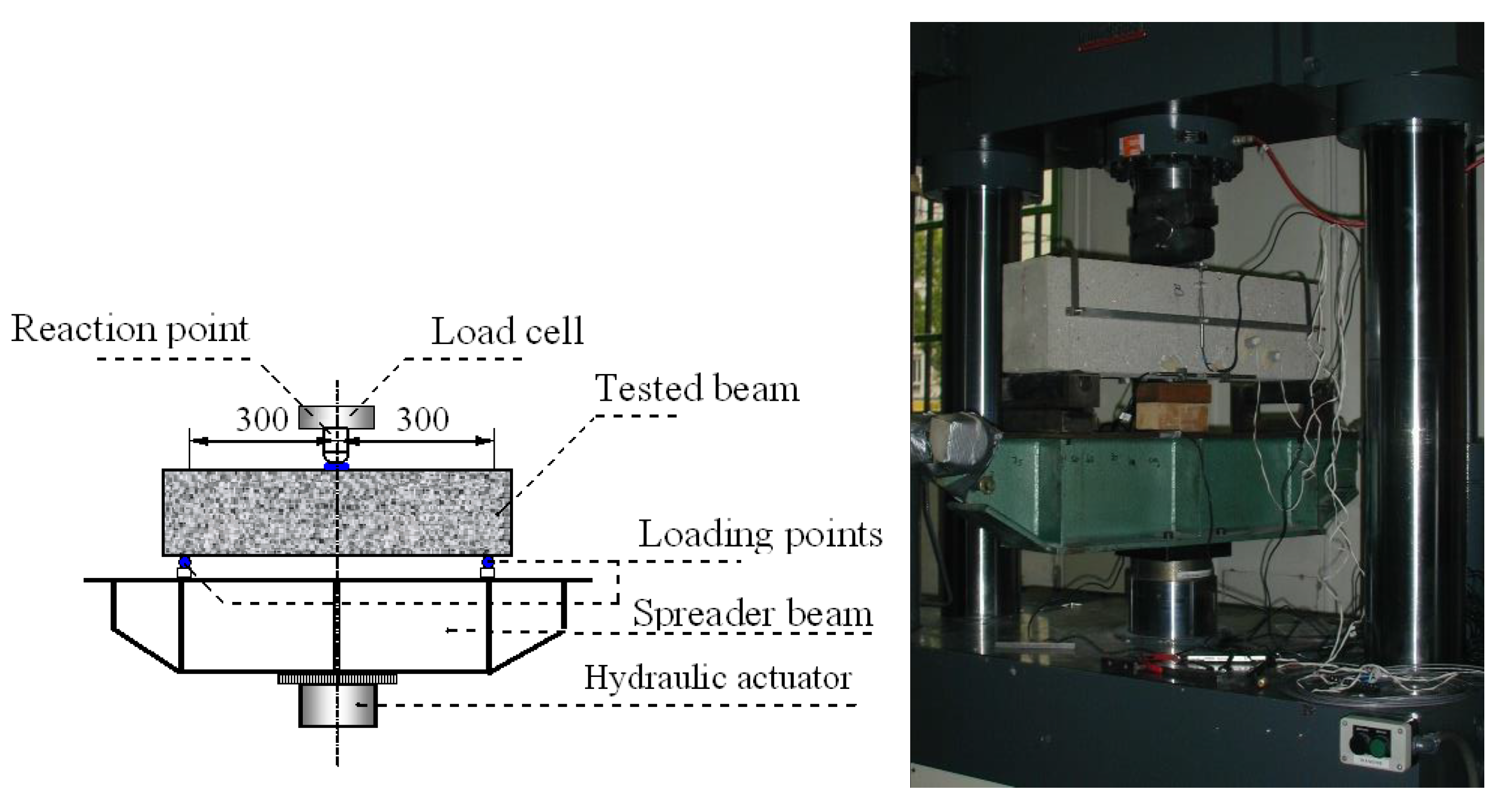
2.2. Test Setup
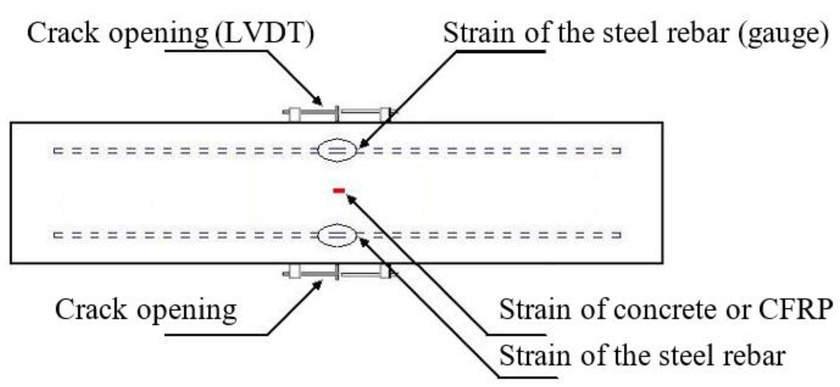
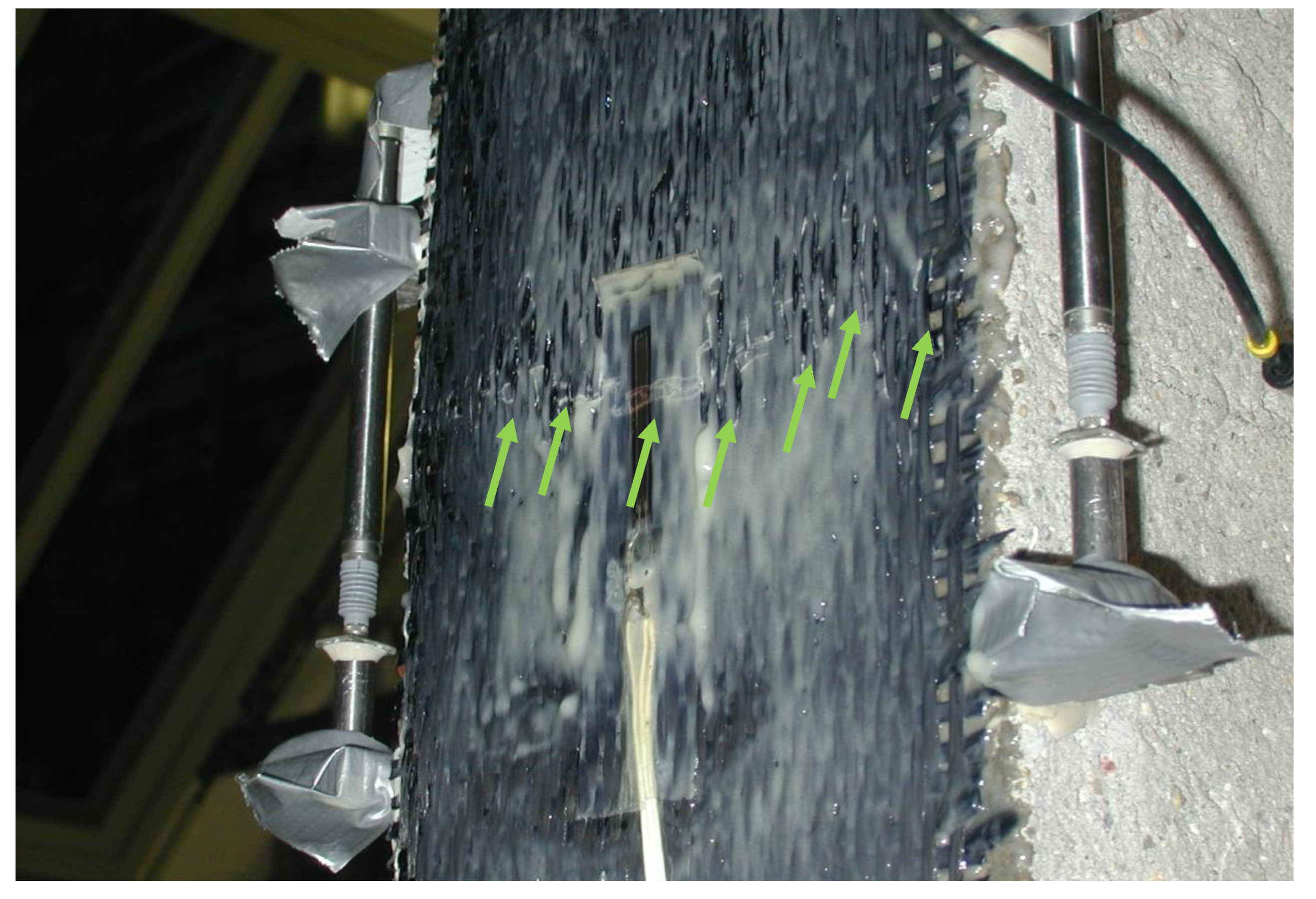
2.3. Monitoring
2.4. Test Procedure
3. Test Result
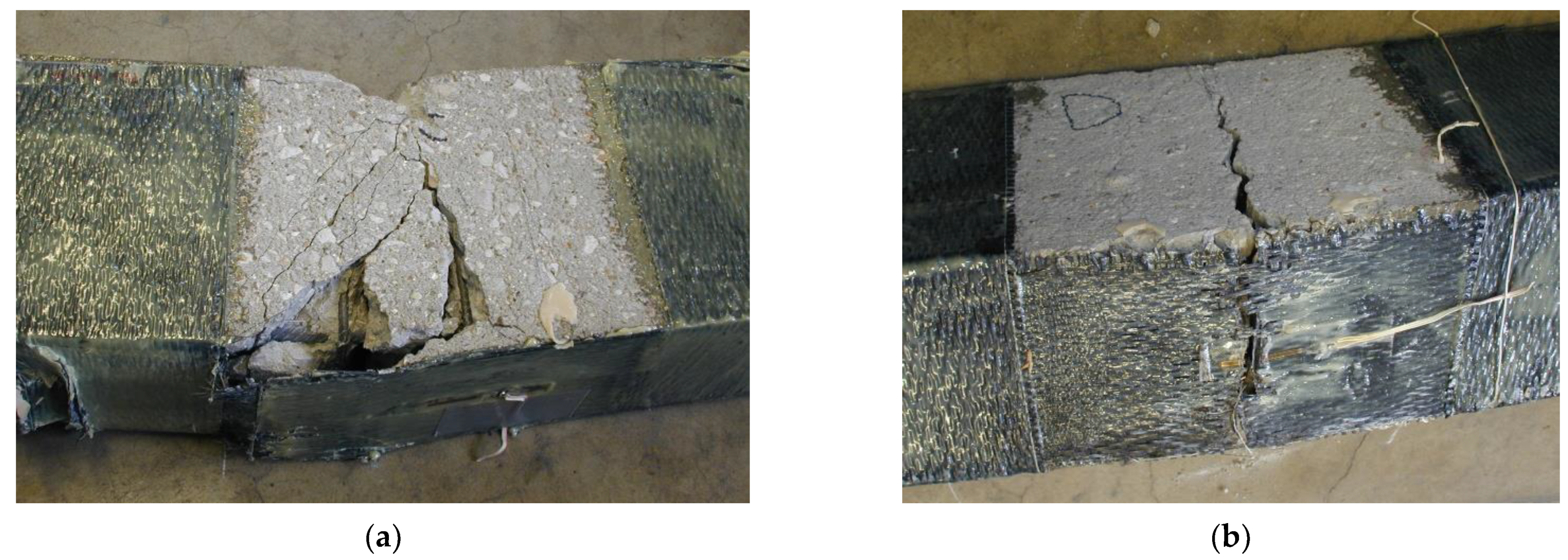
3.1. Failure
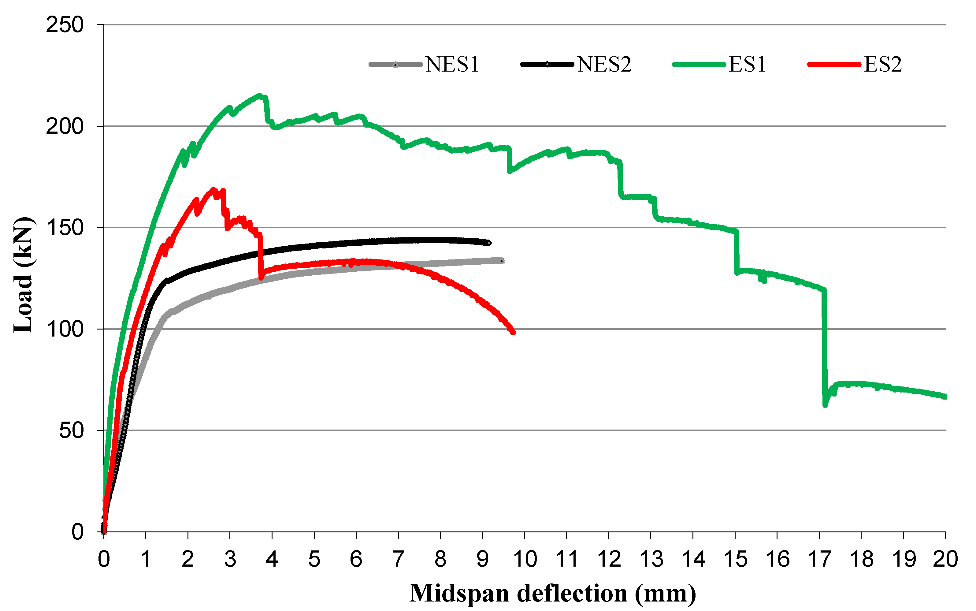
3.2. Carrying Capacity
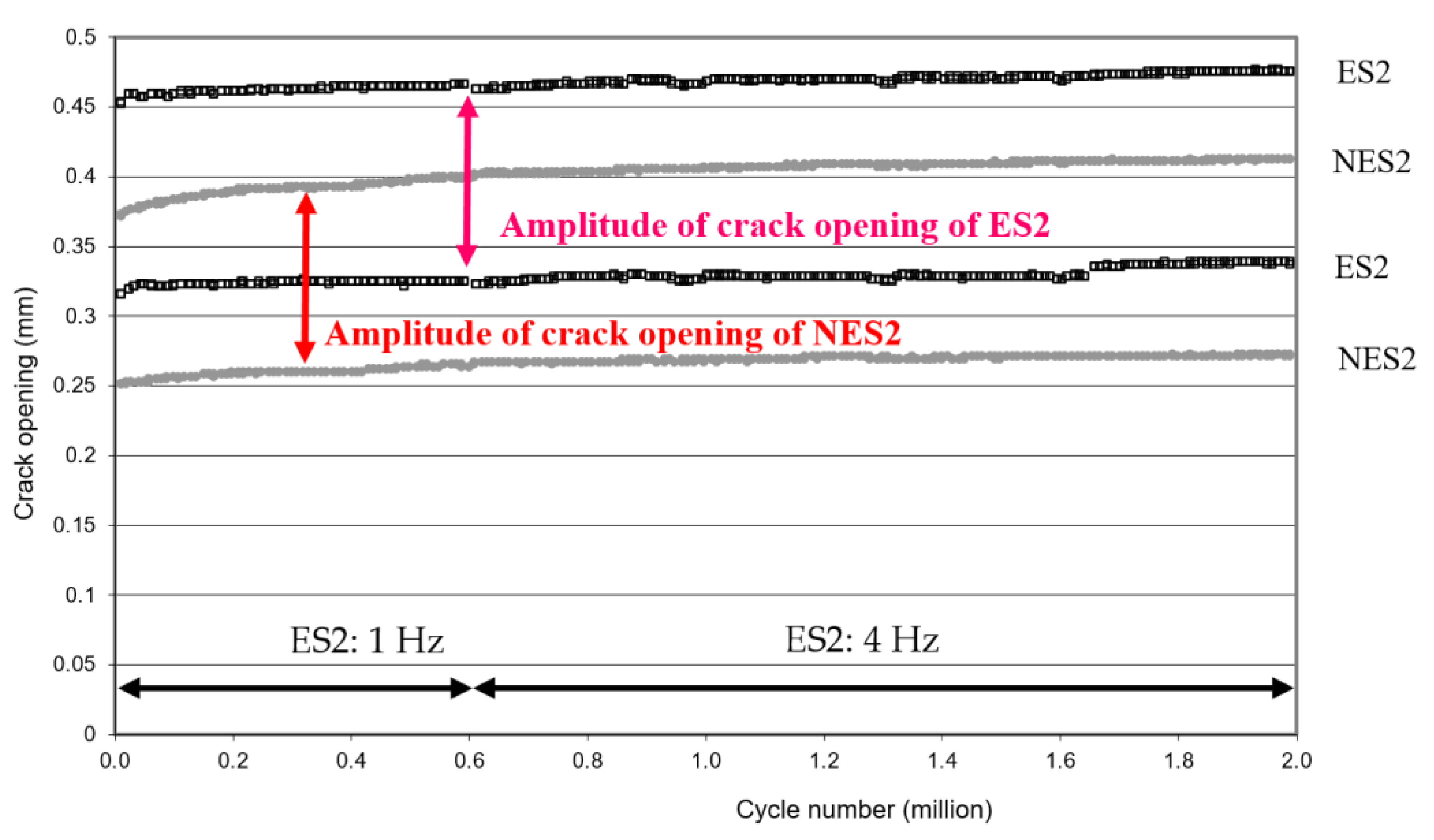
4. Fatigue Behavior and Discussion on the Effectiveness of the External Strengthening
5. Conclusions
Author Contributions
Funding
Data Availability Statement
Conflicts of Interest
References
- Yang, S.I.; Frangopol, D.M.; Neves, L.C. Optimum maintenance strategy for deteriorating bridge structures based on lifetime functions. Eng. Struct. 2006, 28, 196–206. [Google Scholar] [CrossRef] [Green Version]
- Frangopol, D.M. Reliability deterioration and lifetime maintenance cost optimization In Keynote Lecture. In Proceedings of the First International ASRAN et Colloquium on Integrating Structural Reliability Analysis with Advanced Structural Analysis, Glasgow, Scotland, 8–10 July 2002. [Google Scholar]
- Li, G.; Hedlund, S.; Pang, S.-S.; Alaywan, W.; Eggers, J.; Abadie, C. Repair of damaged RC columns using fast curing FRP composites. Compos. B Eng. 2003, 34, 261–271. [Google Scholar] [CrossRef]
- Reed, M.W.; Barnes, R.W.; Schindler, A.K.; Lee, H.-W. Fiber-Reinforced Polymer Strengthening of Concrete Bridges that Remain Open to Traffic. ACI Struct. J. 2005, 102, 823–831. [Google Scholar]
- Harries, K.A.; Aidoo, J.; Zorn, A.; Quattlebaum, J. Deterioration of FRP-to-Concrete Bond Under Fatigue Loading. Advances in Structural Engineering—Special Issue on Bond Behaviour of FRP in Structures. Adv. Struct. Eng. 2006, 9, 779–789. [Google Scholar] [CrossRef]
- Shahawy, M.; Beitelman, T.E. Static and fatigue performance of RC beams strengthened with CFRP laminates. J. Struct. Eng. 1999, 125, 613–621. [Google Scholar] [CrossRef]
- Gheorghiu, C.; Labossiere, P.; Proulx, J. Response of CFRP-strengthened beams under fatigue with different load amplitudes. Constr. Build. Mater. 2007, 21, 756–763. [Google Scholar] [CrossRef]
- Guo, X.; Wang, Y.; Huang, P.; Shu, S. Fatigue behavior of RC beams strengthened with FRP considering the influence of FRP-concrete interface. Int. J. Fatigue 2021, 143, 105977. [Google Scholar] [CrossRef]
- Bonacci, J.F.; Maalej, M. Externally Bonded Fiber-Reinforced Polymer for Rehabilitation of Corrosion Damaged Concrete Beams. ACI Struct. J. 2000, 97, 703–711. [Google Scholar]
- Shahawy, M.; Chaallal, O.; Beitelman, T.E.; El-Saad, A. Flexural Strengthening with Carbon Fiber-Reinforced Polymer Composites of Preloaded Full-Scale Girders. ACI Struct. J. 2001, 98, 735–742. [Google Scholar]
- Yeong-Soo, S.; Chadon, L. Flexural Behavior of Reinforced Concrete Beams Strengthened with Carbon Fiber-Reinforced Polymer Laminates at Different Levels of Sustaining Load. ACI Struct. J. 2003, 100, 231–239. [Google Scholar]
- Takahashi, Y.; Sato, Y. Experimental Investigation of Initially Loaded RC Beams Bonded by CFRP Sheets. In Proceedings of the Third International Conference on Construction Materials: Performance, Innovations and Structural Implications (ConMat’05), Vancouver, BC, Canada, 22–24 August 2005. [Google Scholar]
- Wenwei, W.; Guo, L. Experimental study and analysis of RC beams strengthened with CFRP laminates under sustaining load. Int. J. Solids Struct. 2006, 43, 1372–1387. [Google Scholar] [CrossRef] [Green Version]
- Barnes, R.A.; Mays, G.C. The effect of traffic vibration on adhesive curing during installation of bonded external reinforcement. Proc. Inst. Civ. Eng. Struct. Build. 2001, 146, 403–410. [Google Scholar] [CrossRef]
- EMPA. Bonding of CFRP Strips under Dynamic Load-Static Testing of Prestressed Narrow Slabs Post-Strengthened with CFRP Strips; Report No. 170′569e-1; EMPA: Dübendorf, Switzerland, 1998. [Google Scholar]
- NF EN 12390-3; Testing Hardened Concrete—Part 3: Compressive Strength of Test Specimens. BSI Standards Publication: London, UK, 2003.
- NF EN 12390-6; Testing Hardened Concrete—Part 6: Tensile Splitting Strength of Test Specimens. BSI Standards Publication: London, UK, 2000.
- EN ISO 527-1; Plastics—Determination of Tensile Properties—Part 1: General Principles. International Organization for Standardization: Geneva, Switzerland, 1993.
- Zhou, Y.; Zhang, J.; Li, W.; Hu, B.; Huang, X. Reliability-based design analysis of FRP Shear Strengthened Reinforced Concrete Beams considering different FRP configurations. Compos. Struct. 2020, 237, 111957. [Google Scholar] [CrossRef]
- Wu, Z.Y.; Clément, J.-L.; Tailhan, J.-L.; Boulay, C.; Fakhri, P. Fatigue Test on Damaged reinforced Concrete Specimens Strengthened by Carbon Cloth. In Proceedings of the HPSC 2002, Seville, Spain, 11–13 March 2002; pp. 347–355. [Google Scholar]
- Harries, K.A.; Reeve, B.; Zorn, A. Experimental evaluation of factors affecting monotonic and fatigue behavior of fiber-reinforced polymer-to-concrete bond in reinforced concrete beams. ACI Struct. J. 2007, 104, 667–674. [Google Scholar]
- Ferrier, E.; Bigaud, D.; Hamelin, P.; Bizindavyi, L.; Neale, K.W. Fatigue of CFRPs externally bonded to concrete. Mater. Struct. 2005, 38, 39–46. [Google Scholar] [CrossRef]
- Gheorghiu, C.; Labossiere, P.; Proulx, J. Fatigue and monotonic strength of RC beams strengthened with CFRPs. Compos. Part A Appl. Sci. Manuf. 2006, 37, 1111–1118. [Google Scholar] [CrossRef]
- Macdonald, M.D. Strength of Bonded Shear Joints Subjected to Movement during Cure. Int. J. Cem. Compos. Lightweight Concr. 1981, 3, 267–272. [Google Scholar] [CrossRef]
- Keerthana, K.; Kishen, J.M.C. Effect of loading frequency on flexural fatigue behaviour of concrete. In Proceedings of the 10th International Conference on Fracture Mechanics of Concrete and Concrete Structures (FraMCoS-X), Bayonne, France, 23–26 June 2019. [Google Scholar]
- Gussenhoven, R.; Brena, S.F. Fatigue behavior of reinforced concrete beams strengthened with different FRP laminate configurations. In Proceedings of the 7th International Symposium on Fiber Reinforced Polymer Reinforcement for Reinforced Concrete Structures (FRPRCS-7), Kansas City, MO, USA, 6–9 November 2005. [Google Scholar]
- Wang, Y.C.; Lee, M.G.; Chen, B.C. Experimental study of FRP-strengthened RC bridge girders subjected to fatigue loading. Compos. Struct. 2007, 81, 491–498. [Google Scholar] [CrossRef]
- Wu, Z.Y.; Clement, J.L.; Tailhan, J.L.; Boulay, C.; Fakhri, P. Static and fatigue tests on precracked RC beams strengthened with CFRP sheets. In Proceedings of the 6th International Symposium on Fiber Reinforced Polymer Reinforcement for Concrete Structures (FRPRCS-6), Singapore, 8–10 July 2003. [Google Scholar]
- Benzarti, K.; Chataigner, S.; Quiertant, M.; Marty, C.; Aubagnac, C. Accelerated ageing behaviour of the adhesive bond between concrete specimens and CFRP overlays. Constr. Build. Mater. 2011, 25, 523–538. [Google Scholar] [CrossRef]
- Eveslage, T.; Aidoo, J.; Harries, K.A.; Bro, W. Effect of Variations in Practice of ASTM D7522 Standard Pull-Off Test for FRP-Concrete Interfaces. J. Test. Eval. 2010, 38, 424–430. [Google Scholar]
- Houhou, N.; Benzarti, K.; Quiertant, M.; Chataigner, S.; Fléty, A.; Marty, C. Analysis of the creep behaviour of FRP-concrete bonded assemblies. J. Adhes. Sci. Technol. 2014, 28, 1345–1366. [Google Scholar] [CrossRef]
- Ferrier, E.; Quiertant, M.; Benzarti, K.; Hamelin, P. Influence of the properties of externally bonded CFRP on the shear behavior of concrete/composite adhesive joints. Compos. Part B Eng. 2010, 41, 354–362. [Google Scholar] [CrossRef]
- Chataigner, S.; Caron, J.F.; Benzarti, K.; Quiertant, M.; Aubagnac, C. Characterization of FRP-to-concrete bonded interface- Description of the single lap shear test. Eur. J. Environ. Civ. Eng. 2009, 13, 1073–1082. [Google Scholar] [CrossRef]
- Avis Technique 3/07-540. Available online: https://evaluation.cstb.fr/fr/avis-technique/detail/3-07-540/ (accessed on 1 October 2021).


| Young’s Modulus | 31.8 GPa |
| Poisson’s ratio | 0.19 |
| Tensile strength (from splitting tests) | 3.1 MPa |
| Compressive strength | 41.2 MPa |
| Resin Part | Hardener Part | |
|---|---|---|
| Main organic constituents (reported by manufacturers) | Bisphenol A epichlorhydrin oxirane | Alkyletheramines Diethylenetriamine (DETA) |
| Hardened epoxy | ||
| Tensile modulus (measured) | 2.3 ± 0.2 GPa | |
| Tensile strength (measured) | 29.3 ± 1.2 MPa | |
| Ultimate strain (measured) | 2.4 ± 0.3% | |
| Fibers (12 k—Torayca) Nominal-Min | CFRP (One Layer) Average | |
|---|---|---|
| Thickness (mm) | x | 0.43 |
| Young’s modulus (GPa) | 230–221 | 105 (wrap direction) |
| Tensile strength (MPa) | 4900–4510 | 1700 (wrap direction) |
| Step No. 1 Pre-Cracking | Step No. 2 CFRP Bonding | Step No. 3 Cure of Epoxy | Step No. 4 Fatigue Cycles | Step No. 5 Failure | |
|---|---|---|---|---|---|
| NES1 | No | No | No | No | Yes |
| NES2 | Yes | No | No | 2 million cycles | Yes |
| ES1 | Yes | Yes | 7 days cure without any cycles | 2 million cycles | Yes |
| ES2 | Yes | Yes (during cycles) | 7 days with 604,800 bending cycles during cure of the epoxy | 1,395,200 cycles | Yes |
| Maximum Load | Failure Mode | Deflection at Failure | |
|---|---|---|---|
| Beam NES1 | 133.7 kN | Tensile rupture of a longitudinal rebar | 9.46 mm |
| Beam NES2 | 143.8 kN | Tensile rupture of a longitudinal rebar | 9.16 mm |
| Beam ES1 | 215.0 kN | Tensile rupture of the CFRP due to diagonal crack | (>20 mm) |
| Beam ES2 | 168.6 kN | Tensile CFRP rupture below the initial crack | 9.73 mm |
Publisher’s Note: MDPI stays neutral with regard to jurisdictional claims in published maps and institutional affiliations. |
© 2022 by the authors. Licensee MDPI, Basel, Switzerland. This article is an open access article distributed under the terms and conditions of the Creative Commons Attribution (CC BY) license (https://creativecommons.org/licenses/by/4.0/).
Share and Cite
Quiertant, M.; Boulay, C.; Siegert, L.; Tourneur, C. Effect of the Cyclic Crack Opening-Closure during Epoxy-Curing Period of a CFRP Strengthening System Bonded on Concrete Substrate. Appl. Mech. 2022, 3, 88-102. https://0-doi-org.brum.beds.ac.uk/10.3390/applmech3010006
Quiertant M, Boulay C, Siegert L, Tourneur C. Effect of the Cyclic Crack Opening-Closure during Epoxy-Curing Period of a CFRP Strengthening System Bonded on Concrete Substrate. Applied Mechanics. 2022; 3(1):88-102. https://0-doi-org.brum.beds.ac.uk/10.3390/applmech3010006
Chicago/Turabian StyleQuiertant, Marc, Claude Boulay, Laurent Siegert, and Christian Tourneur. 2022. "Effect of the Cyclic Crack Opening-Closure during Epoxy-Curing Period of a CFRP Strengthening System Bonded on Concrete Substrate" Applied Mechanics 3, no. 1: 88-102. https://0-doi-org.brum.beds.ac.uk/10.3390/applmech3010006