Simulating Metaphyseal Fracture Healing in the Distal Radius

 , , , and
Abstract
:1. Introduction
2. Materials and Methods
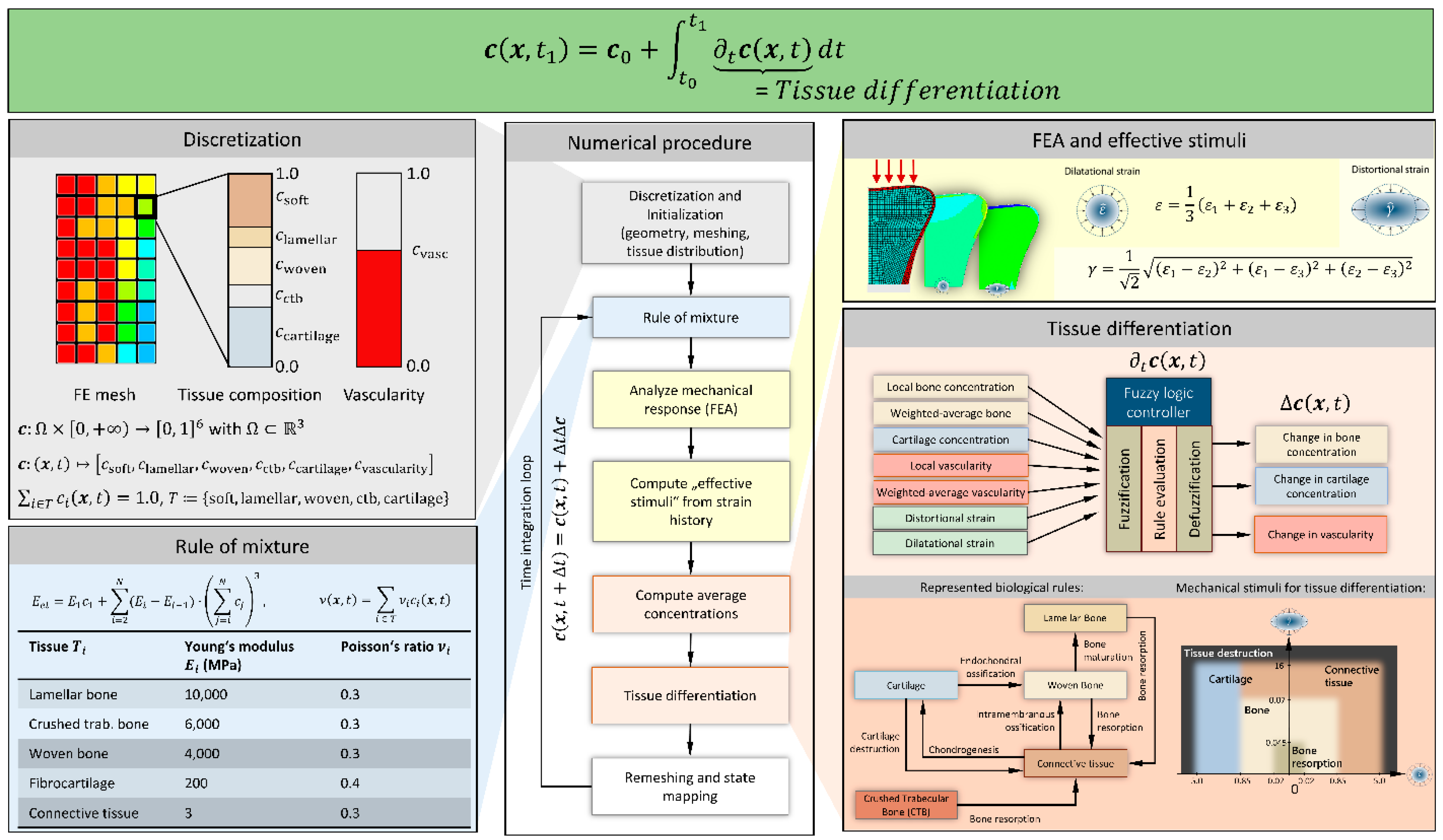
2.1. Tissue Differentiation
2.2. Metaphyseal Healing
2.3. Homogenized Material for Trabecular Structure
2.4. Rule of Mixture
2.5. Modelling of a Compression Fracture
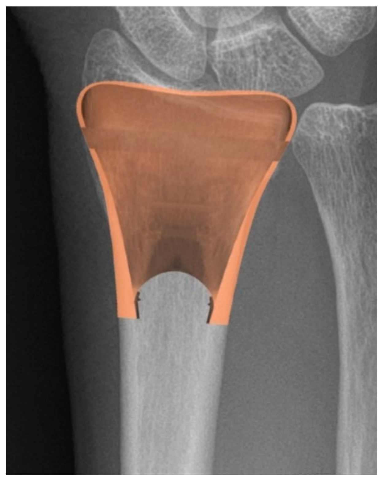
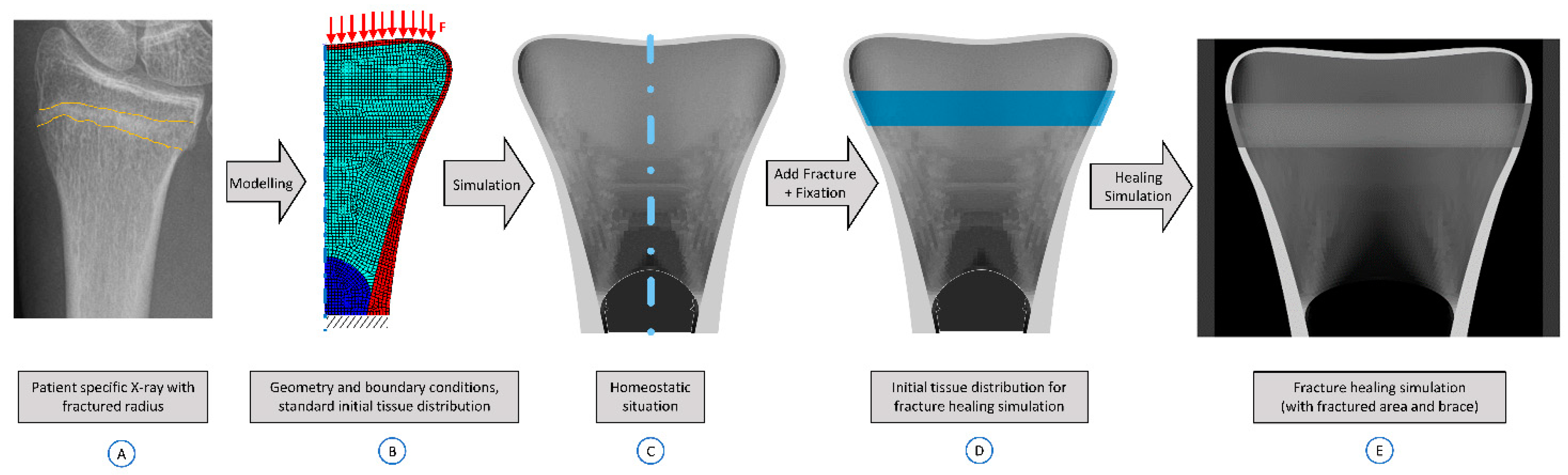
2.6. Application to Distal Radius Fractures
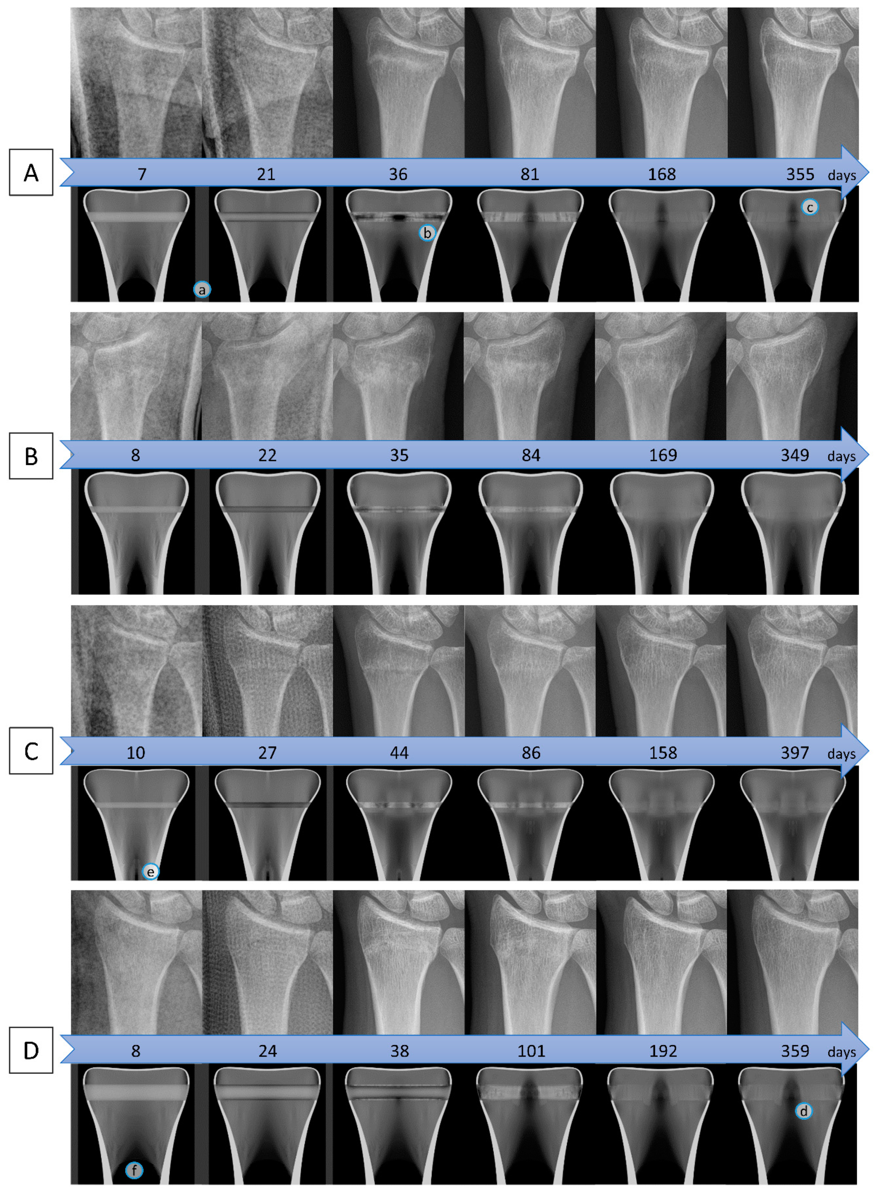
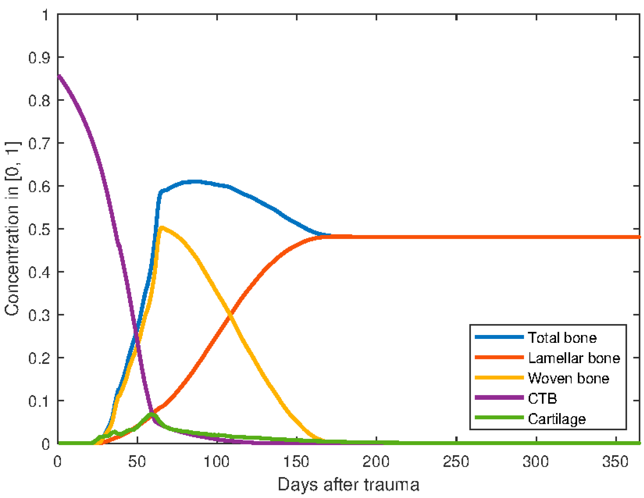
3. Results
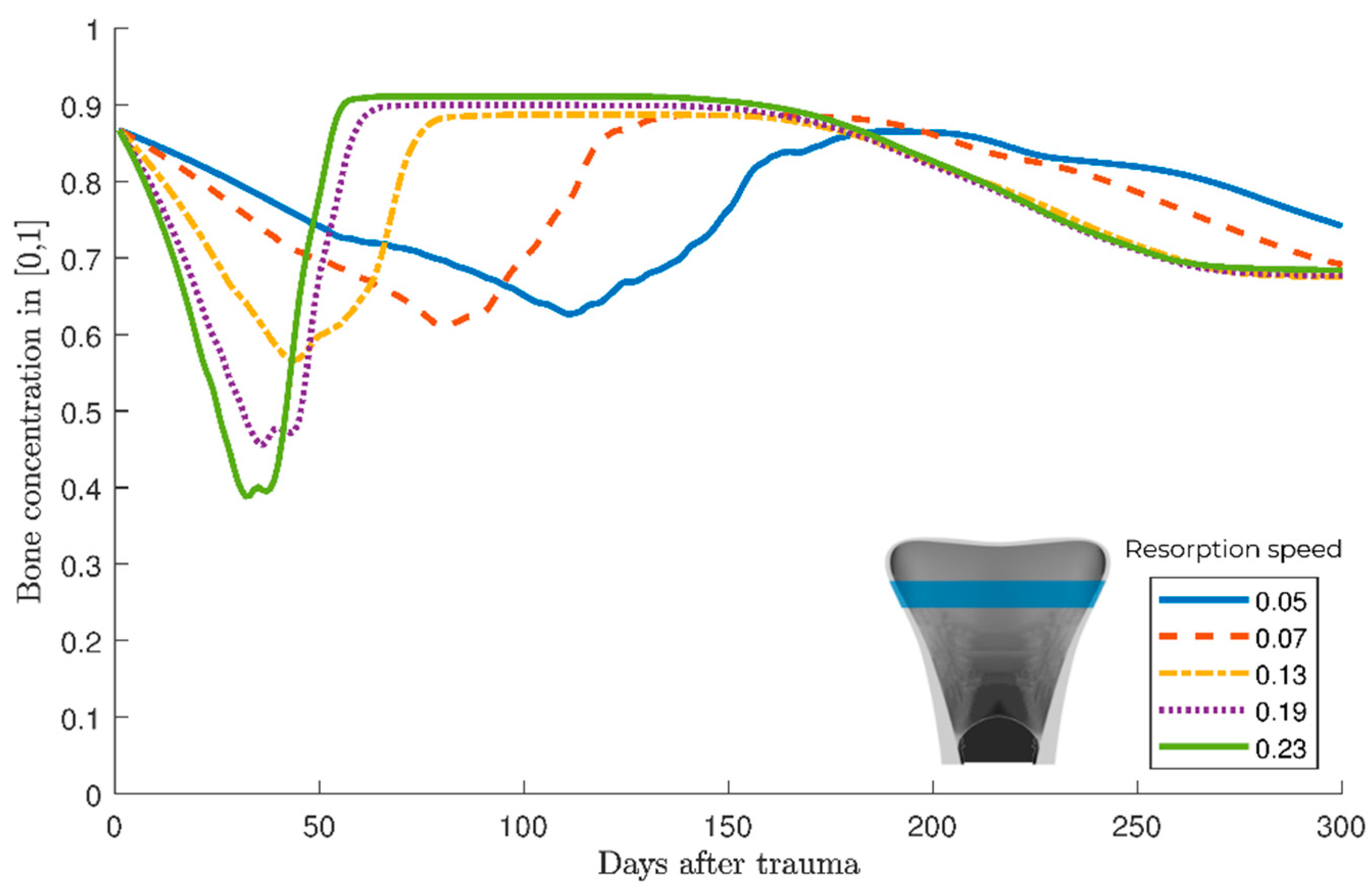
Parameter variation
4. Discussion
5. Conclusions
Supplementary Materials
Author Contributions
Funding
Institutional Review Board Statement
Informed Consent Statement
Data Availability Statement
Conflicts of Interest
References
- Bonafede, M.; Espindle, D.; Bower, A.G. The direct and indirect costs of long bone fractures in a working age US population. J. Med. Econ. 2013, 16, 169–178. [Google Scholar] [CrossRef]
- MacIntyre, N.J.; Dewan, N. Epidemiology of distal radius fractures and factors predicting risk and prognosis. J. Hand Ther. 2016, 29, 136–145. [Google Scholar] [CrossRef] [PubMed]
- Porrino, J.A.; Maloney, E.; Scherer, K.; Mulcahy, H.; Ha, A.S.; Allan, C. Fracture of the distal radius: Epidemiology and premanagement radiographic characterization. AJR Am. J. Roentgenol. 2014, 203, 551–559. [Google Scholar] [CrossRef] [PubMed]
- De Putter, C.E.; van Beeck, E.F.; Looman, C.W.N.; Toet, H.; Hovius, S.E.R.; Selles, R.W. Trends in Wrist Fractures in Children and Adolescents, 1997–2009. J. Hand Surg. Am. 2011, 36, 1810–1815.e2. [Google Scholar] [CrossRef]
- Jayakumar, P.; Teunis, T.; Giménez, B.B.; Verstreken, F.; Di Mascio, L.; Jupiter, J.B. AO Distal Radius Fracture Classification: Global Perspective on Observer Agreement. J. Wrist Surg. 2017, 6, 46–53. [Google Scholar] [CrossRef] [PubMed] [Green Version]
- Müller, M.E.; Koch, P.; Nazarian, S.; Schatzker, J. The Comprehensive Classification of Fractures of Long Bones; Springer: Berlin/Heidelberg, Germany, 1990; ISBN 978-3-540-18165-1. [Google Scholar]
- Lippisch, R.; Lucas, B.; Schüttrumpf, J.P.; Piatek, S.; Walcher, F. Distale Radiusfraktur. Trauma Berufskrankh 2016, 18, 413–420. [Google Scholar] [CrossRef] [Green Version]
- Meena, S.; Sharma, P.; Sambharia, A.K.; Dawar, A. Fractures of distal radius: An overview. J. Family Med. Prim. Care 2014, 3, 325–332. [Google Scholar] [CrossRef]
- Jarry, L.; Uhthoff, H.K. Differences in healing of metaphyseal and diaphyseal fractures. Can. J. Surg. 1971, 14, 127–135. [Google Scholar]
- Uhthoff, H.K.; Rahn, B.A. Healing patterns of metaphyseal fractures. Clin. Orthop. Relat. Res. 1981, 295–303. [Google Scholar] [CrossRef]
- Claes, L.; Veeser, A.; Göckelmann, M.; Simon, U.; Ignatius, A. A novel model to study metaphyseal bone healing under defined biomechanical conditions. Arch. Orthop. Trauma Surg. 2009, 129, 923–928. [Google Scholar] [CrossRef]
- Claes, L.; Reusch, M.; Göckelmann, M.; Ohnmacht, M.; Wehner, T.; Amling, M.; Beil, F.T.; Ignatius, A. Metaphyseal fracture healing follows similar biomechanical rules as diaphyseal healing. J. Orthop. Res. 2011, 29, 425–432. [Google Scholar] [CrossRef]
- Aspenberg, P.; Sandberg, O. Distal radial fractures heal by direct woven bone formation. Acta Orthop. 2013, 84, 297–300. [Google Scholar] [CrossRef] [PubMed] [Green Version]
- Sandberg, O.; Aspenberg, P. Inter-trabecular bone formation: A specific mechanism for healing of cancellous bone. Acta Orthop. 2016, 87, 459–465. [Google Scholar] [CrossRef] [Green Version]
- Lacroix, D.; Prendergast, P.J. A mechano-regulation model for tissue differentiation during fracture healing: Analysis of gap size and loading. J. Biomech. 2002, 35, 1163–1171. [Google Scholar] [CrossRef]
- Doblaré, M.; García, J.M.; Gómez, M.J. Modelling bone tissue fracture and healing: A review. Eng. Fract. Mech. 2004, 71, 1809–1840. [Google Scholar] [CrossRef]
- Gómez-Benito, M.J.; García-Aznar, J.M.; Kuiper, J.H.; Doblaré, M. A 3D computational simulation of fracture callus formation: Influence of the stiffness of the external fixator. J. Biomech. Eng. 2006, 128, 290–299. [Google Scholar] [CrossRef]
- Isaksson, H.; van Donkelaar, C.C.; Huiskes, R.; Ito, K. Corroboration of mechanoregulatory algorithms for tissue differentiation during fracture healing: Comparison with in vivo results. J. Orthop. Res. 2006, 24, 898–907. [Google Scholar] [CrossRef] [PubMed]
- Geris, L.; Gerisch, A.; Sloten, J.V.; Weiner, R.; van Oosterwyck, H. Angiogenesis in bone fracture healing: A bioregulatory model. J. Theor. Biol. 2008, 251, 137–158. [Google Scholar] [CrossRef]
- Checa, S.; Prendergast, P.J. A mechanobiological model for tissue differentiation that includes angiogenesis: A lattice-based modeling approach. Ann. Biomed. Eng 2009, 37, 129–145. [Google Scholar] [CrossRef]
- Simon, U.; Augat, P.; Utz, M.; Claes, L. A numerical model of the fracture healing process that describes tissue development and revascularisation. Comput. Methods Biomech. Biomed. Eng. 2011, 14, 79–93. [Google Scholar] [CrossRef]
- Ghiasi, M.S.; Chen, J.; Vaziri, A.; Rodriguez, E.K.; Nazarian, A. Bone fracture healing in mechanobiological modeling: A review of principles and methods. Bone Rep. 2017, 6, 87–100. [Google Scholar] [CrossRef]
- Wilson, C.J.; Schütz, M.A.; Epari, D.R. Computational simulation of bone fracture healing under inverse dynamisation. Biomech. Model. Mechanobiol. 2017, 16, 5–14. [Google Scholar] [CrossRef] [PubMed] [Green Version]
- Ren, T.; Dailey, H.L. Mechanoregulation modeling of bone healing in realistic fracture geometries. Biomech. Modeling Mechanobiol. 2020. [Google Scholar] [CrossRef] [PubMed]
- Shefelbine, S.J.; Augat, P.; Claes, L.; Simon, U. Trabecular bone fracture healing simulation with finite element analysis and fuzzy logic. J. Biomech. 2005, 38, 2440–2450. [Google Scholar] [CrossRef] [PubMed]
- Simon, U.; Shefelbine, S.J.; Augat, P.; Claes, L. Simulation of fracture healing in metaphyseal bone. J. Biomech. 2006, 39, S456. [Google Scholar] [CrossRef]
- Stock, K.; Marano, G.; Blauth, M.; Arora, R.; Müller, R.; Christen, P. Local In Vivo Assessment of Human Distal Radius Fractures by Time-Lapse HR-pQCTradius Fractures. In Proceedings of the 28th Joint Annual Meeting of The Swiss Association against Osteoporosis (SVGO) and the Swiss Bone and Mineral Society (SBMS), Bern, Switzerland, 3 May 2018. [Google Scholar]
- Niemeyer, F.; Claes, L.; Ignatius, A.; Meyers, N.; Simon, U. Simulating lateral distraction osteogenesis. PLoS ONE 2018, 13, e0194500. [Google Scholar] [CrossRef] [PubMed]
- Steiner, M.; Claes, L.; Ignatius, A.; Niemeyer, F.; Simon, U.; Wehner, T. Prediction of fracture healing under axial loading, shear loading and bending is possible using distortional and dilatational strains as determining mechanical stimuli. J. R. Soc. Interface 2013, 10, 20130389. [Google Scholar] [CrossRef] [Green Version]
- Steiner, M.; Claes, L.; Ignatius, A.; Simon, U.; Wehner, T. Disadvantages of interfragmentary shear on fracture healing--mechanical insights through numerical simulation. J. Orthop. Res. 2014, 32, 865–872. [Google Scholar] [CrossRef]
- Steiner, M.; Claes, L.; Ignatius, A.; Simon, U.; Wehner, T. Numerical simulation of callus healing for optimization of fracture fixation stiffness. PLoS ONE 2014, 9, e101370. [Google Scholar] [CrossRef] [Green Version]
- Wehner, T.; Claes, L.; Niemeyer, F.; Nolte, D.; Simon, U. Influence of the fixation stability on the healing time--a numerical study of a patient-specific fracture healing process. Clin. Biomech. 2010, 25, 606–612. [Google Scholar] [CrossRef]
- Wehner, T.; Steiner, M.; Ignatius, A.; Claes, L. Prediction of the time course of callus stiffness as a function of mechanical parameters in experimental rat fracture healing studies—A numerical study. PLoS ONE 2014, 9, e115695. [Google Scholar] [CrossRef]
- Pauwels, F. Eine neue Theorie ber den Einflu mechanischer Reize auf die Differenzierung der Sttzgewebe. Z. Anat. Entwickl. Gesch. 1960, 121, 478–515. [Google Scholar] [CrossRef]
- Claes, L.; Heigele, C.A. Magnitudes of local stress and strain along bony surfaces predict the course and type of fracture healing. J. Biomech. 1999, 32, 255–266. [Google Scholar] [CrossRef]
- Arias-Moreno, A.J.; Hosseini, H.S.; Bevers, M.; Ito, K.; Zysset, P.; van Rietbergen, B. Validation of distal radius failure load predictions by homogenized- and micro-finite element analyses based on second-generation high-resolution peripheral quantitative CT images. Osteoporos. Int. 2019, 30, 1433–1443. [Google Scholar] [CrossRef] [Green Version]
- Hosseini, H.S.; Dünki, A.; Fabech, J.; Stauber, M.; Vilayphiou, N.; Pahr, D.; Pretterklieber, M.; Wandel, J.; van Rietbergen, B.; Zysset, P.K. Fast estimation of Colles’ fracture load of the distal section of the radius by homogenized finite element analysis based on HR-pQCT. Bone 2017, 97, 65–75. [Google Scholar] [CrossRef]
- MacNeil, J.A.; Boyd, S.K. Bone strength at the distal radius can be estimated from high-resolution peripheral quantitative computed tomography and the finite element method. Bone 2008, 42, 1203–1213. [Google Scholar] [CrossRef] [PubMed]
- Varga, P.; Dall’Ara, E.; Pahr, D.H.; Pretterklieber, M.; Zysset, P.K. Validation of an HR-pQCT-based homogenized finite element approach using mechanical testing of ultra-distal radius sections. Biomech. Modeling Mechanobiol. 2011, 10, 431–444. [Google Scholar] [CrossRef]
- Carter, D.R.; Hayes, W.C. The compressive behavior of bone as a two-phase porous structure. J. Bone Joint Surg. Am. 1977, 59, 954–962. [Google Scholar] [CrossRef] [PubMed]
- Pietsch, M.; Niemeyer, F.; Simon, U.; Ignatius, A.; Urban, K. Modelling the fracture-healing process as a moving-interface problem using an interface-capturing approach. Comput. Methods Biomech. Biomed. Eng. 2018, 21, 512–520. [Google Scholar] [CrossRef] [Green Version]
- de Jong, J.J.A.; Heyer, F.L.; Arts, J.J.C.; Poeze, M.; Keszei, A.P.; Willems, P.C.; van Rietbergen, B.; Geusens, P.P.; van den Bergh, J.P.W. Fracture Repair in the Distal Radius in Postmenopausal Women: A Follow-Up 2 Years Postfracture Using HRpQCT. J. Bone Miner. Res. 2016, 31, 1114–1122. [Google Scholar] [CrossRef] [PubMed]
- de Jong, J.J.A.; Willems, P.C.; Arts, J.J.; Bours, S.G.P.; Brink, P.R.G.; van Geel, T.A.C.M.; Poeze, M.; Geusens, P.P.; van Rietbergen, B.; van den Bergh, J.P.W. Assessment of the healing process in distal radius fractures by high resolution peripheral quantitative computed tomography. Bone 2014, 64, 65–74. [Google Scholar] [CrossRef] [Green Version]
- Meyer, U.; de Jong, J.J.; Bours, S.G.P.; Keszei, A.P.; Arts, J.J.; Brink, P.R.G.; Menheere, P.; van Geel, T.A.C.M.; van Rietbergen, B.; van den Bergh, J.P.W.; et al. Early changes in bone density, microarchitecture, bone resorption, and inflammation predict the clinical outcome 12 weeks after conservatively treated distal radius fractures: An exploratory study. J. Bone Miner. Res. 2014, 29, 2065–2073. [Google Scholar] [CrossRef]
- Loi, F.; Córdova, L.A.; Pajarinen, J.; Lin, T.-H.; Yao, Z.; Goodman, S.B. Inflammation, fracture and bone repair. Bone 2016, 86, 119–130. [Google Scholar] [CrossRef] [Green Version]
- Schlickewei, C.W.; Kleinertz, H.; Thiesen, D.M.; Mader, K.; Priemel, M.; Frosch, K.-H.; Keller, J. Current and Future Concepts for the Treatment of Impaired Fracture Healing. Int. J. Mol. Sci. 2019, 20, 5805. [Google Scholar] [CrossRef] [PubMed] [Green Version]
- Chen, W.T.; Han, D.C.; Zhang, P.X.; Han, N.; Kou, Y.H.; Yin, X.F.; Jiang, B.G. A special healing pattern in stable metaphyseal fractures. Acta Orthop. 2015, 86, 238–242. [Google Scholar] [CrossRef] [PubMed]
- Thurner, P.J.; Erickson, B.; Jungmann, R.; Schriock, Z.; Weaver, J.C.; Fantner, G.E.; Schitter, G.; Morse, D.E.; Hansma, P.K. High-speed photography of compressed human trabecular bone correlates whitening to microscopic damage. Eng. Fract. Mech. 2007, 74, 1928–1941. [Google Scholar] [CrossRef]
- Hambli, R. Evaluation of apparent stress and strain at fracture of human trabecular bone under quasi-static compression load using micro-finite element simulations, Chapter of Evaluation of Apparent Stress and Strain at the Fracture of the Human Trabecular Bone under Quasi-Static Compression Load Using Micro-CT Finite Element Simulation. In Trabecular BONE: Morphology, biomechanics and clinical implications; Nova Science Publishers: Hauppauge, NY, USA, 2013; pp. 77–114. [Google Scholar]
- Wu, D.; Isaksson, P.; Ferguson, S.J.; Persson, C. Young’s modulus of trabecular bone at the tissue level: A review. Acta Biomater. 2018, 78, 1–12. [Google Scholar] [CrossRef] [PubMed]
- Atkins, P.R.; Stock, K.; Horling, L.; Ohs, N.; Collins, C.J.; Christen, P.; Blauth, M.; Müller, R. Bone Resorption and Formation Rates are Reduced in Late Stage Healing of Dominant Arm Distal Radius Fractures; Orthopaedic Research Society (ORS): Phoenix, AZ, USA, 2020. [Google Scholar]
- Christen, P.; Boutroy, S.; Ellouz, R.; Chapurlat, R.; van Rietbergen, B. Least-detectable and age-related local in vivo bone remodelling assessed by time-lapse HR-pQCT. PLoS ONE 2018, 13, e0191369. [Google Scholar] [CrossRef] [PubMed] [Green Version]
- Engelhardt, L.; Vogelaar, D.; Weresch, P.; Urban, K.; Simon, U. A Musculoskeletal Inverse-Dynamics Model of the Human Hand Including Intrinsic Muscles; WCB: Dublin, Ireland, 2018. [Google Scholar]
- Engelhardt, L.; Melzner, M.; Havelkova, L.; Christen, P.; Dendorfer, S.; Simon, U. A New Musculoskeletal Anybody™ Detailed Hand Model; Annual meeting of European Society of Biomechanics: Vienna, Austria, 2019. [Google Scholar]
- Engelhardt, L.; Melzner, M.; Havelkova, L.; Christen, P.; Dendorfer, S.; Simon, U. A new musculoskeletal AnyBody™ detailed hand model. J. Comput. Methods Biomech. Biomed. Eng. 2020. [Google Scholar] [CrossRef] [PubMed]
- Schmidt, V.E.; Somerset, J.H.; Porter, R.E. Mechanical properties of orthopedic plaster bandages. J. Biomech. 1973, 6, 173–185. [Google Scholar] [CrossRef]
- Banzer, D.; Fabian, C.; Andresen, R.; Banzer, J.P.; Felsenberg, D.; Reisinger, W.; Neher, K.M. Knochendichte von Spongiosa und Kortikalis der Lendenwirbelsäule. Beziehungen zu Geschlecht, Alter und Wirbeldeformitäten in einem regionalen Kollektiv der europäischen Studie zur vertebralen Osteoporose (EVOS). Med. Klin. 1998, 93 Suppl. 2, 56–62, 64–65. [Google Scholar] [CrossRef] [PubMed]
- Burchardt, H. The biology of bone graft repair. Clinical Orthopaedics and Related Research 1983, 174, 28–42. [Google Scholar] [CrossRef]


| Resorption Potential | |
|---|---|
| Perfused tissue (pp) | 0.8 |
| Soft tissue (ps) | 1.0 |
| CTB (pctb) | 0.1 |
| Tissue Concentrations | Variable |
| Woven bone | |
| Lamellar bone | |
| Crushed trabecular bone | |
| Cartilage | |
| Connective/soft tissue |
Publisher’s Note: MDPI stays neutral with regard to jurisdictional claims in published maps and institutional affiliations. |
© 2021 by the authors. Licensee MDPI, Basel, Switzerland. This article is an open access article distributed under the terms and conditions of the Creative Commons Attribution (CC BY) license (http://creativecommons.org/licenses/by/4.0/).
Share and Cite
Engelhardt, L.; Niemeyer, F.; Christen, P.; Müller, R.; Stock, K.; Blauth, M.; Urban, K.; Ignatius, A.; Simon, U. Simulating Metaphyseal Fracture Healing in the Distal Radius. Biomechanics 2021, 1, 29-42. https://0-doi-org.brum.beds.ac.uk/10.3390/biomechanics1010003
Engelhardt L, Niemeyer F, Christen P, Müller R, Stock K, Blauth M, Urban K, Ignatius A, Simon U. Simulating Metaphyseal Fracture Healing in the Distal Radius. Biomechanics. 2021; 1(1):29-42. https://0-doi-org.brum.beds.ac.uk/10.3390/biomechanics1010003
Chicago/Turabian StyleEngelhardt, Lucas, Frank Niemeyer, Patrik Christen, Ralph Müller, Kerstin Stock, Michael Blauth, Karsten Urban, Anita Ignatius, and Ulrich Simon. 2021. "Simulating Metaphyseal Fracture Healing in the Distal Radius" Biomechanics 1, no. 1: 29-42. https://0-doi-org.brum.beds.ac.uk/10.3390/biomechanics1010003