
Geomechanical Behaviour of Uncemented Expanded Polystyrene (EPS) Beads–Clayey Soil Mixtures as Lightweight Fill

 , ,
, ,  ,
,
Abstract
:1. Introduction
2. Experimental Testing Programme
2.1. Materials
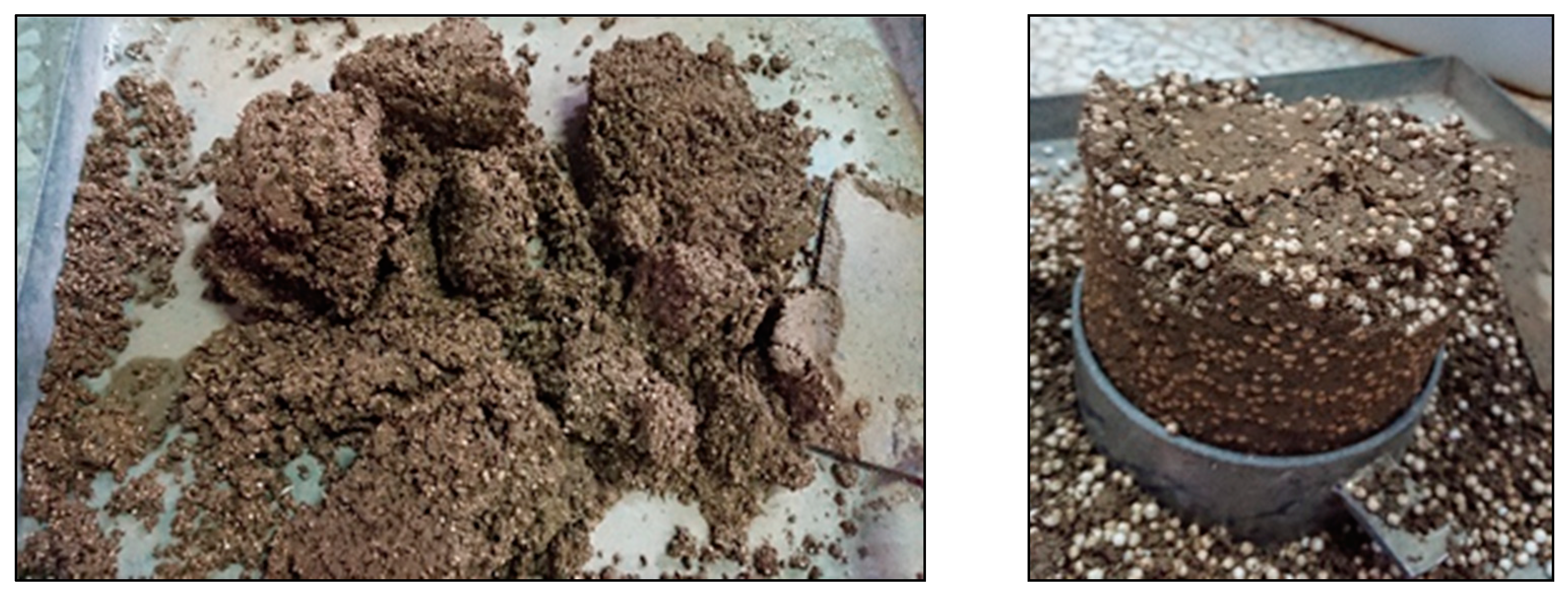
2.2. Soil–EPS Beads Mixing Ratio and Test-Specimen Preparation
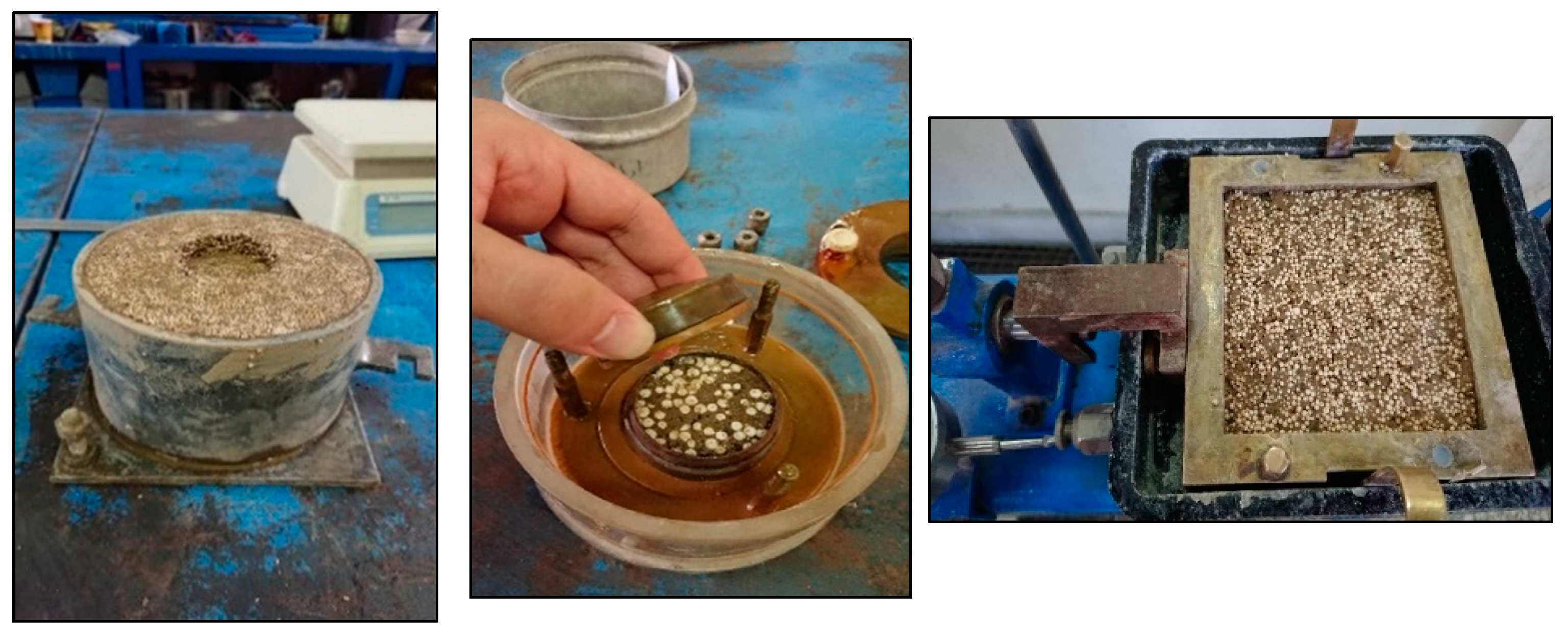
2.3. Experimental Methods
3. Experimental Results and Analysis
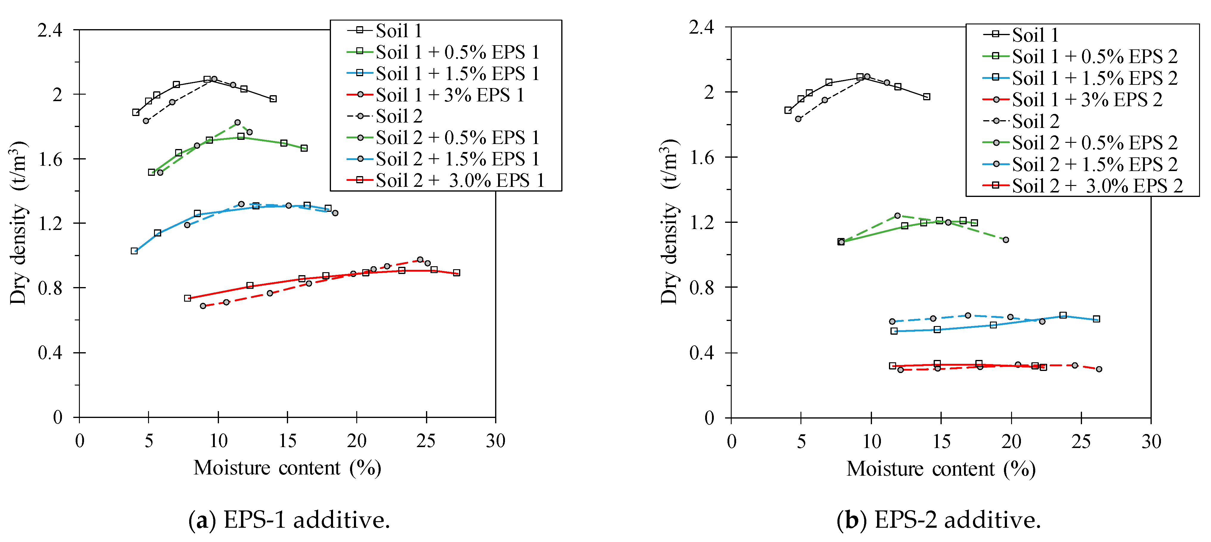
3.1. SP Compaction
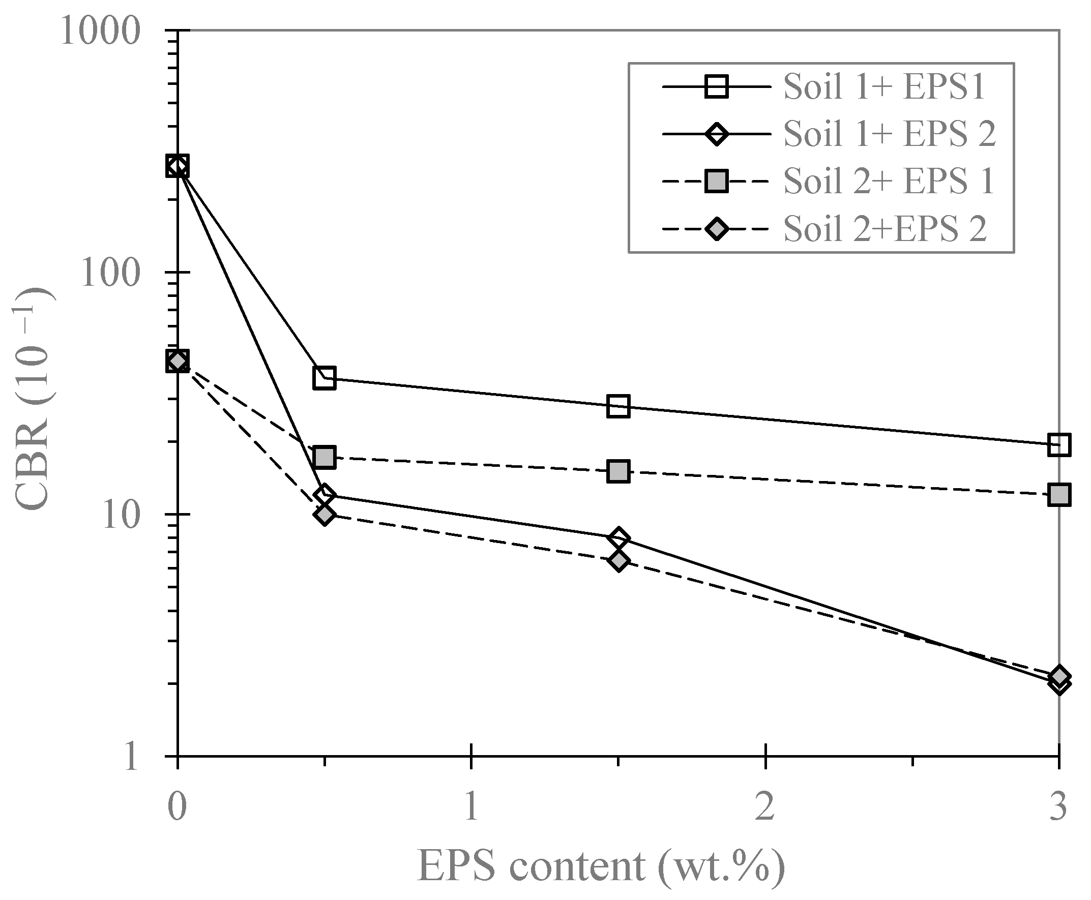
3.2. CBR Results
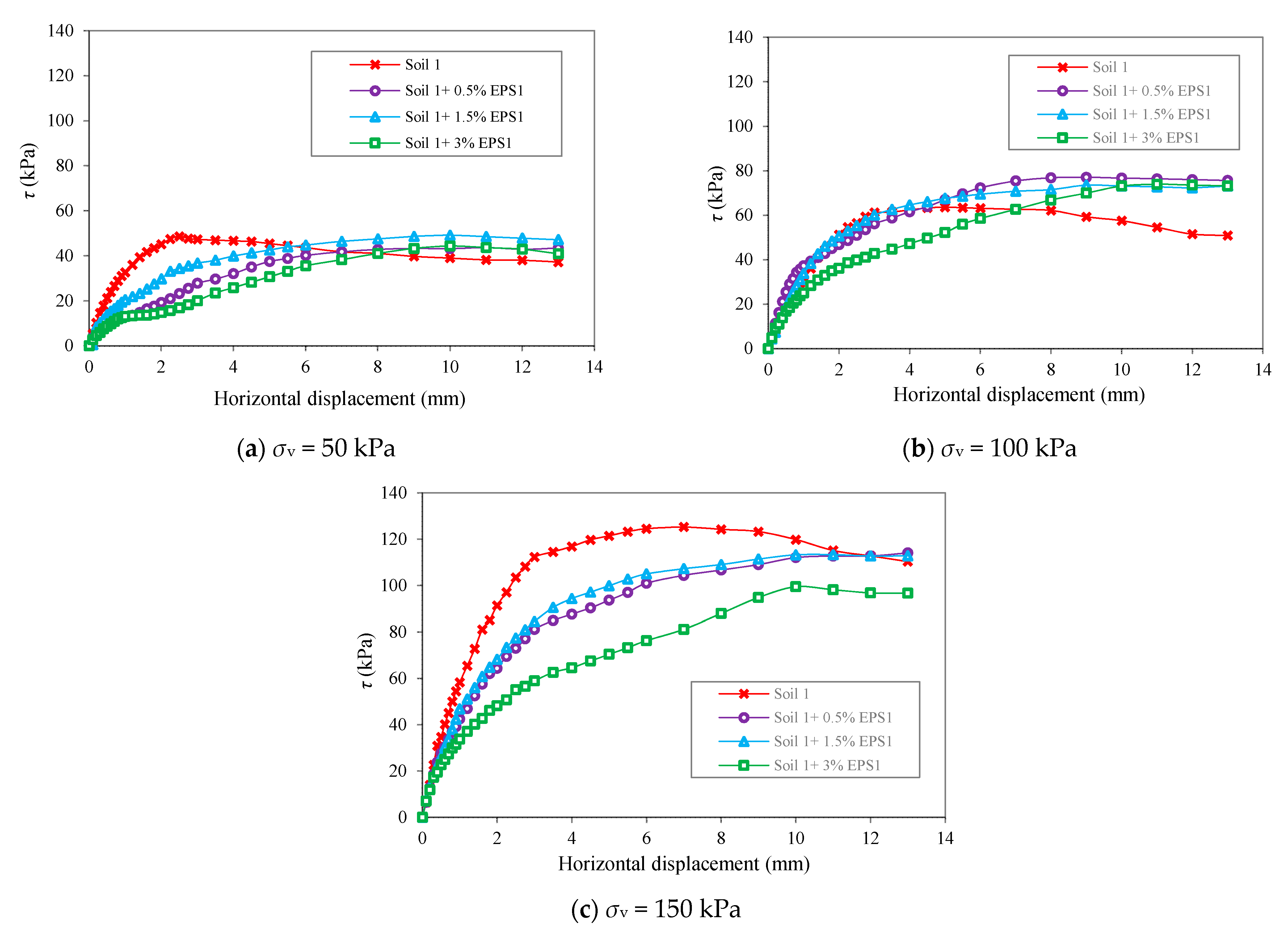
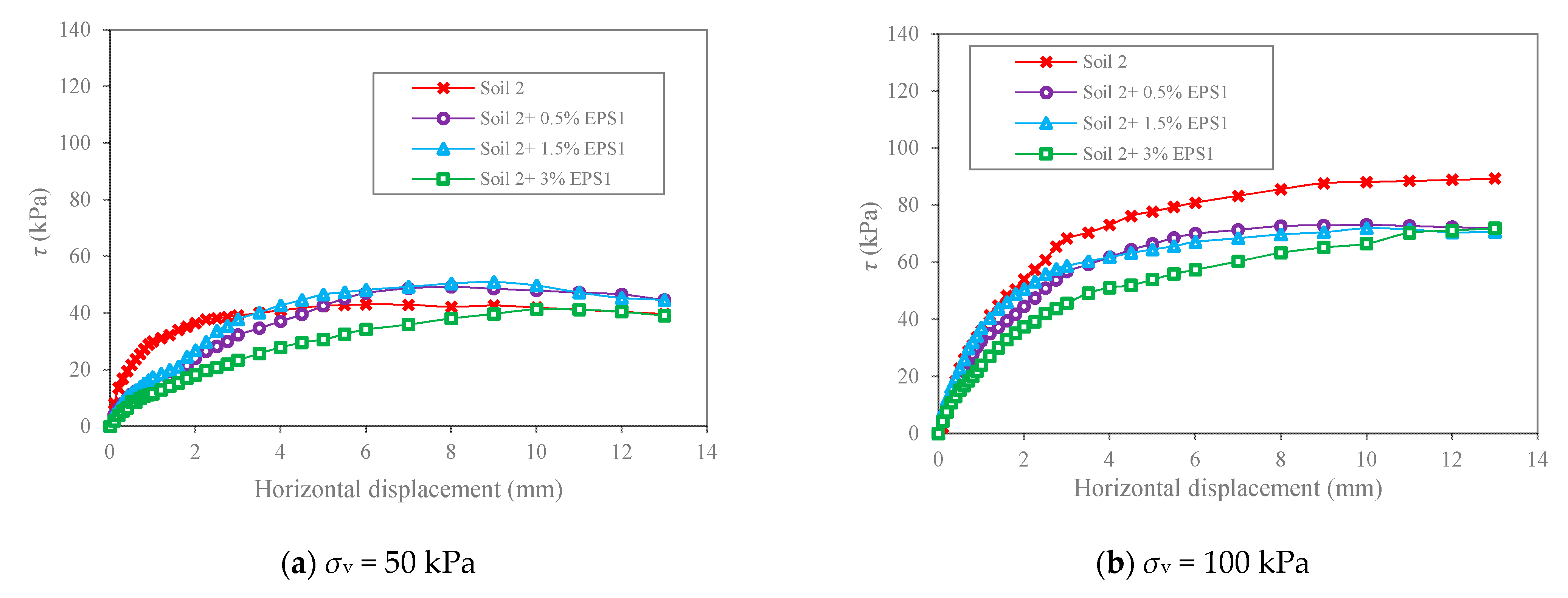
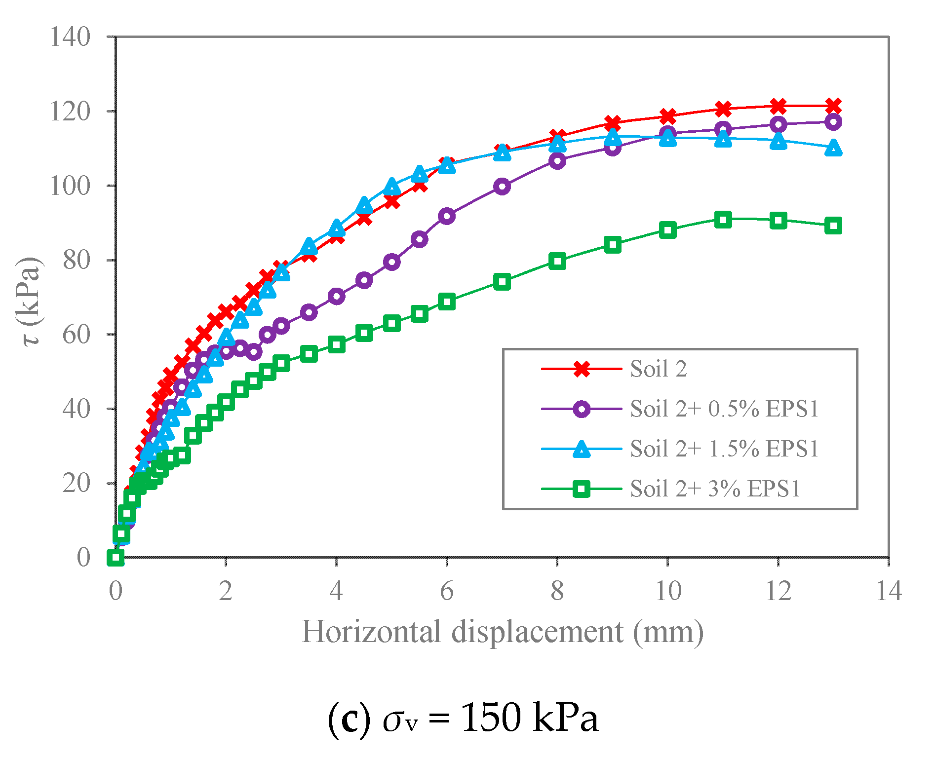
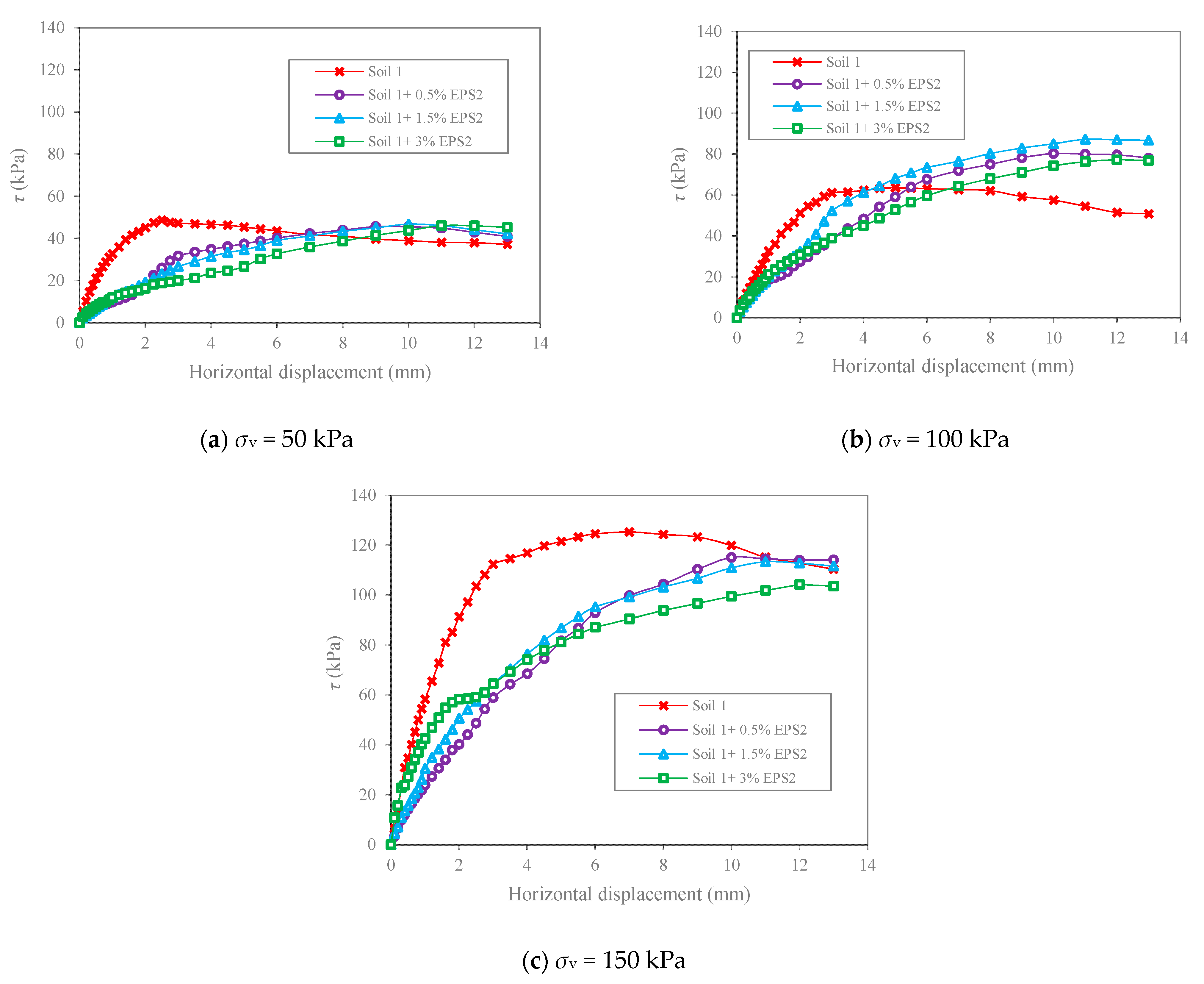
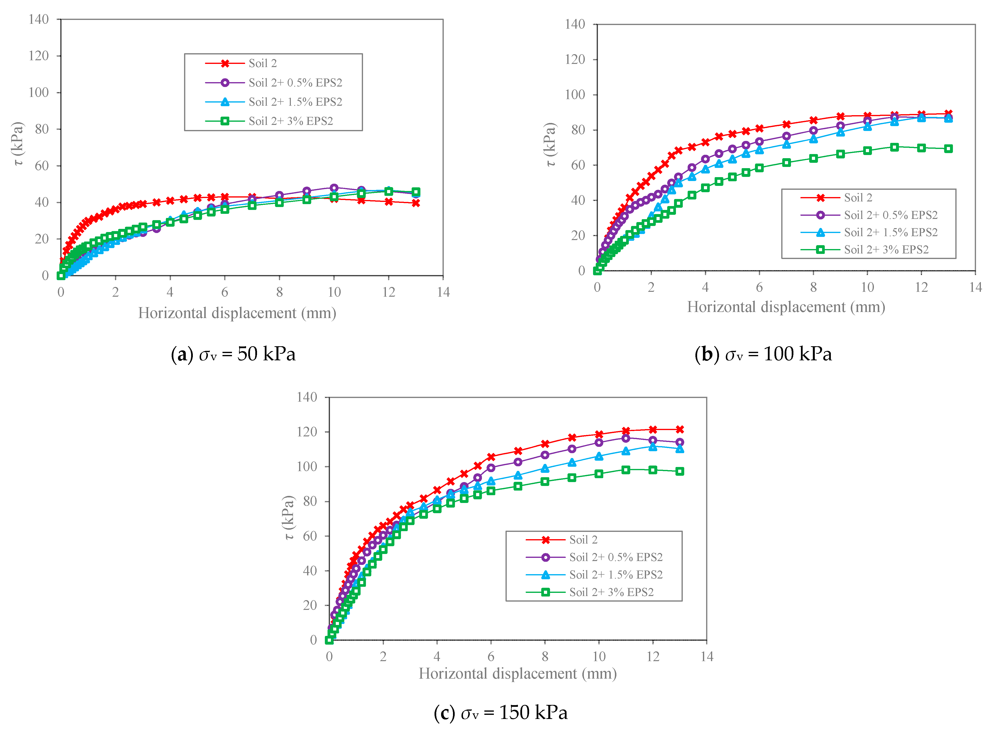
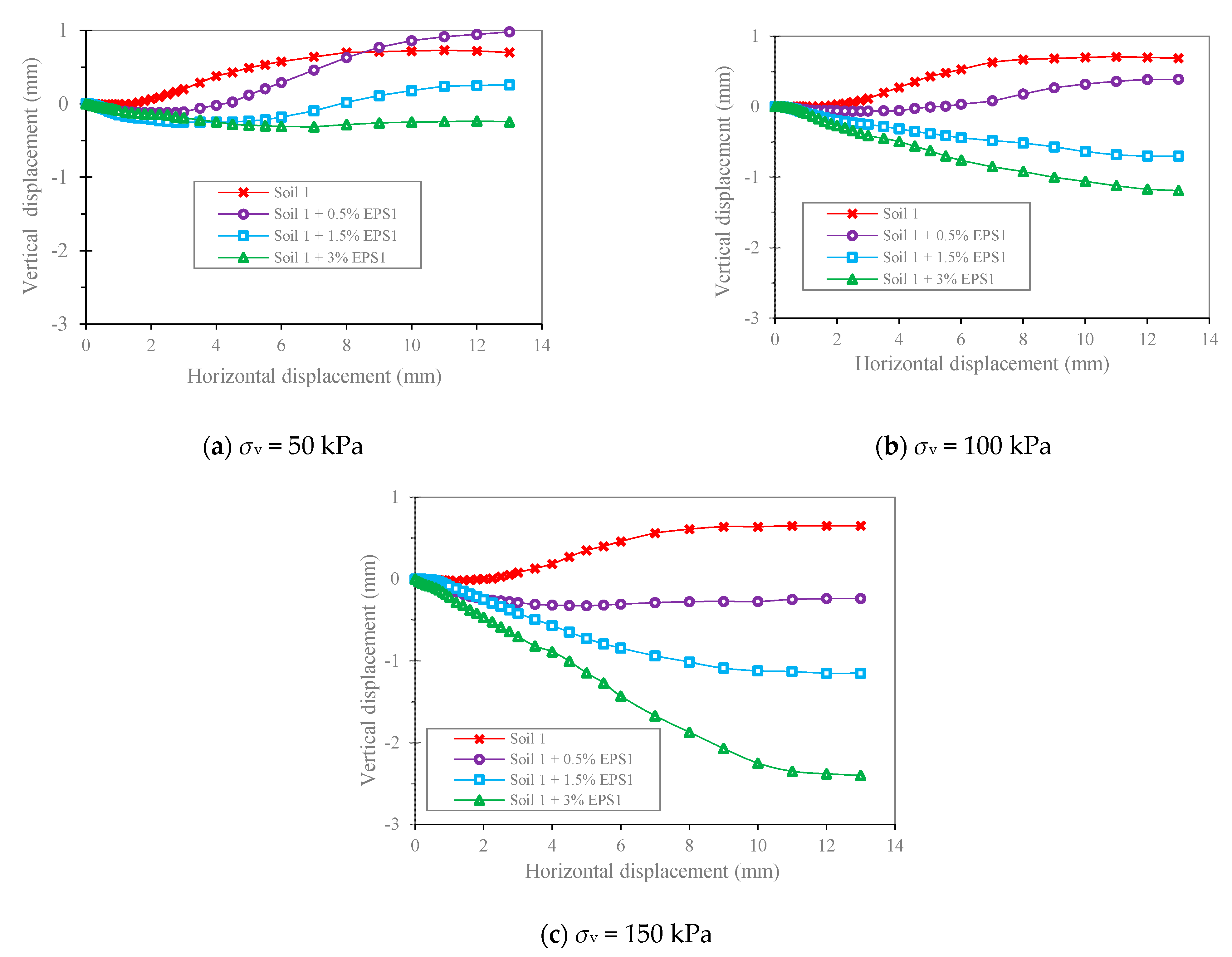
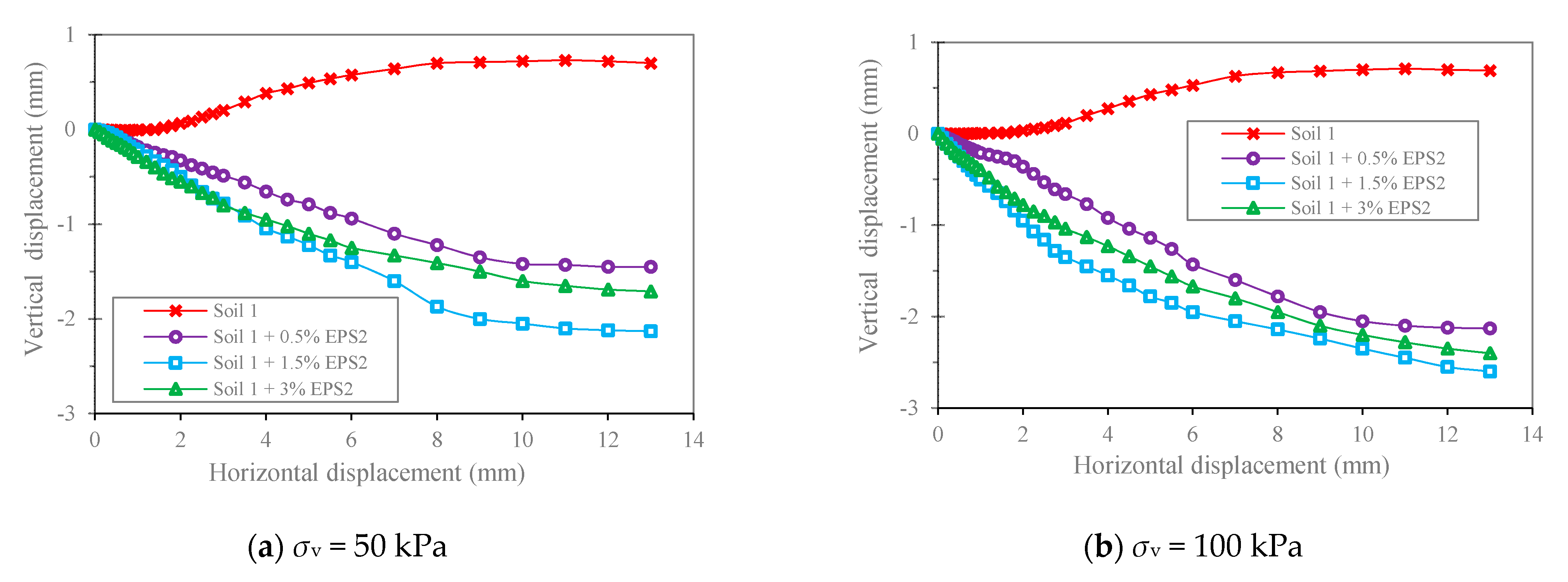
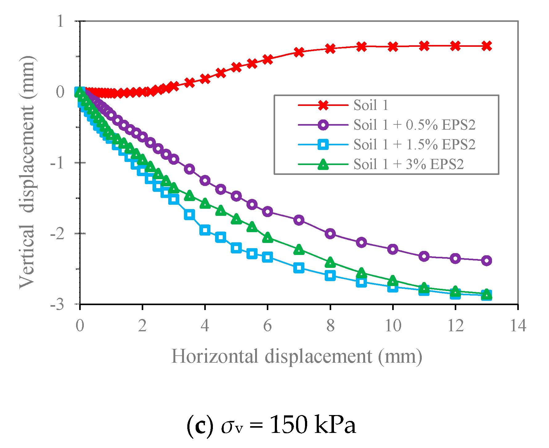
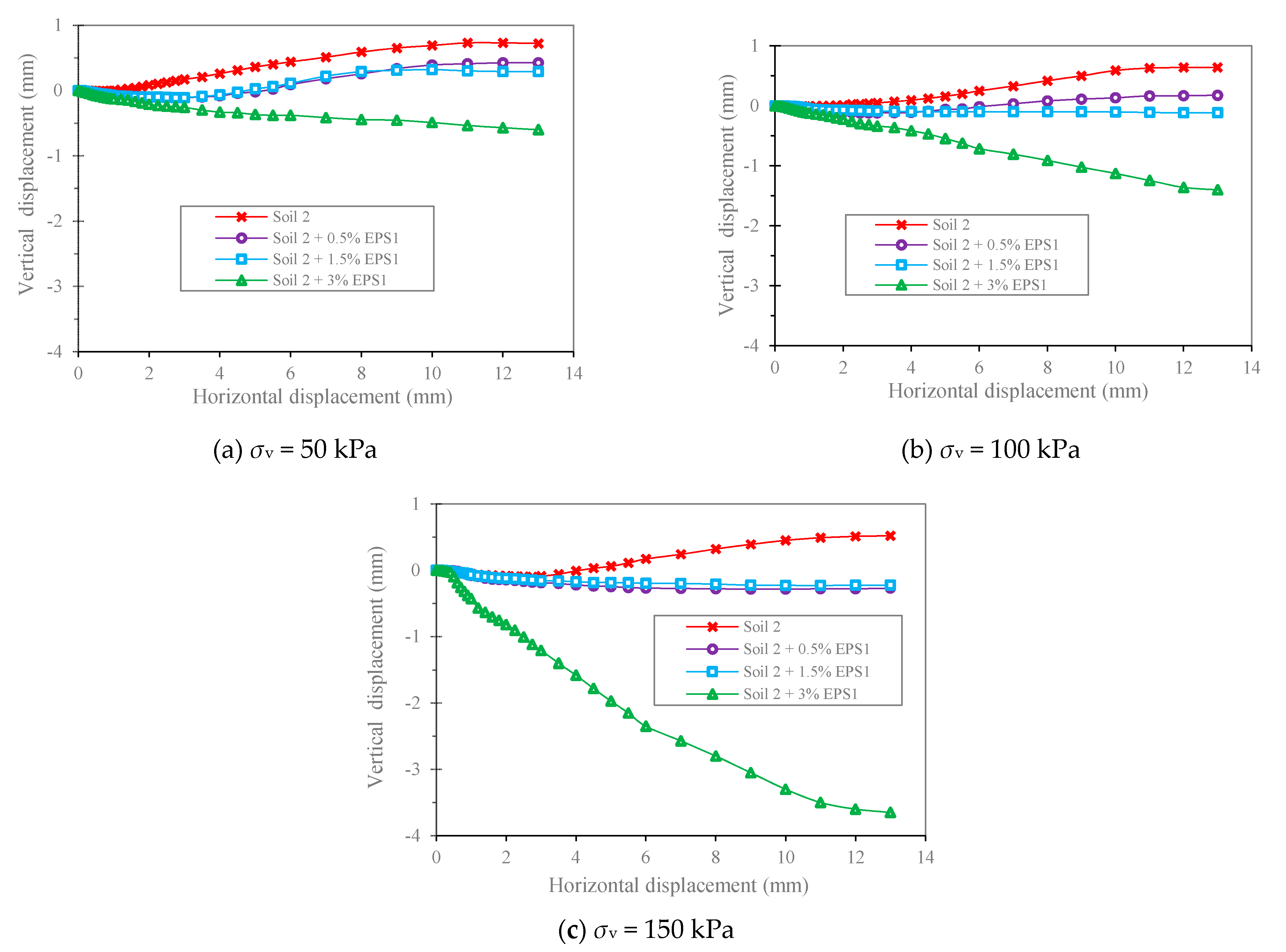
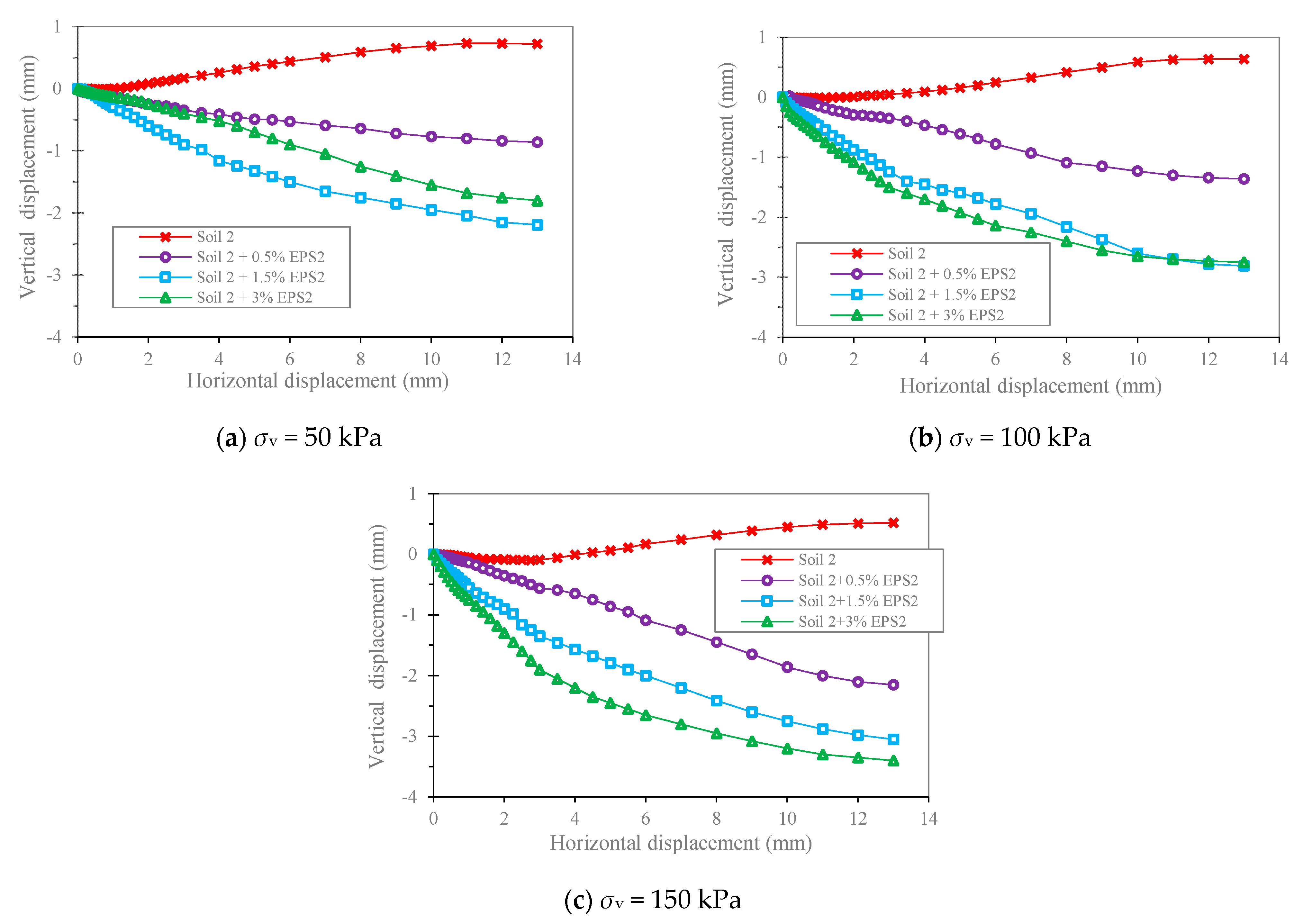
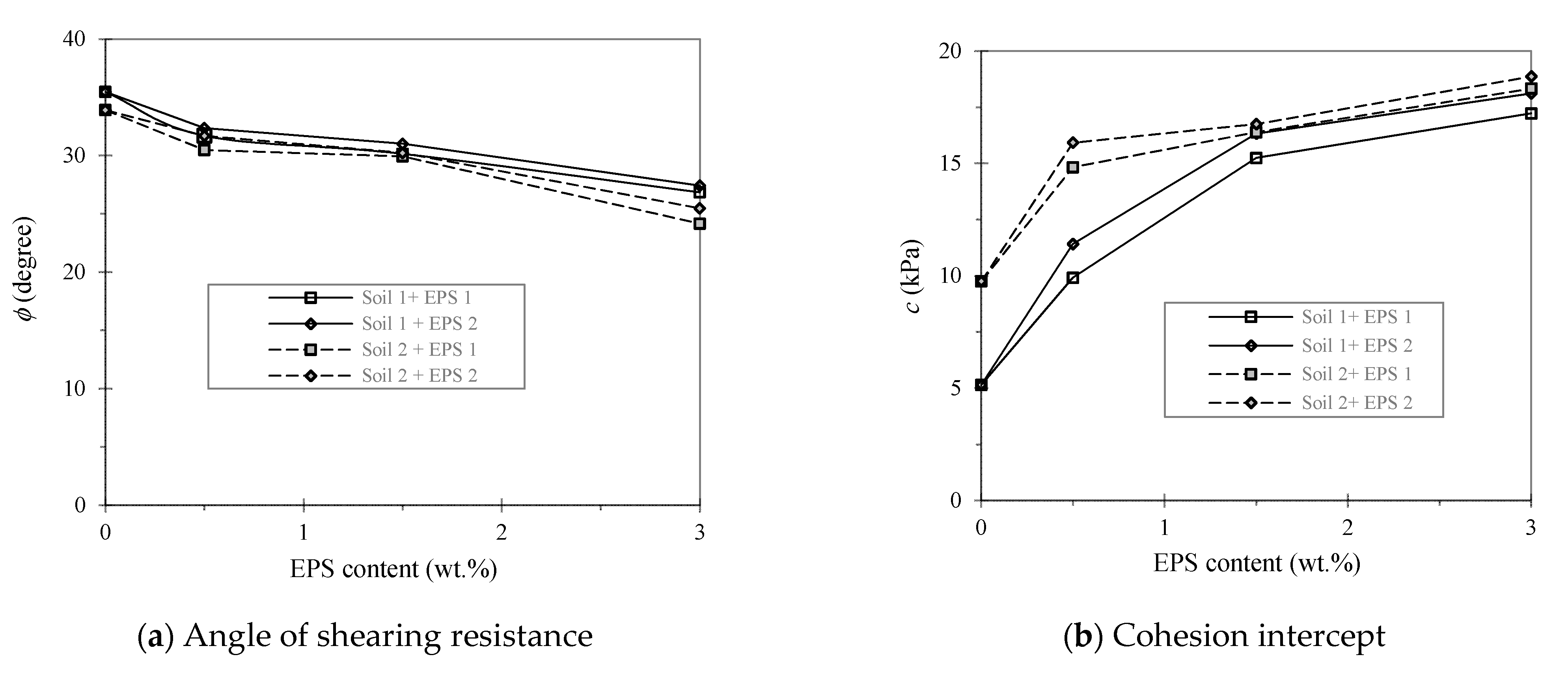
3.3. Direct Shear Results
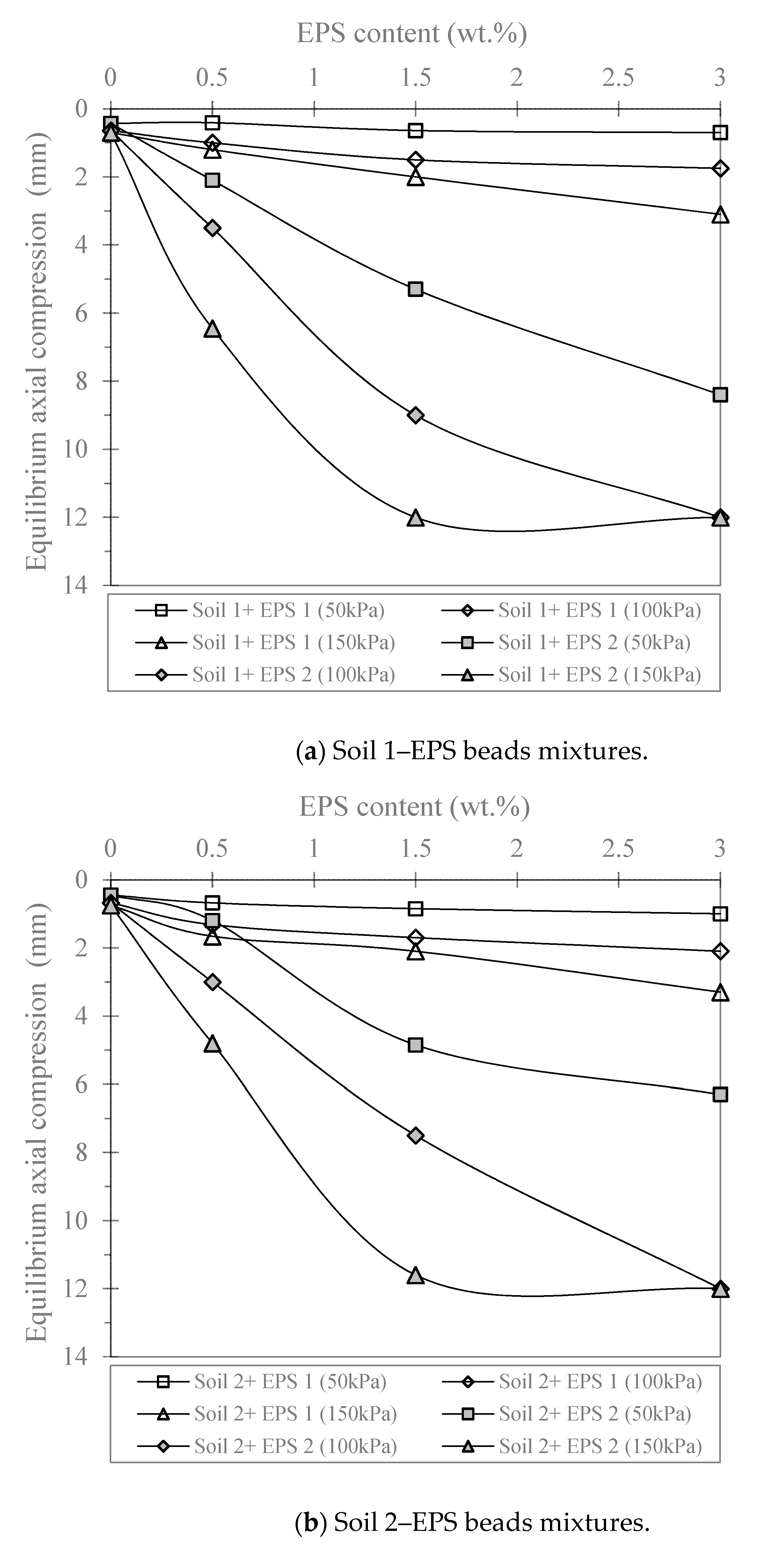
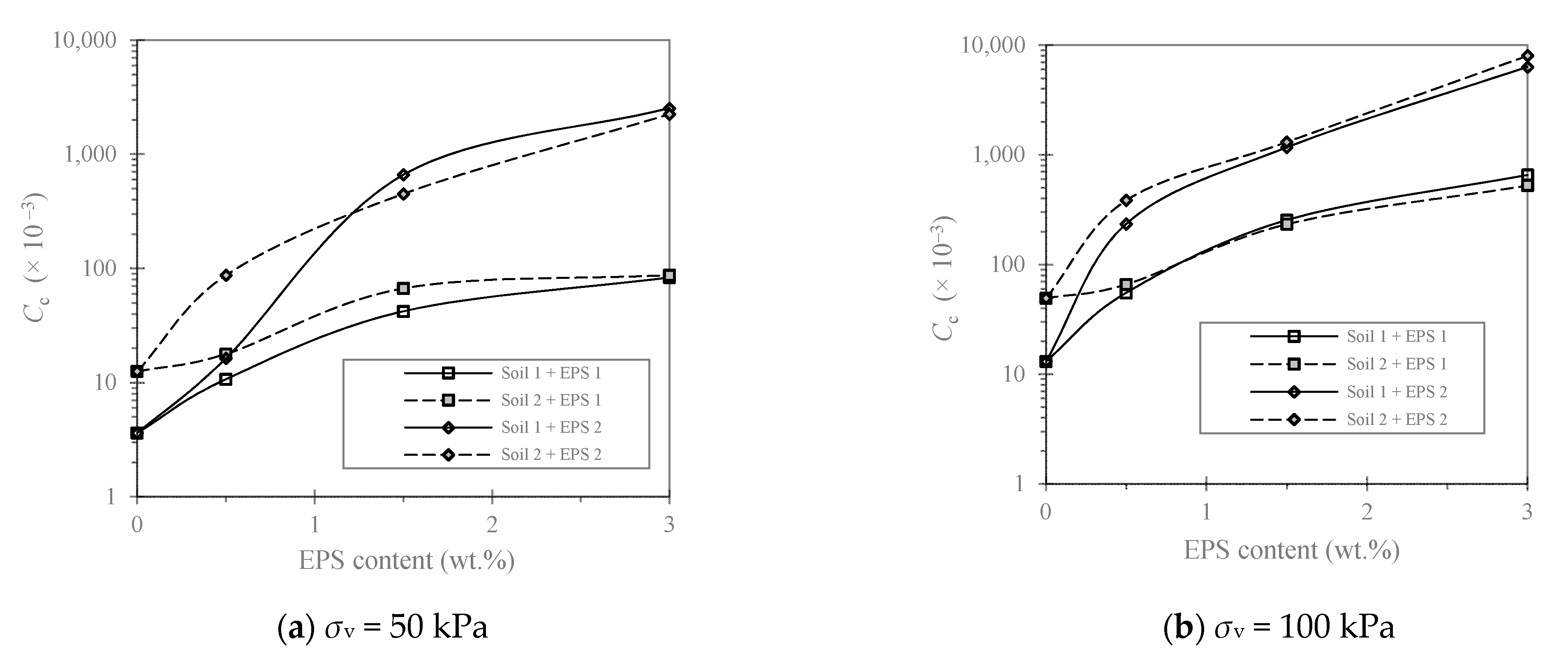
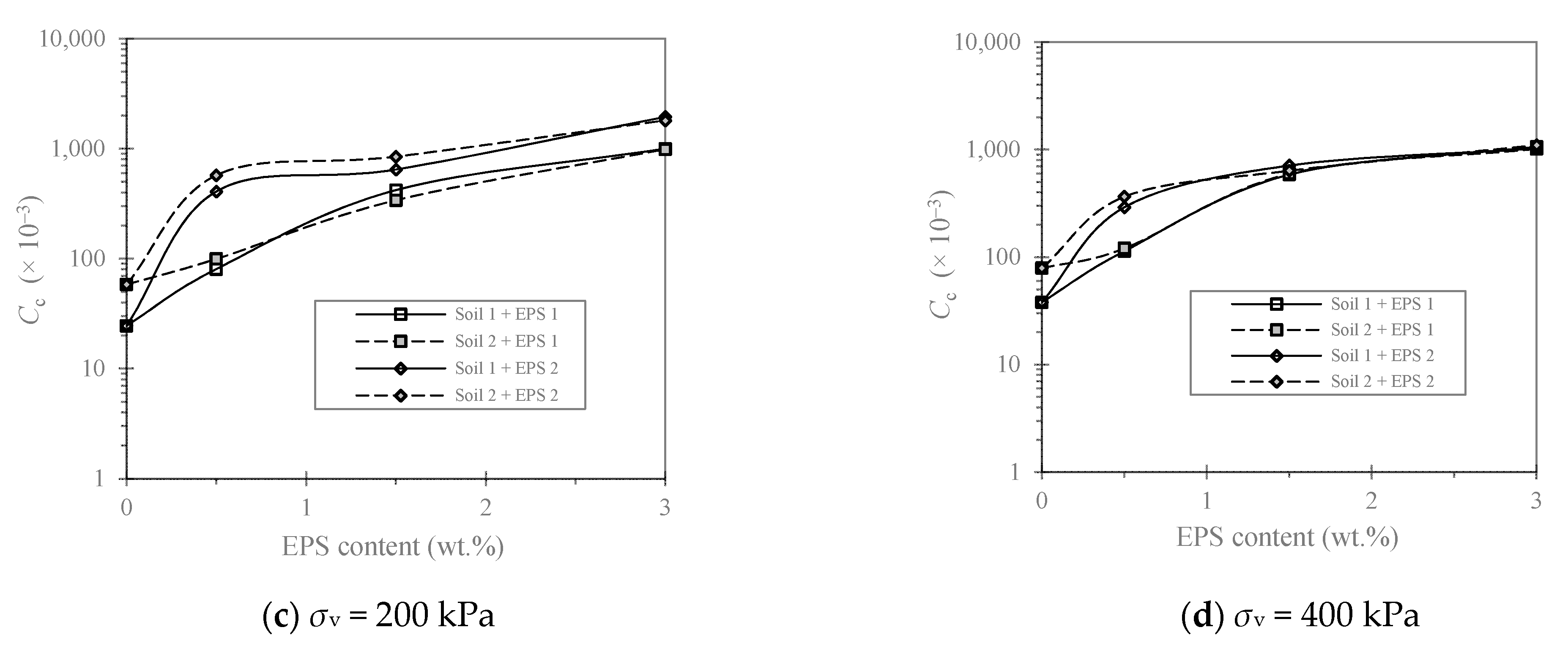
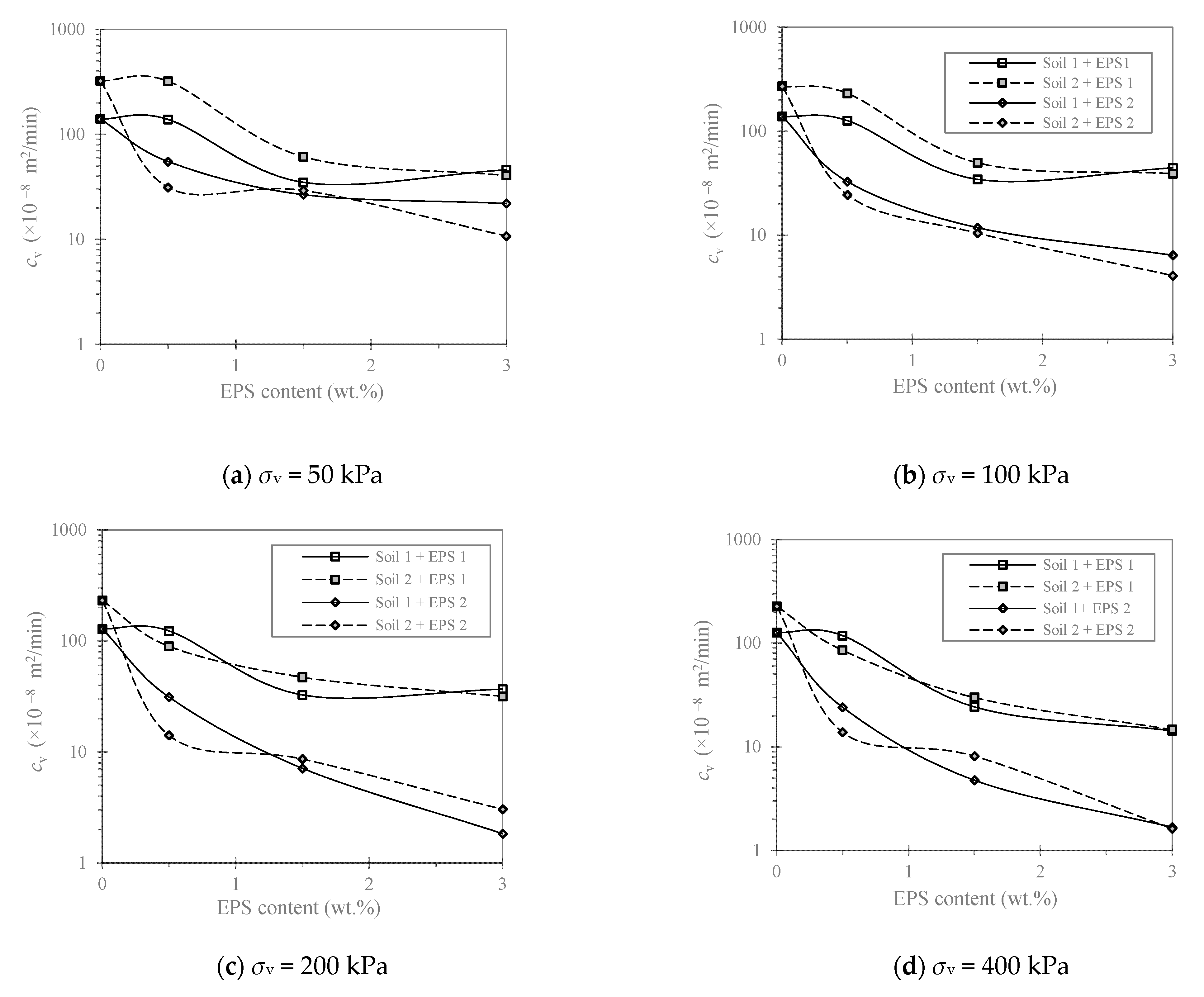
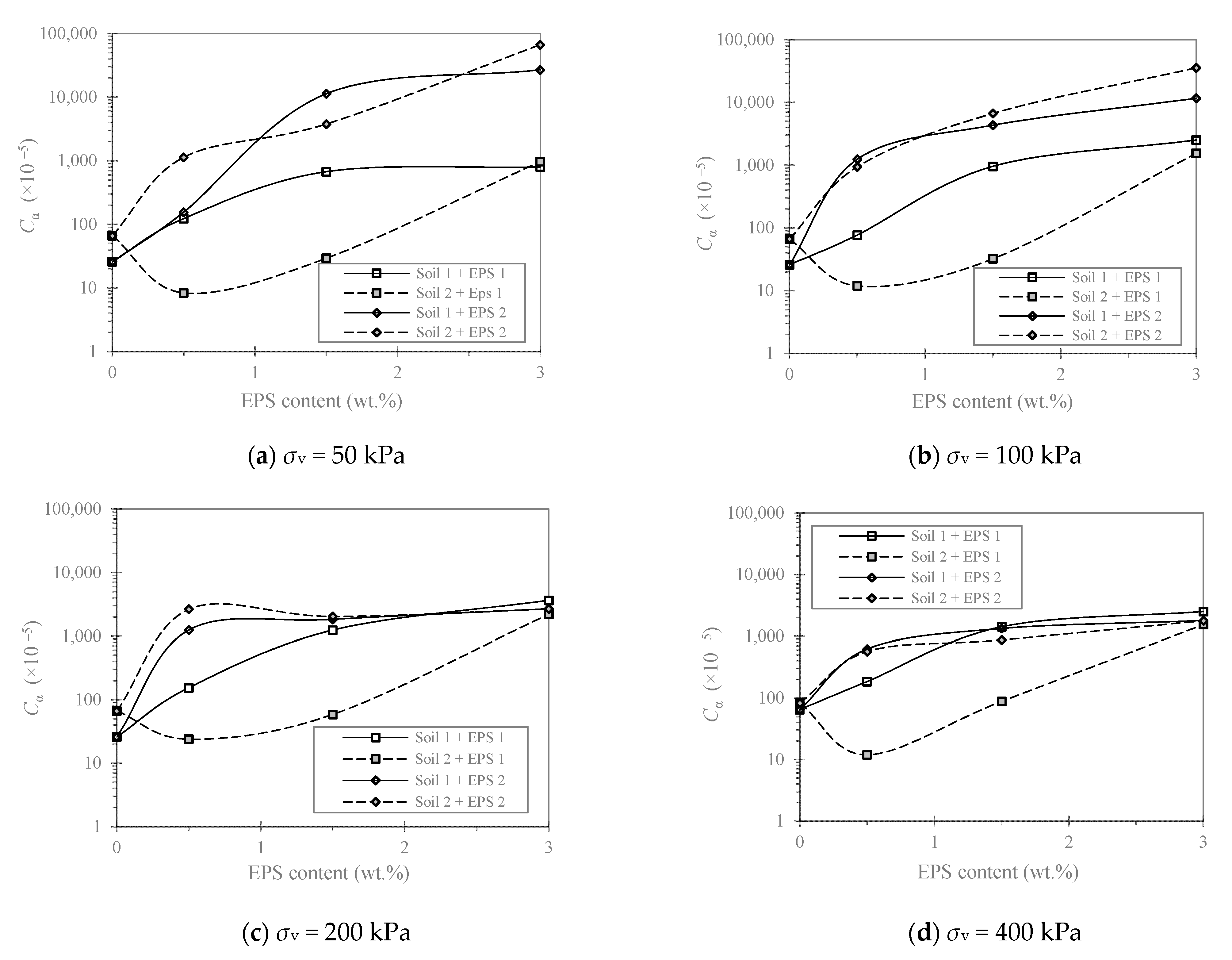
3.4. Oedometer Results
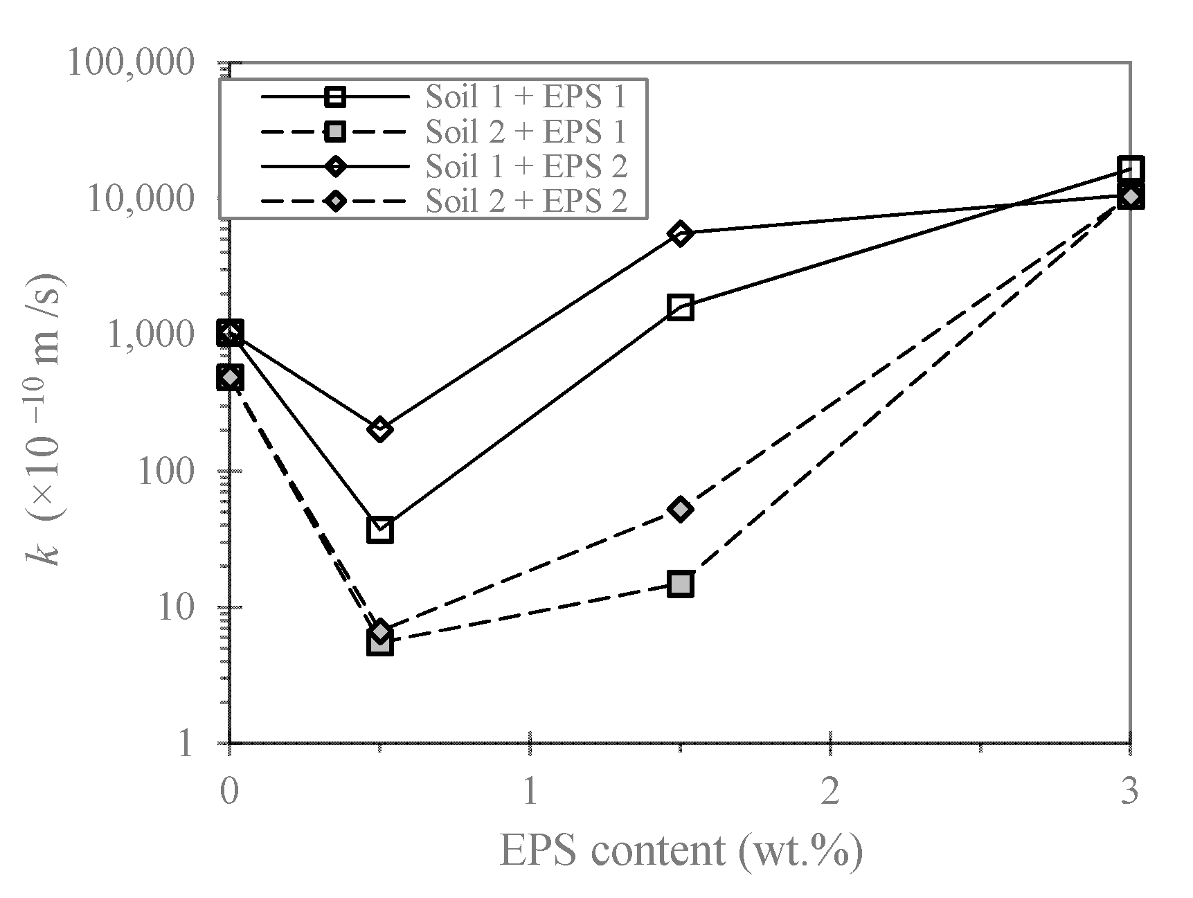
3.5. Permeability Results
4. Environmental Concerns
5. Summary and Conclusions
Author Contributions
Funding
Conflicts of Interest
Nomenclature
| c | cohesion intercept |
| Cc | compression index |
| CU | uniformity coefficient |
| cv | coefficient of consolidation |
| CZ | curvature coefficient |
| Cα | secondary compression index |
| D10 | 10% of soil particles finer than this size |
| D30 | 30% of soil particles finer than this size |
| D50 | mean particle size |
| D60 | 60% of soil particles finer than this size |
| Gs(EPS) | specific gravity of EPS beads |
| Gs | specific gravity of soil solids |
| k | permeability coefficient |
| w | water content |
| ρd | dry density |
| ρdmax | maximum compacted dry density |
| γdmax | maximum dry unit weight |
| γdmin | minimum dry unit weight |
| η | weight percentage of EPS in dry soil–EPS beads mixture |
| φ | angle of shearing resistance |
| σv | applied normal stress |
| τ | shear resistance |
| τf | peak shear resistance |
| χ | volume percentage of EPS in dry soil–EPS beads mixture |
References
- Oh, S.W.; Lee, J.K.; Kwon, Y.C.; Lee, B.J. Bearing Capacity of Light Weight Soil Using Recycled Styrofoam Beads. In Proceedings of the 12th International Offshore and Polar Engineering Conference, Kitakyushu, Japan, 26–31 May 2002; International Society of Offshore and Polar Engineers: Cupertino, CA, USA, 2002; pp. 670–674. [Google Scholar]
- Tsuchida, T.; Kang, M.S. Use of Lightweight Treated Soil Method in Seaport and Airport Construction Projects. In Proceedings of the Nakase Memorial Symposium on Soft Ground Engineering in Coastal Areas, Yokosuka, Japan, 28 November 2002; Tsuchida, T., Watabe, Y., Kang, M.S., Kusakabe, O., Terashi, M., Eds.; Bakelma: Lisse, The Netherlands, 2003; pp. 353–365. [Google Scholar]
- Gan, C.H.; Tan, S.M. Some Construction Experiences on Soft Soil Using Light Weight Materials. In Proceedings of the 2nd International Conference on Advances in Soft Soil Engineering and Technology, Putrajaya, Malaysia, 2–4 July 2003; Universiti Putra Malaysia Press: Serdang Selangor Darul Ehsan, Malaysia, 2003; pp. 609–616. [Google Scholar]
- Tsuchida, T.; Egashira, K. The Lightweight Treated Soil Method—New Geomaterials for Soft Ground Engineering in Coastal Areas; Balkema: Liden, The Netherlands, 2004. [Google Scholar]
- Aabøe, R.; Frydenlund, T.E. 40 Years of Experience with the Use of EPS Geofoam Blocks in Road Construction. In Proceedings of the 4th International Conference Geofoam Blocks in Construction Applications (EPS 2011), Lillestrøm, Norway, 6–8 June 2011. [Google Scholar]
- Stark, T.D.; Arellano, D.; Horvath, J.S.; Leshchinsky, D. Geofoam Applications in the Design and Construction of Highway Embankments; NCHRP Web Document 65 (Project 24-11); Transportation Research Board: Washington, DC, USA, 2004. [Google Scholar]
- Soltani, A.; Deng, A.; Taheri, A.; O’Kelly, B.C. Engineering reactive clay systems by ground rubber replacement and polyacrylamide treatment. Polymers 2019, 11, 1675. [Google Scholar] [CrossRef] [PubMed] [Green Version]
- Shahrokhi-Shahraki, R.; Kwon, P.S.; Park, J.; O’Kelly, B.C.; Rezania, S. BTEX and heavy metals removal using pulverized waste tires in engineered fill materials. Chemosphere 2020, 242, 125281. [Google Scholar] [CrossRef]
- Soltani, A.; Taheri, A.; Deng, A.; O’Kelly, B.C. Improved geotechnical behavior of an expansive soil amended with tire-derived aggregates having different gradations. Minerals 2020, 10, 923. [Google Scholar] [CrossRef]
- Ghadr, S.; Samadzadeh, A.; Bahadori, H.; O’Kelly, B.C.; Assadi-Langroudi, A. Liquefaction resistance of silty sand with ground rubber additive. Int. J. Geomech. 2021, 21, 04021076. [Google Scholar] [CrossRef]
- Vaslestad, J.; Bartlett, S.F.; Aabøe, R.; Burkart, H.; Ahmed, T.; Arellano, D. Bridge Foundations Supported by EPS Geofoam Embankments on Soft Soil. In Proceedings of the 5th International Conference on Geofoam Blocks in Construction Applications (EPS 2018), Kyrenia, Cyprus, 9–11 May 2018; Arellano, D., Özer, A.T., Bartlett, S.F., Vaslestad, J., Eds.; Springer: Cham, Switzerland, 2019; pp. 281–294. [Google Scholar] [CrossRef]
- Bartlett, S.F.; Lingwall, B.N.; Vaslestad, J. Methods of protecting buried pipelines and culverts in transportation infrastructure using EPS geofoam. Geotext. Geomembr. 2015, 43, 450–461. [Google Scholar] [CrossRef]
- Maleska, T.; Nowacka, J.; Beben, D. Application of EPS geofoam to a soil–steel bridge to reduce seismic excitations. Geosciences 2019, 9, 448. [Google Scholar] [CrossRef] [Green Version]
- Abdullah, M.; Huat, B.B.K.; Kamaruddin, R.; Ali, A.K.; Duraisamy, Y. Design and performance of EPS footing for lightweight farm structure on peat soil. Am. J. Appl. Sci. 2007, 4, 484–490. [Google Scholar] [CrossRef] [Green Version]
- Aminu, I.; Asadi, A.; O’Kelly, B.C.; Huat, B.B.K.; Reul, O. Ultralightweight foundation system for peaty ground. Environ. Geotech. 2021. [Google Scholar] [CrossRef]
- Deng, A.; Xiao, Y. Measuring and modeling proportion-dependent stress–strain behavior of EPS-sand mixture. Int. J. Geomech. 2010, 10, 214–222. [Google Scholar] [CrossRef] [Green Version]
- Edinçliler, A.; Özer, A.T. Effects of EPS bead inclusions on stress–strain behaviour of sand. Geosynth. Int. 2014, 21, 89–102. [Google Scholar] [CrossRef]
- Liu, H.L.; Deng, A.; Chu, J. Effect of different mixing ratios of polystyrene pre-puff beads and cement on the mechanical behaviour of lightweight fill. Geotext. Geomembr. 2006, 24, 331–338. [Google Scholar] [CrossRef]
- Satoh, T.; Tsuchida, T.; Mitsukuri, K.; Hong, Z. Field placing test of lightweight treated soil under seawater in Kumamoto port. Soils Found. 2001, 41, 145–154. [Google Scholar] [CrossRef] [Green Version]
- Tsuchida, T.; Porbaha, A.; Yamane, N. Development of a geomaterial from dredged bay mud. J. Mater. Civ. Eng. 2001, 13, 152–160. [Google Scholar] [CrossRef]
- Yoonz, G.L.; Jeon, S.S.; Kim, B.T. Mechanical characteristics of light-weighted soils using dredged materials. Mar. Georesource Geotechnol. 2004, 22, 215–229. [Google Scholar] [CrossRef]
- Rocco, N.T. Characterization of Expanded Polystyrene (EPS) and Cohesive Soil Mixtures. Ph.D. Thesis, Missouri University of Science and Technology, Rolla, MI, USA, 2012. [Google Scholar]
- ASTM C128. Standard Test Method for Relative Density (Specific Gravity) and Absorption of Fine Aggregate; ASTM International: West Conshohocken, PA, USA, 2015. [Google Scholar]
- ASTM D698. Standard Test Methods for Laboratory Compaction Characteristics of Soil Using Standard Effort (12,400 ft-lbf/ft3 (600 kN-m/m3)); ASTM International: West Conshohocken, PA, USA, 2012. [Google Scholar]
- ASTM D1883. Standard Test Methods for CBR (California Bearing Ratio) of Laboratory-Compacted Soils; ASTM International: West Conshohocken, PA, USA, 2016. [Google Scholar]
- ASTM D3080. Standard Test Methods for Direct Shear Test of Soils under Consolidated-Drained Conditions; ASTM International: West Conshohocken, PA, USA, 2001. [Google Scholar]
- ASTM D2435. Standard Test Method for One-Dimensional Consolidation Properties of Soils Using Incremental Loading; ASTM International: West Conshohocken, PA, USA, 2001. [Google Scholar]
- Thompson, R.C.; Olsen, Y.; Mitchell, R.P.; Davis, A.; Rowland, S.J.; John, A.W.G.; McGonigle, D.; Russell, A.E. Lost at sea: Where is all the plastic? Science 2004, 304, 838. [Google Scholar] [CrossRef]
- Galgani, F.; Hanke, G.; Werner, S.; De Vrees, L. Marine litter within the European Marine Strategy Framework Directive. ICES J. Mar. Sci. 2013, 70, 1055–1064. [Google Scholar] [CrossRef]
- O’Kelly, B.C.; El-Zein, A.; Liu, X.; Patel, A.; Fei, X.; Sharma, S.; Mohammad, A.; Goli, V.S.N.S.; Wang, J.J.; Li, D.; et al. Microplastics in soils: An environmental geotechnics perspective. Environ. Geotech. 2021. [Google Scholar] [CrossRef]
- Qi, R.; Jones, D.L.; Li, Z.; Liu, Q.; Yan, C. Behavior of microplastics and plastic film residues in the soil environment: A critical review. Sci. Total Environ. 2020, 703, 134722. [Google Scholar] [CrossRef] [PubMed]
- Van Praagh, M.; Hartman, C.; Brandmyr, E. Microplastics in Landfill Leachates in the Nordic Countries; TemaNord NV-2018:557; Nordisk Ministerråd: Copenhagen, Denmark, 2018. [Google Scholar] [CrossRef]
- Kiyama, Y.; Miyahara, K.; Ohshima, Y. Active uptake of artificial particles in the nematode Caenorhabditis Elegans. J Exp. Biol. 2012, 215, 1178–1183. [Google Scholar] [CrossRef] [Green Version]
- Von Moos, N.; Burkhardt-Holm, P.; Köhler, A. Uptake and effects of microplastics on cells and tissue of the blue mussel Mytilus edulis L. after an experimental exposure. Environ. Sci. Technol. 2012, 46, 11327–11335. [Google Scholar] [CrossRef]
- Farrell, P.; Nelson, K. Trophic level transfer of microplastic: Mytilus edulis (L.) to Carcinus maenas (L.). Environ. Pollut. 2013, 177, 1–3. [Google Scholar] [CrossRef]
- Wright, S.L.; Rowe, D.; Thompson, R.C.; Galloway, T.S. Microplastic ingestion decreases energy reserves in marine worms. Curr. Biol. 2013, 23, 1031–1033. [Google Scholar] [CrossRef] [PubMed] [Green Version]
- Wright, S.L.; Thompson, R.C.; Galloway, T.S. The physical impacts of microplastics on marine organisms: A review. Environ. Pollut. 2013, 178, 483–492. [Google Scholar] [CrossRef] [PubMed]
- Gaylor, M.O.; Harvey, E.; Hale, R.C. Polybrominated diphenyl ether (PBDE) accumulation by earthworms (Eisenia fetida) exposed tobiosolids-, polyurethane foam microparticle-, and Penta-BDE-amended soils. Environ. Sci. Technol. 2013, 47, 13831–13839. [Google Scholar] [CrossRef] [PubMed]
- Hodson, M.E.; Duffus-Hodson, C.A.; Clark, A.; Prendergast-Miller, M.T.; Thorpe, K.L. Plastic bag derived-microplastics as a vector for metal exposure in terrestrial invertebrates. Environ. Sci. Technol. 2017, 51, 4714–4721. [Google Scholar] [CrossRef] [PubMed] [Green Version]
- Cao, D.; Wang, X.; Luo, X.; Liu, G.; Zheng, H. Effects of polystyrene microplastics on the fitness of earthworms in an agricultural soil. IOP Conf. Ser. Earth Environ. Sci. 2017, 61, 012148. [Google Scholar] [CrossRef]
- de Souza Machado, A.A.; Lau, C.W.; Kloas, W.; Bergmann, J.; Bachelier, J.B.; Faltin, E.; Becker, R.; Görlich, A.S.; Rillig, M.C. Microplastics can change soil properties and affect plant performance. Environ. Sci. Technol. 2019, 53, 6044–6052. [Google Scholar] [CrossRef] [Green Version]
- Li, L.; Zhou, Q.; Yin, N.; Tu, C.; Luo, Y. Uptake and accumulation of microplastics in an edible plant. Kexue Tongbao/Chin. Sci. Bull. 2019, 64, 928–934. [Google Scholar] [CrossRef] [Green Version]
- Jiang, X.; Chen, H.; Liao, Y.; Ye, Z.; Li, M.; Klobučar, G. Ecotoxicity and genotoxicity of polystyrene microplastics on higher plant Vicia faba. Environ. Pollut. 2019, 250, 831–838. [Google Scholar] [CrossRef] [PubMed]


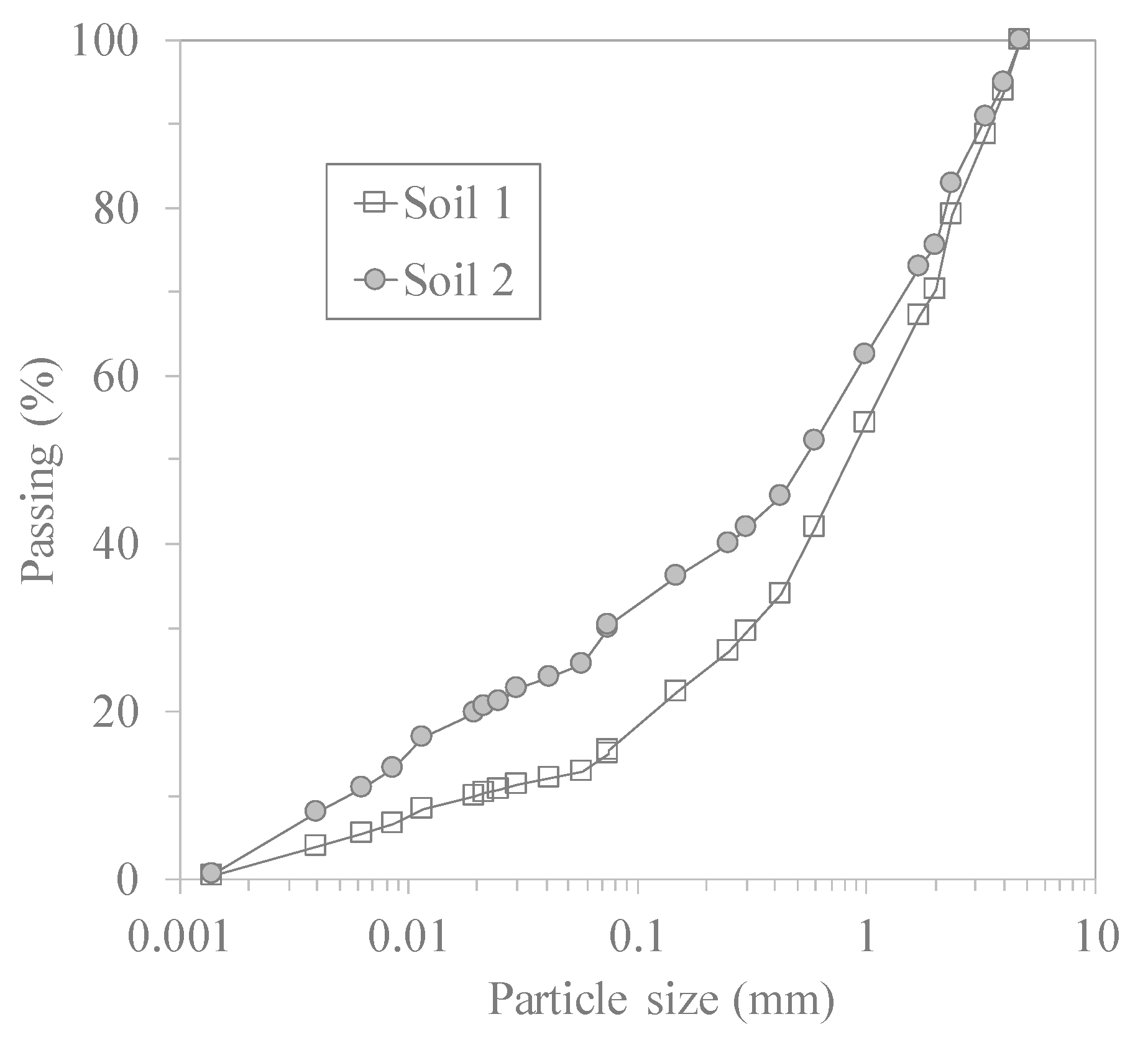
| Material | D10 (mm) | D30 (mm) | D50 (mm) | D60 (mm) | CU | CZ | Gs |
|---|---|---|---|---|---|---|---|
| Soil 1 | 0.020 | 0.31 | 0.52 | 0.90 | 45 | 240 | 2.66 |
| Soil 2 | 0.005 | 0.07 | 0.82 | 1.20 | 5.3 | 0.8 | 2.66 |
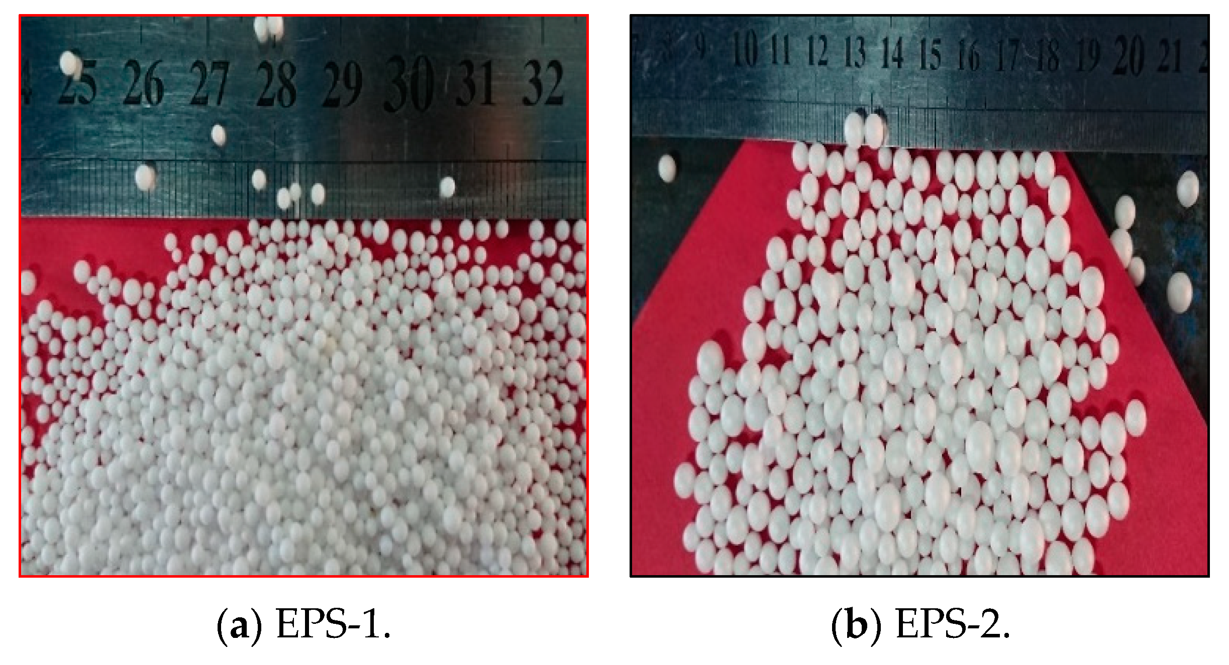
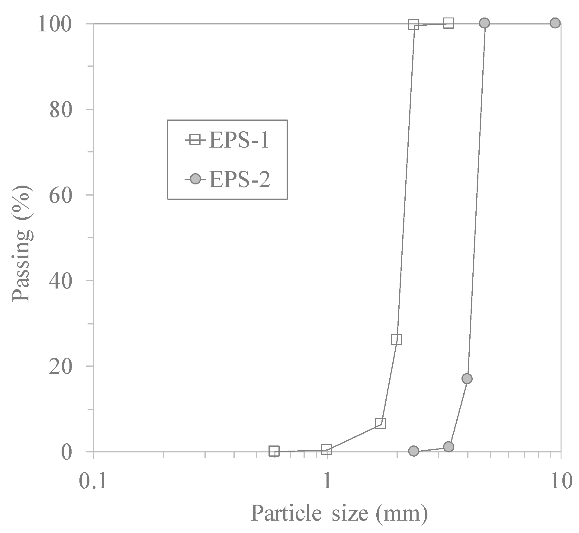
| Material | D10 (mm) | D30 (mm) | D60 (mm) | CU | CZ | Gs(EPS) | γdmin (kN/m3) | γdmax (kN/m3) |
|---|---|---|---|---|---|---|---|---|
| EPS-1 | 1.75 | 2.02 | 2.17 | 1.24 | 1.07 | 0.05 | 0.25 | 0.26 |
| EPS-2 | 3.72 | 4.18 | 4.39 | 1.18 | 1.04 | 0.03 | 0.09 | 0.10 |
| Mixture | EPS (v.%) |
|---|---|
| Soils 1 and 2 with 0.5 wt.% EPS-1 | 21 |
| Soils 1 and 2 with 1.5 wt.% EPS-1 | 44 |
| Soils 1 and 2 with 3.0 wt.% EPS-1 | 61 |
| Soils 1 and 2 with 0.5 wt.% EPS-2 | 31 |
| Soils 1 and 2 with 1.5 wt.% EPS-2 | 57 |
| Soils 1 and 2 with 3.0 wt.% EPS-2 | 73 |
Publisher’s Note: MDPI stays neutral with regard to jurisdictional claims in published maps and institutional affiliations. |
© 2021 by the authors. Licensee MDPI, Basel, Switzerland. This article is an open access article distributed under the terms and conditions of the Creative Commons Attribution (CC BY) license (https://creativecommons.org/licenses/by/4.0/).
Share and Cite
Abbasimaedeh, P.; Ghanbari, A.; O’Kelly, B.C.; Tavanafar, M.; Irdmoosa, K.G. Geomechanical Behaviour of Uncemented Expanded Polystyrene (EPS) Beads–Clayey Soil Mixtures as Lightweight Fill. Geotechnics 2021, 1, 38-58. https://0-doi-org.brum.beds.ac.uk/10.3390/geotechnics1010003
Abbasimaedeh P, Ghanbari A, O’Kelly BC, Tavanafar M, Irdmoosa KG. Geomechanical Behaviour of Uncemented Expanded Polystyrene (EPS) Beads–Clayey Soil Mixtures as Lightweight Fill. Geotechnics. 2021; 1(1):38-58. https://0-doi-org.brum.beds.ac.uk/10.3390/geotechnics1010003
Chicago/Turabian StyleAbbasimaedeh, Pouyan, Ali Ghanbari, Brendan C. O’Kelly, Mohsen Tavanafar, and Kourosh Ghaffari Irdmoosa. 2021. "Geomechanical Behaviour of Uncemented Expanded Polystyrene (EPS) Beads–Clayey Soil Mixtures as Lightweight Fill" Geotechnics 1, no. 1: 38-58. https://0-doi-org.brum.beds.ac.uk/10.3390/geotechnics1010003