
Prefabricated Building Systems—Design and Construction


Faculty of Engineering and Information Technology, The University of Melbourne, Parkville, VIC 3010, Australia
*
Author to whom correspondence should be addressed.
Encyclopedia 2022, 2(1), 70-95; https://0-doi-org.brum.beds.ac.uk/10.3390/encyclopedia2010006
Submission received: 20 November 2021
/
Revised: 17 December 2021
/
Accepted: 28 December 2021
/
Published: 6 January 2022
(This article belongs to the Collection Encyclopedia of Engineering)
Definition
:Modern Methods of Construction with Offsite Manufacturing is an advancement from prefabricated technologies that existed for decades in the construction industry, and is a platform to integrate various disciplines into providing a more holistic solution. Due to the rapid speed of construction, reduced requirement of labour and minimised work on site, offsite manufacturing and prefabricated building systems are becoming more popular, and perhaps a necessity for the future of the global construction industry. The approach to the design and construction of prefab building systems demands a thorough understanding of their unique characteristics.
1. Introduction
A prefabricated (prefab) building, by definition, is where an entire building or an assembly of its components is manufactured at an offsite facility and assembled onsite from self-sustained volumetric modules or separate panels. Prefabrication has existed in construction for many decades in various forms such as dry wall systems, structural insulated panels (SIP), prestressed beams, prefabricated roof trusses, prefabricated reinforcement cages, etc. [1,2,3]. Modern Methods of Construction (MMC) with Offsite Manufacturing (OSM) have arisen to integrate these various technologies into a more holistic and systematic solution, and most modern prefab manufacturers will cater for various architectural designs with prefab units (modules or panels) of creative geometries and innovative connection systems. Such prefab units are mass produced in factories with upskilled specialist workmanship, and at times with automation and robotics in an offsite manufacturing facility, transforming the traditional site-based and labour-intensive approach to construction. Prefab building units have been widely used for residential, commercial and public infrastructure, post-disaster structures and many other applications around the world. Particularly in Australia, the use of modular construction in public infrastructure is a highlight in applications such as railway stations, schools, hospitals, police stations, childcare facilities, etc. [4].
Offsite-manufactured prefabricated building systems are built in three main types of construction, as listed below:
- Modular (volumetric) construction: manufacturing of fully self-contained units in an offsite facility to be transported to site to be assembled to form a complete structure.
- Panelised construction: manufacturing of flat panel units in an offsite facility to be transported to site to be assembled to form a complete structure.
- Hybrid prefab construction (semi-volumetric): combining both panelised and modular methods. Compact modular units (pods) are used for the highly serviced and more repeatable areas such as kitchens and bathrooms, with the remainder of the building constructed using panels or modules.
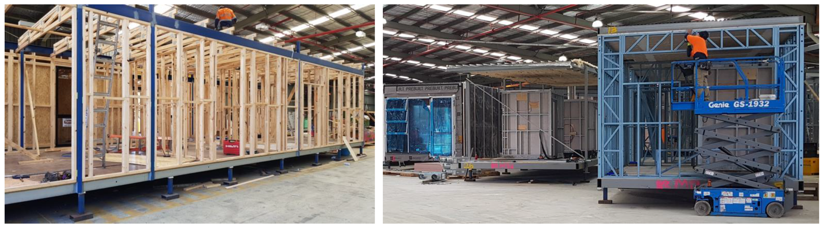
As shown in Figure 1, prefab structures can be built out of steel, timber (including engineered wood products), concrete or a combination of these. The two main benefits of prefab construction are speed of construction and reduced labour compared to traditional methods of construction. Some of the other benefits and features of prefab construction are as follows:
- The reduced need for labour, especially for skilled trades such as welding, enables the construction process to move away from being a labour-oriented operation to a more process-oriented manufacturing and assembly process. This allows construction projects to achieve reduced on-site congestion, waste and pollution.
- The prefab units, especially volumetric modules, can be removed from the main structure for future reuse or relocation. The reusability of prefab units contributes significantly to prefab buildings having a much lower life cycle energy [5].
- Enables construction to commence earlier than usual, as prefab panels or modules can be manufactured in the factory while onsite preparation and foundations works get underway concurrently.
- Prefab construction at present reduces construction time by at least 50% from a site-intensive building [6]. This ensures that the client of the project starts generating revenue much earlier than usual.
- The construction process is significantly less vulnerable to adverse weather, resulting in an even faster construction.
Panelised units are loadbearing in nature, and most of these are integrated with insulation, cladding and internal plasterboards. Structural insulated panels (SIP) are a popular prefabricated panel type in use, especially in countries like Australia. Structural systems of modular buildings are developed using two main types of modules according to their load transfer mechanisms [7], namely:
- 1
- Loadbearing modular structural systems—The perimeter wall structure of the module carries adequate stiffness and continuous connectivity to transfer the gravity loads to the modules below. The roof beams and floor beams are often assisted by stud columns to add stiffness to the walls. This wall stiffness contributes to resistance against racking actions that are experienced during temporary loading scenarios such as moving and handling inside factories, loading and unloading to and from trucks during transportation and during onsite lifting and handling. This system is only feasible for low-rise applications due to the nature of loadbearing systems.
- 2
- Corner-supported modular structural systems—Corner columns in the module take up the floor loads and transfer them to the columns below. This system is also capable of resisting horizontal loads such as earthquake and wind forces—as long as the connections are designed properly, with adequate stiffness, and complying to design standards—thus ideal for multi-storey applications. In most current modular applications, a structural system such as this, with columns and structural connections, is made from steel.
As discussed above, most multi-storey modular buildings found around the world are assemblies of corner-supported modules that are laterally connected to a cast in situ concrete core. This in situ core effectively acts as the primary lateral load resisting element and, in many of these, the floors are poured with concrete after installing the modules. Although these methods are innovative and do save construction time initially, they do not characterise the structures as purely modular nor provide them with the previously mentioned benefits of modular construction. Gunawardena et al. [8] introduced a new concept of an advanced corner-supported structural system, where the shear core of the building could be formed by special modules with infill concrete walls. This would allow a multi-storey building to be constructed using corner-supported modules that could later be dismantled to construct other buildings elsewhere. Since then, similar concepts have realised into prefab structural systems in high-rise modular buildings such as the La Trobe tower in Melbourne, Australia [2].
2. Approach to Structural Design in a DfMA (Design for Manufacturing and Assembly) Format
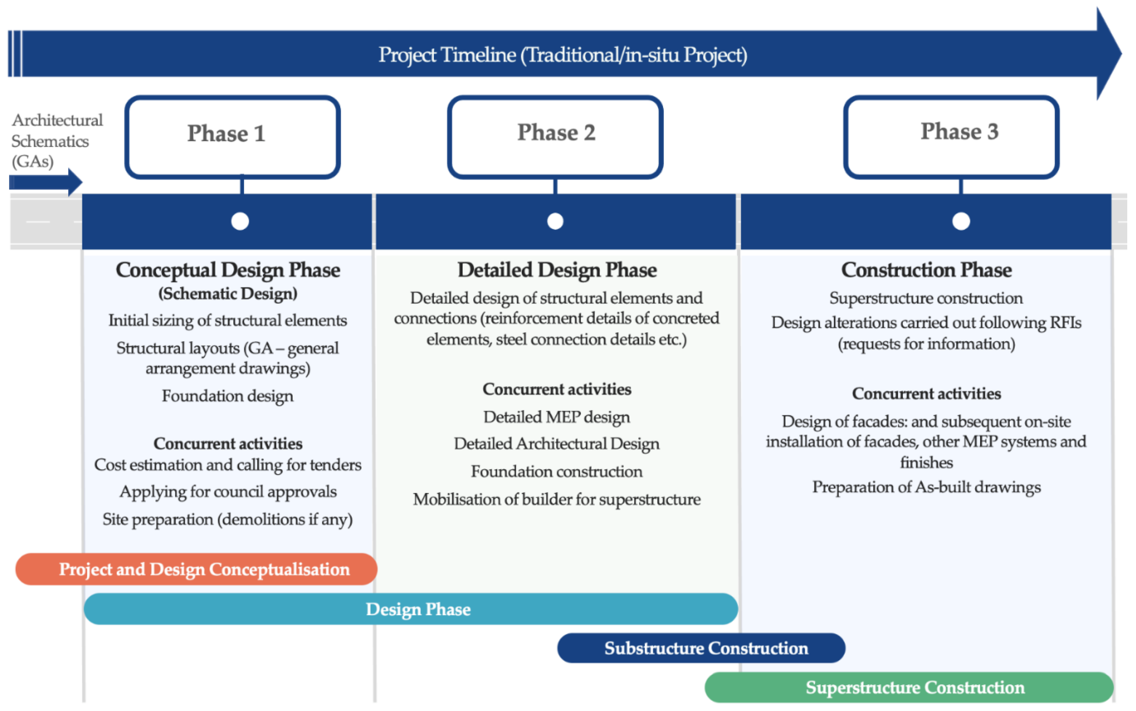
As shown in Figure 2, the design stage of a traditional construction project would follow a path where initially, a conceptual structural design, also known as a schematic design, would be drafted. At this conceptual design phase, the design loads on the structure are determined; locations and arrangement of the structural elements are decided; and preliminary sizing of all structural elements are carried out. This conceptual design would produce structural GAs (general arrangements) that contain a preliminary arrangement and the dimensions of all structural elements with a construction detail of foundations (as foundations need to be constructed first). These schematic designs would be adequate to be produced for approvals from councils (or a similar regulatory body), and even to call for tenders from potential builders. The take-offs for bills of quantities (BOQs) are usually obtained from these schematic GAs using rules of thumb to estimate quantities where no detailed designs are provided (such as the quantities of steel reinforcement). Thereafter, a detailed structural design would be produced, with all the necessary details needed to fully construct the structure (for example, reinforcement details of concrete beams, columns, etc. and connection details of steel and timber structures).
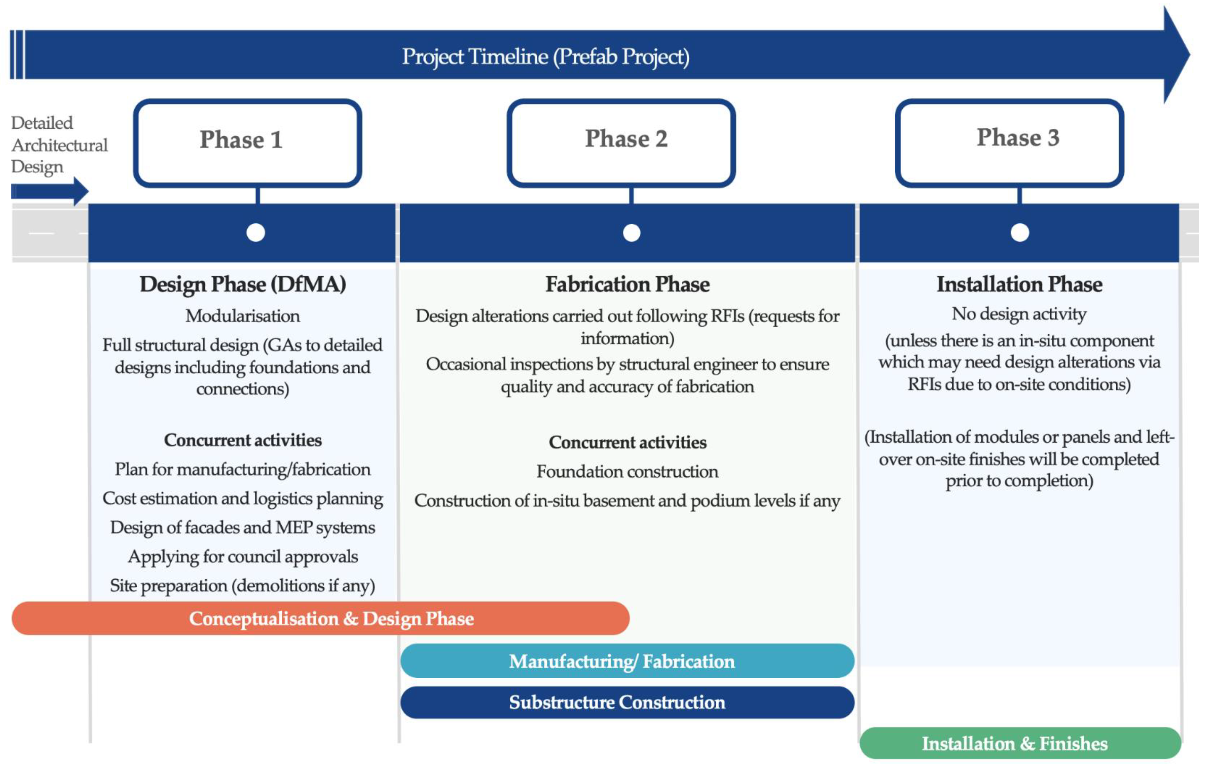
The design process of a prefab building takes a somewhat different and an arguably improved approach (Figure 3). This is mainly due to the necessity of completing the project in a much shorter time and also because the structural design takes place centred around the particular prefab builder, while the specific design task may be subcontracted to an outside structural engineering firm. It is significant how the collaboration of both the builder and the structural engineer is critically important in achieving the design of a prefab building. An efficient structural design of a prefab building will only be achieved with continuous consultation with the builder, and particularly their in-house teams that look after construction logistics and procurement. Mainly, two different types of prefab projects can be identified as they reach the office of a prefab builder or a designer:
- Type A—
- Projects that were conceptualised from the early stages to be built as a prefab building.
- Type B—
- Projects that were initially conceptualised to be built with traditional construction methods (in situ) but are subsequently required to be built using prefab methods.
Out of these, a Type A project would be designed initially by an architect who is quite knowledgeable and experienced in prefab construction methods and would result in a rather smooth process thereafter for the structural designers and the prefab builders. On the contrary, converting a design that was initially conceptualised to be built as an in-situ building (Type B) to then be a prefab building is a rather tedious and at times a very complex activity.
In a nutshell, the design process of an offsite manufactured building has one single design phase (Figure 3), and it takes place centred around the prefab builder (contrary to a traditional design, which is centred around architectural and structural design firms). This design phase, when structured properly, takes the form of a Design for Manufacturing and Assembly (DfMA) format. In this DfMA setup, all relevant faculties of the design, i.e., architectural, structural, MEP and interior designs, are integrated with the necessary detailing and instructions for its in-factory manufacturing, transportation and on-site handling and assembly. A well-organised Building Information Modelling (BIM) framework would ideally integrate of all such specialities. The quantity surveying activity for cost estimation of a traditional construction project gets enriched into a much broader process involving logistics and procurement. Principles of ‘Lean Manufacturing’ have been adopted to incorporate logistics management of both in-factory and on-site work in recent research [9,10] and are gradually being adopted by prefab builders, especially the ones that have a degree of automation within their facilities. Concepts from blockchain and cryptocurrency have also been considered in recent research for developing smart procurement methods and smart contracts to add further efficiencies to prefab building processes [11,12,13].
2.1. Modularisation
Once an architectural concept or a developed design reaches a prefab builder’s office, the first design activity that occurs is the modularisation of the given floor plans. For a rectangular or a similarly simple floor plan, it could be as straightforward as dividing up a given plan into segments, of which the sizes represent the viable modular or panel dimensions. However, every modularisation activity requires the builder to consider a number of key parameters prior to arriving at his viable modular or panel dimensions and their arrangement. Some of these key parameters are listed below:
- 1
- Architectural constraints—The architectural space arrangements will dictate where possible modular splits can be drawn for a modular or flatpack design. Similarly, the locations and dimensions of architectural features such as windows, openings, facades, etc. will dictate where the panel boundaries can be located for a panelised design. A ‘Type A’ design, as discussed previously, will result in a fairly straightforward modularisation process, since an architect who has experience in prefab designs will have prepared architectural general arrangements (GAs) to allow for more efficient modular or panel splits. However, if prefabrication was not envisaged from the beginning (Type B), the splits would need to be carefully drawn around spaces and architectural features, considering how they might impact the rest of the manufacturing, transport, handling and installation processes.
- 2
- Transportation limitations—The capability of the fleet of trucks that a particular prefab builder has access to will dictate the maximum length of a module or panel. While, for example, in Australia, the maximum allowable length for transportation is 30 m (Table 1), most trucks can carry modules and panels up to about 16 m in length. The lane widths of the relevant arterial road network will reflect upon the allowed maximum width for transportation. This may not be a great concern for panels, since they are usually transported vertically. However, for modules, this is one of the main design limitations. A 5 m maximum is allowed in Australia (Table 1), and similar limits apply in other countries as well. Depending on a particular project, other dimensional and weight limits could very possibly apply to the design. Issues such as the condition of access roads, nearby obstructions and other applicable regulations and constraints (for example, heritage structures that cannot be demolished) can impose conditions on the dimensions of prefab units. Similarly, if the prefab units are to be shipped, the volumetric and weight constraints of the vessel will also apply, in addition to the transportation limitations that apply to the embarking and disembarking countries or regions.
- 3
- Lifting and handling limitations—Prefab units need to be designed to dimensions and weights that are practically feasible when it comes to lifting and handling both within the manufacturing facility as well as at the onsite installation. If modules are to be shipped, the lifting and handling limitations at ports will also apply. Depending on the fleet of lifting vehicles such as mobile cranes that are accessible to the prefab builder, and the site access conditions of the particular project site (which dictates the lifting angles and distances), the weight of each module and panel will need to be limited. At least a preliminary understanding of the lifting and handling strategy of a particular project needs to be developed for an efficient modularisation.
- 4
- Onsite installation—The sequence of installation and locations and access to structural connections are important parameters to be considered when dividing up a structure into modules or panels. One of the main intentions of a prefab structure is to reduce the necessity for skilled trades to be on site. Therefore, the onsite installation needs to reduce skilled activities such as welding to a minimum. The connections also need to be safely and conveniently accessible. The arrangement of prefab units needs to be carried out with these in mind.
- 5
- Manufacturing process—The modularisation activity needs to consider the dimensions of various activity stations of the manufacturing plant and its sequence of operations. The prefab units need to move around the facility from one station to the other without the need to restructure any of their geometries and without hindering the normal operations of the factory.
- 6
- Preliminary locations of structural columns and connections—A preliminary idea of the required structural design needs to be considered during the modularisation activity. The location of columns and their structural connections is a critical aspect of efficient modularisation. In contrast to a traditional structural design, the location of structural columns will not only relate to the eventual structure, but also to the structural integrity of a given prefab unit during its transportation, lifting and handling stages, since the lifting connectors should ideally be located on the structural columns.
- 7
- Preliminary locations and dimensions of service spaces (MEP)—A preliminary idea of the required spaces for mechanical, electrical and plumbing (MEP) services such as service ducts and ceilings and heavily serviced areas such as toilets and kitchens need to be known at the modularisation stage. Modular and panel splits will need to be arranged accordingly, and any necessary alterations could be sorted via a well-formed BIM platform or by communicating with the architects and building services engineers.
The abovementioned parameters in a modularisation activity will affect key decision variables that depend on these parameters. Cost and logistical items such as labour and equipment requirements related to the manufacturing process, lifting and handling, transportation and any other part of the project will depend on the outcomes of the modularisation activity.
2.2. Structural Design
As identified in the Australian design standards, and similarly stated in many international codes of practice and guidelines that use a ‘limit state design’ approach, any structural design should comply with three main design criteria, namely:
- 1
- Stability;
- 2
- Serviceability; and
- 3
- Strength.
Structural design standards found elsewhere in the world follow the same principles but may identify these criteria under various different terms (for example, the term ‘Ultimate limit’ is used instead of ‘strength design’ in many standards). None of these would and should change in designing a prefabricated structure. While prefabrication and offsite manufacturing are the methods used to replace traditional construction, the end product is still a building used to serve the same traditional functions. Therefore, the authors, in principle, see no particular need to have separate modular or prefab design standards. However, the authors are quite supportive of modifying the already existing structural design standards to incorporate modular and other prefab construction methods. A good example for such an inclusion of prefab concepts into a traditional design standard is the latest version of the Australian concrete design code, AS3600:2018 [15], where new clauses were added to provide guidelines on minimum levels of strength and safety to prefabricated concrete structures, especially in the design of connections [16].
As previously discussed, the structural design of a prefab project is carried out in one single phase, although the specific tasks related to conceptual design and detailed design are still mostly distinct.
In terms of identifying the loads acting on a given prefab structure, as in any traditional structural design, the usage and importance level need to be determined according to its architectural design and the relevant codes of practice (for example, for structures built in Australia, AS1170.0:2002 [17] provides guidance on choosing importance levels according to their intended purpose and usage, with further guidance on load combinations and return periods (probability of exceedance); AS1170.1:2002 [18] provides guidance on minimum live loads; AS1170.2:2021 [19] provides guidance on minimum wind loads to consider and AS1170.4:2007 [20] provides guidance on minimum earthquake loads to consider).
The selection of most construction materials for facades and other finishes will be decided according to the architectural design. However, the structural design being centred around the prefab builder becomes a significant factor affecting the choice of material for the main structural elements. Depending on the normal practice of the particular prefab builder, the main structural form could be either concrete, timber, steel or a mix of these, and this extends to partition wall frames and the building envelope as well. The decision to go for cold-formed steel frames or softwood frames, or another form, such as SIP (structurally insulated panels), mostly depends on the normal practice of the prefab builder. Having prior knowledge of the finishing materials and their weights adds an extra advantage to the overall structural design, since there would be minimum uncertainty on how heavy some of the finishes and cladding would be (especially since there is minimal opportunity for these choices to be changed later, as the project timeline is very short). The exact values of their weights with a lower factor of safety can be used in determining some of the superimposed dead loads such as cladding, partitions and finishes.
The general arrangement of structural elements will take a different approach to a traditional conceptual structural design. The location of structural columns, especially for a modular building design, would already be decided during the modularisation activity. The floor and roof elements would then be designed within the frame of each module. There could still be many structural components that need to be built in a traditional form, such as foundations, basements, shear walls and podiums, and they would follow the traditional format of design and would usually be built by separate contractors. A panelised building could have even more structural components that need to be built in situ. However, as far as the structural design of the panelised parts is concerned, the design approach would be similar to that of a modular building.
The abovementioned steps of a conceptual structural design of a prefab building are still principally similar to those of a traditional in situ building. However, there are a few further unique steps required for a prefab building design. These unique requirements arise as a result of the structural design being centred around the prefab builder, as discussed previously. Firstly, similar to the modularisation activity, the conceptual structural design needs to consider the strategy for the transportation, lifting and handling of the prefab units within the manufacturing facility and afterwards, following a DfMA format. DfMA consists of two components, namely, Design for Manufacturing (DfM) and Design for Assembly (DfA) [21,22,23]. The arrangement of structural elements and frames need to be compatible with the existing factory setup and manufacturing (fabrication) process of the prefab builder. Some activities, such as framing of steel or timber modular floor and ceiling frames, could be fully or partly automated within an offsite manufacturing facility. The structural design should be carried out in a way that assists the smooth functioning of the fabrication process to obtain optimum outputs with greater accuracy, while ensuring minimised waste generation, energy usage and emissions.
Similarly, certain structural elements would need to be strategically placed in a way to assist the planned lifting process. Most lifting connectors (lifting eyes) can be fitted into the structural columns of modules and panels using welded nuts. This is a much safer method of lifting heavy prefab units compared to lifting from beams and stub columns that are temporarily welded to the prefab units. Similarly, certain limitations and requirements are imposed on the structural design by the method of transportation. While each case would need to be studied individually, a common requirement for modular units would be to have a level floor bed as much as possible (without drops), to allow the modules to sit stably on the trailer bed of the transport vehicle.
The structural design concepts followed in ‘serviceability design’ and ‘strength design’ along with specific detailing requirements are discussed in the following sections.
3. Serviceability Design and Temporary Conditions
3.1. Deflections
As with any other structural design, serviceability deflections (long-term) of a modular structure would still need to follow the maximum deflection criteria of the relevant code of practice. For example, a steel-framed module built for a structure in Australia would need to follow the serviceability criteria as per AS 4100:2020 [24] where a span/250 is the maximum allowed deflection. In practice, for in situ buildings, many engineers keep a more stringent deflection limit of span/300 or span/400 to allow for uncertainties such as subsequent changes to the design, especially in its superimposed dead loads such as services, finishes, partitions and cladding.
However, a prefab structure is built in a significantly shorter time period, and the structural engineer can be more certain about many of the superimposed dead loads, as mentioned above, as they are fitted to the actual modules within a few weeks on many occasions. Therefore, due to the reduced level of uncertainty, the authors in practice have used span/250 (the minimum allowable limit as per the code of practice without any further factors of safety) for steel modules, with a maximum total deflection at any point of 25 mm, to prevent the cracking of any brittle finishes or fittings such as glass curtain walls or plasterboard partitions. A similar approach is recommended for establishing allowable deflections for prefabricated buildings built out of other materials.
Footfall vibration is another serviceability criteria that needs to be checked for prefab units. While the criteria for footfall vibrations is not different to that from a traditional building, the advantage of knowing the finishes with more certainty could result in more accurate predictions.
3.2. Design for Transportation, Lifting and Handling
The entire design process of a prefabricated building needs to be comprehensively aligned with the transportation, lifting and handling strategy of a given project and the relevant capabilities of the builder and its subcontractors. As far as the structural design is concerned, there are two main temporary conditions that the structure undergoes, which are:
- Temporary loads; and
- Temporary support conditions.
3.2.1. Temporary Loads
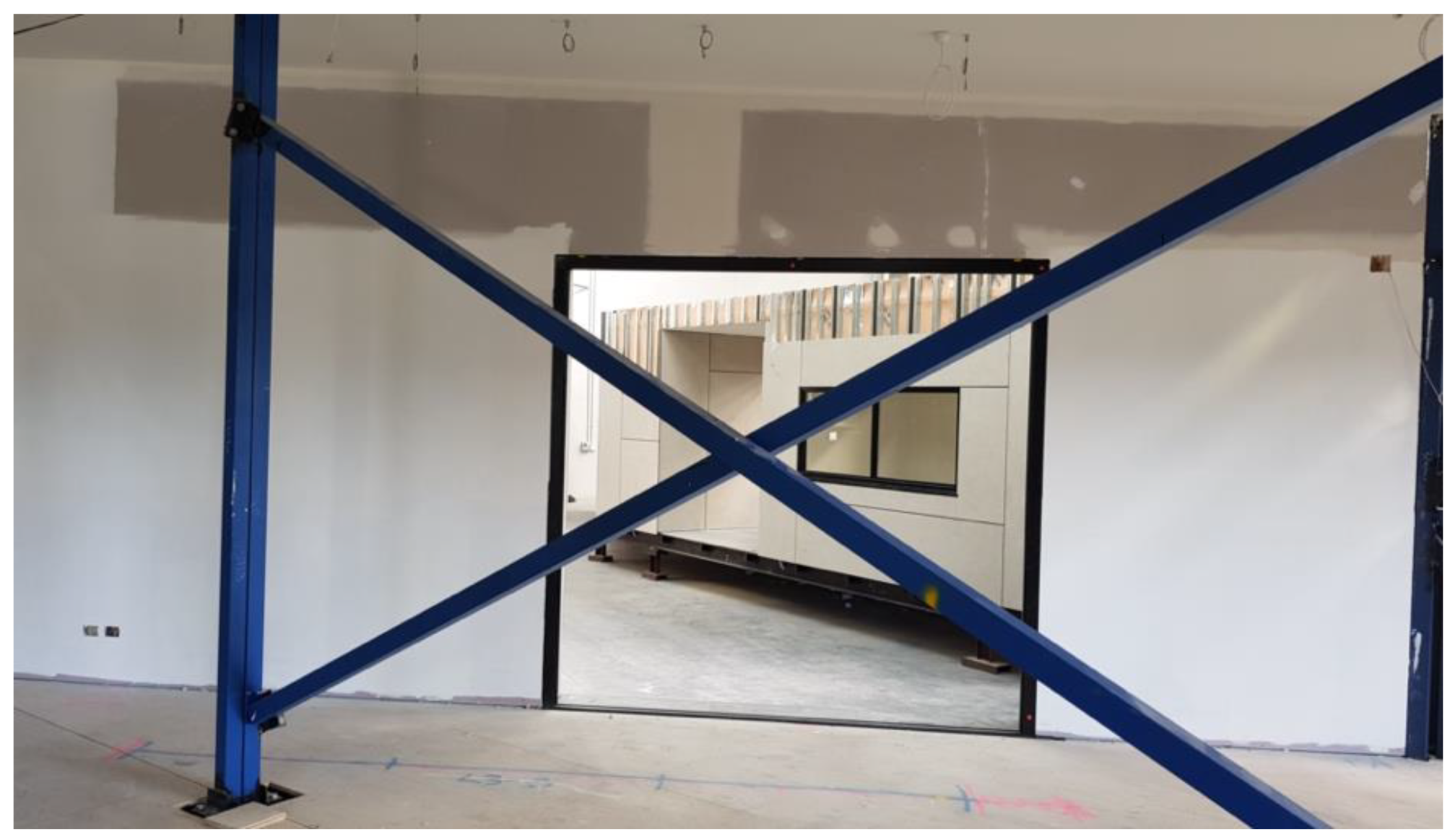
Temporary loads act on structures in any form of construction. In an in-situ construction, temporary loads are usually in the form of temporary live loads such as the weight of equipment, formwork and stored materials, in addition to the live load of construction workers. However, since on-site time is minimal in a prefab construction, temporary loads act on fully or partially finished modules or panels during their transport, lifting and handling. These loads that act on a structure during its transportation can be estimated according to the findings of some recent studies [25,26,27]. Although the stiffness of temporary bracing and the permanent structural frame should be checked against these loads, proper guidance on transportation-induced loading has not yet adequately appeared in the design standards of buildings. Much more groundwork in both research and practice needs to be carried out in achieving this. For the time being, it is prudent to overdesign the temporary bracings to encounter any unpredictable forces that the structure may undergo during all stages of its movement, since temporary bracings can be reused many times. As a result, as shown in Figure 4, temporary bracings and temporary columns are a common feature in modular construction at present.
3.2.2. Temporary Support Conditions
Similar to temporary loads, temporary support conditions also exist in any form of construction. In an in-situ construction, temporary support conditions can be commonly seen in situations such as a temporarily unbraced column or lift core that is usually cast ahead of the rest of the building. The transportation, lifting and handling stages and even the installation stage of a prefab construction would similarly impose temporary support conditions on a prefab structure.
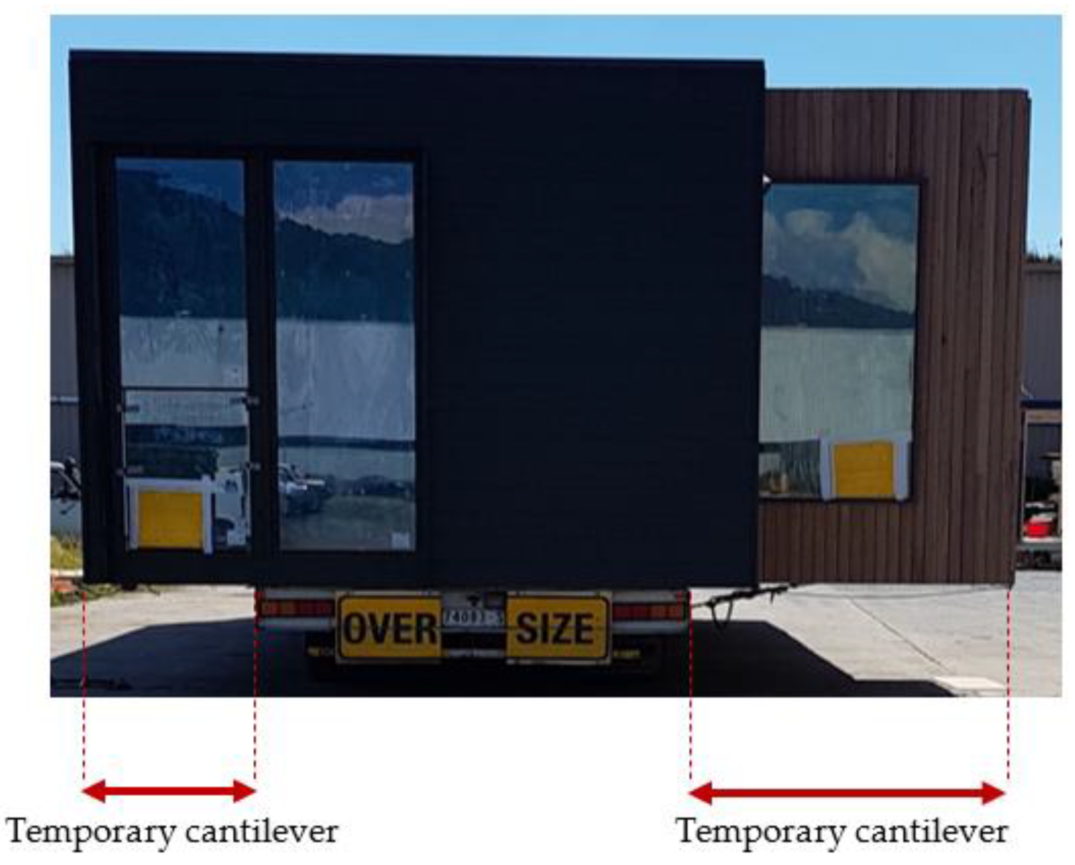
Figure 5 shows a situation where temporary cantilevers are imposed on a module while it is being transported due to its width being larger than the width of the truck bed. Such situations need to be foreseen by the structural engineer, especially since the details of the fleet of trucks accessible to the prefab builder can easily be known.
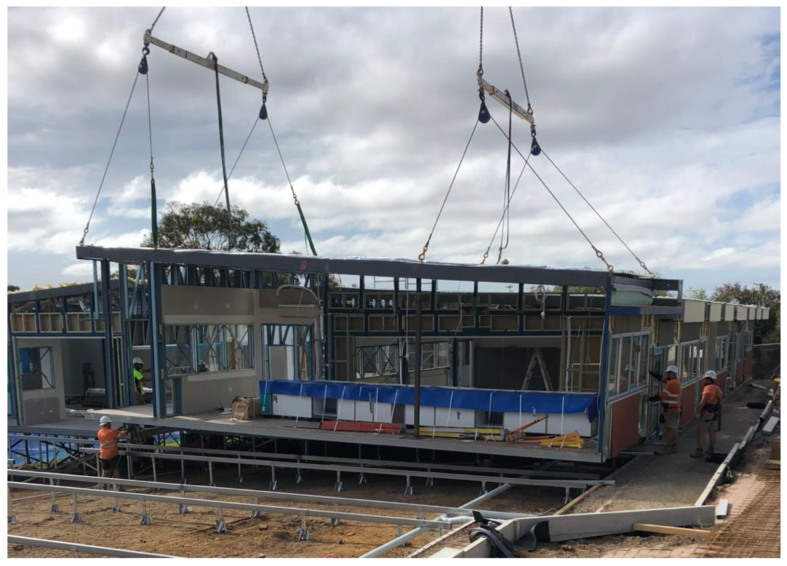
Similarly, the lifting and handling of prefab units impose temporary loads and support conditions on them. Top lifts and bottom lifts are the two main methods of lifting modular and panelised units. A top lift is commonly arranged with adjustable spreaders and chains that lift a unit from the top. These top lifts should ideally be carried out by connecting the lifting mechanism to structural columns which are adequately stiff to carry the tensile force applied on them when the full weight of the prefab unit acts upon them. Bottom lifts are carried out by connecting the lifting mechanism to the bottom of the module or panel, usually arranged with a single spreader beam on top.
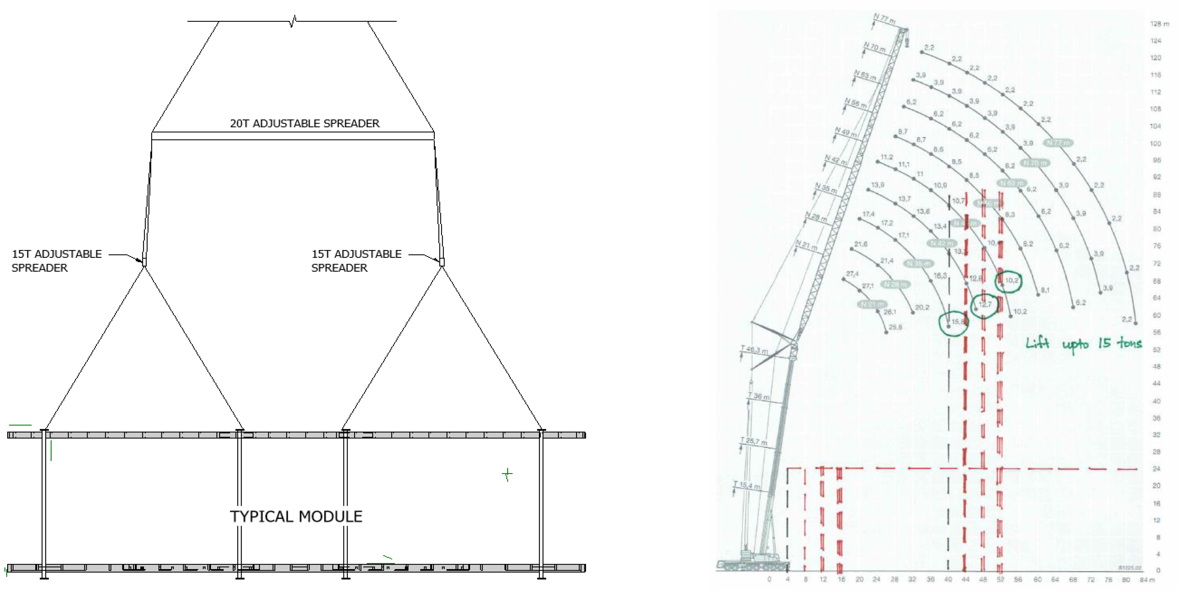
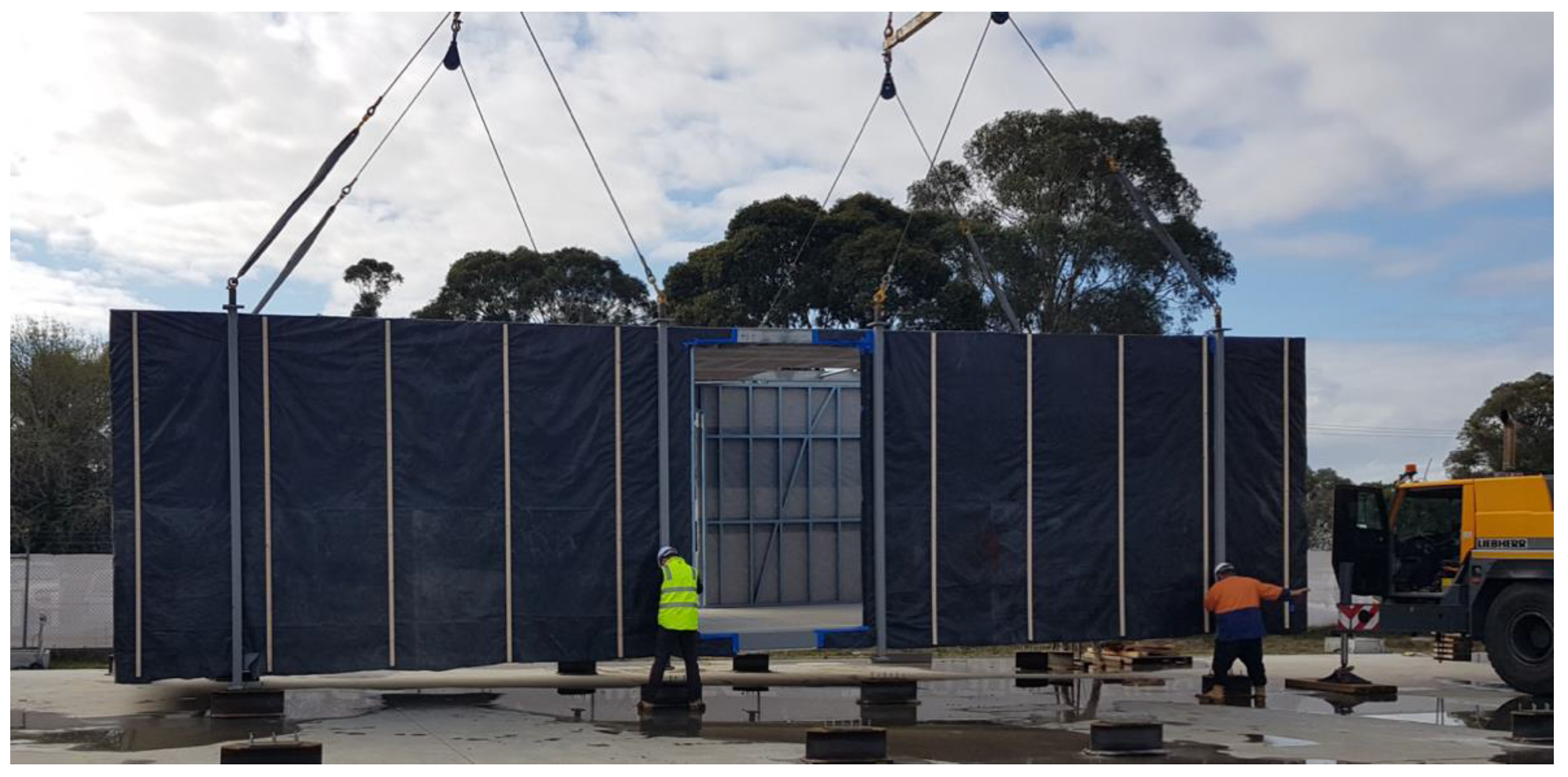
Unfortunately, certain unsafe practices are seen in lifting modules and panels, mainly due to the lack of adequate standards to provide guidance. Only precast concrete panels have well-established standards and guidelines, and these are not always directly applicable to modern modular or panellised units. Some contractors and even designers allow lifting points to be on roof beams or stub columns that are at times only temporarily welded to roof frames or floor frames. This is a practice that should be avoided, since temporarily welded elements are much less stiff than a full-length structural column, and can fail, especially at the welds, if one or two of the lifting chains are not in full tension. Such failures have occurred in practice, and they can be easily avoided by applying engineering common sense and proper preparation for the lift. The preparation should come from the structural design itself. The structural engineer must design and specify the complete lifting strategy and should not leave this to be a decision for the lifting contractor or the builder. Figure 6 shows an extract from a structural drawing that specifies the lifting strategy and how the lifting capacities are worked out using the capacities of the crane and the available lifting angles according to site conditions. Figure 7 shows an example of ‘good practice’ when it comes to lifting heavy modules from their full-length structural columns.
Lifting stability can be provided by designing for suitable lifting capacity from the mobile crane (or the tower crane). Most lifts end up being unstable and shaky due to the selection of cranes with capacities with an allowable lifting weight just above the actual weight of the prefab unit. It is observed in practice that a fairly stable lift can be achieved by selecting a mobile crane with a capacity that results in an allowable lifting weight which is around 2 to 3 times the actual weight of the prefab unit being lifted. The extra cost for hiring a larger capacity crane would be soon offset by achieving a faster installation due to having a more stable lift. It also helps, especially in lifting modules, if the structural design ensures an even weight distribution in the horizontal plane of the module (on floors and ceilings), so that the module can be lowered without being tilted to a side.
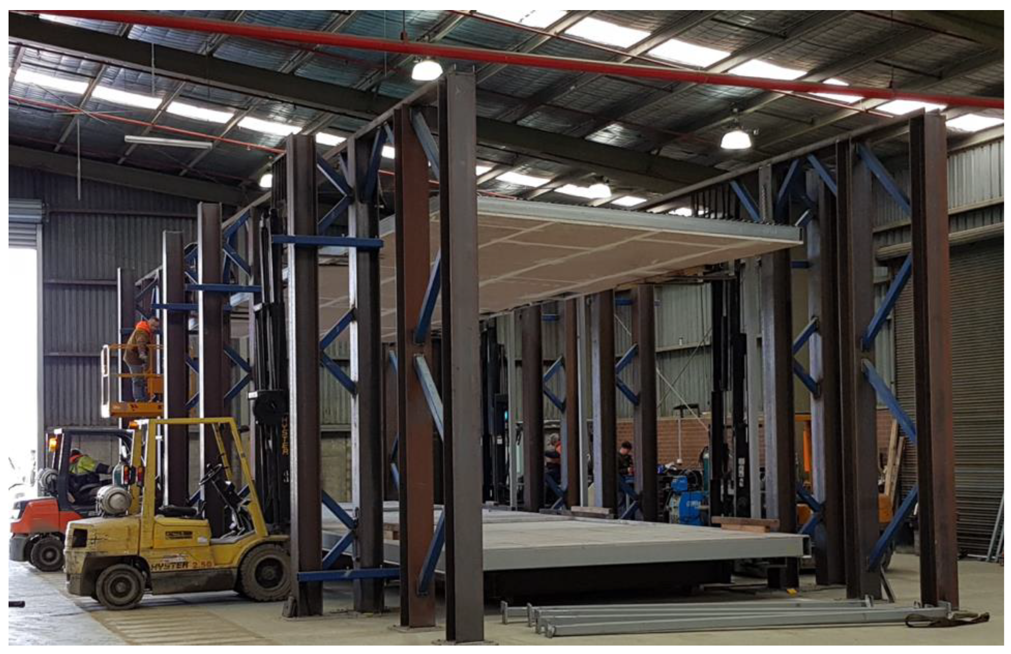
The handling of prefab units within the factory as well as onsite can impose loads and unforeseen support conditions. Depending on the capability of the prefab builder, various handling methods could be in place in an offsite manufacturing facility. Figure 8 shows a modular unit being handled with forklifts within a factory. Since manually operated forklifts cannot be fully synchronised, forces will be induced on the partially finished panels or modules when being handled in such a manner. More sophisticated facilities would at times have hydraulic mechanisms to handle prefab frames and they would have more damping to prevent any undue jerking forces being applied on the frames.
4. Strength Design for Ultimate Limit State
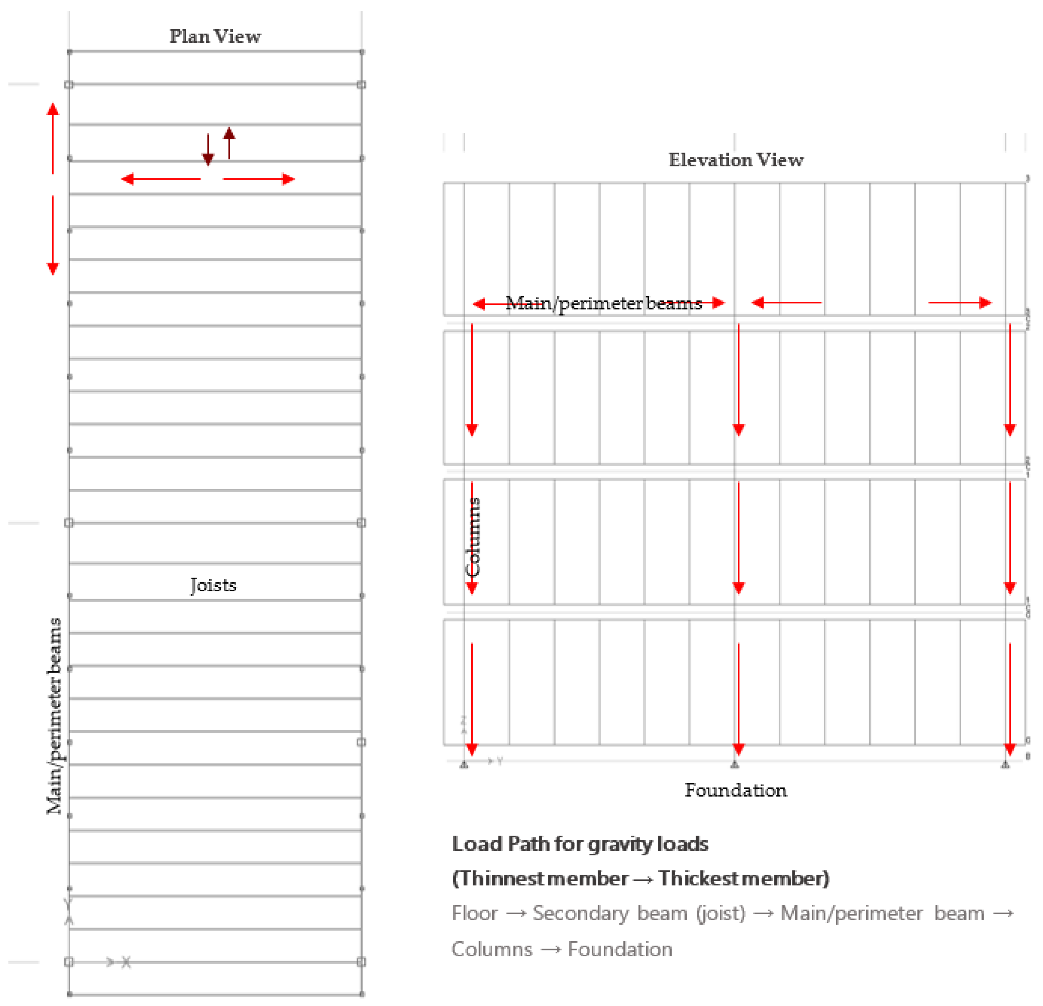
The strength design for ultimate limit state in a prefab structure would not be very different to that of an in situ built traditional structure. Eventually, the demand imposed by various combined vertical and lateral loads on each structural column, beam, floor system, ceiling frame, wall, roof member and connection are to be checked against their respective structural capacities (in bending, compression, tension, shear, torsion, etc.). To formulate the strength design of structural systems for prefab buildings, it is essential to understand the load paths taken by each type of load from their origin to their eventual transfer down to the foundation. Not understanding load paths adequately will lead to very inefficient structural designs in prefab buildings.
4.1. Gravity Loads (Vertical Loads)
In any structural form, gravity loads always take the path from the thinnest member (least stiff) to the thickest member (most stiff) in the direction of gravity. Gravity-load-resisting structural systems have developed over the years for traditional in-situ built structures, and very little needs to change for prefabricated structures, although some prefab designers seem to have over-complicated this. It is most advantageous for a structural system to be repeatable to allow for a more efficient offsite fabrication process following DfMA principles, as previously discussed. While there may be many architectural customisations, the structural system could still be designed to be repeatable (typification). The key to such a design is a minimalistic and efficient gravity load resisting structural system. This can then integrate into the larger superstructure with any additions such as building services, to form a wholistic structure (unification).
Due to the nature of many steel modular and flatpack building units, one-way spanning floor systems commonly provide the most cost-effective and structurally efficient floor designs. Their repeatability and simplicity in terms of the arrangement of structural members and lower number of welded or bolted joints results in a more efficient fabrication process compared to a two-way spanning floor frame. The same applies to ceiling or roof frames, resulting in a holistic and efficient DfMA design. Figure 9 shows the load paths in a typical module within a corner-supported modular structural system. Once the load paths are properly designed, each structural member can be checked for their structural capacities according to the relevant structural codes of practice (for example, AS 4100:2020 [24] for the design of steel members of structures in Australia).
4.2. Lateral Loads (Wind and Earthquake Loads)
Wind loads first need to be estimated according to the relevant loading standard (for example, AS 1170.2:2021 [19] for structures in Australia) and applied to a global structural analysis model to observe overall effects such as top deflection, inter-storey drifts and base moments. The design criteria of strength, stability and serviceability for prefabricated buildings against wind loads apply as follows:
- Stability—
- against overturning, uplift and/or sliding of the structure as a whole.
- Strength—
- capacity of the structural members in bending, shear, torsion, etc. are required to withstand without failure against wind loads applied under long return period winds (typically, 500- or 1000-year return period, decided according to the importance level and design life).
- Serviceability—
- where inter-storey and overall deflections are within acceptable limits. Wind accelerations also need to be checked for taller structures to ensure that the acceleration limits are within acceptable criteria for human perception of motion (typically, 25- or 50-year return period for deflections and 1- to 10-year return period for accelerations, decided according to the importance level and design life).
For a complex prefab structure, such as a tall building or a building that covers a large area, a load evaluation merely according to the loading standard may not be adequate. In such cases, a complete set of wind studies using a physical or virtual wind tunnel (using computational fluid dynamics) will be necessary to estimate the complete wind effects on the particular building [28,29]. The types of wind studies to consider are:
- 1
- Environmental wind studies—to study the wind effects on the surrounding environment caused by erecting a tall prefab building or a building with complex geometry (this study may also include a pedestrian wind comfort study for ground level and podium levels or terraces).
- 2
- Wind loads for the façade—to assess design wind pressures throughout the surface area of the building to design the cladding and façade system.
- 3
- Wind loads for the structure—to determine the design wind loads to design the lateral load-resisting structural system.
The earthquake performance of prefab buildings and their connections have been studied in detail in many recent studies [2,7,30,31]. As explained in these studies, the stiffness of the connections and how and where they connect to the main structural elements is critical in how they perform in transferring earthquake loads. Earthquake forces impact a building at its base, and propagates to higher levels as an inertial force according to the mass and stiffness of each level (or each module). The connections would transfer these loads in the form of shear forces to main structural elements. The connection to the foundation is also critical, since the mass of the building (dead load) acting on the columns would be the largest at ground level. As a result, the largest component of the earthquake shear would be felt at the ground level. The Australian standard AS1170.4:2007 [20] provides comprehensive guidance in estimating both static and dynamic earthquake forces for each type of structure.
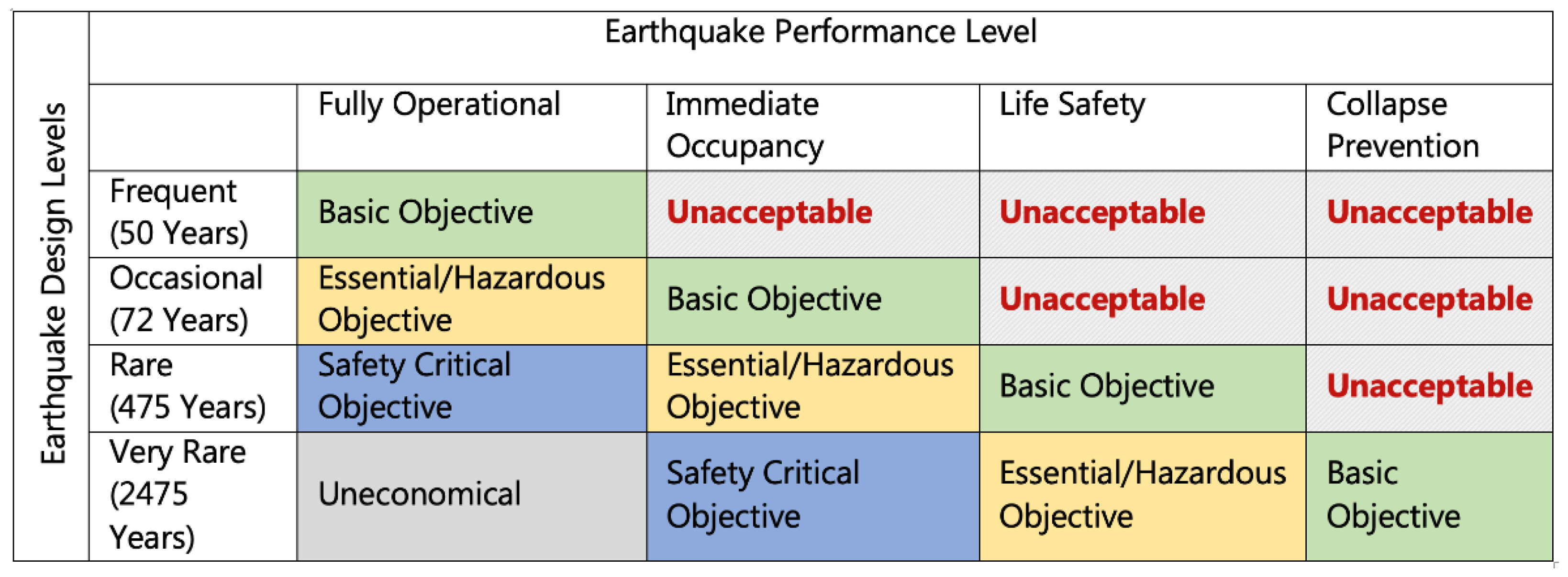
The code-based earthquake design is commonly known as a ‘force-based’ design approach. The force-based approach follows the commonly practiced limit state analysis principles, which are practiced through many design standards around the world. In addition, for the design of prefab buildings, a performance-based design approach may also be adopted. Performance-based design (also known as displacement-based design) focuses more on the performance aspects of the structure, such as its functionality and operability after an earthquake event, and is checked in relation to its target displacements or drifts under a given earthquake force. As one of the pioneering steps into performance-based seismic design (PBSD), the Structural Engineers Association of California (SEAOC) [32] proposed a framework (Figure 10) with target performance levels for the design and verification of new building constructions. Kappos and Panagopoulos [33] introduced more clarity into how PBSD could be employed through inelastic static and dynamic analyses, and check the design against the following target performance objectives:
- Two distinct performance objectives were ‘serviceability’ (damage limitation), which is typically associated with an earthquake probability of 50% in 50 years, and ‘life safety’, which is typically associated with an earthquake probability of 10% in 50 years, are explicitly considered. The basic strength level of the design of the structure does not relate to the ‘life safety’ criteria as in most existing codes, but to the serviceability criteria. A third performance objective in the form of ‘collapse prevention’, which is typically associated with an earthquake probability of 2% in 50 years is considered in the design against shear, and for the seismic detailing of elements.
- Inelasticity is also explicitly considered in the analysis, but is restricted only to those members that are considered as seismic energy dissipating zones (plastic hinge zones—see Figure 11) by the structural engineer. The well-established capacity design principles are followed in selecting these zones [34].
- The confinement detailing of critical structural members is also performance-based, i.e., it is determined according to the post-yield deformation requirements predicted from the inelastic analysis [35].
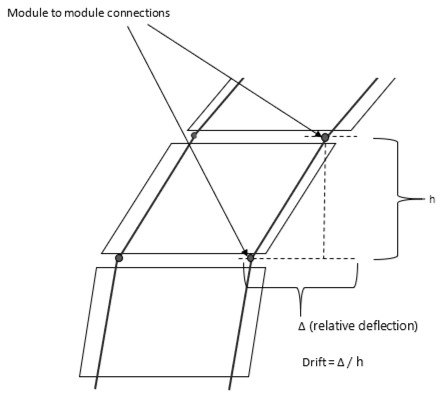
It is very important to check inter-storey drift against both wind and earthquake loads. Every modular floor in a corner-supported system has two different structural frames, as the roof or ceiling frame of the lower storey, and the floor frame of the upper storey. This makes the estimation of inter-storey drift uniquely different for corner-supported modular structural systems compared to any other structural form. For example, a traditional in situ building would have both these frames represented by a single slab or floor frame. Therefore, the inter-storey height can be defined as the height between two consecutive inter-modular connections, as shown in Figure 12, in estimating inter-storey drift.
5. Design of Connections (with a Worked Example)
Structural connections are the most uniquely different aspect of prefabricated structures compared to an in situ built structure. They are also the most critical structural component, which provides a prefabricated structure its buildability, speed of construction and overall effectiveness.
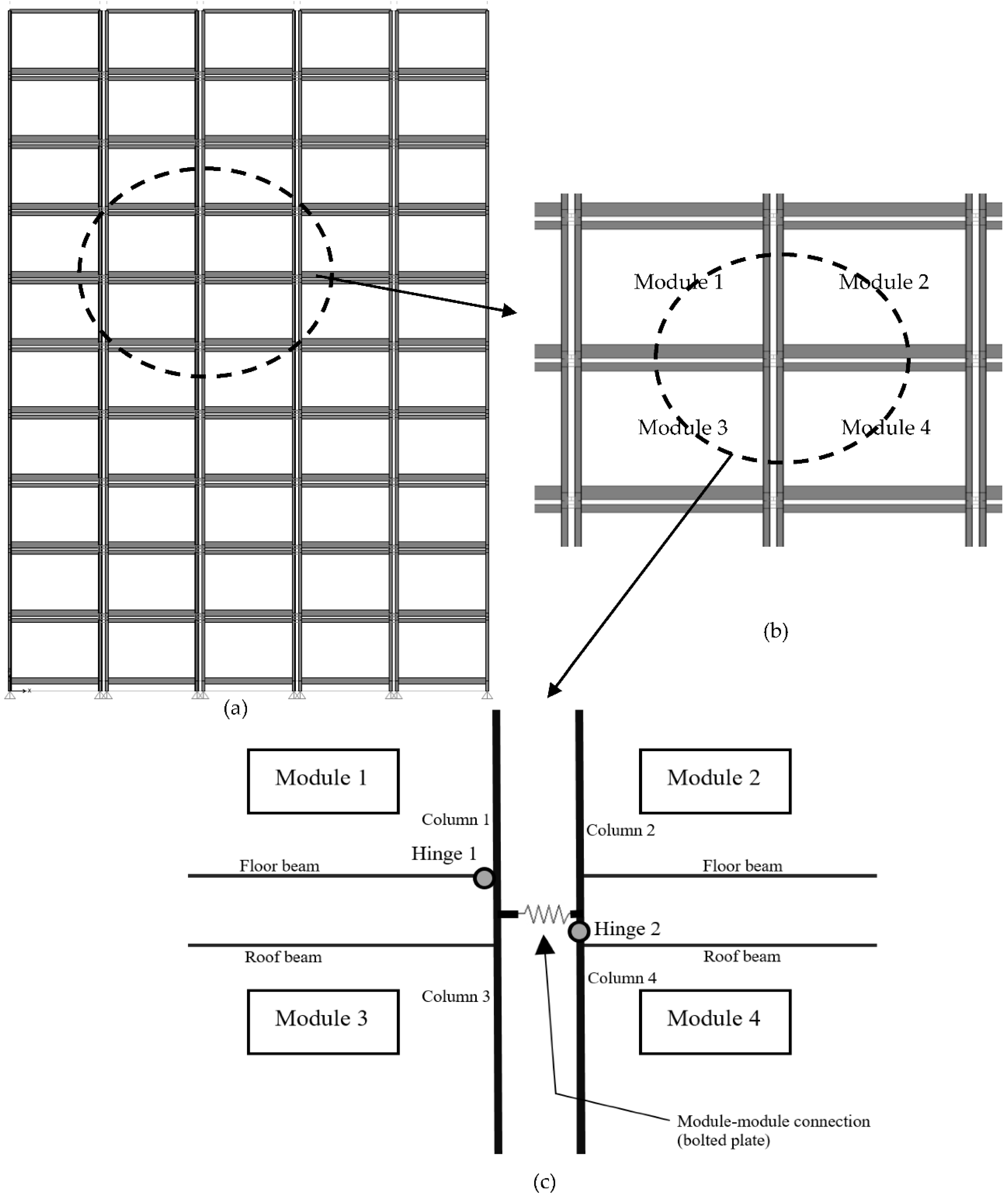
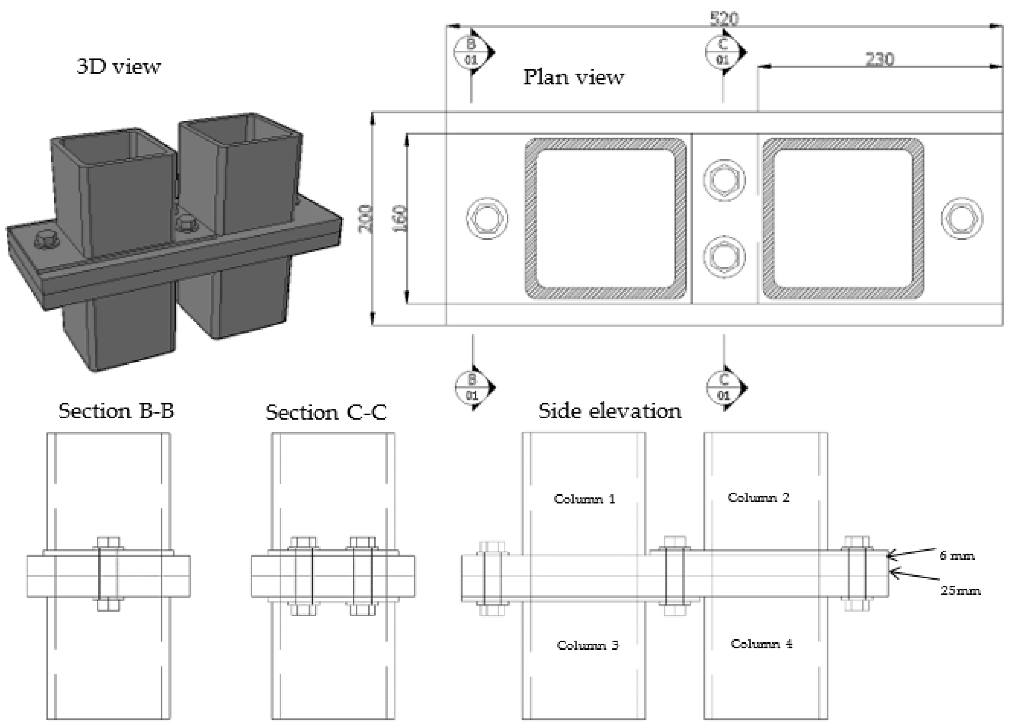
In the advanced corner-supported modular structural system introduced by Gunawardena et al. [7,8], the connections were designed in a way to connect neighbouring modules both laterally and vertically via the corner columns (Figure 12). The transfer of vertical and lateral loads is designed to occur via these bolted steel connections that connect two adjacent corner columns of two neighbouring modules. The details of this connection’s design are shown in Figure 13. The conceptual make-up of the connection was intended to be as generic as possible, so that any engineer is at liberty to follow the findings and recommendations of this study to create their own unique connection design.
The strength and serviceability limit states for the structural design of this connection were determined following the Australian steel design standard, AS4100:2020 [24]. The steps to its complete design calculation are shown in Section 5.1. The supporting guidelines provided by Gorenc et al. [36] were also followed in the design calculations in addition to the requirements of AS 4100:2020 [24]. It was assumed that the column sizes were all 150 mm × 150 mm × 9 mm SHS (square hollow section) members; and the material properties of the other components of this proposed connection design are listed in Table 2. Both gravity and lateral loads are transferred via this connection, thus it needs to resist the bearing and shear actions that are generated as a result. The lateral forces extracted from a global structural analysis can be used to estimate the design actions on such an inter-modular connection or a connection of a panelised structure.
5.1. Serviceability Limit State Design of the Connection
The design calculations for the serviceability limit state of the inter-modular connection shown in Figure 13 are explained in this section. This connection needs to be treated as a ‘slip critical’ connection due its geometric position and orientation in the overall structure and the type of actions that it would undergo during an earthquake. The Australian standard AS 4100:2020 [24] addresses slip failure as a serviceability limit sate criterion and the slip resistance (Vsf) is calculated as follows:
where,
- = Coefficient of friction between plies
- = Number of shear planes
- = Minimum pretension imparted on the bolts during installation
- = Factor for hole type (1.0 for standard holes, 0.85 for oversized holes and short slotted holes, and 0.70 for long slotted holes)
Following the AJAX Fastener Handbook [37], a value of 31.8 kN is considered for Nti and the calculation for slip resistance is as follows:
Therefore, the slip would occur at a load of 6.36 kN for one bolt in the given connection. The total slip resistance of the entire inter-modular connection is 25.44 kN (6.36 × 4).
To be prudent, a low coefficient of friction (), such as 0.2 or 0.15, can be considered to anticipate the worst-case slip scenario. In reality, the connection would have protective coatings for durability and fire resistance applied on its components. Such coatings or paints could also result in low coefficients of friction in all relevant slip planes. As a conservative yet practical solution, a larger bolt size can be used to achieve a higher slip resistance, since it would require a higher bolt pre-tension.
5.2. Strength Limit State Design of the Connection
The design calculations for the strength (ultimate) limit state of the inter-modular connection shown in Figure 13 are explained in this section. As per AS4100:2020 [24], the strength limit state design of a bolted steel plate would need to be checked for its shear capacity, bearing capacity and tear-out failure capacity.
Considering no shear planes in the threaded region, the shear capacity (Vf) is calculated as follows:
where,
- = Reduction factor for length of bolt line (bears a value of 1.0 for connections other than lap connections)
- = Minimum tensile strength of the bolt
- = Number of shear planes in the unthreaded region
- = Bolt shank area
The calculation for one bolt is as follows:
Therefore, the shear capacity of all four bolts would be 224.4 kN (56.1 kN × 4). A further capacity reduction factor of 0.8 applies over this value for the design shear capacity of the connection as per AS 4100:2020 [24] resulting in a design shear capacity of 179.5 kN.
Check for bearing (Vb) is as follows:
where,
- = Thickness of the ply
- = Minimum tensile strength of the ply
- = Bolt diameter
The calculation for one of the 6 mm plies for crushing under the pre-tension of one of the bolts is as follows:
Therefore, all bolt pre-tensions applied need to be less than 103.7 kN each.
Check for tear-out failure (Vp) is as follows:
where,
- = Minimum distance from the ply edge to the centre of the hole in the direction of the bearing load
The calculation for one of the 6 mm plies for tear-out near one of the bolts is as follows:
Therefore, the tear-out capacity of the entire inter-modular connection would be 378 kN (94.5 kN × 4). This value is higher than the shear capacity of the connection. Therefore, it can be deduced here that checking for shear capacity would satisfy the other two failure criteria as well.
Following an experimental investigation on this inter-modular connection, Gunawardena [7] observed that subsequent to slip failure, the bolts transfer into a stage where they resist a combined shear and bearing action. Therefore, the critical design criterion is the check for combined shear and tension.
The combined capacity for shear and tensile bearing can be checked for the design values as follows:
where,
- = nominal tension capacity of a bolt
- = design tensile force on a bolt
- = 0.8 for combined actions
Once the capacities of the connection design are calculated as above, they can be compared with the forces obtained from a global structural analysis. With a consideration on maintaining the slip resistance, it would be prudent to increase bolt size prior to increasing the number of bolts where the design capacities are not adequate.
6. Importance of Structural Detailing
Clear and precise structural detailing is essential in effectively communicating a structural design to the builder and other operators of a construction. This requirement is even more critical in prefab construction, as the onsite tolerances are quite small in high-precision assembly of prefabricated panelised and modular units. In a DfMA setup, precise detailing contributes significantly to ensuring the smooth-functioning of the manufacturing and assembly line of prefab units. Due to the high demand for producing prefab units in a short period of time, there is no time go back and forth with traditional RFIs (requests for information) within a prefab facility. Therefore, clear and precise detailing is key to an efficient and error-free prefab production line.
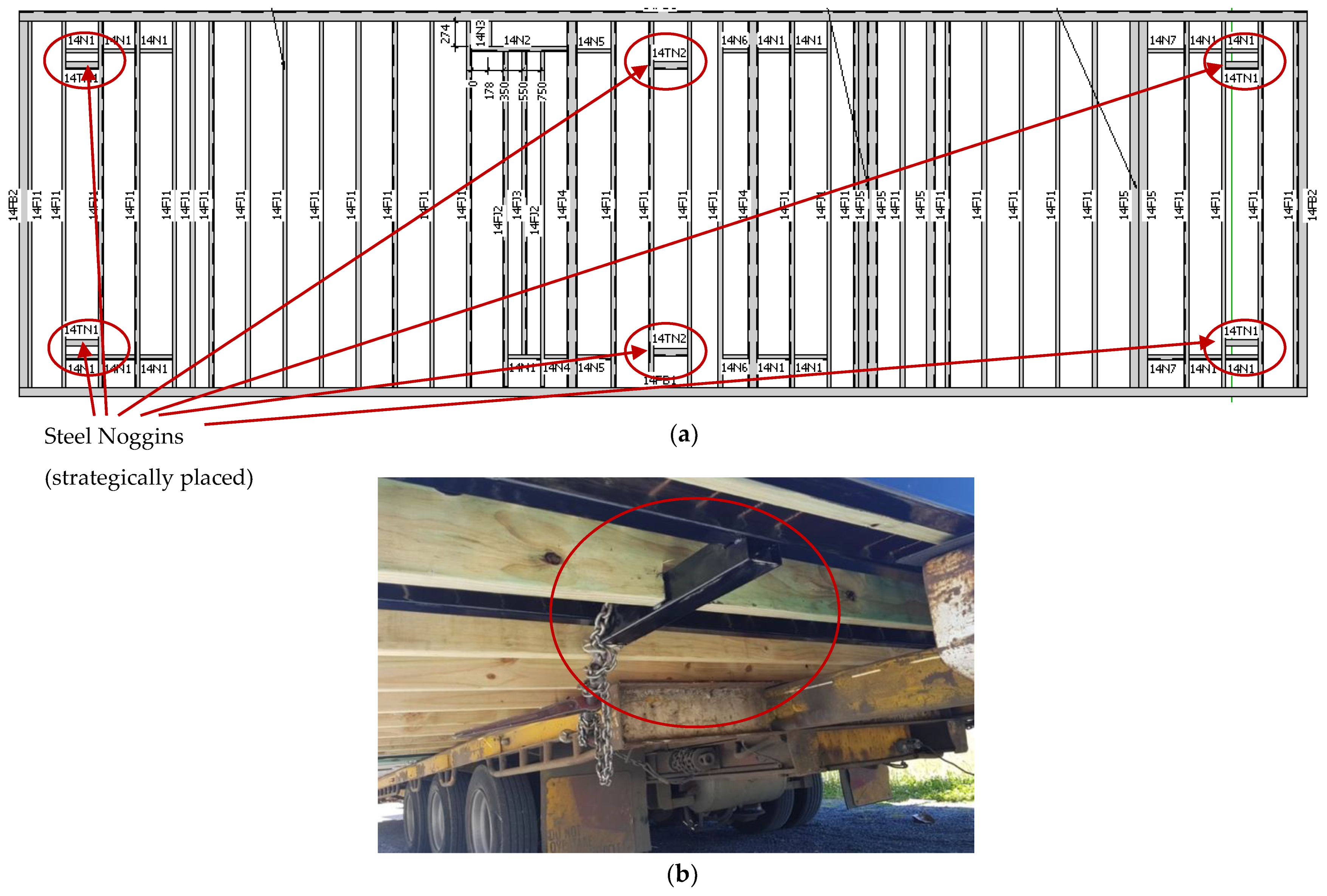
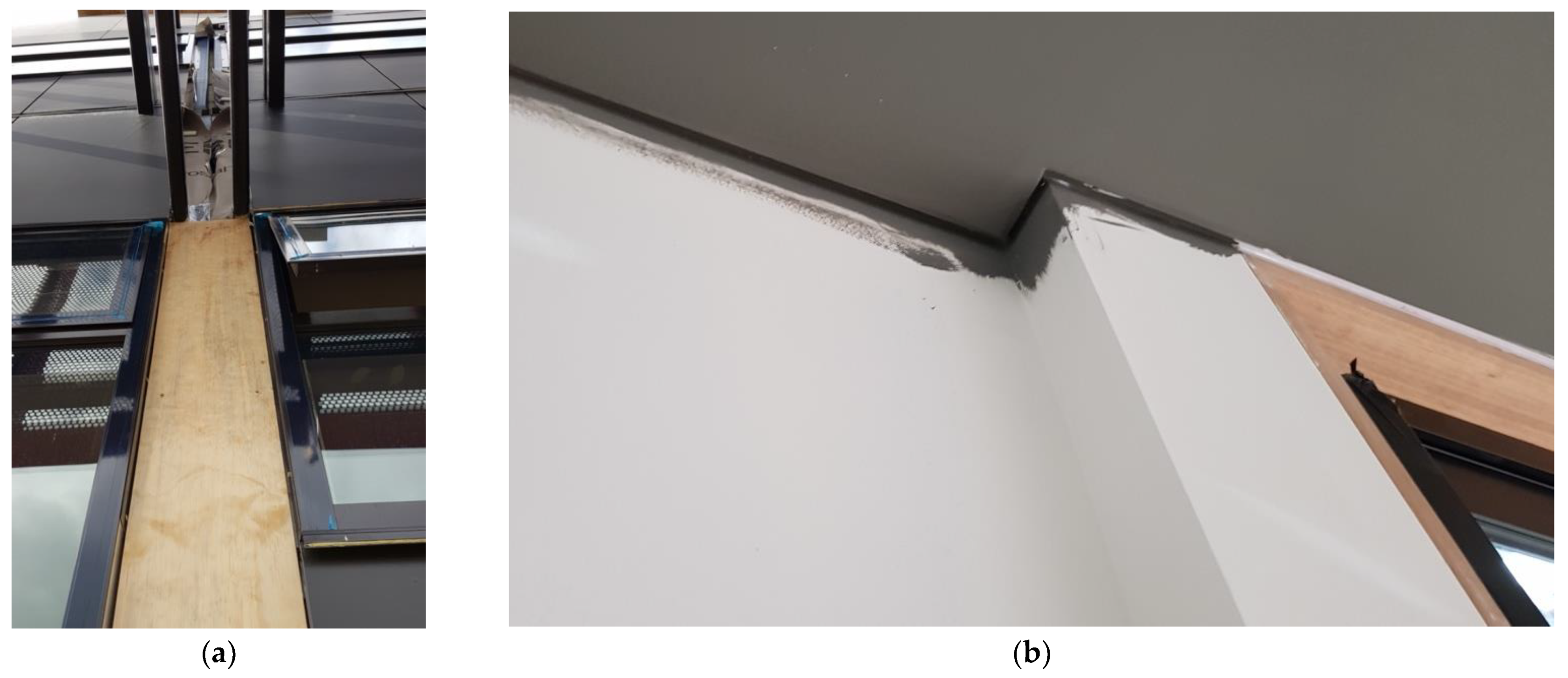
In addition to the abovementioned requirement of providing precision and adequate detail for the manufacturing stage, structural detailing becomes quite necessary for other stages of a prefab construction as well. Figure 14 shows how a structural floor design of a modular unit is detailed with strategically placed steel noggins to enable the tying down of the module to the trailer bed of the particular transport vehicle. This in turn implies the necessity to know the fleet of trucks at the builder’s disposal during the design stage, as discussed previously. Figure 15a shows how the structural detailing allows for the easy installation of structural modules (this method is also applicable for panels) by leaving a post-installation strip in the façade or cladding. The external skin of a building needs to be watertight and connect seamlessly at all joints. Unless a special gasket connection is designed, for the façade joint, a watertight connection would result in a very time-consuming installation process. Therefore, to allow for a fast installation, most builders leave a post-installation strip for the façade or external cladding which could be installed after all the modules are fully installed. This detail needs to be provided in the design. Figure 15b shows how structural detailing needs to be provided for internal finishes such as plasterboard joints. It is prudent to leave a movement gap between brittle plasterboards at ceiling to wall and floor to wall joints, since they may produce cracks during transportation, lifting and handling if joined rigidly. A good practice solution to this would be to leave a gap at these joints to behave as a movement joint and cover them up with cornices (at ceilings) and skirtings (at floorings) afterwards.
7. Construction Technology
7.1. Factory-Based Fabrication (Offsite Manufacturing)
Offsite manufacturing transforms many of the more site-intensive construction activities of traditional construction to in-house activities within a prefab manufacturing facility. This not only ensures a greater overall quality of the product, since it is under more organised supervision and monitoring, but also significantly improves the occupational health and safety of construction workers.
A great degree of automation is commonly seen in the manufacturing of panelised units, with automated assembly lines including a fair amount of robotics. However, such a level of automation is seldom seen in the manufacturing of modular units in most parts of the world. Regardless of the level of automation, the level of accuracy must be maintained at very high levels at all times to make sure that on-site installation can proceed without unnecessary delays due to manufacturing defects. Due to this reason, manufacturing tolerances must ideally be kept lower than the traditionally allowed construction tolerances. Design and practice standards and guidelines will need to change to take this into consideration.
In ensuring manufacturing accuracy, the movement within the assembly line or each stage of manufacturing needs to be planned carefully. Especially for modular units, it must be noted that a module needs to achieve its full rigidity before moving from its structural framing stage to a different stage. If a module is not rigid enough before being moved, the handling itself could alter its geometry and location of connections and cause issues during installation if the error goes undetected, and worse if the error accumulates.
7.2. Importance of Prototyping
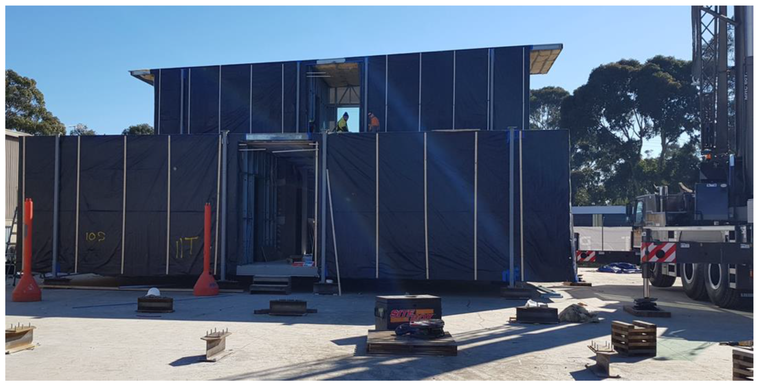
Since there is no room for error once the prefab units reach the construction site, all measures must be taken to ensure accuracy while the units are still within the builder’s manufacturing facility. Prototyping is an essential activity that provides an opportunity to a builder to inspect the installation process beforehand. All aspects related to buildability, such as access to connections, safety of installers, accuracy of installing sequence and adequacy of tolerances can all be checked during a well-organised prototyping activity. Figure 16 shows a full-scale prototyping of a double-storey modular building carried out at an offsite manufacturing facility. While this activity would point out all practical issues as previously explained, it also stands as a testament to the full reusability and relocatability of such prefab modules, since the modules would need be fully disassembled from their inter-modular connections before being transported to site to be assembled again.
While most builders would prefer a full-scale prototyping of the real structure, the continuous increase in the demand for prefabricated buildings may not warrant this in the future. Rapid prototyping methods such as 3D printing provide the solution to carry out accurate, small-scale and quick prototype checks. Figure 17 shows a small-scale 3D printed rapid prototype of a façade extrusion against a full-scale prototype of an inter-modular connection. Both were prepared for similar reasons and provided similar inputs to the builder. However, the latter used less labour, time and cost in preparation. This highlights the advantage of using rapid prototyping methods for the naturally fast-paced prefab industry.
7.3. Prefab Foundations
Most multi-storey modular and panelised structures are still largely built on top of in-situ built foundations and basements. Prefabrication is yet to develop to a level where underground structures, such as carparks, with retaining walls and proper waterproofing can be constructed with fully prefab units. However, there are prefab foundation methods that have been successfully used in low-rise prefab buildings, as shown in Figure 18, and some initial research work has been carried out on their performance [38]. These foundations are usually built with driven piles where the prefab structure transfers its weight to the piles via steel bearers (ground beams) and base plates.
The technology for prefabricated foundations, especially with regard to deep foundations with basements for high-rise structures, stands out as one of the critical areas for future improvement demanding a considerable amount of research. This may need to be looked into together with prefabricating structural cores, since together, these activities form the backbone of the critical path in a typical high-rise construction. The ‘advanced corner supported prefab structural system’ proposed by Gunawardena et al. [7,8] could prove to be an initial step for such concepts.
7.4. Modular Building Services (MEP)
Similar to prefab foundations, technologies for prefabricating mechanical, electrical and plumbing (MEP) works, commonly known as building services, is also a less-explored area in prefab construction. Only a handful of recent research work has captured the need for modular MEP systems and introduced concepts to practically implement them [39,40,41]. However, the industry uptake of these concepts seems to be slow. There is a critical need to modularise MEP systems in prefab buildings, since the installation of building services currently takes up a considerable amount of time and remains a bottleneck in most prefab design and construction schedules. Modular MEP systems need to be adopted more frequently for them to be recognised and regulated by design standards and for them to develop further to fill a critical gap in the prefab industry. Design for building acoustics and thermal and fire performance could also be included in this category, and similar need for more detailed research as well as industry uptake exists in making these systems integrated more efficiently into the modular or prefab setup [42,43,44].
8. Conclusions and Prospects
Prefab technology has initiated a remarkable transformation in modern construction by reducing the amount of on-site activities and the time spent, with the help of efficient offsite manufacturing. The inclusion of Design for Manufacturing and Assembly (DfMA) is enabling a rapid evolution in the construction industry and design practice by creating better-performing prefab systems that reduce factory overheads and enable more automation. A combination of these technologies will realise projects even faster and generate better profit margins for investors. In addition to fast constructions, offsite manufacturing will also create a more quality-oriented practice and a safer working environment for upskilled building technicians.
The structural design of prefab systems and their connections still need to follow the basic principles of structural design and satisfy strength, serviceability and stability criteria. In a fundamental sense, prefab structural systems should not differ by any means from traditional structural systems in achieving the required performance. Designers need to provide the capability of easy installation on site, and easy accessibility to connections even after installation. The overall geometry, rigidity and weight of modules would need to satisfy lifting, transportability and assembly criteria to make any prefabricated system viable.
Where skilled labour is diminishing as a resource globally, it would be prudent to invest more in prefabrication technologies, supported by more detailed research. Further, prefab builders would also benefit from various economies of scale by having a factory-oriented process with minimum on-site costs. The disassembly and reusability aspects add another dimension into the value, by improving the sustainability and reducing the overall carbon footprint of a construction. Automation in manufacturing, with the use of robotics, and enhanced productivity, with the use of artificial intelligence, can further enhance the future value of offsite manufacturing.
Author Contributions
Conceptualisation, T.G. and P.M., methodology, T.G., formal analysis, T.G., investigation, T.G., resources, T.G. and P.M., writing—original draft preparation, T.G, writing-review and editing, T.G. and P.M. All authors have read and agreed to the published version of the manuscript.
Funding
This research was funded by the Australian Research Council Industrial Transformation Research Programme, IC150100023: ARC Training Centre for Advanced Manufacturing of Prefabricated Housing.
Acknowledgments
The authors acknowledge with gratitude the support given by industry partner Prebuilt Pty Ltd., Australia by providing access to their manufacturing facility and projects to which the authors have contributed.
Conflicts of Interest
The authors declare no conflict of interest.
Entry Link on the Encyclopedia Platform
References
- Gunawardena, T.; Ngo, T.; Mendis, P.; Aye, L.; Crawford, R. Time-Efficient Post-Disaster Housing Reconstruction with Prefabricated Modular Structures. Open House Int. 2014, 39, 59–69. Available online: https://0-www-scopus-com.brum.beds.ac.uk/inward/record.uri?eid=2-s2.0-84929162675&partnerID=40&md5=b34c27beef2b3323975d693c4aa48046 (accessed on 17 December 2021). [CrossRef]
- Gunawardena, T.; Ngo, T.; Mendis, P.; Kumar, S. Performance of multi-storey prefabricated modular buildings with infill concrete walls subjected to earthquake loads. Concr. Aust. 2017, 43, 51–58. [Google Scholar]
- Navaratnam, S.; Ngo, T.; Gunawardena, T.; Henderson, D. Performance Review of Prefabricated Building Systems and Future Research in Australia. Buildings 2019, 9, 38. [Google Scholar] [CrossRef]
- Gunawardena, T.; Mendis, P.; Ngo, T.; Rismanchi, B.; Aye, L. Effective Use of Offsite Manufacturing for Public Infrastructure Projects in Australia. Presented at the International Conference on Smart Infrastructure and Construction 2019 (ICSIC), Cambridge, UK, 8–10 July 2019; Available online: https://0-www-icevirtuallibrary-com.brum.beds.ac.uk/doi/abs/10.1680/icsic.64669.267 (accessed on 17 December 2021).
- Aye, L.; Ngo, T.; Crawford, R.H.; Gammampila, R.; Mendis, P. Life cycle greenhouse gas emissions and energy analysis of prefabricated reusable building modules. Energy Build. 2012, 47, 159–168. [Google Scholar] [CrossRef]
- Lawson, R.M.; Ogden, R.G.; Bergin, R. Application of Modular Construction in High-Rise Buildings. J. Arch. Eng. 2012, 18, 148–154. [Google Scholar] [CrossRef]
- Gunawardena, T. Behaviour of Prefabricated Modular Buildings Subjected to Lateral Loads. 2016. Available online: http://hdl.handle.net/11343/123961 (accessed on 17 December 2021).
- Gunawardena, T.; Ngo, T.; Mendis, P.; Alfano, J. Innovative Flexible Structural System Using Prefabricated Modules. J. Arch. Eng. 2016, 22, 05016003. [Google Scholar] [CrossRef]
- Peiris, P.A.N.; Hui, F.K.P.; Ngo, T.; Duffield, C.; Garcia, M.G. A Case Study on Early Stage Adoption of Lean Practices in Prefabricated Construction Industry. In ICSECM 2019; Dissanayake, R., Mendis, P., Weerasekera, K., De Silva, S., Fernando, S., Eds.; Springer: Singapore, 2021; pp. 589–600. [Google Scholar]
- Sepasgozar, S.; Hui, F.; Shirowzhan, S.; Foroozanfar, M.; Yang, L.; Aye, L. Lean Practices Using Building Information Modeling (BIM) and Digital Twinning for Sustainable Construction. Sustainability 2020, 13, 161. [Google Scholar] [CrossRef]
- Hijazi, A.A.; Perera, S.; Calheiros, R.N.; Alashwal, A. Rationale for the Integration of BIM and Blockchain for the Construction Supply Chain Data Delivery: A Systematic Literature Review and Validation through Focus Group. J. Constr. Eng. Manag. 2021, 147, 03121005. [Google Scholar] [CrossRef]
- Nanayakkara, S.; Perera, S.; Senaratne, S.; Weerasuriya, G.T.; Bandara, H.M.N.D. Blockchain and Smart Contracts: A Solution for Payment Issues in Construction Supply Chains. Informatics 2021, 8, 36. Available online: https://0-www-mdpi-com.brum.beds.ac.uk/2227-9709/8/2/36 (accessed on 17 December 2021). [CrossRef]
- Rodrigo, M.N.N.; Perera, S.; Senaratne, S.; Jin, X. Potential Application of Blockchain Technology for Embodied Carbon Estimating in Construction Supply Chains. Buildings 2020, 10, 140. Available online: https://0-www-mdpi-com.brum.beds.ac.uk/2075-5309/10/8/140 (accessed on 17 December 2021). [CrossRef]
- Transporting Houses and Prefabricated Buildings. 2018. Available online: https://www.vicroads.vic.gov.au/business-and-industry/heavy-vehicle-industry/heavy-vehicle-road-safety/transporting-houses-and-prefabricated-buildings (accessed on 17 December 2021).
- Standards Australia. AS 3600:2018 Concrete Structures; Standards Australia: Sydney, NSW, Australia, 2018. [Google Scholar]
- Jayasinghe, T.; Gunawardena, T.; Mendis, P. Advancements in Concrete Technology for Offsite Manufactured Buildings and Infrastructure Systems. In Proceedings of the CONCRETE 2021, Concrete Institute of Australia’s Biennial National Conference, Perth, WA, Australia, 5–8 September 2021. [Google Scholar]
- Standards Australia. AS 1170.0:2002 Structural Design Actions General Principles; Standards Australia: Sydney, NSW, Australia, 2002. [Google Scholar]
- Standards Australia. AS 1170.1:2002 Structural Design Actions Permanent, Imposed and Other Actions; Standards Australia: Sydney, NSW, Australia, 2002. [Google Scholar]
- Standards Australia. AS 1170.2:2021 Structural Design Actions Wind Actions; Standards Australia: Sydney, NSW, Australia, 2021. [Google Scholar]
- Standards Australia. AS 1170.4:2007 Structural Design Actions, Part 4: Earthquake Actions in Australia; Standards Australia: Sydney, NSW, Australia, 2007. [Google Scholar]
- Annamalai, K.; Naiju, C.; Karthik, S.; Prashanth, M.M. Early Cost Estimate of Product during Design Stage Using Design for Manufacturing and Assembly (DFMA) Principles. Adv. Mater. Res. 2012, 622–623, 540–544. Available online: https://0-search-ebscohost-com.brum.beds.ac.uk/login.aspx?direct=true&AuthType=sso&db=edo&AN=ejs29232997&site=eds-live&scope=site&custid=s2775460 (accessed on 17 December 2021). [CrossRef]
- Jovicic, G.; Lukic, D.; Todic, V.; Milosevic, M.; Vukman, J. Design for manufacturing and assembly within design for excellence: Approaches, methods and methodologies. Tehnika 2014, 69, 233–242. [Google Scholar] [CrossRef]
- Leaney, P.; Wittenberg, G. Design for Assembling. Assem. Autom. 1992, 12, 8–17. [Google Scholar] [CrossRef]
- Standards Australia. AS 4100:2020 Steel Structures; Standards Australia: Sydney, NSW, Australia, 2020. [Google Scholar]
- Godbole, S.; Lam, N.; Mafas, M.; Fernando, S.; Gad, E.; Hashemi, J. Dynamic loading on a prefabricated modular unit of a building during road transportation. J. Build. Eng. 2018, 18, 260–269. [Google Scholar] [CrossRef]
- Godbole, S.; Lam, N.; Mafas, M.; Gad, E. Pounding of a modular building unit during road transportation. J. Build. Eng. 2020, 36, 102120. [Google Scholar] [CrossRef]
- Godbole, S.; Lam, N.; Muhinadeen, M.M.M. Vehicle–road interaction analysis for pounding between cargo and trailer-bed. Veh. Syst. Dyn. 2019, 59, 547–567. [Google Scholar] [CrossRef]
- Abu-Zidan, Y.; Mendis, P.; Gunawardena, T. Optimising the computational domain size in CFD simulations of tall buildings. Heliyon 2021, 7, e06723. [Google Scholar] [CrossRef] [PubMed]
- Abu-Zidan, Y.; Mendis, P.; Gunawardena, T. Impact of atmospheric boundary layer inhomogeneity in CFD simulations of tall buildings. Heliyon 2020, 6, e04274. [Google Scholar] [CrossRef]
- Gunawardena, T.; Ngo, T.; Mendis, P. Behaviour of Multi-Storey Prefabricated Modular Buildings under seismic loads. Earthq. Struct. 2016, 11, 1061–1076. [Google Scholar] [CrossRef]
- Gunawardena, T.; Ngo, T.; Mendis, P.; Aye, L.; Alfano, J. Structural performance under lateral loads of innovative prefabricated modular structures. In From Materials to Structures: Advancement through Innovation. In Proceedings of the 22nd Australasian Conference on the Mechanics of Structures and Materials, ACMSM 2012, Sydney, NSW, Australia, 11–14 December 2012; Taylor and Francis: London, UK, 2013; pp. 717–722. Available online: http://0-www-scopus-com.brum.beds.ac.uk/inward/record.url?eid=2-s2.0-84881164688&partnerID=MN8TOARS (accessed on 17 December 2021).
- Structural Engineers Association of California. Recommended Lateral Force Requirements and Commentary, 7th ed.; Structural Engineers Association of California: Sacramento, CA, USA, 1999. [Google Scholar]
- Kappos, A.; Panagopoulos, G. Performance-Based Seismic Design of 3D R/C Buildings Using Inelastic Static and Dynamic Analysis Procedures. ISET J. Earthq. Technol. 2004, 41, 141–158. [Google Scholar]
- Paulay, T.; Priestly, M.J.N. Seismic Design of Reinforced Concrete and Masonry Buildings; Wiley: New York, NY, USA, 1992. [Google Scholar]
- Menegon, S.J.; Wilson, J.L.; Lam, N.T.K.; McBean, P. RC walls in Australia: Seismic design and detailing to AS 1170.4 and AS 3600. Aust. J. Struct. Eng. 2018, 19, 67–84. [Google Scholar] [CrossRef]
- Gorenc, B.; Tinyou, R.; Syam, A. Steel Designers’ Handbook, 8th ed.; USNW Press: Kensington, NSW, Australia, 2012. [Google Scholar]
- AJAX. Fastener Handbook: Bolt Products; AJAX Fasteners: Braeside, VIC, Australia, 1999. [Google Scholar]
- Teodosio, B.; Baduge, K.S.K.; Mendis, P.; Heath, D.J. Prefabrication of substructures for single-detached dwellings on reactive soils: A review of existing systems and design challenges. Aust. J. Civ. Eng. 2019, 17, 120–133. [Google Scholar] [CrossRef]
- Samarasinghe, T.; Gunawardena, T.; Mendis, P.; Sofi, M.; Aye, L. Dependency Structure Matrix and Hierarchical Clustering based algorithm for optimum module identification in MEP systems. Autom. Constr. 2019, 104, 153–178. [Google Scholar] [CrossRef]
- Samarasinghe, T.; Mendis, P.; Aye, L.; Gunawardena, D.; Karunaratne, R. BIM and Modular MEP Systems for Super-Tall and Mega-Tall Buildings. 2017. Available online: http://hdl.handle.net/11343/197525 (accessed on 17 December 2021).
- Samarasinghe, T.; Mendis, P.; Aye, L.; Vassos, T. Applications of Design for Excellence in Prefabricated Building Services Systems. In Proceedings of the 7th International Conference on Sustainable Built Environment (ICSBE), Kandy, Sri Lanka, 16–18 December 2016. [Google Scholar]
- Jayalath, A.; Navaratnam, S.; Gunawardena, T.; Mendis, P.; Aye, L. Airborne and impact sound performance of modern lightweight timber buildings in the Australian construction industry. Case Stud. Constr. Mater. 2021, 15, e00632. [Google Scholar] [CrossRef]
- Caniato, M.; Bettarello, F.; Ferluga, A.; Marsich, L.; Schmid, C.; Fausti, P. Acoustic of lightweight timber buildings: A review. Renew. Sustain. Energy Rev. 2017, 80, 585–596. [Google Scholar] [CrossRef]
- Caniato, M.; Bettarello, F.; Ferluga, A.; Marsich, L.; Schmid, C.; Fausti, P. Thermal and acoustic performance expectations on timber buildings. Build. Acoust. 2017, 24, 219–237. [Google Scholar] [CrossRef]
Figure 1.
A steel modular unit with softwood wall frames (left) and a steel corner supported modular unit with a cold formed light-gauge steel wall frame (right), showing various materials used in prefabricated construction.
Figure 1.
A steel modular unit with softwood wall frames (left) and a steel corner supported modular unit with a cold formed light-gauge steel wall frame (right), showing various materials used in prefabricated construction.

Figure 2.
Phases in a traditional structural design process for an in-situ construction alongside other related activities that occur concurrently with each phase of the project.
Figure 2.
Phases in a traditional structural design process for an in-situ construction alongside other related activities that occur concurrently with each phase of the project.

Figure 3.
A typical DfMA (Design for Manufacturing and Assembly) process for a prefab construction alongside other related activities that occur concurrently with each phase of the DfMA process.
Figure 3.
A typical DfMA (Design for Manufacturing and Assembly) process for a prefab construction alongside other related activities that occur concurrently with each phase of the DfMA process.

Figure 4.
A temporary cross bracing applied between two temporary columns in a prefabricated volumetric module (all to be removed after installation).
Figure 4.
A temporary cross bracing applied between two temporary columns in a prefabricated volumetric module (all to be removed after installation).

Figure 5.
Temporary support conditions—An example of a situation where cantilevers which would not be there in the final state of a structure are imposed on a module during transportation.
Figure 5.
Temporary support conditions—An example of a situation where cantilevers which would not be there in the final state of a structure are imposed on a module during transportation.

Figure 6.
The lifting design of a prefabricated volumetric module where a top lift with an adjustable spreader is designed (left) and the lifting capacity for a mobile crane is worked out using lifting angles and distances (right).
Figure 6.
The lifting design of a prefabricated volumetric module where a top lift with an adjustable spreader is designed (left) and the lifting capacity for a mobile crane is worked out using lifting angles and distances (right).

Figure 7.
A partly finished structural module being lifted into place using a top-lift method where the lifting mechanism is properly connected to full-length structural columns.
Figure 7.
A partly finished structural module being lifted into place using a top-lift method where the lifting mechanism is properly connected to full-length structural columns.

Figure 8.
Forklifts handling partly finished modules within an offsite manufacturing facility.

Figure 9.
Load path of gravity loads in a corner-supported modular structure shown in plan and elevation views.
Figure 9.
Load path of gravity loads in a corner-supported modular structure shown in plan and elevation views.

Figure 10.
Framework proposed by SEAOC for performance-based seismic design (PBSD) [7].
Figure 10.
Framework proposed by SEAOC for performance-based seismic design (PBSD) [7].

Figure 11.
An illustration of the location of module–module connections in a multi-storey building with advanced corner-supported modular system as introduced by Gunawardena et al. [7,8] and possible hinge locations (c) zoomed-in from the front elevation, (a) and a close-up of the elevation view of neighbouring modules (b) connected by this module–module connection.

Figure 12.
Illustration on how inter-storey drift needs to be considered for a corner-supported modular structural system against lateral loads.
Figure 12.
Illustration on how inter-storey drift needs to be considered for a corner-supported modular structural system against lateral loads.

Figure 13.
The inter-modular connection designed for the advanced corner-supported structural system [7,8]; the connection will connect four adjacent corner-supporting columns of four volumetric modules, as shown in Figure 12.

Figure 14.
Detailing structural floor frames of volumetric modules to enable safe transportation where, (a) shows the placement of steel noggins on structural general arrangement drawings in between steel joists to provide elements to tie the module down to the trailer’s bed and (b) shows how the module is tied down to the trailer’s bed in reality.

Figure 15.
Detailing of Finishes: (a) External finishes—A module split detailed so that a certain strip of the facade can be installed on site, allowing more work to be completed offsite; (b) Internal finishes—A gap left between the plasterboards of a ceiling and a partition wall (usually covered by a cornice) to act as a movement joint during transportation.

Figure 16.
Example of a full-scale prototype carried out within the manufacturing facility of a prefab builder for a double storey-steel modular building to check issues in buildability and installation sequence.
Figure 16.
Example of a full-scale prototype carried out within the manufacturing facility of a prefab builder for a double storey-steel modular building to check issues in buildability and installation sequence.

Figure 17.
Examples of prototyping for prefabricated structures—A crude prototype with accurate full-scale dimensions of an inter-modular connection to check accessibility to the connection during installation (left) and a 3D printed rapid prototype of an extrusion frame of a façade to check buildability and fabrication issues (right).

Figure 18.
A partially finished modular unit being installed on top of a prefab foundation (driven in piles with a base plate and steel bearers on top).
Figure 18.
A partially finished modular unit being installed on top of a prefab foundation (driven in piles with a base plate and steel bearers on top).


Table 1.
Dimension and weight limits to be followed in Victoria, Australia by vehicles transporting houses and prefabricated buildings. Adapted from ref. [14].
Table 1.
Dimension and weight limits to be followed in Victoria, Australia by vehicles transporting houses and prefabricated buildings. Adapted from ref. [14].
| Dimension | Maximum Limit |
|---|---|
| Width | 5.0 m |
| Height 1 | 5.0 m |
| Length | 30.0 m |
| Weight 2 | 43 tonnes |
1 The total allowable height includes 1.2 m of trailer deck height (i.e., the height of modules or panels need to be less than 3.8 m). 2 The total allowable weight includes the weight of the steer axle concession, which varies according to the vehicle.
Table 2.
Material properties of the components in the modular connection.
| Dimension | Maximum Limit |
|---|---|
| Bottom and top plates of Columns 1 and 4 | 25 mm thick steel plates with a yield strength of 350 MPa |
| Bottom and top plates of Columns 2 and 3 | 6 mm thick steel plates with a yield strength of 350 MPa |
| Grade of bolts | Grade 8.8 with a yield strength of 660 MPa |
| Minimum tensile strength of grade 8.8 bolts | 800 MPa (AJAX, 1999) [37] |
| Washers | 4 mm thick stainless-steel (SS) washers |
Publisher’s Note: MDPI stays neutral with regard to jurisdictional claims in published maps and institutional affiliations. |
© 2022 by the authors. Licensee MDPI, Basel, Switzerland. This article is an open access article distributed under the terms and conditions of the Creative Commons Attribution (CC BY) license (https://creativecommons.org/licenses/by/4.0/).
Share and Cite
MDPI and ACS Style
Gunawardena, T.; Mendis, P. Prefabricated Building Systems—Design and Construction. Encyclopedia 2022, 2, 70-95. https://0-doi-org.brum.beds.ac.uk/10.3390/encyclopedia2010006
AMA Style
Gunawardena T, Mendis P. Prefabricated Building Systems—Design and Construction. Encyclopedia. 2022; 2(1):70-95. https://0-doi-org.brum.beds.ac.uk/10.3390/encyclopedia2010006
Chicago/Turabian StyleGunawardena, Tharaka, and Priyan Mendis. 2022. "Prefabricated Building Systems—Design and Construction" Encyclopedia 2, no. 1: 70-95. https://0-doi-org.brum.beds.ac.uk/10.3390/encyclopedia2010006