
Development and Analysis of the Novel Hybridization of a Single-Flash Geothermal Power Plant with Biomass Driven sCO2-Steam Rankine Combined Cycle


Abstract
:1. Introduction
2. Novel Hybrid Geothermal–Biomass Power Plant Scheme
2.1. Application of Proposed Novel Hybridization Scheme to KZD-1 GEPP
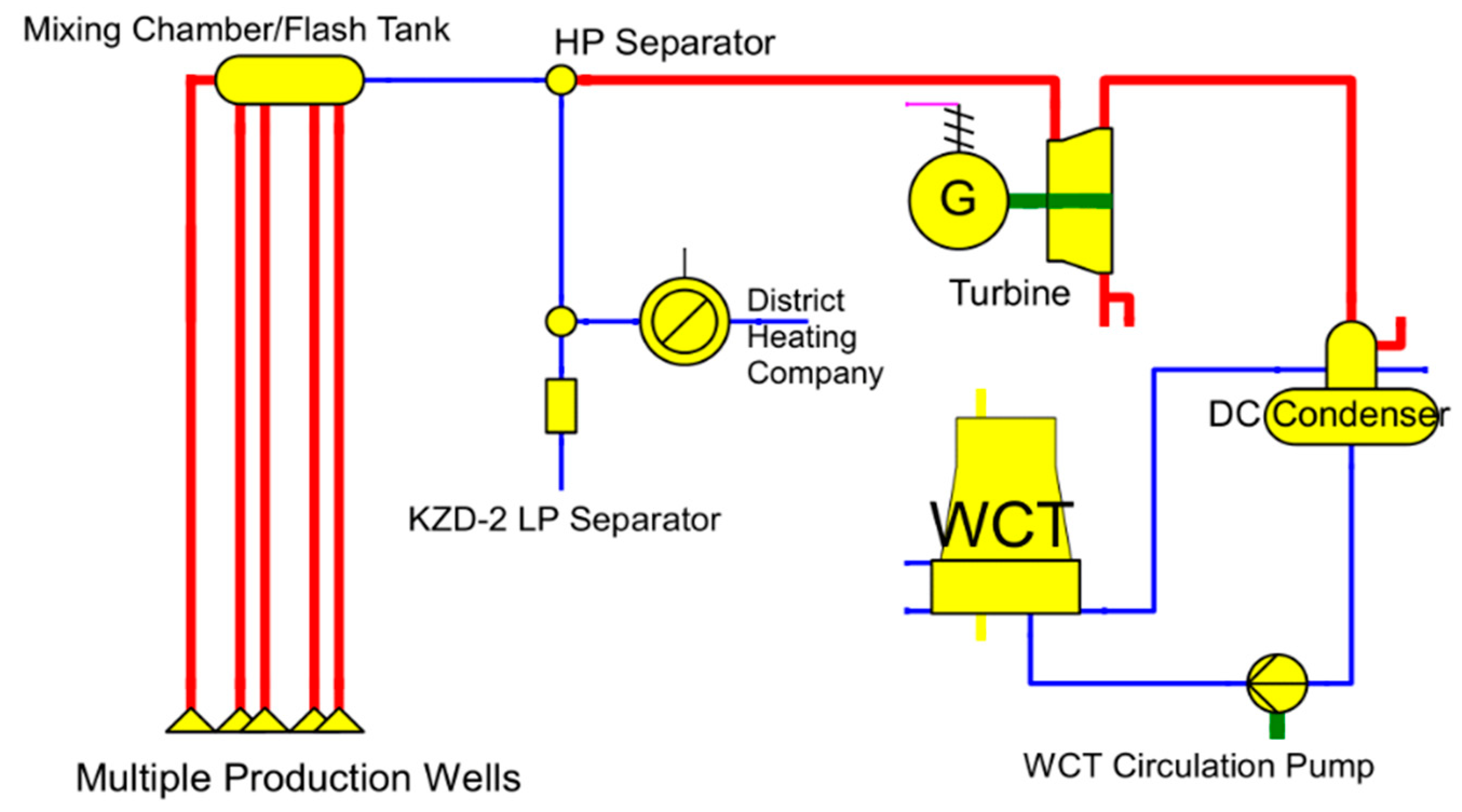
2.1.1. Existing Conditions of KZD-1 GEPP
2.1.2. Biomass Fuel Source
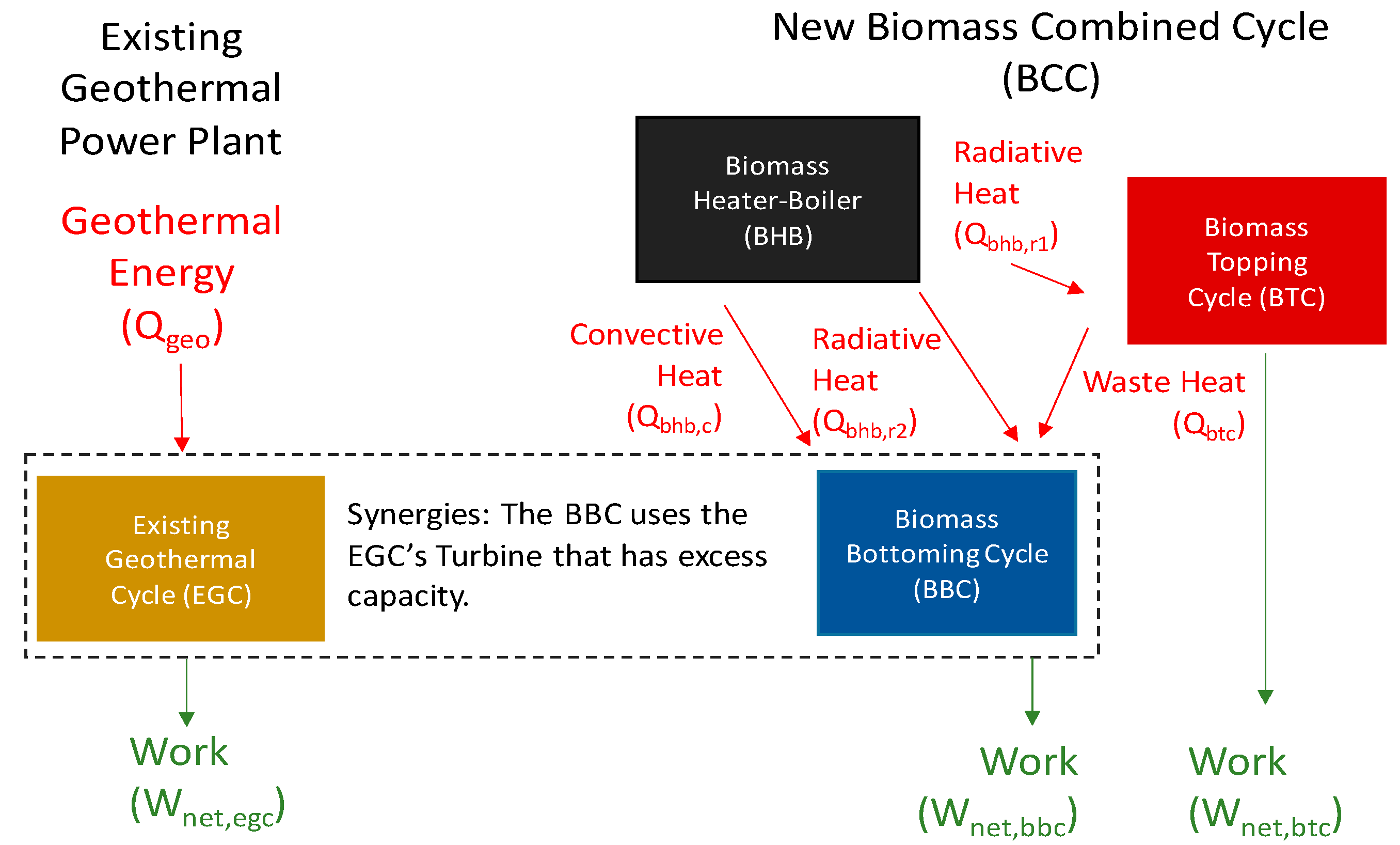
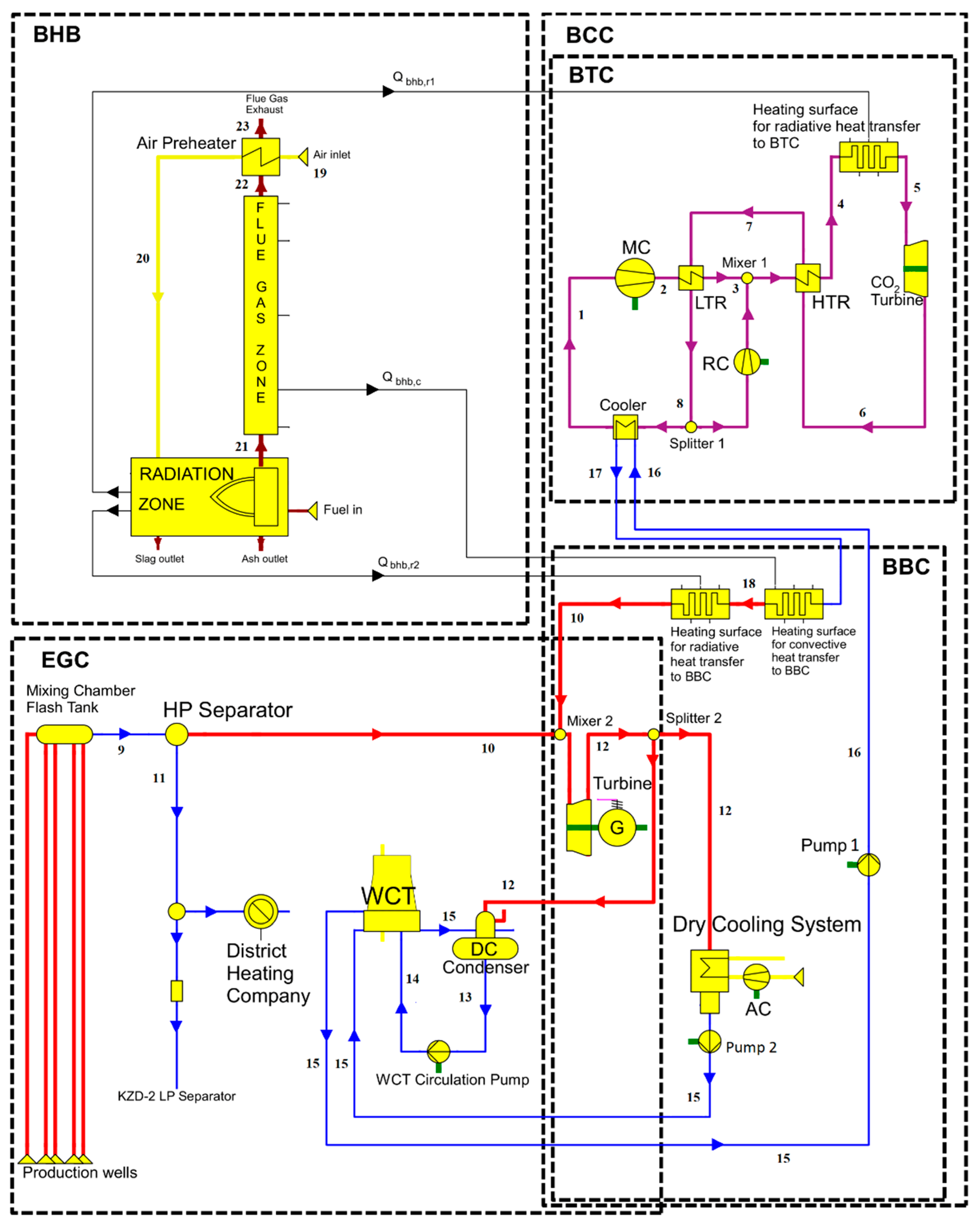
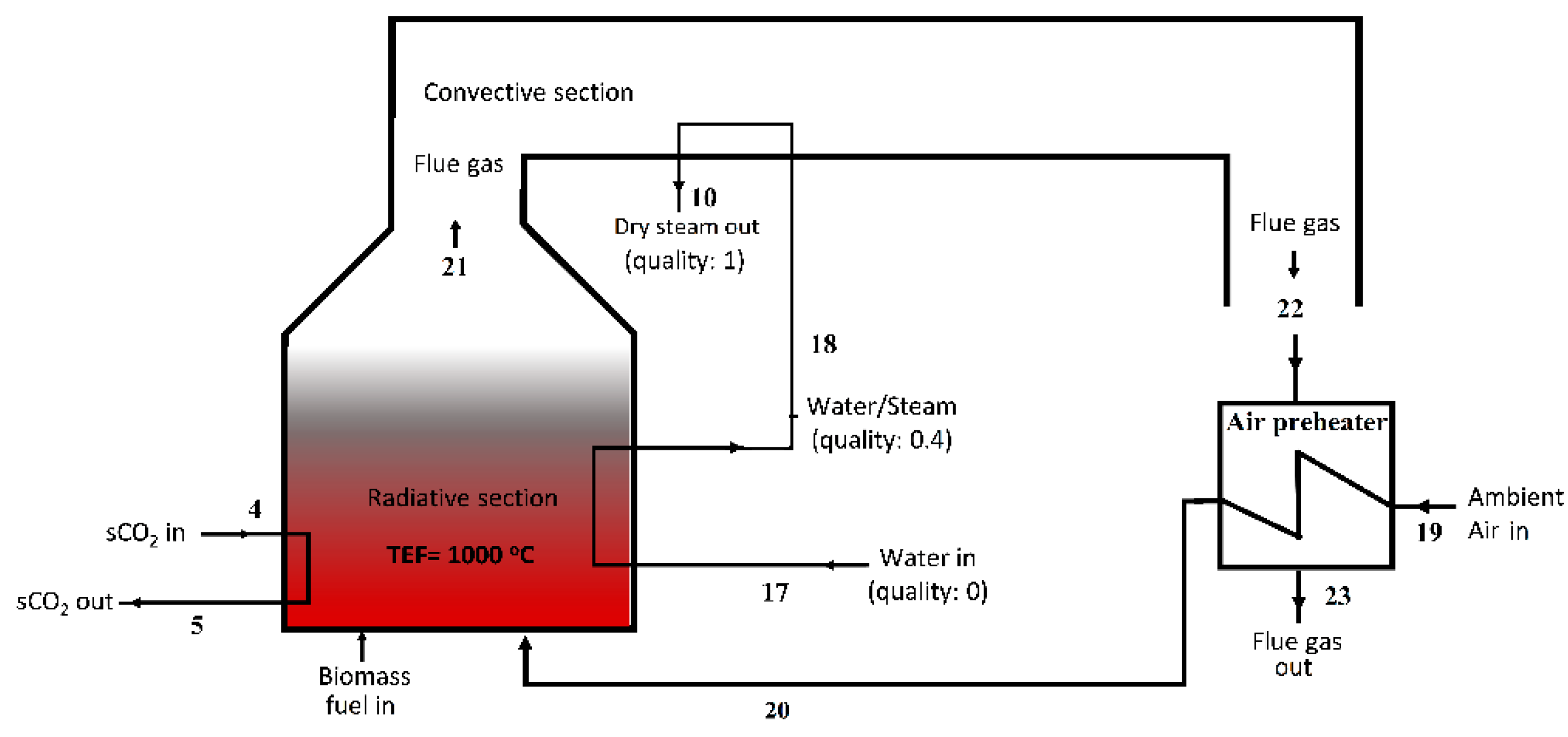
2.1.3. Model Development
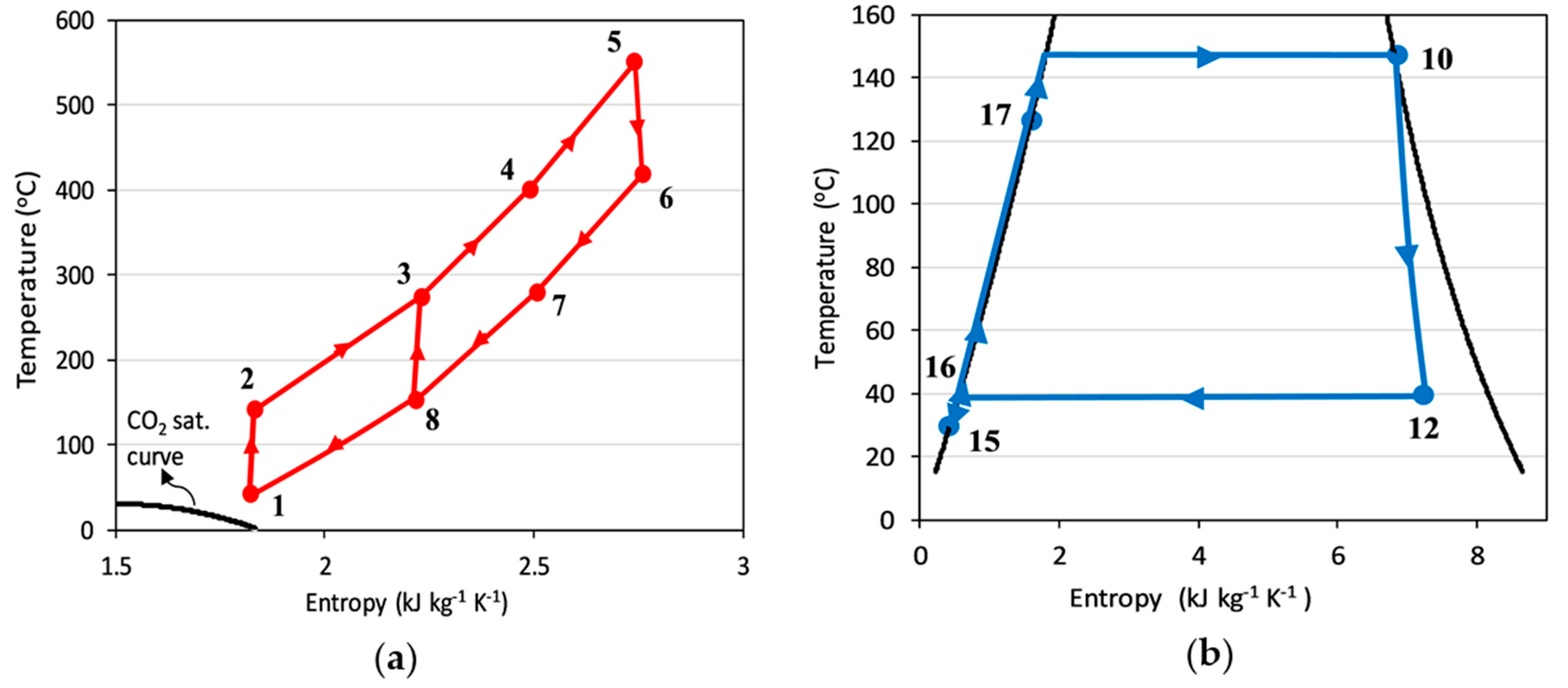
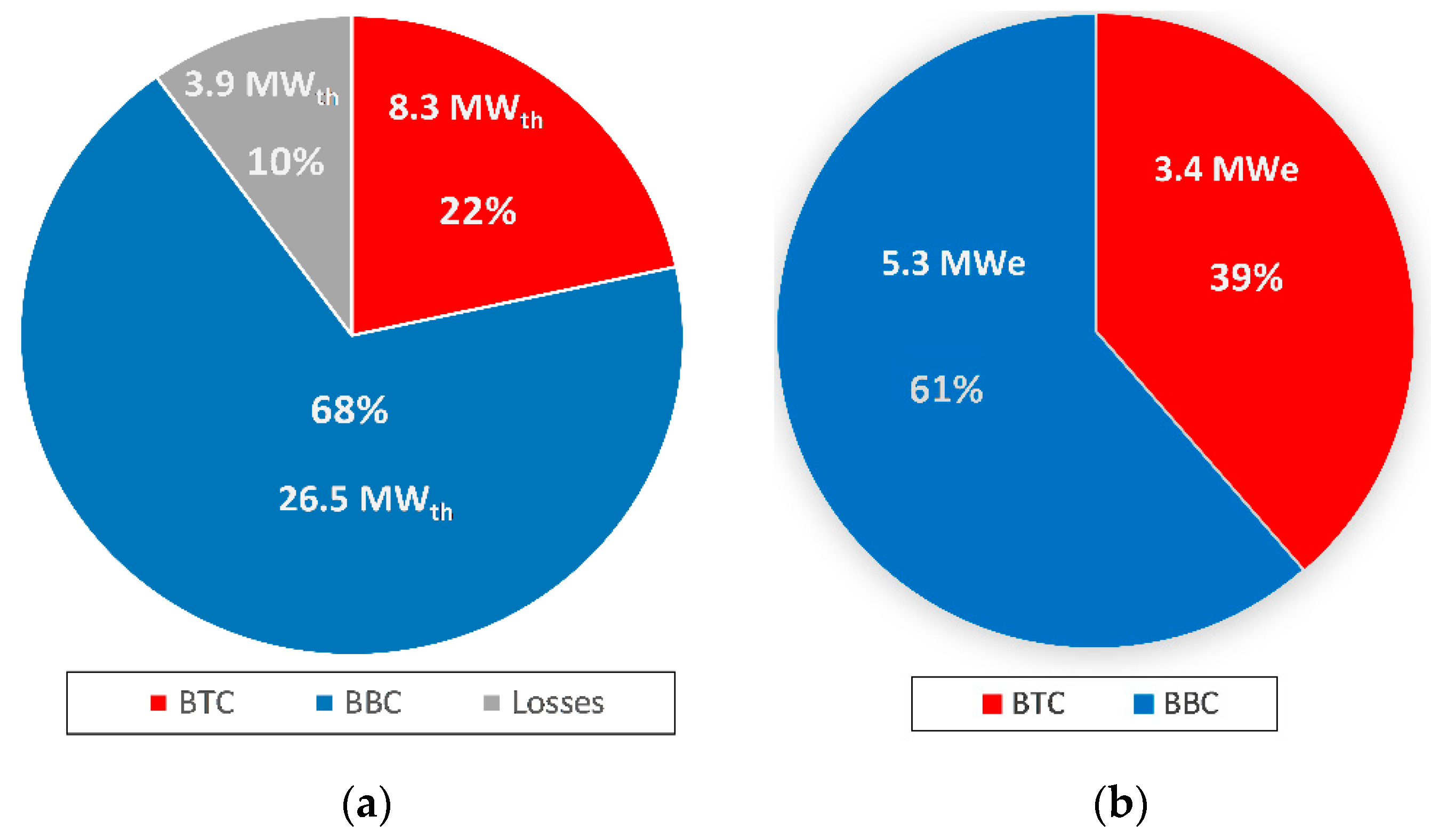
- BTC: Biomass combustion driven sCO2 Topping Cycle;
- BBC: Bottoming Biomass combustion and topping cycle waste, heat-driven steam Rankine Cycle;
- EGC: Existing open-loop steam Rankine cycle, driven by geothermal energy (EGC).
2.1.4. Energy Analysis
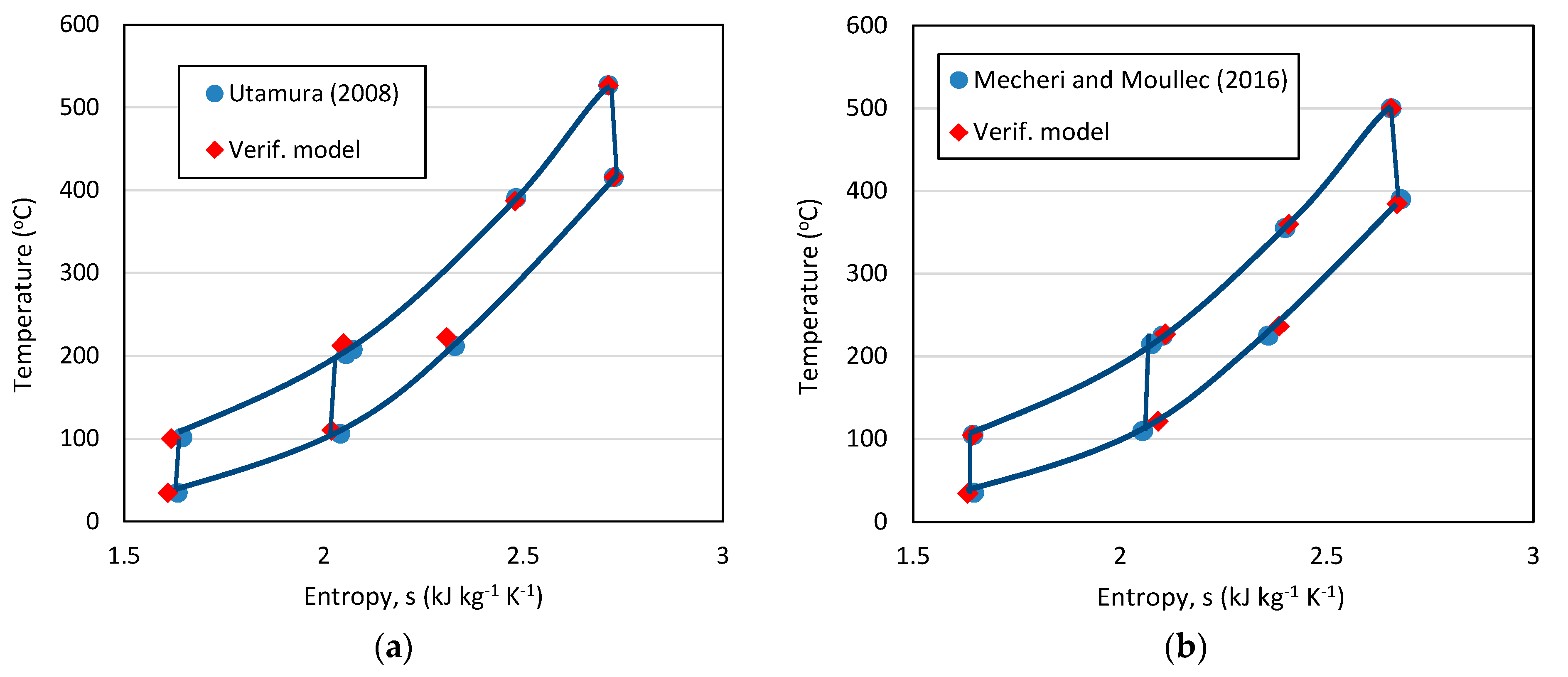
2.1.5. Model Verification
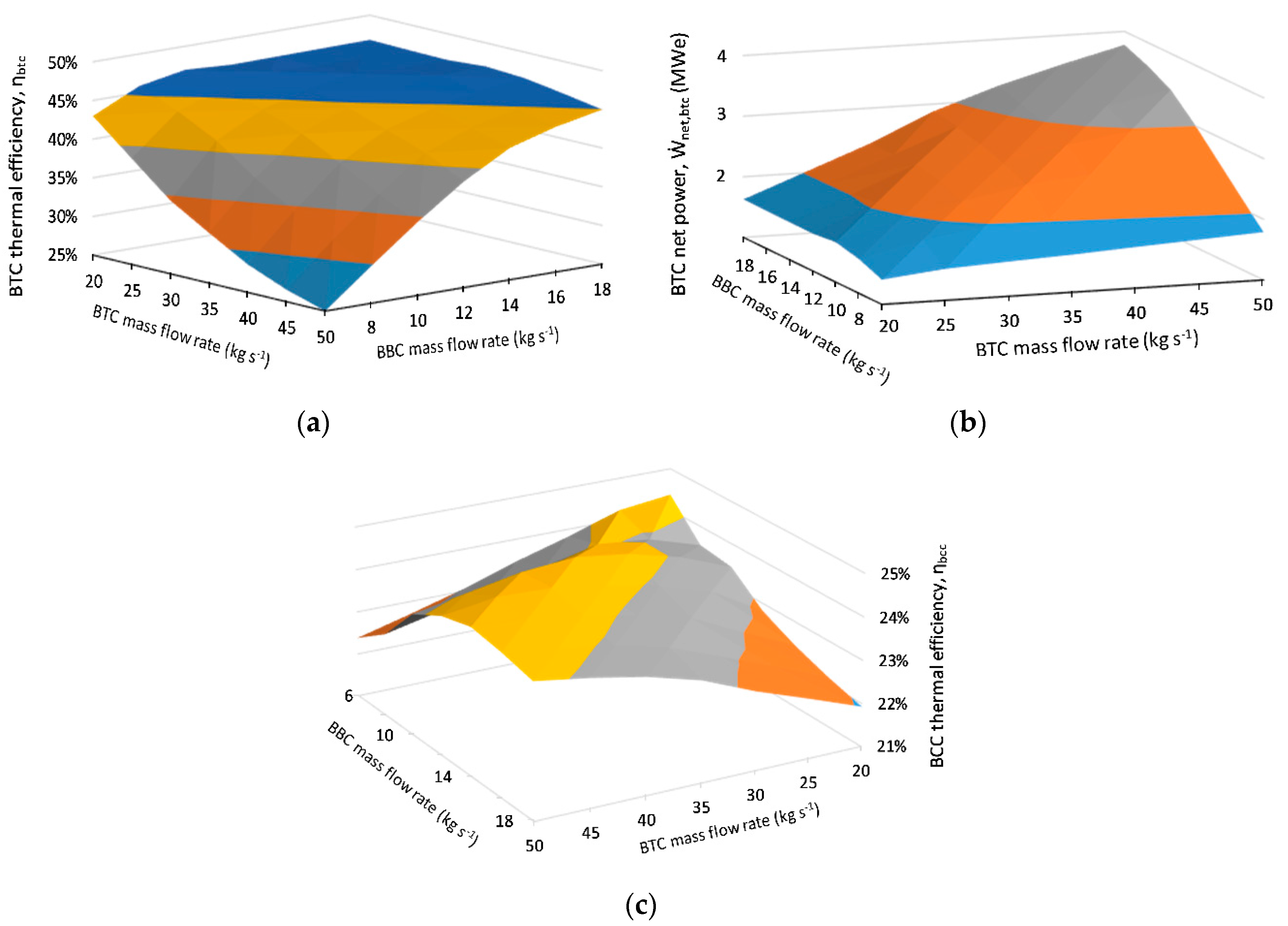
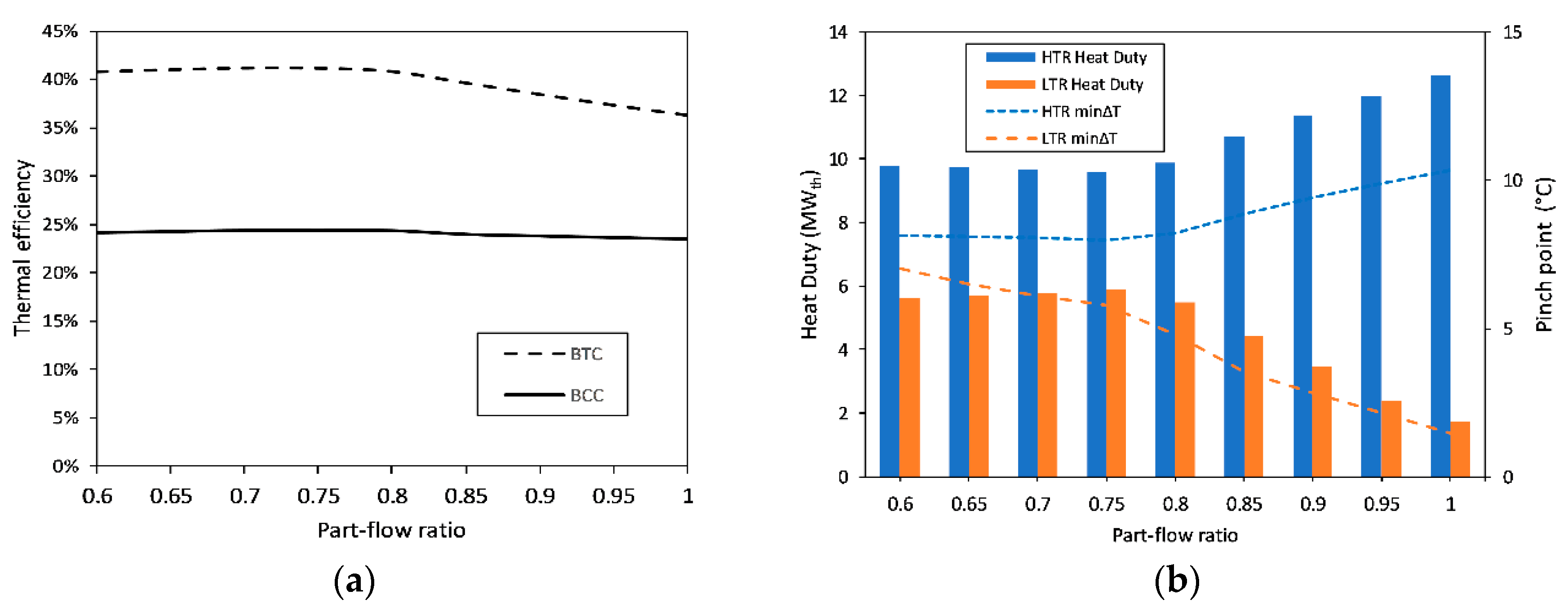
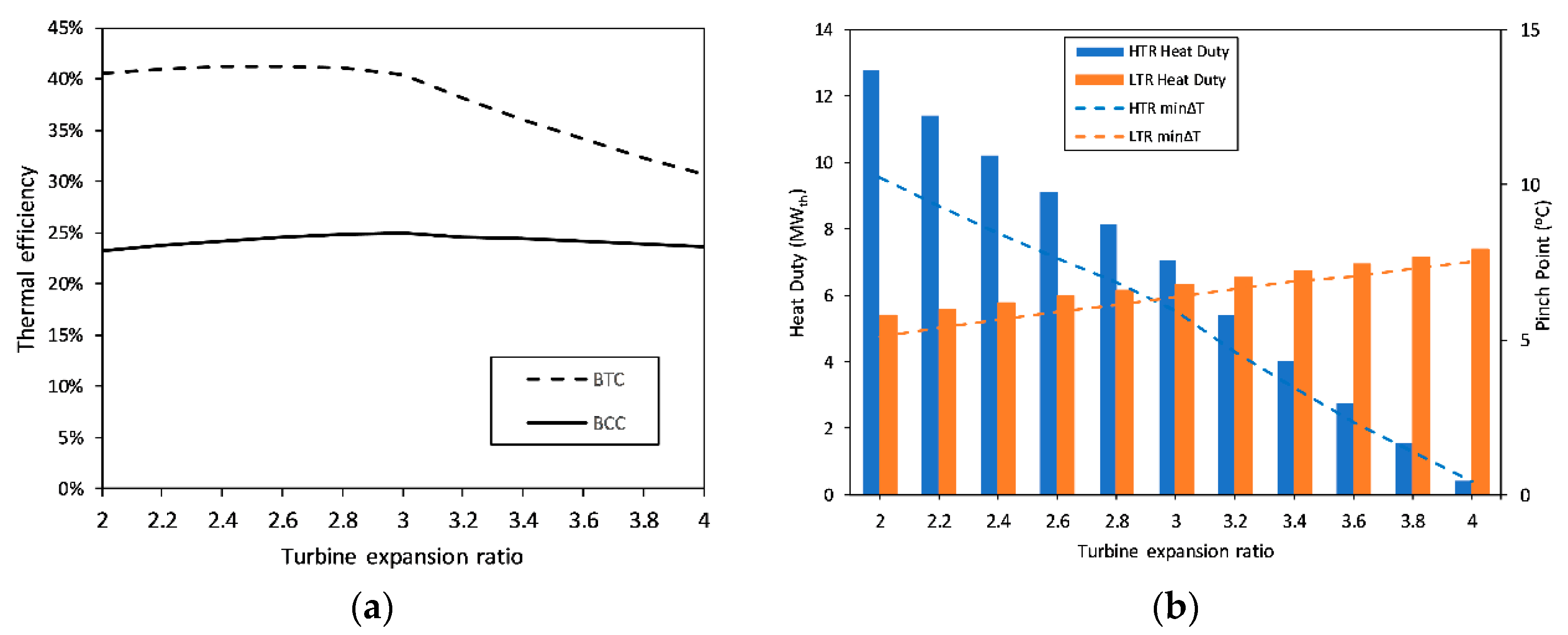
2.1.6. Optimization of Input Parameters
3. Results and Discussion
4. Conclusions
Author Contributions
Funding
Data Availability Statement
Acknowledgments
Conflicts of Interest
Abbreviations/Nomenclature
| b2e | biomass to electricity |
| BBC | biomass bottoming cycle |
| BCC | biomass combined cycle |
| BHB | biomass heater boiler |
| BTC | biomass topping cycle |
| CSP | concentrated solar power |
| DC | direct contact |
| DSG | direct steam generation |
| EGS | enhanced geothermal system |
| GEPP | geothermal electric power plant |
| HHV | higher heating value |
| HP | lower heating value |
| HTR | High-temperature recuperator |
| KZD-1 | Kızıldere-1 |
| KZD-2 | Kızıldere-2 |
| LCOE | levelized cost of electricity |
| LHV | lower heating value |
| LP | low pressure |
| LTR | Low-temperature recuperator |
| MC | main compressor |
| NGC | non-condensable gas |
| OR | olive residue |
| ORC | organic Rankine cycle |
| PTC | parabolic trough collector |
| PV | photovoltaic |
| RC | recompressor |
| sCO2 | supercritical CO2 |
| TAF | adiabatic flame temperature |
| tCO2 | transcritical CO2 |
| TEF | effective temperature of radiation |
| TIT | turbine inlet temperature |
| WCT | wet cooling tower |
| WHR | waste heat recovery |
| λ | excess air ratio |
References
- Wendt, D.S.; Mines, G.L. Use of a geothermal-solar retrofit hybrid power plant to mitigate declines in geothermal resource productivity. Trans. Geotherm. Resour. Counc. 2014, 38, 825–832. [Google Scholar]
- Michaelides, E.E.; Michaelides, D.N. The effect of ambient temperature fluctuation on the performance of geothermal power plants. Int. J. Exergy 2011, 8, 86–98. [Google Scholar] [CrossRef]
- Pasqualetti, M.J. The site specific nature of geothermal energy: The primary role of land use planning in nonelectric development. Nat. Resour. J. 1983, 23, 795–814. [Google Scholar]
- Borsukiewicz-Gozdur, A. Dual-fluid-hybrid power plant co-powered by low-temperature geothermal water. Geothermics 2010, 39, 170–176. [Google Scholar] [CrossRef]
- Briola, S.; Gabbrielli, R.; Bischi, A. Off-design performance analysis of a novel hybrid binary geothermal-biomass power plant in extreme environmental conditions. Energy Convers. Manag. 2019, 195, 210–225. [Google Scholar] [CrossRef]
- Rostamzadeh, H.; Gargari, S.G.; Namin, A.S.; Ghaebi, H. A novel multigeneration system driven by a hybrid biogas-geothermal heat source, Part II: Multi-criteria optimization. Energy Convers. Manag. 2019, 180, 859–888. [Google Scholar] [CrossRef]
- Di Pippo, R. Geothermal Power Generation: Developments and Innovation; Woodhead Publishing: Sawston, UK, 2016; ISBN 9780081003442. [Google Scholar]
- Li, K.; Liu, C.; Jiang, S.; Chen, Y. Review on hybrid geothermal and solar power systems. J. Clean. Prod. 2020, 250, 119481. [Google Scholar] [CrossRef]
- Lentz, Á.; Almanza, R. Solar-geothermal hybrid system. Appl. Therm. Eng. 2006, 26, 1537–1544. [Google Scholar] [CrossRef]
- Lentz, Á.; Almanza, R. Parabolic troughs to increase the geothermal wells flow enthalpy. Sol. Energy 2006, 80, 1290–1295. [Google Scholar] [CrossRef]
- Mir, I.; Escobar, R.; Vergara, J.; Bertrand, J. Performance Analysis of a Hybrid Solar-Geothermal Power Plant in Northern Chile. In Proceedings of the World Renewable Energy Congress-Sweden, Linköping, Sweden, 8–13 May 2011; pp. 1281–1288. [Google Scholar] [CrossRef] [Green Version]
- Cardemil, J.M.; Cortés, F.; Díaz, A.; Escobar, R. Thermodynamic evaluation of solar-geothermal hybrid power plants in northern Chile. Energy Convers. Manag. 2016, 123, 348–361. [Google Scholar] [CrossRef]
- McTigue, J.D.; Castro, J.; Mungas, G.; Kramer, N.; King, J.; Turchi, C.; Zhu, G. Hybridizing a geothermal power plant with concentrating solar power and thermal storage to increase power generation and dispatchability. Appl. Energy 2018, 228, 1837–1852. [Google Scholar] [CrossRef]
- Bonyadi, N.; Johnson, E.; Baker, D. Technoeconomic and exergy analysis of a solar geothermal hybrid electric power plant using a novel combined cycle. Energy Convers. Manag. 2018, 156, 542–554. [Google Scholar] [CrossRef]
- Jiang, P.X.; Zhang, F.Z.; Xu, R.N. Thermodynamic analysis of a solar–enhanced geothermal hybrid power plant using CO2 as working fluid. Appl. Therm. Eng. 2017, 116, 463–472. [Google Scholar] [CrossRef]
- Conboy, T.; Wright, S.; Pasch, J.; Fleming, D.; Rochau, G.; Fuller, R. Performance characteristics of an operating supercritical CO2 brayton cycle. J. Eng. Gas Turbines Power 2012, 134, 1–12. [Google Scholar] [CrossRef]
- Conboy, T.; Pasch, J.; Fleming, D. Control of a supercritical CO2 recompression brayton cycle demonstration loop. J. Eng. Gas Turbines Power 2013, 135, 1–12. [Google Scholar] [CrossRef]
- Angelino, G. Carbon dioxide condensation cycles for power production. J. Eng. Gas Turbines Power 1968, 90, 287–295. [Google Scholar] [CrossRef]
- Utamura, M.; Hasuike, H.; Ogawa, K.; Yamamoto, T.; Fukushima, T.; Watanabe, T.; Himeno, T. Demonstration of Supercritical CO2 Closed Regenerative Brayton Cycle in a Bench Scale Experiment. In Proceedings of the ASME Turbo Expo 2012: Turbine Technical Conference and Exposition, Copenhagen, Denmark, 11–15 June 2012; pp. 1–10. [Google Scholar]
- Turchi, C.S.; Ma, Z.; Dyreby, J. Supercritical carbon dioxide power cycle configurations for use in concentrating solar power systems. In Proceedings of the ASME Turbo Expo 2012: Turbine Technical Conference and Exposition, Copenhagen, Denmark, 11–15 June 2012; Volume 5, pp. 967–973. [Google Scholar] [CrossRef]
- Utamura, M. Thermodynamic analysis of part-flow cycle supercritical CO2 gas turbines. In Proceedings of the ASME Turbo Expo 2008: Power for Land, Sea, and Air, Berlin, Germany, 9–13 June 2008; Volume 2, pp. 423–430. [Google Scholar] [CrossRef]
- Crespi, F.; Gavagnin, G.; Sánchez, D.; Martínez, G.S. Supercritical carbon dioxide cycles for power generation: A review. Appl. Energy 2017, 195, 152–183. [Google Scholar] [CrossRef]
- Wang, X.; Wu, Y.; Wang, J.; Dai, Y. Thermo-economic Analysis of a Recompression sCO2 Cycle Combined with a tCO2 Cycle. In Proceedings of the ASME Turbo Expo 2015: Turbine Technical Conference and Exposition, Montreal, QC, Canada, 15–19 June 2015; pp. 1–11. [Google Scholar]
- Wang, X.; Wang, J.; Zhao, P.; Dai, Y. Thermodynamic Comparison and Optimization of Supercritical CO2 Brayton Cycles with a Bottoming Transcritical CO2 Cycle. J. Energy Eng. 2016, 142. [Google Scholar] [CrossRef]
- Wu, C.; Yan, X.J.; Wang, S.; Bai, K.L.; Di, J.; Cheng, S.F.; Li, J. System optimisation and performance analysis of CO2 transcritical power cycle for waste heat recovery. Energy 2016, 100, 391–400. [Google Scholar] [CrossRef]
- Besarati, S.M.; Goswami, D.Y. Analysis of Advanced Supercritical Carbon Dioxide Power Cycles With a Bottoming Cycle for Concentrating Solar Power Applications. J. Sol. Energy Eng. 2014, 136, 1–7. [Google Scholar] [CrossRef]
- Zhang, H.; Shao, S.; Zhao, H.; Feng, Z. Gt2014-26500 Thermodynamic Analysis of a Sco2 Part-Flow Cycle Combined with Liquefied Natural Gas as Heat Sink. In Proceedings of the ASME Turbo Expo 2014: Turbine Technical Conference and Exposition, Düsseldorf, Germany, 16–20 June 2014; pp. 1–8. [Google Scholar]
- Wang, X.; Dai, Y. Exergoeconomic analysis of utilizing the transcritical CO2 cycle and the ORC for a recompression supercritical CO2 cycle waste heat recovery: A comparative study. Appl. Energy 2016, 170, 193–207. [Google Scholar] [CrossRef]
- Akbari, A.D.; Mahmoudi, S.M.S. Thermoeconomic analysis & optimization of the combined supercritical CO2 (carbon dioxide) recompression Brayton/organic Rankine cycle. Energy 2014, 78, 501–512. [Google Scholar] [CrossRef]
- Le Moullec, Y. Conceptual study of a high efficiency coal-fired power plant with CO2 capture using a supercritical CO2 Brayton cycle. Energy 2013, 49, 32–46. [Google Scholar] [CrossRef]
- Mecheri, M.; Le Moullec, Y. Supercritical CO2 Brayton cycles for coal-fired power plants. Energy 2016, 103, 758–771. [Google Scholar] [CrossRef]
- Manente, G.; Lazzaretto, A. Innovative biomass to power conversion systems based on cascaded supercritical CO2 Brayton cycles. Biomass Bioenergy 2014, 69, 155–168. [Google Scholar] [CrossRef]
- Di Pippo, R. Geothermal Power Plants; Butterworth-Heinemann: Oxford, UK, 2012; Volume 7, ISBN 9780080878737. [Google Scholar]
- Gokcen, G.; Ozturk, H.K.; Hepbasli, A. Overview of Kizildere Geothermal Power Plant in Turkey. Energy Convers. Manag. 2004, 45, 83–98. [Google Scholar] [CrossRef] [Green Version]
- The Turkish Olive Oil Sector. Available online: https://www.olioofficina.it/en/knowledge/economy/the-turkish-olive-685oil-sector.htm (accessed on 15 April 2021).
- Hocaoğlu, S.M.; Haksevenler, H.G.; Baştürk, İ.; Aydöner, C. Zeytin Sektörü Atıklarının Yönetimi Projesi Nihai Rapor; Ministry of Environment and Urbanisation of Turkey: Ankara, Turkey, 2015. Available online: https://webdosya.csb.gov.tr/db/destek/icerikler/zeyt-n_sektoru_at-klar-n-n_yonet-m-_projes--20191127122437.pdf (accessed on 8 June 2021).
- Sheng, C.; Azevedo, J.L.T. Estimating the higher heating value of biomass fuels from basic analysis data. Biomass Bioenergy 2005, 28, 499–507. [Google Scholar] [CrossRef]
- Magalhães, D.; Kazanç, F.; Riaza, J.; Erensoy, S.; Kabaklı, Ö.; Chalmers, H. Combustion of Turkish lignites and olive residue: Experiments and kinetic modelling. Fuel 2017, 203, 868–876. [Google Scholar] [CrossRef]
- Vesely, L.; Dostal, V.; Hajek, P. Design of Experimental Loop With Supercritical Carbon Dioxide. In Proceedings of the 2014 22nd International Conference on Nuclear Engineering, Prague, Czech Republic, 7–11 July 2014; pp. 1–7. [Google Scholar] [CrossRef]
- Wang, X.; Liu, Q.; Bai, Z.; Lei, J.; Jin, H. Thermodynamic Analysis of the Cascaded Supercritical CO2 Cycle Integrated with Solar and Biomass Energy. Energy Procedia 2017, 105, 445–452. [Google Scholar] [CrossRef]
- Sun, E.; Xu, J.; Li, M.; Li, H.; Liu, C.; Xie, J. Synergetics: The cooperative phenomenon in multi-compressions S-CO2 power cycles. Energy Convers. Manag. X 2020, 7, 100042. [Google Scholar] [CrossRef]
- Turchi, C.S.; Ma, Z.; Neises, T.; Wagner, M. Thermodynamic Study of Advanced Supercritical Carbon Dioxide Power Cycles for High Performance Concentrating Solar Power Systems. In Proceedings of the ASME 2012 6th International Conference on Energy Sustainability collocated with the ASME 2012 10th International Conference on Fuel Cell Science, Engineering and Technology, San Diego, CA, USA, 23–26 July 2012; pp. 375–383. [Google Scholar] [CrossRef]
- Siddiqui, M.E.; Almitani, K.H. Energy analysis of the S-CO2 Brayton cycle with improved heat regeneration. Processes 2019, 7, 3. [Google Scholar] [CrossRef] [Green Version]
- Neises, T.; Turchi, C. A comparison of supercritical carbon dioxide power cycle configurations with an emphasis on CSP applications. Energy Procedia 2014, 49, 1187–1196. [Google Scholar] [CrossRef] [Green Version]
- Kulhánek, M.; Dostál, V. Thermodynamic Analysis and Comparison of Supercritical Carbon Dioxide Cycles. In Proceedings of the Supercritical CO2 Power Cycle Symposium, Boulder, Colorado, 24–25 May 2011; Available online: https://drive.google.com/file/d/1KcvMoLYNYXxxkbXjJWjSSixKQr4DVhmnHqAFQk-R3mybERAXd3TieAus5QmQ/view (accessed on 7 June 2021).
- Olumayegun, O.; Wang, M. Dynamic modelling and control of supercritical CO2 power cycle using waste heat from industrial processes. Fuel 2019, 249, 89–102. [Google Scholar] [CrossRef]
- Manente, G.; Fortuna, F.M. Supercritical CO2 power cycles for waste heat recovery: A systematic comparison between traditional and novel layouts with dual expansion. Energy Convers. Manag. 2019, 197, 111777. [Google Scholar] [CrossRef]
- Cabeza, L.F.; de Gracia, A.; Fernández, A.I.; Farid, M.M. Supercritical CO2 as heat transfer fluid: A review. Appl. Therm. Eng. 2017, 125, 799–810. [Google Scholar] [CrossRef] [Green Version]
- Strzalka, R.; Erhart, T.G.; Eicker, U. Analysis and optimization of a cogeneration system based on biomass combustion. Appl. Therm. Eng. 2013, 50, 1418–1426. [Google Scholar] [CrossRef]
- Stehlík, P.; Zagermann, S.; Gängler, T. Furnace integration into processes justified by detailed calculation using a simple mathematical model. Chem. Eng. Process. Process Intensif. 1995, 34, 9–23. [Google Scholar] [CrossRef]
- Zarrouk, S.J.; Moon, H. Efficiency of geothermal power plants: A worldwide review. Geothermics 2014, 51, 142–153. [Google Scholar] [CrossRef]
- Wright, S.A.; Davidson, C.S.; Scammell, W.O. Thermo-Economic Analysis of Four sCO2 Waste Heat Recovery Power Systems. In Proceedings of the Fifth International SCO2 Symposium, San Antonio, TX, USA, 29–31 March 2016; pp. 1–16. [Google Scholar]


| Parameter | |
|---|---|
| Proximate analysis (wt.%, dry basis) | |
| Volatile matter | 83.9 |
| Fixed Carbon a | 14.2 |
| Ash | 1.9 |
| Moisture content (wt.%, as received) | |
| Moisture | 7.5 |
| Ultimate analysis (wt.%, dry ash free) | |
| C | 51.5 |
| H | 6.2 |
| N | 0.7 |
| S | - |
| O a | 41.6 |
| Calorific value | |
| Higher heating value (dry basis) b (MJ kg−1) | 20.5 |
| Lower heating value (wet basis) c (MJ kg−1) | 17.5 |
| Input | Value | Unit | Description | Source/Comment |
|---|---|---|---|---|
| BTC | ||||
| ηcomp | 90 | % | Isentropic efficiency of the compressors | [21,32] |
| ηturb | 93 | % | Isentropic efficiency of the turbine | [21,31,44] |
| Tturb | 550 | °C | Turbine inlet temperature | [22,32,42,45] |
| Pturb | 20 | MPa | Turbine inlet pressure | [21] |
| φ | 3 | - | Expansion ratio of the CO2 turbine, P5/P6 | Optimized parameter [21]. |
| ψ | 0.75 | - | Part-flow ratio, ṁ1/ṁ8 | Optimized parameter [21]. |
| εrecup | 96 | % | Effectiveness of the recuperators | [21,39,46] |
| εcooler | 80 | % | Effectiveness of the cooler | [21,46] |
| ΔPhot,recup | 0.03 | MPa | Pressure drop at hot side of recuperators | [21,47] |
| ΔPcold,recup | 0.22 | MPa | Pressure drop at cold side of recuperators | [21,47] |
| ΔPhot,cooler | 0.6 | MPa | Pressure drop at hot side of cooler | [21,47] |
| ΔPcold,cooler | 0.1 | MPa | Pressure drop at cold side of cooler | [21,47] |
| ΔPbhb,co2 | 0.24 | MPa | Pressure drop for CO2 inside BHB | [21,47] |
| BBC | ||||
| ηturb,bot | 80 | % | Isentropic efficiency of the steam turbine | Assumption. See Section 2.1.1 |
| ηpump | 80 | % | Isentropic efficiency of the pumps | Generic value. |
| ηair comp | 90 | % | Isentropic efficiency of the air compressor | Generic value. |
| Tturb,bot | 146.9 | °C | Turbine inlet temperature | Operational KZD-1 data. |
| Pturb | 0.438 | MPa | Turbine inlet pressure | Operational KZD-1 data. |
| ΔPbhb,water | 0.01 | MPa | Pressure drop for water inside BHB | Generic value. |
| BHB | ||||
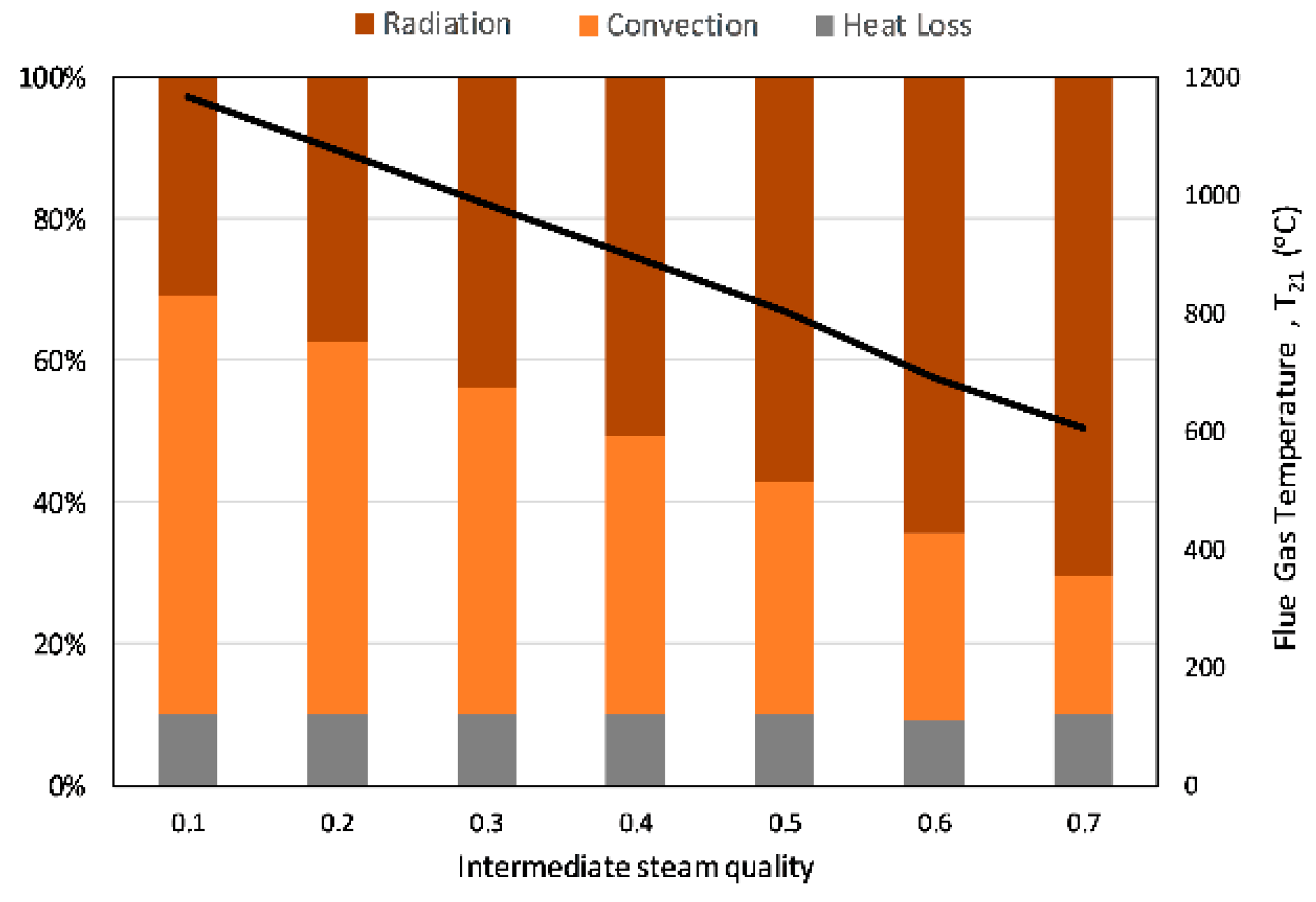
| λ | 1.5 | - | Excess air ratio | [32] |
| TEF | 1000 | °C | Effective temperature of radiation | [32] |
| Rad. loss | 5 | % | Heat loss in the radiative section of BHB | [32] |
| εair preheater | 80 | % | Effectiveness of the air preheater | [46] |
| Tair,in | 20 | °C | Air inlet temperature to air preheater | [32] |
| Inputs | Outputs | ||||||
|---|---|---|---|---|---|---|---|
| λ | Tair (°C) | Tflue gas (°C) | mflue gas (kg s−1) | XCO2 | XH2O | XN2 | XO2 |
| Manente and Lazzaretto [32] | |||||||
| 1.5 | 20 | 1405 | 8.225 | 0.1826 | 0.0754 | 0.6738 | 0.0682 |
| 100 | 1457 | ||||||
| 2.37 | 20 | 1000 | 12.41 | 0.1211 | 0.0499 | 0.7053 | 0.1237 |
| 2.56 | 100 | 1000 | 13.33 | 0.1127 | 0.0465 | 0.7095 | 0.1313 |
| Verification model | |||||||
| 1.5 | 20 | 1407 | 8.273 | 0.1820 | 0.0749 | 0.6752 | 0.0679 |
| 100 | 1458.6 | ||||||
| 2.37 | 20 | 999.9 | 12.49 | 0.1230 | 0.0496 | 0.7065 | 0.1209 |
| 2.56 | 100 | 1000.7 | 13.41 | 0.1125 | 0.0462 | 0.7107 | 0.1306 |
| Error: (Verif. Model—Ref.)/Ref. | |||||||
| 0.1% | 0.6% | –0.3% | –0.7% | 0.2% | –0.4% | ||
| 0.1% | |||||||
| 0.0% | 0.6% | 1.6% | –0.6% | 0.2% | –2.3% | ||
| 0.1% | 0.6% | –0.2% | –0.6% | 0.2% | –0.5% | ||
| Cycle | ṁ kg s−1 | ηth % | Ẇnet MWe |
|---|---|---|---|
| Topping part-flow sCO2 (BTC) Bottoming steam Rankine (BBC) | 45 | 40.1 | 3.4 |
| 12 | 16.9 | 5.3 | |
| Combined (BCC) | - | 24.9 | 8.7 |
| ηbhb | ṁfuel (kg s−1) | ṁflue gas (kg s−1) | TAF (°C) | T21 (°C) | XCO2 | XH2O | XN2 | XO2 |
|---|---|---|---|---|---|---|---|---|
| 0.90 | 2.2 | 21.5 | 1623 | 890.6 | 0.1775 | 0.0623 | 0.6909 | 0.0693 |
Publisher’s Note: MDPI stays neutral with regard to jurisdictional claims in published maps and institutional affiliations. |
© 2021 by the authors. Licensee MDPI, Basel, Switzerland. This article is an open access article distributed under the terms and conditions of the Creative Commons Attribution (CC BY) license (https://creativecommons.org/licenses/by/4.0/).
Share and Cite
Mutlu, B.; Baker, D.; Kazanç, F. Development and Analysis of the Novel Hybridization of a Single-Flash Geothermal Power Plant with Biomass Driven sCO2-Steam Rankine Combined Cycle. Entropy 2021, 23, 766. https://0-doi-org.brum.beds.ac.uk/10.3390/e23060766
Mutlu B, Baker D, Kazanç F. Development and Analysis of the Novel Hybridization of a Single-Flash Geothermal Power Plant with Biomass Driven sCO2-Steam Rankine Combined Cycle. Entropy. 2021; 23(6):766. https://0-doi-org.brum.beds.ac.uk/10.3390/e23060766
Chicago/Turabian StyleMutlu, Balkan, Derek Baker, and Feyza Kazanç. 2021. "Development and Analysis of the Novel Hybridization of a Single-Flash Geothermal Power Plant with Biomass Driven sCO2-Steam Rankine Combined Cycle" Entropy 23, no. 6: 766. https://0-doi-org.brum.beds.ac.uk/10.3390/e23060766