
Recent Progress on Biodegradable Tissue Engineering Scaffolds Prepared by Thermally-Induced Phase Separation (TIPS)


Abstract
:1. Introduction
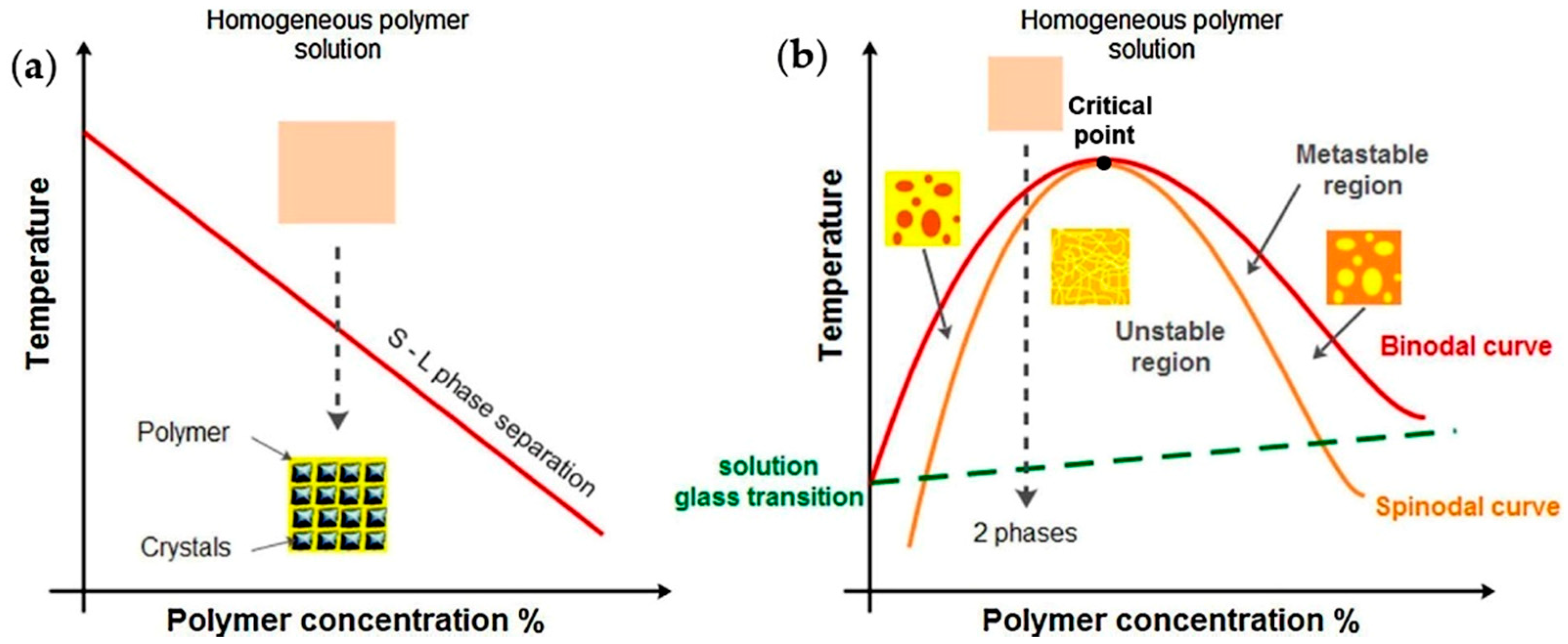
2. TIPS Technique
2.1. Methodology
2.2. Application of Foams Prepared by TIPS
3. TIPS and TIPS-Based Technologies for Fabrication of Tissue Engineering Scaffolds
3.1. Preparation of TE Scaffolds by the TIPS Technique
3.2. Preparation of TE Scaffolds by Combining TIPS with Other Technologies
3.2.1. Combination of TIPS and Porogen Leaching Technologies
3.2.2. Combination of TIPS and Electrospinning
3.2.3. Combination of TIPS and 3D Printing
3.2.4. Combination of TIPS and Textile Technology
4. Materials Used in Fabrication of Tissue Engineering Scaffolds by the TIPS Technique
4.1. Polymeric (Synthetic, Natural and Blended) Scaffolds
4.2. Composite (Natural/Synthetic Polymer-Ceramic) Scaffolds
5. Architectures Obtained through the Manipulation of the TIPS Process Conditions
5.1. Nanofibrous Structures Prepared by Liquid-Liquid Phase Separation
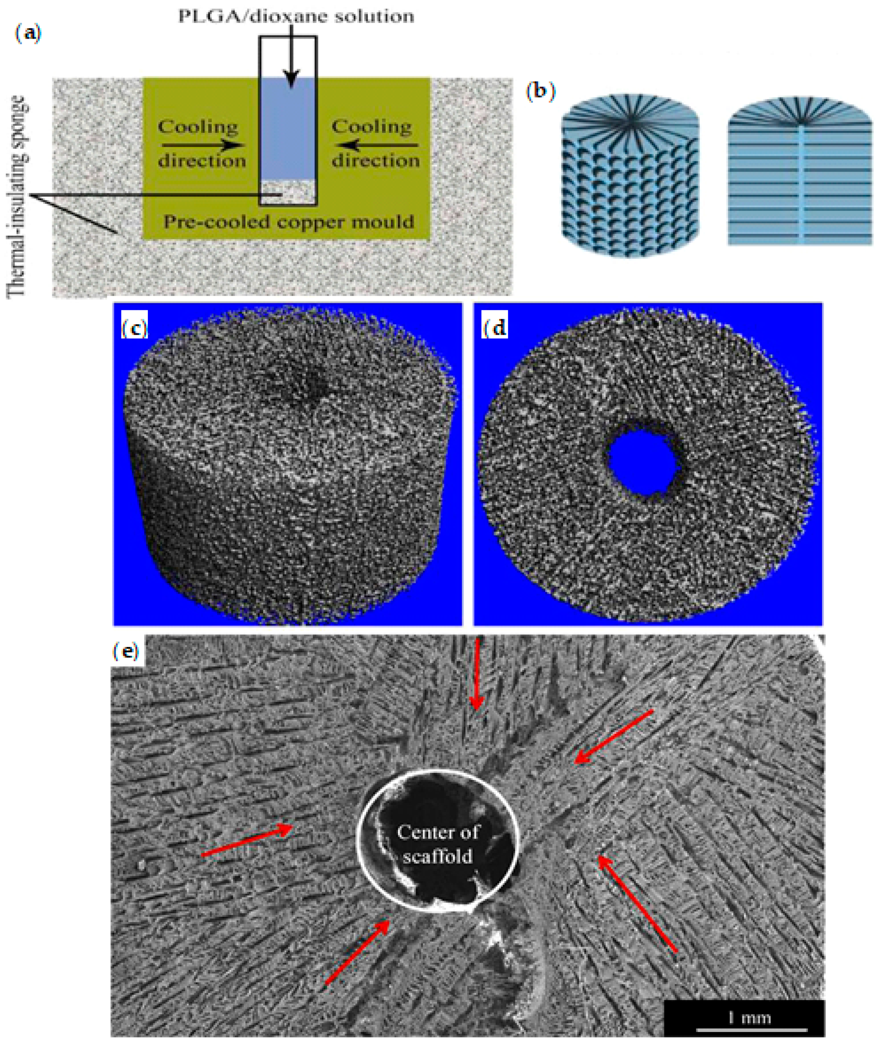
5.2. Anisotropic Structures Prepared by Solid-Liquid Phase Separation
5.3. Crystalline Structures Prepared by Crystallization Induced-Phase Separation
6. Conclusions
Author Contributions
Funding
Institutional Review Board Statement
Informed Consent Statement
Data Availability Statement
Conflicts of Interest
Abbreviations
| 3D | Three-dimensional |
| Alg | Alginate |
| AM | Additive manufacturing |
| β-TCP | Beta-tricalcium phosphate |
| BG | Bioactive glass |
| CaSi | Calcium silicate |
| CNC | Cellulose nanocrystals |
| Col | Collagen |
| Col1 | Collagen type 1 |
| CNFs | Carbon nanofibres |
| DCPD | Dicalcium phosphate dihydrate |
| DMF | Dimethylformamide |
| EAB | Ethyl alcohol bath |
| ECM | Extracellular matrix |
| EV | Exosome vesicle |
| FDA | Food and Drug Administration |
| FESEM | Field emission scanning electron microscope |
| GEL | Gelatin |
| GelMA | Gelatin methacryloyl |
| HAc | Hyaluronic acid |
| hAD-MSC | Human adipose mesenchymal stem cell |
| HA | Hydroxyapatite |
| HFIP | Hexafluoro-2-propanol |
| HSP | Hansen Solubility Parameters |
| LCA | Life Cycle Assessment |
| LD50 | Lethal dose |
| MicroCT | Micro-computed tomography |
| μFC | Micro-fluorcanasite |
| MSNs | Mesoporous silica nanoparticles |
| MWCNT | Multiwalled carbon nanotube |
| MSCs | Mesenchymal stem cells |
| NG | Nucleation and growth |
| NGC | Neural guidance channel |
| nHA | Nanohydroxyapatite |
| OA | Oleic acid |
| PANI | Polyaniline |
| PCL | Polycaprolactone |
| PDA | Polydopamine |
| PDLLA | Poly(d,l-lactide) |
| PDLLA-b-PBLG | Poly(d,l-lactide)-b-poly(γ-benzyl-l-glutamate) |
| PEG | Polyethylene glycol |
| PEI | Poly(ethylenimine) |
| PEEUU | Poly(urethane urea)ester |
| PGA | Polyglycolide |
| PGCL | Poly-(glycolide-co-caprolactone) |
| PHAA-g-PLLA | Poly(hydroxyalkyl methacrylate)-graft-poly(l-lactide) |
| PHB | Poly(3-hydroxybutyrate) |
| PHBV | Poly(3-hydroxybutyrate-co-3-hydroxyvalerate) |
| PLA | Polylactide |
| PLCL | Poly(lactide-co-caprolactone) |
| PLGA | Poly(lactide-co-glycolide) |
| PLLA | Poly(l-lactide) |
| PLLGC | Poly(l-lactide-co-glycolide-co-ɛ-caprolactone) |
| PTFE | Polytetrafluoroethylene |
| Qu | Quercetin |
| RBMSCs | Rabbit bone mesenchymal stem cells |
| SA | Salvianic acid |
| SC-CO2 | Supercritical carbon dioxide |
| SD | Spinodal decomposition |
| SEM | Scanning electron microscopy |
| TCH | Tetracycline hydrochloride |
| TCP | Tricalcium phosphate |
| TE | Tissue engineering |
| THF | Tetrahydrofuran |
| TIPS | Thermally-induced phase separation |
| TWB | Thermal water bath |
| UCST | Upper critical solution temperature |
References
- Martina, M.; Hutmacher, D.W. Biodegradable polymers applied in tissue engineering research: A review. Polym. Int. 2007, 56, 145–157. [Google Scholar] [CrossRef]
- Bacakova, L.; Zarubova, J.; Travnickova, M.; Musilkova, J.; Pajorova, J.; Slepicka, P.; Kasalkova, N.S.; Svorcik, V.; Kolska, Z.; Motarjemi, H.; et al. Stem cells: Their source, potency and use in regenerative therapies with focus on adipose-derived stem cells—A review. Biotechnol. Adv. 2018, 36, 1111–1126. [Google Scholar] [CrossRef] [PubMed]
- Hutmacher, D.W. Scaffolds in tissue engineering bone and cartilage. Biomaterials 2000, 21, 2529–2543. [Google Scholar] [CrossRef]
- Hollister, S.J. Porous scaffold design for tissue engineering. Nat. Mater. 2005, 4, 518–524. [Google Scholar] [CrossRef]
- Armentano, I.; Dottori, M.; Fortunati, E.; Mattioli, S.; Kenny, J.M. Biodegradable polymer matrix nanocomposites for tissue engineering: A review. Polym. Degrad. Stab. 2010, 95, 2126–2146. [Google Scholar] [CrossRef]
- Armentano, I.; Bitinis, N.; Fortunati, E.; Mattioli, S.; Rescignano, N.; Verdejo, R.; Lopez-Manchado, M.A.; Kenny, J.M. Multifunctional nanostructured PLA materials for packaging and tissue engineering. Prog. Polym. Sci. 2013, 38, 1720–1747. [Google Scholar] [CrossRef] [Green Version]
- Zeltinger, J.; Sherwood, J.K.; Graham, D.A.; Müeller, R.; Griffith, L.G. Effect of pore size and void fraction on cellular adhesion, proliferation, and matrix deposition. Tissue Eng. 2001, 7, 557–572. [Google Scholar] [CrossRef]
- Karageorgiou, V.; Kaplan, D. Porosity of 3D biomaterial scaffolds and osteogenesis. Biomaterials 2005, 26, 5474–5491. [Google Scholar] [CrossRef] [PubMed]
- Pellis, A.; Silvestrini, L.; Scaini, D.; Coburn, J.M.; Gardossi, L.; Kaplan, D.L.; Herrero Acero, E.; Guebitz, G.M. Enzyme-catalyzed functionalization of poly(L-lactic acid) for drug delivery applications. Process. Biochem. 2017, 59, 77–83. [Google Scholar] [CrossRef]
- Dorati, R.; DeTrizio, A.; Modena, T.; Conti, B.; Benazzo, F.; Gastaldi, G.; Genta, I. Biodegradable Scaffolds for Bone Regeneration Combined with Drug-Delivery Systems in Osteomyelitis Therapy. Pharmaceuticals 2017, 10, 96. [Google Scholar] [CrossRef] [Green Version]
- Biomaterials: Silk gland mimic spins strong fibres. Nature 2017, 541, 137. [CrossRef] [PubMed] [Green Version]
- Díaz, E.; Molpeceres, A.L.; Sandonis, I.; Puerto, I. PLLA/nHA Composite Films and Scaffolds for Medical Implants: In Vitro Degradation, Thermal and Mechanical Properties. J. Inorg. Organomet. Polym. Mater. 2019, 29, 121–131. [Google Scholar] [CrossRef]
- Guo, R.; Chen, S.; Xiao, X. Fabrication and characterization of poly (ethylenimine) modified poly (l-lactic acid) nanofibrous scaffolds. J. Biomater. Sci. Polym. Ed. 2019, 30, 1523–1541. [Google Scholar] [CrossRef] [PubMed]
- Onder, O.C.; Yilgor, E.; Yilgor, I. Critical parameters controlling the properties of monolithic poly(lactic acid) foams prepared by thermally induced phase separation. J. Polym. Sci. Part B Polym. Phys. 2019, 57, 98–108. [Google Scholar] [CrossRef]
- Bernardini, G.; Chellini, F.; Frediani, B.; Spreafico, A.; Santucci, A. Human platelet releasates combined with polyglycolic acid scaffold promote chondrocyte differentiation and phenotypic maintenance. J. Biosci. 2015, 40, 61–69. [Google Scholar] [CrossRef]
- Ding, J.; Chen, B.; Lv, T.; Liu, X.; Fu, X.; Wang, Q.; Yan, L.; Kang, N.; Cao, Y.; Xiao, R. Bone Marrow Mesenchymal Stem Cell-Based Engineered Cartilage Ameliorates Polyglycolic Acid/Polylactic Acid Scaffold-Induced Inflammation Through M2 Polarization of Macrophages in a Pig Model. Stem Cells Transl. Med. 2016, 5, 1079–1089. [Google Scholar] [CrossRef]
- Kumawat, V.S.; Ghosh, S.B.; Bandyopadhyay-Ghosh, S. Microporous biocomposite scaffolds with tunable degradation and interconnected microarchitecture-A synergistic integration of bioactive chain silicate glass-ceramic and poly(ε-caprolactone). Polym. Degrad. Stab. 2019, 165, 20–26. [Google Scholar] [CrossRef]
- Yao, Q.; Liu, Y.; Pan, Y.; Miszuk, J.M.; Sun, H. One-pot porogen free method fabricated porous microsphere-aggregated 3D PCL scaffolds for bone tissue engineering. J. Biomed. Mater. Res. B Appl. Biomater. 2020, 108, 2699–2710. [Google Scholar] [CrossRef]
- Díaz, E.; Puerto, I.; Sandonis, I.; Ribeiro, S.; Lanceros-Mendez, S. Hydrolytic degradation and cytotoxicity of poly(lactic-co-glycolic acid)/multiwalled carbon nanotubes for bone regeneration. J. Appl. Polym. Sci. 2020, 137, 48439. [Google Scholar] [CrossRef]
- McKenna, E.; Klein, T.J.; Doran, M.R.; Futrega, K. Integration of an ultra-strong poly(lactic-co-glycolic acid) (PLGA) knitted mesh into a thermally induced phase separation (TIPS) PLGA porous structure to yield a thin biphasic scaffold suitable for dermal tissue engineering. Biofabrication 2019, 12, 015015. [Google Scholar] [CrossRef] [Green Version]
- Liu, J.; Zhang, J.; James, P.F.; Yousefi, A.-M. I-Optimal design of poly(lactic-co-glycolic) acid/hydroxyapatite three-dimensional scaffolds produced by thermally induced phase separation. Polym. Eng. Sci. 2019, 59, 1146–1157. [Google Scholar] [CrossRef]
- Yousefi, A.-M.; Liu, J.; Sheppard, R.; Koo, S.; Silverstein, J.; Zhang, J.; James, P.F. I-Optimal Design of Hierarchical 3D Scaffolds Produced by Combining Additive Manufacturing and Thermally Induced Phase Separation. ACS Appl. Bio Mater. 2019, 2, 685–696. [Google Scholar] [CrossRef]
- He, Y.; Liu, W.; Guan, L.; Chen, J.; Duan, L.; Jia, Z.; Huang, J.; Li, W.; Liu, J.; Xiong, J.; et al. A 3D-Printed PLCL Scaffold Coated with Collagen Type I and Its Biocompatibility. BioMed Res. Int. 2018, 2018, 5147156. [Google Scholar] [CrossRef]
- Piao, H.; Kwon, J.-S.; Piao, S.; Sohn, J.-H.; Lee, Y.-S.; Bae, J.-W.; Hwang, K.-K.; Kim, D.-W.; Jeon, O.; Kim, B.-S.; et al. Effects of cardiac patches engineered with bone marrow-derived mononuclear cells and PGCL scaffolds in a rat myocardial infarction model. Biomaterials 2007, 28, 641–649. [Google Scholar] [CrossRef]
- Chen, P.; Zhou, Z.; Liu, W.; Zhao, Y.; Huang, T.; Li, X.; Duan, J.; Fang, J. Preparation and Characterization of Poly(L-lactide-co-glycolide-co-ε-caprolactone) Scaffolds by Thermally Induced Phase Separation. J. Macromol. Sci. B 2020, 59, 427–439. [Google Scholar] [CrossRef]
- Davachi, S.M.; Kaffashi, B. Polylactic Acid in Medicine. Polym.-Plast. Technol. Eng. 2015, 54, 944–967. [Google Scholar] [CrossRef]
- Ruiz-Hitzky, E.; Fernandes, F. Progress in Bionanocomposites: From green plastics to biomedical applications. Prog. Polym. Sci. 2013, 38, 1391. [Google Scholar] [CrossRef] [Green Version]
- Nie, L.; Chen, D.; Yang, Q.; Zou, P.; Feng, S.; Hu, H.; Suo, J. Hydroxyapatite/poly-l-lactide nanocomposites coating improves the adherence and proliferation of human bone mesenchymal stem cells on porous biphasic calcium phosphate scaffolds. Mater. Lett. 2013, 92, 25–28. [Google Scholar] [CrossRef]
- Roeder, R.K.; Converse, G.L.; Kane, R.J.; Yue, W. Hydroxyapatite-reinforced polymer biocomposites for synthetic bone substitutes. JOM 2008, 60, 38–45. [Google Scholar] [CrossRef]
- Wilberforce, S.I.J.; Finlayson, C.E.; Best, S.M.; Cameron, R.E. The influence of hydroxyapatite (HA) microparticles (m) and nanoparticles (n) on the thermal and dynamic mechanical properties of poly-l-lactide. Polymer 2011, 52, 2883–2890. [Google Scholar] [CrossRef]
- Davachi, S.M.; Kaffashi, B.; Torabinejad, B.; Zamanian, A.; Seyfi, J.; Hejazi, I. Investigating thermal, mechanical and rheological properties of novel antibacterial hybrid nanocomposites based on PLLA/triclosan/nano-hydroxyapatite. Polymer 2016, 90, 232–241. [Google Scholar] [CrossRef]
- Pietrasik, J.; Szustakiewicz, K.; Zaborski, M.; Haberko, K. Hydroxyapatite: An Environmentally Friendly Filler for Elastomers. Mol. Cryst. Liq. Cryst. 2008, 483, 172–178. [Google Scholar] [CrossRef]
- Hickey, D.J.; Ercan, B.; Sun, L.; Webster, T.J. Adding MgO nanoparticles to hydroxyapatite-PLLA nanocomposites for improved bone tissue engineering applications. Acta Biomater. 2015, 14, 175–184. [Google Scholar] [CrossRef] [PubMed]
- Marques, C.F.; Olhero, S.; Abrantes, J.C.C.; Marote, A.; Ferreira, S.; Vieira, S.I.; Ferreira, J.M.F. Biocompatibility and antimicrobial activity of biphasic calcium phosphate powders doped with metal ions for regenerative medicine. Ceram. Int. 2017, 43, 15719–15728. [Google Scholar] [CrossRef]
- Zhang, F.; Chang, J.; Lu, J.; Ning, C. Surface modification of beta-tricalcium phosphate scaffolds with topological nanoapatite coatings. Mater. Sci. Eng. C 2008, 28, 1330–1339. [Google Scholar] [CrossRef]
- Zhang, Q.; Zhou, Z.; Peng, C.; Huang, T.; Liu, W.; Liu, Q.; Zhou, H.; Wang, W.; Yan, H. Preparation and Properties of Novel Maleated Poly (D, L-lactide-co-glycolide) Porous Scaffolds for Tissue Engineering. J. Macromol. Sci. Part B Phys. 2017, 56, 505–515. [Google Scholar] [CrossRef]
- Duan, J.; Zhou, Z.; Huang, T.; Liu, W.; Zhao, Y.; Wu, W.; Li, X.; Fang, J. Biocompatibility properties of composite scaffolds based on 1,4-butanediamine modified poly(lactide-co-glycolide) and nanobioceramics. Int. J. Polym. Anal. Charact. 2019, 24, 428–438. [Google Scholar] [CrossRef]
- Whang, K.; Thomas, C.H.; Healy, K.E.; Nuber, G. A novel method to fabricate bioabsorbable scaffolds. Polymer 1995, 36, 837–842. [Google Scholar] [CrossRef]
- Sultana, N.; Wang, M. Fabrication of HA/PHBV composite scaffolds through the emulsion freezing/freeze-drying process and characterisation of the scaffolds. J. Mater. Sci. Mater. Med. 2008, 19, 2555–2561. [Google Scholar] [CrossRef]
- An, J.; Teoh, J.E.M.; Suntornnond, R.; Chua, C.K. Design and 3D Printing of Scaffolds and Tissues. Engineering 2015, 1, 261–268. [Google Scholar] [CrossRef] [Green Version]
- Ji, C.; Annabi, N.; Hosseinkhani, M.; Sivaloganathan, S.; Dehghani, F. Fabrication of poly-DL-lactide/polyethylene glycol scaffolds using the gas foaming technique. Acta Biomater. 2012, 8, 570–578. [Google Scholar] [CrossRef] [PubMed]
- Dehghani, F.; Annabi, N. Engineering porous scaffolds using gas-based techniques. Curr. Opin. Biotechnol. 2011, 22, 661–666. [Google Scholar] [CrossRef] [PubMed]
- Del Valle, L.; Franco, L.; Katsarava, R.; Puiggalí, J. Electrospun biodegradable polymers loaded with bactericide agents. AIMS Mol. Sci. 2016, 3, 52–87. [Google Scholar] [CrossRef] [Green Version]
- Llorens, E.; Armelin, E.; Pérez-Madrigal, M.; del Valle, L.; Alemán, C.; Puiggalí, J. Nanomembranes and Nanofibers from Biodegradable Conducting Polymers. Polymers 2013, 5, 1115–1157. [Google Scholar] [CrossRef] [Green Version]
- Del Valle, L.; Camps, R.; Díaz, A.; Franco, L.; Rodriguez-Galan, A.; Puiggalí, J. Electrospinning of polylactide and polycaprolactone mixtures for preparation of materials with tunable drug release properties. J. Polym. Res. 2011, 18, 1903–1917. [Google Scholar] [CrossRef]
- Zeinali, R.; Khorasani, M.T.; Behnamghader, A.; Atai, M.; Valle, L.; Puiggalí, J. Poly(hydroxybutyrate-co-hydroxyvalerate) Porous Matrices from Thermally Induced Phase Separation. Polymers 2020, 12, 2787. [Google Scholar] [CrossRef]
- Molladavoodi, S.; Gorbet, M.; Medley, J.; Ju Kwon, H. Investigation of microstructure, mechanical properties and cellular viability of poly(L-lactic acid) tissue engineering scaffolds prepared by different thermally induced phase separation protocols. J. Mech. Behav. Biomed. Mater. 2013, 17, 186–197. [Google Scholar] [CrossRef] [PubMed]
- Flaibani, M.; Elvassore, N. Gas anti-solvent precipitation assisted salt leaching for generation of micro- and nano-porous wall in bio-polymeric 3D scaffolds. Mater. Sci. Eng. C 2012, 32, 1632–1639. [Google Scholar] [CrossRef] [PubMed]
- Carfì Pavia, F.; Palumbo, F.S.; La Carrubba, V.; Bongiovì, F.; Brucato, V.; Pitarresi, G.; Giammona, G. Modulation of physical and biological properties of a composite PLLA and polyaspartamide derivative obtained via thermally induced phase separation (TIPS) technique. Mater. Sci. Eng. C 2016, 67, 561–569. [Google Scholar] [CrossRef] [Green Version]
- Akbarzadeh, R.; Yousefi, A.M. Effects of processing parameters in thermally induced phase separation technique on porous architecture of scaffolds for bone tissue engineering. J. Biomed. Mater. Res. B Appl. Biomater. 2014, 102, 1304–1315. [Google Scholar] [CrossRef]
- Lombardo, M.E.; Carfì Pavia, F.; Vitrano, I.; Ghersi, G.; Brucato, V.; Rosei, F.; La Carrubba, V. PLLA scaffolds with controlled architecture as potential microenvironment for in vitro tumor model. Tissue Cell 2019, 58, 33–41. [Google Scholar] [CrossRef]
- La Carrubba, V.; Pavia, F.C.; Brucato, V.; Piccarolo, S. PLLA/PLA scaffolds prepared via Thermally Induced Phase Separation (TIPS): Tuning of properties and biodegradability. Int. J. Mater. Form. 2008, 1, 619–622. [Google Scholar] [CrossRef]
- Schugens, C.; Maquet, V.; Grandfils, C.; Jerome, R.; Teyssie, P. Biodegradable and macroporous polylactide implants for cell transplantation: 1. Preparation of macroporous polylactide supports by solid-liquid phase separation. Polymer 1996, 37, 1027–1038. [Google Scholar] [CrossRef] [Green Version]
- Salehi, M.; Naseri-Nosar, M.; Ebrahimi-Barough, S.; Nourani, M.; Khojasteh, A.; Hamidieh, A.A.; Amani, A.; Farzamfar, S.; Ai, J. Sciatic nerve regeneration by transplantation of Schwann cells via erythropoietin controlled-releasing polylactic acid/multiwalled carbon nanotubes/gelatin nanofibrils neural guidance conduit. J. Biomed. Mater. Res. B Appl. Biomater. 2018, 106, 1463–1476. [Google Scholar] [CrossRef]
- Kasoju, N.; Kubies, D.; Sedlačík, T.; Janoušková, O.; Koubková, J.; Kumorek, M.M.; Rypáček, F. Polymer scaffolds with no skin-effect for tissue engineering applications fabricated by thermally induced phase separation. Biomed. Mater. 2016, 11, 015002. [Google Scholar] [CrossRef]
- Langford, C.R.; Cameron, N.R. Materials for Tissue Engineering and 3D Cell Culture. In Bio-Inspired Polymers; Bruns, N., Kilbinger, A.F.M., Eds.; The Royal Society of Chemistry: Cambridge, UK, 2017; pp. 460–489. [Google Scholar]
- Lou, T.; Wang, X.; Yan, X.; Miao, Y.; Long, Y.-Z.; Yin, H.-L.; Sun, B.; Song, G. Fabrication and biocompatibility of poly(l-lactic acid) and chitosan composite scaffolds with hierarchical microstructures. Mater. Sci. Eng. C 2016, 64, 341–345. [Google Scholar] [CrossRef]
- Guo, X.; Zhu, J.; Zhang, H.; You, Z.; Morsi, Y.; Mo, X.; Zhu, T. Facile preparation of a controlled-release tubular scaffold for blood vessel implantation. J. Colloid Interface Sci. 2019, 539, 351–360. [Google Scholar] [CrossRef]
- Farzamfar, S.; Salehi, M.; Tavangar, S.M.; Verdi, J.; Mansouri, K.; Ai, A.; Malekshahi, Z.V.; Ai, J. A novel polycaprolactone/carbon nanofiber composite as a conductive neural guidance channel: An in vitro and in vivo study. Prog. Biomater. 2019, 8, 239–248. [Google Scholar] [CrossRef] [Green Version]
- Szustakiewicz, K.; Gazińska, M.; Kryszak, B.; Grzymajło, M.; Pigłowski, J.; Wiglusz, R.J.; Okamoto, M. The influence of hydroxyapatite content on properties of poly(L-lactide)/hydroxyapatite porous scaffolds obtained using thermal induced phase separation technique. Eur. Polym. J. 2019, 113, 313–320. [Google Scholar] [CrossRef]
- Yao, Q.; Fuglsby, K.E.; Zheng, X.; Sun, H. Nanoclay-functionalized 3D nanofibrous scaffolds promote bone regeneration. J. Mater. Chem. B 2020, 8, 3842–3851. [Google Scholar] [CrossRef] [PubMed]
- Dai, Y.; Shen, T.; Ma, L.; Wang, D.; Gao, C. Regeneration of osteochondral defects in vivo by a cell-free cylindrical poly(lactide-co-glycolide) scaffold with a radially oriented microstructure. J. Tissue Eng. Regen. Med. 2018, 12, e1647–e1661. [Google Scholar] [CrossRef] [PubMed]
- Zhu, L.; Chen, S.; Liu, K.; Wen, W.; Lu, L.; Ding, S.; Zhou, C.; Luo, B. 3D poly (L-lactide)/chitosan micro/nano fibrous scaffolds functionalized with quercetin-polydopamine for enhanced osteogenic and anti-inflammatory activities. Chem. Eng. J. 2020, 391, 123524. [Google Scholar] [CrossRef]
- Gay, S.; Lefebvre, G.; Bonnin, M.; Nottelet, B.; Boury, F.; Gibaud, A.; Calvignac, B. PLA scaffolds production from Thermally Induced Phase Separation: Effect of process parameters and development of an environmentally improved route assisted by supercritical carbon dioxide. J. Supercrit. Fluids 2018, 136, 123–135. [Google Scholar] [CrossRef]
- Chen, J.-S.; Tu, S.-L.; Tsay, R.-Y. A morphological study of porous polylactide scaffolds prepared by thermally induced phase separation. J. Taiwan. Inst. Chem. Eng. 2010, 41, 229–238. [Google Scholar] [CrossRef]
- Wang, L.; Kang, Y.; Chen, S.; Mo, X.; Jiang, J.; Yan, X.; Zhu, T.; Zhao, J. Macroporous 3D Scaffold with Self-Fitting Capability for Effectively Repairing Massive Rotator Cuff Tear. ACS Biomater. Sci. Eng. 2020. [Google Scholar] [CrossRef]
- Chen, J.; Yu, M.; Guo, B.; Ma, P.X.; Yin, Z. Conductive nanofibrous composite scaffolds based on in-situ formed polyaniline nanoparticle and polylactide for bone regeneration. J. Colloid Interface Sci. 2018, 514, 517–527. [Google Scholar] [CrossRef]
- Zhang, C.; Dong, P.; Bai, Y.; Quan, D. Nanofibrous polyester-polypeptide block copolymer scaffolds with high porosity and controlled degradation promote cell adhesion, proliferation and differentiation. Eur. Polym. J. 2020, 130, 109647. [Google Scholar] [CrossRef]
- Gandolfi, M.G.; Zamparini, F.; Degli Esposti, M.; Chiellini, F.; Fava, F.; Fabbri, P.; Taddei, P.; Prati, C. Highly porous polycaprolactone scaffolds doped with calcium silicate and dicalcium phosphate dihydrate designed for bone regeneration. Mater. Sci. Eng. C 2019, 102, 341–361. [Google Scholar] [CrossRef] [PubMed]
- Farzamfar, S.; Naseri-Nosar, M.; Sahrapeyma, H.; Ehterami, A.; Goodarzi, A.; Rahmati, M.; Ahmadi Lakalayeh, G.; Ghorbani, S.; Vaez, A.; Salehi, M. Tetracycline hydrochloride-containing poly (ε-caprolactone)/poly lactic acid scaffold for bone tissue engineering application: In vitro and in vivo study. Int. J. Polym. Mater. Polym. Biomater. 2019, 68, 472–479. [Google Scholar] [CrossRef]
- Xu, C.; Okpokwasili, C.; Huang, Y.; Shi, X.; Wu, J.; Liao, J.; Tang, L.; Hong, Y. Optimizing Anisotropic Polyurethane Scaffolds to Mechanically Match with Native Myocardium. ACS Biomater. Sci. Eng. 2020, 6, 2757–2769. [Google Scholar] [CrossRef]
- Feng, X.; Xu, P.; Shen, T.; Zhang, Y.; Ye, J.; Gao, C. Influence of pore architectures of silk fibroin/collagen composite scaffolds on the regeneration of osteochondral defects in vivo. J. Mater. Chem. B 2020, 8, 391–405. [Google Scholar] [CrossRef]
- Bužarovska, A.; Dinescu, S.; Chitoiu, L.; Costache, M. Porous poly(L-lactic acid) nanocomposite scaffolds with functionalized TiO2 nanoparticles: Properties, cytocompatibility and drug release capability. J. Mater. Sci. 2018, 53, 11151–11166. [Google Scholar] [CrossRef]
- Montanheiro, T.L.d.A.; Montagna, L.S.; Patrulea, V.; Jordan, O.; Borchard, G.; Lobato, G.M.M.; Catalani, L.H.; Lemes, A.P. Evaluation of cellulose nanocrystal addition on morphology, compression modulus and cytotoxicity of poly(3-hydroxybutyrate-co-3-hydroxyvalerate) scaffolds. J. Mater. Sci. 2019, 54, 7198–7210. [Google Scholar] [CrossRef]
- Erickson, A.E.; Sun, J.; Lan Levengood, S.K.; Swanson, S.; Chang, F.-C.; Tsao, C.T.; Zhang, M. Chitosan-based composite bilayer scaffold as an in vitro osteochondral defect regeneration model. Biomed. Microdevices 2019, 21, 34. [Google Scholar] [CrossRef]
- Conoscenti, G.; Carfì Pavia, F.; Ongaro, A.; Brucato, V.; Goegele, C.; Schwarz, S.; Boccaccini, A.R.; Stoelzel, K.; La Carrubba, V.; Schulze-Tanzil, G. Human nasoseptal chondrocytes maintain their differentiated phenotype on PLLA scaffolds produced by thermally induced phase separation and supplemented with bioactive glass 1393. Connect. Tissue Res. 2019, 60, 344–357. [Google Scholar] [CrossRef]
- Degli Esposti, M.; Chiellini, F.; Bondioli, F.; Morselli, D.; Fabbri, P. Highly porous PHB-based bioactive scaffolds for bone tissue engineering by in situ synthesis of hydroxyapatite. Mater. Sci. Eng. C 2019, 100, 286–296. [Google Scholar] [CrossRef]
- Gandolfi, M.G.; Gardin, C.; Zamparini, F.; Ferroni, L.; Esposti, M.D.; Parchi, G.; Ercan, B.; Manzoli, L.; Fava, F.; Fabbri, P.; et al. Mineral-Doped Poly(L-lactide) Acid Scaffolds Enriched with Exosomes Improve Osteogenic Commitment of Human Adipose-Derived Mesenchymal Stem Cells. Nanomaterials 2020, 10, 432. [Google Scholar] [CrossRef] [Green Version]
- Si, J.; Yang, Y.; Xing, X.; Yang, F.; Shan, P. Controlled degradable chitosan/collagen composite scaffolds for application in nerve tissue regeneration. Polym. Degrad. Stab. 2019, 166, 73–85. [Google Scholar] [CrossRef]
- Salehi, M.; Farzamfar, S.; Bozorgzadeh, S.; Bastami, F. Fabrication of Poly(L-Lactic Acid)/Chitosan Scaffolds by Solid-Liquid Phase Separation Method for Nerve Tissue Engineering: An In Vitro Study on Human Neuroblasts. J. Craniofac. Surg. 2019, 30, 784–789. [Google Scholar] [CrossRef]
- Van de Witte, P.; Dijkstra, P.J.; van den Berg, J.W.A.; Feijen, J. Phase separation processes in polymer solutions in relation to membrane formation. J. Membr. Sci. 1996, 117, 1–31. [Google Scholar] [CrossRef] [Green Version]
- Auras, R.; Lim, L.-T.; Selke, S.; Tsuji, H. Poly(Lactic Acid): Synthesis, Structures, Properties, Processing, and Applications; John Wiley & Sons: Hoboken, NJ, USA, 2010. [Google Scholar]
- Chen, V.J.; Ma, P.X. Polymer phase separation. In Scaffolding in Tissue Engineering; Ma, P.X., Elisseeff, J., Eds.; Taylor & Francis: Boca Raton, FL, USA, 2006; pp. 125–137. [Google Scholar]
- Zhang, R.; Ma, P.X. Poly(α-hydroxyl acids)/hydroxyapatite porous composites for bone-tissue engineering. I. Preparation and morphology. J. Biomed. Mater. Res. 1999, 44, 446–455. [Google Scholar] [CrossRef]
- Ma, P.X.; Zhang, R. Microtubular architecture of biodegradable polymer scaffolds. J. Biomed. Mater. Res. 2001, 56, 469–477. [Google Scholar] [CrossRef] [Green Version]
- Schugens, C.; Maquet, V.; Grandfils, C.; Jerome, R.; Teyssie, P. Polylactide macroporous biodegradable implants for cell transplantation. II. Preparation of polylactide foams by liquid-liquid phase separation. J. Biomed. Mater. Res. 1996, 30, 449–461. [Google Scholar] [CrossRef]
- Nam, Y.S.; Park, T.G. Biodegradable polymeric microcellular foams by modified thermally induced phase separation method. Biomaterials 1999, 20, 1783–1790. [Google Scholar] [CrossRef]
- Flory, P.J. Principles of Polymer Chemistry; Cornell University Press: Ithaca, NY, USA, 1953; pp. 541–594. [Google Scholar]
- Lloyd, D.R.; Kim, S.S.; Kinzer, K.E. Microporous membrane formation via thermally-induced phase separation. II. Liquid—liquid phase separation. J. Membr. Sci. 1991, 64, 1–11. [Google Scholar] [CrossRef]
- Önder, Ö.C.; Yilgör, E.; Yilgör, I. Fabrication of rigid poly(lactic acid) foams via thermally induced phase separation. Polymer 2016, 107, 240–248. [Google Scholar] [CrossRef]
- Martinez Perez, C.; Olivas-Armendariz, I.; Castro-Carmona, J.; Garcia Casillas, P.E. Scaffolds for Tissue Engineering Via Thermally Induced Phase Separation. In Advances in Regenerative Medicine; Wislet, S., Ed.; IntechOpen: Rijeka, Craoatia, 2011. [Google Scholar]
- Conoscenti, G.; Carrubba, V.; Brucato, V. A Versatile Technique to Produce Porous Polymeric Scaffolds: The Thermally Induced Phase Separation (TIPS) Method. Arch. Chem. Res. 2017, 1, 1–3. [Google Scholar] [CrossRef] [Green Version]
- Pavia, F.C.; La Carrubba, V.; Piccarolo, S.; Brucato, V. Polymeric scaffolds prepared via thermally induced phase separation: Tuning of structure and morphology. J. Biomed. Mater. Res. A 2008, 86A, 459–466. [Google Scholar] [CrossRef] [PubMed]
- Ma, P.X.; Zhang, R. Synthetic nano-scale fibrous extracellular matrix. J. Biomed. Mater. Res. 1999, 46, 60–72. [Google Scholar] [CrossRef] [Green Version]
- He, L.; Zhang, Y.; Zeng, X.; Quan, D.; Liao, S.; Zeng, Y.; Lu, J.; Ramakrishna, S. Fabrication and characterization of poly(l-lactic acid) 3D nanofibrous scaffolds with controlled architecture by liquid–liquid phase separation from a ternary polymer–solvent system. Polymer 2009, 50, 4128–4138. [Google Scholar] [CrossRef]
- Salerno, A.; Domingo, C. Making microporous nanometre-scale fibrous PLA aerogels with clean and reliable supercritical CO2 based approaches. Microporous Mesoporous Mater. 2014, 184, 162–168. [Google Scholar] [CrossRef]
- Ma, P.X.; Zhang, R.; Xiao, G.; Franceschi, R. Engineering new bone tissue in vitro on highly porous poly(α-hydroxyl acids)/hydroxyapatite composite scaffolds. J. Biomed. Mater. Res. 2001, 54, 284–293. [Google Scholar] [CrossRef] [Green Version]
- Yang, F.; Murugan, R.; Wang, X.; Ma, Y.; Wang, S. Fabrication of nano-structured porous PLLA scaffold intended for nerve tissue engineering. Biomaterials 2004, 25, 1891–1900. [Google Scholar] [CrossRef] [PubMed]
- Cao, Y.; Croll, T.; O’Connor, A.; Stevens, G.; Cooper-White, J. Systematic selection of solvents for the fabrication of 3D combined macro- and microporous polymeric scaffolds for soft tissue engineering. J. Biomater. Sci. Polym. Ed. 2006, 17, 369–402. [Google Scholar] [CrossRef] [PubMed] [Green Version]
- Vaquette, C.; Cooper-White, J. A simple method for fabricating 3-D multilayered composite scaffolds. Acta Biomater. 2013, 91, 4599–4608. [Google Scholar] [CrossRef] [PubMed]
- Iwahashi, M.; Nozaki, T.; Kamaya, K.; Taguchi, K.; Fujita, M.; Kasahara, Y.; Minami, H.; Matsuzawa, H.; Nakamura, S.; Harada, K.; et al. Phase behavior of binary mixtures composed of ethylene carbonate and various organic solvents. J. Chem. Thermodyn. 2011, 43, 80–87. [Google Scholar] [CrossRef]
- Kenar, J.A. Latent heat characteristics of biobased oleochemical carbonates as potential phase change materials. Sol. Energy Mater. Sol. Cells 2010, 94, 1697–1703. [Google Scholar] [CrossRef]
- Bonner, O.D.; Kim, S.-J.; Torres, A.L. Comparison of the osmotic and activity coefficients of some solutes in structured solvents. J. Phys. Chem. 1969, 73, 1968–1974. [Google Scholar] [CrossRef]
- Stickney, J.; Carlson-Lynch, H. Dioxane, 1,4. In Encyclopedia of Toxicology, 3rd ed.; Wexler, P., Ed.; Academic Press: Oxford, UK, 2014; pp. 186–189. [Google Scholar]
- Parod, R.J. Tetrahydrofuran. In Encyclopedia of Toxicology, 3rd ed.; Wexler, P., Ed.; Academic Press: Oxford, UK, 2014; pp. 505–508. [Google Scholar]
- Ethylene Carbonate, ECHA. Available online: https://echa.europa.eu/registration-dossier/-/registered-dossier/14909/7/3/1 (accessed on 4 January 2021).
- Hile, D.D.; Amirpour, M.L.; Akgerman, A.; Pishko, M.V. Active growth factor delivery from poly(d,l-lactide-co-glycolide) foams prepared in supercritical CO2. J. Control. Release 2000, 66, 177–185. [Google Scholar] [CrossRef]
- Sodian, R.; Sperling, J.S.; Martin, D.P.; Egozy, A.; Stock, U.; Mayer, J.E.; Vacanti, J.P. Technical Report: Fabrication of a Trileaflet Heart Valve Scaffold from a Polyhydroxyalkanoate Biopolyester for Use in Tissue Engineering. Tissue Eng. 2000, 6, 183–188. [Google Scholar] [CrossRef]
- Koegler, W.S.; Patrick, C.; Cima, M.J.; Griffith, L.G. Carbon dioxide extraction of residual chloroform from biodegradable polymers. J. Biomed. Mater. Res. 2002, 63, 567–576. [Google Scholar] [CrossRef]
- Lloyd, D.R.; Kinzer, K.E.; Tseng, H.S. Microporous membrane formation via thermally induced phase separation. I. Solid-liquid phase separation. J. Membr. Sci. 1990, 52, 239–261. [Google Scholar] [CrossRef]
- Povh, N.P.; Marques, M.O.M.; Meireles, M.A.A. Supercritical CO2 extraction of essential oil and oleoresin from chamomile (Chamomilla recutita [L.] Rauschert). J. Supercrit. Fluids 2001, 21, 245–256. [Google Scholar] [CrossRef]
- Dourani, A.; Haghgoo, M.; Hamadanian, M. Multi-walled carbon nanotube and carbon nanofiber/polyacrylonitrile aerogel scaffolds for enhanced epoxy resins. Compos. B Eng. 2019, 176, 107299. [Google Scholar] [CrossRef]
- Aradhana, R.; Mohanty, S.; Nayak, S.K. High performance epoxy nanocomposite adhesive: Effect of nanofillers on adhesive strength, curing and degradation kinetics. Int. J. Adhes. Adhes. 2018, 84, 238–249. [Google Scholar] [CrossRef]
- Wang, Y.; Chen, S.; Chen, X.; Lu, Y.; Miao, M.; Zhang, D. Controllability of epoxy equivalent weight and performance of hyperbranched epoxy resins. Compos. B Eng. 2019, 160, 615–625. [Google Scholar] [CrossRef]
- Hutmacher, D. Scaffold design and fabrication technologies for engineering tissues—State of the art and future perspectives. J. Biomater. Sci. Polym. Ed. 2001, 12, 107–124. [Google Scholar] [CrossRef]
- Elsayed, Y.; Lekakou, C. Designing and modeling pore size distribution in tissue scaffolds. In Characterisation and Design of Tissue Scaffolds; Tomlins, P., Ed.; Woodhead Publishing, Langford Lane: Kidlington, UK, 2016; pp. 23–43. [Google Scholar]
- Lee, J.; Cuddihy, M.; Kotov, N. Three-Dimensional Cell Culture Matrices: State of the Art. Tissue Eng. Part B Rev. 2008, 14, 61–86. [Google Scholar] [CrossRef] [Green Version]
- Liu, Y.; Lim, J.; Teoh, S.-H. Review: Development of clinically relevant scaffolds for vascularised bone tissue engineering. Biotechnol. Adv. 2013, 31, 688–705. [Google Scholar] [CrossRef]
- O’Brien, F.J. Biomaterials & scaffolds for tissue engineering. Mater. Today 2011, 14, 88–95. [Google Scholar]
- Akbarzadeh, R.; Minton, J.A.; Janney, C.S.; Smith, T.A.; James, P.F.; Yousefi, A.-M. Hierarchical polymeric scaffolds support the growth of MC3T3-E1 cells. J. Mater. Sci. Mater. Med. 2015, 26, 116–127. [Google Scholar] [CrossRef]
- Gandolfi, M.G.; Zamparini, F.; Degli Esposti, M.; Chiellini, F.; Aparicio, C.; Fava, F.; Fabbri, P.; Taddei, P.; Prati, C. Polylactic acid-based porous scaffolds doped with calcium silicate and dicalcium phosphate dihydrate designed for biomedical application. Mater. Sci. Eng. C 2018, 82, 163–181. [Google Scholar] [CrossRef] [PubMed]
- Mannella, G.A.; Carfì Pavia, F.; La Carrubba, V.; Brucato, V. Phase separation of polymer blends in solution: A case study. Eur. Polym. J. 2016, 79, 176–186. [Google Scholar] [CrossRef]
- Wang, X.-D.; Shou, J.; Wong, P.; French, D.; Gao, W.-Q. Notch1-expressing cells are indispensable for prostatic branching morphogenesis during development and re-growth following castration and androgen replacement. J. Biol. Chem. 2004, 279, 24733–24744. [Google Scholar] [CrossRef] [Green Version]
- Roy, T.D.; Simon, J.L.; Ricci, J.L.; Rekow, E.D.; Thompson, V.P.; Parsons, J.R. Performance of degradable composite bone repair products made via three-dimensional fabrication techniques. J. Biomed. Mater. Res. A 2003, 66A, 283–291. [Google Scholar] [CrossRef]
- Chen, G.; Ushida, T.; Tateishi, T. Poly(DL-lactic-co-glycolic acid) sponge hybridized with collagen microsponges and deposited apatite particulates. J. Biomed. Mater. Res. 2001, 57, 8–14. [Google Scholar] [CrossRef]
- Fabbri, P.; Cannillo, V.; Sola, A.; Dorigato, A.; Chiellini, F. Highly porous polycaprolactone-45S5 Bioglass® scaffolds for bone tissue engineering. Compos. Sci. Technol. 2010, 70, 1869–1878. [Google Scholar] [CrossRef] [Green Version]
- Amini, A.R.; Adams, D.J.; Laurencin, C.T.; Nukavarapu, S.P. Optimally Porous and Biomechanically Compatible Scaffolds for Large-Area Bone Regeneration. Tissue Eng. Part A 2012, 18, 1376–1388. [Google Scholar] [CrossRef] [Green Version]
- Feng, B.; Jinkang, Z.; Zhen, W.; Jianxi, L.; Jiang, C.; Jian, L.; Guolin, M.; Xin, D. The effect of pore size on tissue ingrowth and neovascularization in porous bioceramics of controlled architecture in vivo. Biomed. Mater. 2011, 6, 015007. [Google Scholar] [CrossRef] [PubMed]
- Liang, D.; Hsiao, B.; Chu, B. Functional Electrospun Nanofibrous Scaffolds for Biomedical Applications. Adv. Drug Del. Rev. 2008, 59, 1392–1412. [Google Scholar] [CrossRef] [Green Version]
- Biswas, D.; Tran, P.; Tallon, C.; O’Connor, A. Combining mechanical foaming and thermally induced phase separation to generate chitosan scaffolds for soft tissue engineering. J. Biomater. Sci. Polym. Ed. 2016, 28, 1–31. [Google Scholar] [CrossRef] [PubMed]
- Kozehkonan, G.S.; Salehi, M.; Farzamfar, S.; Ghanbari, H.; Adabi, M.; Amani, A. Preparation and characterization of PCL polymeric scaffolds coated with chitosan/bioactive glass/gelatin nanoparticles using the tips methodology for bone tissue engineering. Nanomed. J. 2019, 6, 311–320. [Google Scholar]
- Hermida, E.; Ruiz, I.; Baldessari, A.; Kreimann, E.; Cabrini, R.; Juvenal, G.; Hermida, G.; Fungueiro, M. Biodegradation and Histological Response of PHBV Porous Scaffolds. In Proceedings of the 2nd Workshop on Artificial Organs, Biomaterials and Tissue Engineering, Mar del Plata, Argentina, 28–30 September 2011; p. A9. [Google Scholar]
- Samadian, H.; Farzamfar, S.; Vaez, A.; Ehterami, A.; Bit, A.; Alam, M.; Goodarzi, A.; Darya, G.; Salehi, M. A tailored polylactic acid/polycaprolactone biodegradable and bioactive 3D porous scaffold containing gelatin nanofibers and Taurine for bone regeneration. Sci. Rep. 2020, 10, 13366. [Google Scholar] [CrossRef]
- Fang, Y.; Zhang, T.; Zhang, L.; Gong, W.; Sun, W. Biomimetic design and fabrication of scaffolds integrating oriented micro-pores with branched channel networks for myocardial tissue engineering. Biofabrication 2019, 11, 035004. [Google Scholar] [CrossRef] [PubMed]
- Conoscenti, G.; Schneider, T.; Stoelzel, K.; Carfì Pavia, F.; Brucato, V.; Goegele, C.; La Carrubba, V.; Schulze-Tanzil, G. PLLA scaffolds produced by thermally induced phase separation (TIPS) allow human chondrocyte growth and extracellular matrix formation dependent on pore size. Mater. Sci. Eng. C 2017, 80, 449–459. [Google Scholar] [CrossRef]
- Rigogliuso, S.; Pavia, F.C.; Brucato, V.; Carrubba, V.L.; Favia, P.; Intranuovo, F.; Gristina, R.; Ghersi, G. Use of Modified 3D Scaffolds to Improve Cell Adhesion and Drive Desired Cell Responses. Chem. Eng. Trans. 2012, 27, 415–420. [Google Scholar]
- Conoscenti, G.; Carfì Pavia, F.; Ciraldo, F.E.; Liverani, L.; Brucato, V.; La Carrubba, V.; Boccaccini, A.R. In vitro degradation and bioactivity of composite poly-l-lactic (PLLA)/bioactive glass (BG) scaffolds: Comparison of 45S5 and 1393BG compositions. J. Mater. Sci. 2018, 53, 2362–2374. [Google Scholar] [CrossRef]
- Boccaccini, A.R.; Notingher, I.; Maquet, V.; Jérôme, R. Bioresorbable and bioactive composite materials based on polylactide foams filled with and coated by Bioglass® particles for tissue engineering applications. J. Mater. Sci. Mater. Med. 2003, 14, 443–450. [Google Scholar] [CrossRef]
- Reverchon, E.; Cardea, S.; Rapuano, C. A new supercritical fluid-based process to produce scaffolds for tissue replacement. J. Supercrit. Fluids 2008, 45, 365–373. [Google Scholar] [CrossRef]
- Yin, G.; Zhao, D.; Zhang, L.; Ren, Y.; Ji, S.; Tang, H.; Zhou, Z.; Li, Q. Highly porous 3D PLLA materials composed of nanosheets, fibrous nanosheets, or nanofibrous networks: Preparation and the potential application in oil–water separation. Chem. Eng. J. 2016, 302, 1–11. [Google Scholar] [CrossRef]
- Razak, S.I.A.; Sharif, N.F.A.; Rahman, W.A.W.A. Biodegradable polymers and their bone applications: A review. Int. J. Basic Appl. Sci. 2012, 12, 31–49. [Google Scholar]
- Murphy, W.; Dennis, R.; Kileny, J.; Mooney, D. Salt Fusion: An Approach to Improve Pore Interconnectivity within Tissue Engineering Scaffolds. Tissue Eng. 2002, 8, 43–52. [Google Scholar] [CrossRef]
- El-Kady, A.M.; Rizk, R.A.; Abd El-Hady, B.M.; Shafaa, M.W.; Ahmed, M.M. Characterization, and antibacterial properties of novel silver releasing nanocomposite scaffolds fabricated by the gas foaming/salt-leaching technique. J. Genet. Eng. Biotechnol. 2012, 10, 229–238. [Google Scholar] [CrossRef] [Green Version]
- Le Bolay, N.; Santran, V.; Dechambre, G.; Combes, C.; Drouet, C.; Lamure, A.; Rey, C. Production, by co-grinding in a media mill, of porous biodegradable polylactic acid–apatite composite materials for bone tissue engineering. Powder Technol. 2009, 190, 89–94. [Google Scholar] [CrossRef] [Green Version]
- Wei, G.; Ma, P.X. Macroporous and nanofibrous polymer scaffolds and polymer/bone-like apatite composite scaffolds generated by sugar spheres. J. Biomed. Mater. Res. A 2006, 78A, 306–315. [Google Scholar] [CrossRef] [PubMed] [Green Version]
- Ge, M.; Xue, L.; Nie, T.; Ma, H.; Zhang, J. The precision structural regulation of PLLA porous scaffold and its influence on the proliferation and differentiation of MC3T3-E1 cells. J. Biomater. Sci. Polym. Ed. 2016, 27, 1685–1697. [Google Scholar] [CrossRef] [PubMed]
- Li, L.; Zhou, G.; Wang, Y.; Yang, G.; Ding, S.; Zhou, S. Controlled dual delivery of BMP-2 and dexamethasone by nanoparticle-embedded electrospun nanofibers for the efficient repair of critical-sized rat calvarial defect. Biomaterials 2015, 37, 218–229. [Google Scholar] [CrossRef] [PubMed]
- Cho, H.-j.; Perikamana, S.K.M.; Lee, J.-h.; Lee, J.; Lee, K.-M.; Shin, C.S.; Shin, H. Effective immobilization of BMP-2 mediated by polydopamine coating on biodegradable nanofibers for enhanced in vivo bone formation. ACS Appl. Mater. Interfaces 2014, 6, 11225–11235. [Google Scholar] [CrossRef]
- Hou, Y.; Xie, W.; Achazi, K.; Cuellar-Camacho, J.L.; Melzig, M.F.; Chen, W.; Haag, R. Injectable degradable PVA microgels prepared by microfluidic technology for controlled osteogenic differentiation of mesenchymal stem cells. Acta Biomater. 2018, 77, 28–37. [Google Scholar] [CrossRef] [PubMed]
- Zhou, Q.; Ren, X.; Bischoff, D.; Weisgerber, D.W.; Yamaguchi, D.T.; Miller, T.A.; Harley, B.A.C.; Lee, J.C. Nonmineralized and Mineralized Collagen Scaffolds Induce Differential Osteogenic Signaling Pathways in Human Mesenchymal Stem Cells. Adv. Healthc. Mater. 2017, 6, 1700641. [Google Scholar] [CrossRef] [Green Version]
- Cao, H.; Kuboyama, N. A biodegradable porous composite scaffold of PGA/beta-TCP for bone tissue engineering. Bone 2010, 46, 386–395. [Google Scholar] [CrossRef] [PubMed]
- Bose, S.; Roy, M.; Bandyopadhyay, A. Recent advances in bone tissue engineering scaffolds. Trends Biotechnol. 2012, 30, 546–554. [Google Scholar] [CrossRef] [PubMed] [Green Version]
- Polo-Corrales, L.; Latorre-Esteves, M.; Ramirez-Vick, J. Scaffold Design for Bone Regeneration. J. Nanosci. Nanotechnol. 2014, 14, 15–56. [Google Scholar] [CrossRef] [Green Version]
- Wang, J.; Valmikinathan, C.M.; Liu, W.; Laurencin, C.T.; Yu, X. Spiral-structured, nanofibrous, 3D scaffolds for bone tissue engineering. J. Biomed. Mater. Res. A 2010, 93, 753–762. [Google Scholar] [CrossRef]
- Li, J.J.; Ebied, M.; Xu, J.; Zreiqat, H. Current Approaches to Bone Tissue Engineering: The Interface between Biology and Engineering. Adv. Healthc. Mater. 2018, 7, 1701061. [Google Scholar] [CrossRef]
- Smith, B.D.; Grande, D.A. The current state of scaffolds for musculoskeletal regenerative applications. Nat. Rev. Rheumatol. 2015, 11, 213–222. [Google Scholar] [CrossRef]
- Zhang, Y.S.; Yue, K.; Aleman, J.; Moghaddam, K.M.; Bakht, S.M.; Yang, J.; Jia, W.; Dell’Erba, V.; Assawes, P.; Shin, S.R.; et al. 3D Bioprinting for Tissue and Organ Fabrication. Ann. Biomed. Eng. 2017, 45, 148–163. [Google Scholar] [CrossRef] [Green Version]
- Li, Y.; Xiao, Y.; Liu, C. The Horizon of Materiobiology: A Perspective on Material-Guided Cell Behaviors and Tissue Engineering. Chem. Rev. 2017, 117, 4376–4421. [Google Scholar] [CrossRef] [PubMed]
- Yao, Q.; Sandhurst, E.S.; Liu, Y.; Sun, H. BBP-functionalized biomimetic nanofibrous scaffolds can capture BMP2 and promote osteogenic differentiation. J. Mater. Chem. B 2017, 5, 5196–5205. [Google Scholar] [CrossRef] [Green Version]
- Yao, Q.; Liu, Y.; Tao, J.; Baumgarten, K.M.; Sun, H. Hypoxia-Mimicking Nanofibrous Scaffolds Promote Endogenous Bone Regeneration. ACS Appl. Mater. Interfaces 2016, 8, 32450–32459. [Google Scholar] [CrossRef] [Green Version]
- Yao, Q.; Liu, Y.; Selvaratnam, B.; Koodali, R.T.; Sun, H. Mesoporous silicate nanoparticles/3D nanofibrous scaffold-mediated dual-drug delivery for bone tissue engineering. J. Control. Release 2018, 279, 69–78. [Google Scholar] [CrossRef]
- Lannutti, J.; Reneker, D.; Ma, T.; Tomasko, D.; Farson, D. Electrospinning for tissue engineering scaffolds. Mater. Sci. Eng. C 2007, 27, 504–509. [Google Scholar] [CrossRef]
- Keane, T.J.; Badylak, S.F. Biomaterials for tissue engineering applications. Semin. Pediatr. Surg. 2014, 23, 112–118. [Google Scholar] [CrossRef]
- Prabhakaran, M.; Venugopal, J.; Chan, C. Surface modified electrospun nanofibrous scaffolds for nerve tissue engineering. Nanotechnology 2008, 19, 455102. [Google Scholar] [CrossRef]
- Wang, H.B.; Mullins, M.E.; Cregg, J.M.; Hurtado, A.; Oudega, M.; Trombley, M.T.; Gilbert, R.J. Creation of highly aligned electrospun poly-L-lactic acid fibers for nerve regeneration applications. J. Neural Eng. 2009, 6, 016001. [Google Scholar] [CrossRef]
- Dong, Z. Electrospinning and Characterization of Composite Membranes for Biomedical Applications. Ph.D. Thesis, University of Rochester, Rochester, NY, USA, 2015. [Google Scholar]
- Salehi, M.; Naseri Nosar, M.; Amani, A.; Azami, M.; Tavakol, S.; Ghanbari, H. Preparation of Pure PLLA, Pure Chitosan, and PLLA/Chitosan Blend Porous Tissue Engineering Scaffolds by Thermally Induced Phase Separation Method and Evaluation of the Corresponding Mechanical and Biological Properties. Int. J. Polym. Mater. Polym. Biomater. 2015, 64, 675–682. [Google Scholar] [CrossRef]
- Han, F.; Jia, X.; Dai, D.; Yang, X.; Zhao, J.; Zhao, Y.; Fan, Y.; Yuan, X. Performance of a multilayered small-diameter vascular scaffold dual-loaded with VEGF and PDGF. Biomaterials 2013, 34, 7302–7313. [Google Scholar] [CrossRef] [PubMed]
- McKenna, K.A.; Hinds, M.T.; Sarao, R.C.; Wu, P.-C.; Maslen, C.L.; Glanville, R.W.; Babcock, D.; Gregory, K.W. Mechanical property characterization of electrospun recombinant human tropoelastin for vascular graft biomaterials. Acta Biomater. 2012, 8, 225–233. [Google Scholar] [CrossRef] [PubMed] [Green Version]
- Tillman, B.W.; Yazdani, S.K.; Lee, S.J.; Geary, R.L.; Atala, A.; Yoo, J.J. The in vivo stability of electrospun polycaprolactone-collagen scaffolds in vascular reconstruction. Biomaterials 2009, 30, 583–588. [Google Scholar] [CrossRef] [PubMed]
- Martins, A.F.; Facchi, S.P.; da Câmara, P.C.F.; Camargo, S.E.A.; Camargo, C.H.R.; Popat, K.C.; Kipper, M.J. Novel poly(ε-caprolactone)/amino-functionalized tannin electrospun membranes as scaffolds for tissue engineering. J. Colloid Interface Sci. 2018, 525, 21–30. [Google Scholar] [CrossRef] [PubMed]
- Pezzoli, D.; Di Paolo, J.; Kumra, H.; Fois, G.; Candiani, G.; Reinhardt, D.P.; Mantovani, D. Fibronectin promotes elastin deposition, elasticity and mechanical strength in cellularised collagen-based scaffolds. Biomaterials 2018, 180, 130–142. [Google Scholar] [CrossRef]
- Kreutz, R.P.; Schmeisser, G.; Maatman, B.; Schaffter, A.; Sinha, A.; von der Lohe, E.; Breall, J.A. Fibrin clot strength measured by thrombelastography and outcomes after percutaneous coronary intervention. Thromb. Haemost. 2017, 117, 426–428. [Google Scholar] [CrossRef]
- Gong, T.; Xie, J.; Liao, J.; Zhang, T.; Lin, S.; Lin, Y. Nanomaterials and bone regeneration. Bone Res. 2015, 3, 15029. [Google Scholar] [CrossRef] [PubMed]
- Santos, M.I.; Tuzlakoglu, K.; Fuchs, S.; Gomes, M.E.; Peters, K.; Unger, R.E.; Piskin, E.; Reis, R.L.; Kirkpatrick, C.J. Endothelial cell colonization and angiogenic potential of combined nano- and micro-fibrous scaffolds for bone tissue engineering. Biomaterials 2008, 29, 4306–4313. [Google Scholar] [CrossRef] [PubMed] [Green Version]
- Porter, J.R.; Ruckh, T.T.; Popat, K.C. Bone tissue engineering: A review in bone biomimetics and drug delivery strategies. Biotechnol. Prog. 2009, 25, 1539–1560. [Google Scholar] [CrossRef] [PubMed]
- Chen, S.; Zhu, L.; Wen, W.; Lu, L.; Zhou, C.; Luo, B. Fabrication and Evaluation of 3D Printed Poly(l-lactide) Scaffold Functionalized with Quercetin-Polydopamine for Bone Tissue Engineering. ACS Biomater. Sci. Eng. 2019, 5, 2506–2518. [Google Scholar] [CrossRef] [PubMed]
- McMillan, J.; Akiyama, M.; Tanaka, M.; Yamamoto, S.; Goto, M.; Abe, R.; Sawamura, D.; Shimomura, M.; Shimizu, H. Small-Diameter Porous Poly (ɛ-Caprolactone) Films Enhance Adhesion and Growth of Human Cultured Epidermal Keratinocyte and Dermal Fibroblast Cells. Tissue Eng. 2007, 13, 789–798. [Google Scholar] [CrossRef] [PubMed]
- Salem, A.K.; Stevens, R.; Pearson, R.G.; Davies, M.C.; Tendler, S.J.B.; Roberts, C.J.; Williams, P.M.; Shakesheff, K.M. Interactions of 3T3 fibroblasts and endothelial cells with defined pore features. J. Biomed. Mater. Res. 2002, 61, 212–217. [Google Scholar] [CrossRef] [PubMed]
- Wang, M.O.; Vorwald, C.E.; Dreher, M.L.; Mott, E.J.; Cheng, M.-H.; Cinar, A.; Mehdizadeh, H.; Somo, S.; Dean, D.; Brey, E.M.; et al. Evaluating 3D-Printed Biomaterials as Scaffolds for Vascularized Bone Tissue Engineering. Adv. Mater. 2015, 27, 138–144. [Google Scholar] [CrossRef] [Green Version]
- Tian, H.; Tang, Z.; Zhuang, X.; Chen, X.; Jing, X. Biodegradable synthetic polymers: Preparation, functionalization and biomedical application. Prog. Polym. Sci. 2012, 37, 237–280. [Google Scholar] [CrossRef]
- Hsu, S.-h.; Hung, K.-C.; Chen, C.-W. Biodegradable polymer scaffolds. J. Mater. Chem. B 2016, 4, 7493–7505. [Google Scholar] [CrossRef]
- Gumede, T.P.; Luyt, A.S.; Müller, A. Review on PCL, PBS, and PCL/PBS blends containing carbon nanotubes. Express Polym. Lett. 2018, 12, 505–529. [Google Scholar] [CrossRef]
- Xie, M.; Wang, L.; Guo, B.; Wang, Z.; Chen, Y.E.; Ma, P.X. Ductile electroactive biodegradable hyperbranched polylactide copolymers enhancing myoblast differentiation. Biomaterials 2015, 71, 158–167. [Google Scholar] [CrossRef] [PubMed] [Green Version]
- Zhao, J.; Zhao, X.; Guo, B.; Ma, P.X. Multifunctional Interpenetrating Polymer Network Hydrogels Based on Methacrylated Alginate for the Delivery of Small Molecule Drugs and Sustained Release of Protein. Biomacromolecules 2014, 15, 3246–3252. [Google Scholar] [CrossRef]
- Bao, G. Biofabrication in Tissue Engineering. In Racing for the Surface; Moriarty, T., Webster, T., Xing, M., Eds.; Springer: Cham, Switzerland, 2020; pp. 289–312. [Google Scholar]
- Kowalski, P.S.; Bhattacharya, C.; Afewerki, S.; Langer, R. Smart Biomaterials: Recent Advances and Future Directions. ACS Biomater. Sci. Eng. 2018, 4, 3809–3817. [Google Scholar] [CrossRef] [PubMed]
- Murphy, C.M.; Haugh, M.G.; O’Brien, F.J. The effect of mean pore size on cell attachment, proliferation and migration in collagen–glycosaminoglycan scaffolds for bone tissue engineering. Biomaterials 2010, 31, 461–466. [Google Scholar] [CrossRef]
- Pawelec, K.M.; Best, S.M.; Cameron, R.E. Collagen: A network for regenerative medicine. J. Mater. Chem. B 2016, 4, 6484–6496. [Google Scholar] [CrossRef] [PubMed] [Green Version]
- LogithKumar, R.; KeshavNarayan, A.; Dhivya, S.; Chawla, A.; Saravanan, S.; Selvamurugan, N. A review of chitosan and its derivatives in bone tissue engineering. Carbohydr. Polym. 2016, 151, 172–188. [Google Scholar] [CrossRef]
- Lutolf, M.P.; Hubbell, J.A. Synthetic biomaterials as instructive extracellular microenvironments for morphogenesis in tissue engineering. Nat. Biotechnol. 2005, 23, 47–55. [Google Scholar] [CrossRef]
- Jiang, T.; Abdel-Fattah, W.I.; Laurencin, C.T. In vitro evaluation of chitosan/poly(lactic acid-glycolic acid) sintered microsphere scaffolds for bone tissue engineering. Biomaterials 2006, 27, 4894–4903. [Google Scholar] [CrossRef]
- Nguyen, T.T.T.; Chung, O.H.; Park, J.S. Coaxial electrospun poly(lactic acid)/chitosan (core/shell) composite nanofibers and their antibacterial activity. Carbohydr. Polym. 2011, 86, 1799–1806. [Google Scholar] [CrossRef]
- Xu, T.; Yang, H.; Yang, D.; Yu, Z.-Z. Polylactic Acid Nanofiber Scaffold Decorated with Chitosan Islandlike Topography for Bone Tissue Engineering. ACS Appl. Mater. Interfaces 2017, 9, 21094–21104. [Google Scholar] [CrossRef] [PubMed]
- Mallick, S.P.; Pal, K.; Rastogi, A.; Srivastava, P. Evaluation of poly(L-lactide) and chitosan composite scaffolds for cartilage tissue regeneration. Des. Monomers Polym. 2016, 19, 271–282. [Google Scholar] [CrossRef] [Green Version]
- Ruiter, G.; Malessy, M.; Yaszemski, M.; Windebank, A.; Spinner, R. Designing ideal conduits for peripheral nerve repair. Neurosurg. Focus 2009, 26, E5. [Google Scholar] [CrossRef] [PubMed]
- Prabaharan, M.; Rodriguez-Perez, M.A.; de Saja, J.A.; Mano, J.F. Preparation and characterization of poly(L-lactic acid)-chitosan hybrid scaffolds with drug release capability. J. Biomed. Mater. Res. B Appl. Biomater. 2007, 81B, 427–434. [Google Scholar] [CrossRef]
- Liu, M.; Yang, Y.; Zhu, T.; Liu, Z. Chemical modification of single-walled carbon nanotubes with peroxytrifluoroacetic acid. Carbon 2005, 43, 1470–1478. [Google Scholar] [CrossRef]
- Einhorn, T.A.; Lee, C.A. Bone Regeneration: New Findings and Potential Clinical Applications. J. Am. Acad. Orthop. Surg. 2001, 9, 157–165. [Google Scholar] [CrossRef] [PubMed]
- Keramaris, N.C.; Calori, G.M.; Nikolaou, V.S.; Schemitsch, E.H.; Giannoudis, P.V. Fracture vascularity and bone healing: A systematic review of the role of VEGF. Injury 2008, 39, S45–S57. [Google Scholar] [CrossRef]
- Gómez-Barrena, E.; Rosset, P.; Lozano, D.; Stanovici, J.; Ermthaller, C.; Gerbhard, F. Bone fracture healing: Cell therapy in delayed unions and nonunions. Bone 2015, 70, 93–101. [Google Scholar] [CrossRef] [Green Version]
- Winkler, T.; Sass, F.A.; Duda, G.N.; Schmidt-Bleek, K. A review of biomaterials in bone defect healing, remaining shortcomings and future opportunities for bone tissue engineering. Bone Jt. Res. 2018, 7, 232–243. [Google Scholar] [CrossRef]
- Kokubo, T.; Kim, H.-M.; Kawashita, M. Novel bioactive materials with different mechanical properties. Biomaterials 2003, 24, 2161–2175. [Google Scholar] [CrossRef]
- Kalita, S.J.; Bhardwaj, A.; Bhatt, H.A. Nanocrystalline calcium phosphate ceramics in biomedical engineering. Mater. Sci. Eng. C 2007, 27, 441–449. [Google Scholar] [CrossRef]
- Navarro, M.; Michiardi, A.; Castaño, O.; Planell, J.A. Biomaterials in orthopaedics. J. R. Soc. Interface 2008, 5, 1137–1158. [Google Scholar] [CrossRef] [Green Version]
- Black, C.R.M.; Goriainov, V.; Gibbs, D.; Kanczler, J.; Tare, R.S.; Oreffo, R.O.C. Bone Tissue Engineering. Curr. Mol. Biol. Rep. 2015, 1, 132–140. [Google Scholar] [CrossRef]
- Kokubo, T. Bioceramics and Their Clinical Applications, 1st ed.; Elsevier: Amsterdam, The Netherlands, 2008. [Google Scholar]
- Kim, H.-W.; Knowles, J.C.; Kim, H.-E. Hydroxyapatite/poly(ε-caprolactone) composite coatings on hydroxyapatite porous bone scaffold for drug delivery. Biomaterials 2004, 25, 1279–1287. [Google Scholar] [CrossRef]
- Sharma, C.; Dinda, A.K.; Potdar, P.D.; Chou, C.-F.; Mishra, N.C. Fabrication and characterization of novel nano-biocomposite scaffold of chitosan–gelatin–alginate–hydroxyapatite for bone tissue engineering. Mater. Sci. Eng. C 2016, 64, 416–427. [Google Scholar] [CrossRef]
- Allo, B.A.; Costa, D.O.; Dixon, S.J.; Mequanint, K.; Rizkalla, A.S. Bioactive and Biodegradable Nanocomposites and Hybrid Biomaterials for Bone Regeneration. J. Funct. Biomater. 2012, 3, 432–463. [Google Scholar] [CrossRef] [Green Version]
- Goreham, R.V.; Mierczynska, A.; Smith, L.E.; Sedev, R.; Vasilev, K. Small surface nanotopography encourages fibroblast and osteoblast cell adhesion. RSC Adv. 2013, 3, 10309–10317. [Google Scholar] [CrossRef]
- Health and Nutrition. In Statistical Abstract of the United States; US Census Bureau: Washington, DC, USA, 2006.
- Brydone, A.; Meek, D.; Maclaine, S. Bone grafting, orthopaedic biomaterials, and the clinical need of bone engineering. Proc. Inst. Mech. Eng. Part H 2010, 224, 1329–1343. [Google Scholar] [CrossRef] [PubMed]
- Gao, C.; Peng, S.; Feng, P.; Shuai, C. Bone biomaterials and interactions with stem cells. Bone. Res. 2017, 5, 17059. [Google Scholar] [CrossRef] [PubMed]
- Liu, X.; Ma, P.X. Phase separation, pore structure, and properties of nanofibrous gelatin scaffolds. Biomaterials 2009, 30, 4094–4103. [Google Scholar] [CrossRef] [Green Version]
- Wei, G.; Ma, P.X. Structure and properties of nano-hydroxyapatite/polymer composite scaffolds for bone tissue engineering. Biomaterials 2004, 25, 4749–4757. [Google Scholar] [CrossRef] [PubMed]
- Wang, X.; Wu, X.; Xing, H.; Zhang, G.; Shi, Q.; E, L.; Liu, N.; Yang, T.; Wang, D.; Qi, F.; et al. Porous Nanohydroxyapatite/Collagen Scaffolds Loading Insulin PLGA Particles for Restoration of Critical Size Bone Defect. ACS Appl. Mater. Interfaces 2017, 9, 11380–11391. [Google Scholar] [CrossRef] [PubMed]
- Wang, X.; Xing, H.; Zhang, G.; Wu, X.; Zou, X.; Feng, L.; Wang, D.; Li, M.; Zhao, J.; Du, J.; et al. Restoration of a Critical Mandibular Bone Defect Using Human Alveolar Bone-Derived Stem Cells and Porous Nano-HA/Collagen/PLA Scaffold. Stem Cells Int. 2016, 2016, 8741641. [Google Scholar] [CrossRef] [PubMed] [Green Version]
- Croisier, F.; Jérôme, C. Chitosan-based biomaterials for tissue engineering. Eur. Polym. J. 2013, 49, 780–792. [Google Scholar] [CrossRef] [Green Version]
- Maji, K.; Dasgupta, S.; Pramanik, K.; Bissoyi, A. Preparation and Evaluation of Gelatin-Chitosan-Nanobioglass 3D Porous Scaffold for Bone Tissue Engineering. Int. J. Biomater. 2016, 2016, 9825659. [Google Scholar] [CrossRef] [PubMed] [Green Version]
- Tong, S.; Xu, D.-P.; Liu, Z.-M.; Du, Y.; Wang, X.-K. Synthesis of and in vitro and in vivo evaluation of a novel TGF-β1-SF-CS three-dimensional scaffold for bone tissue engineering. Int. J. Mol. Med. 2016, 38, 367–380. [Google Scholar] [CrossRef] [Green Version]
- Tong, S.; Xu, D.-p.; Liu, Z.-m.; Du, Y.; Wang, X.-k. Synthesis of the New-Type Vascular Endothelial Growth Factor–Silk Fibroin–Chitosan Three-Dimensional Scaffolds for Bone Tissue Engineering and In Vitro Evaluation. J. Craniofac. Surg. 2016, 27, 509–515. [Google Scholar] [CrossRef]
- Reves, B.T.; Bumgardner, J.D.; Cole, J.A.; Yang, Y.; Haggard, W.O. Lyophilization to improve drug delivery for chitosan-calcium phosphate bone scaffold construct: A preliminary investigation. J. Biomed. Mater. Res. B Appl. Biomater. 2009, 90B, 1–10. [Google Scholar] [CrossRef] [PubMed]
- Sabir, M.I.; Xu, X.; Li, L. A review on biodegradable polymeric materials for bone tissue engineering applications. J. Mater. Sci. 2009, 44, 5713–5724. [Google Scholar] [CrossRef]
- Rahman, M.S.; Rana, M.; Spitzhorn, L.-S.; Akhtar, N.; Hasan, M.; Choudhury, N.; Fehm, T.; Czernuszka, J.; Adjaye, J.; Asaduzzaman, S. Fabrication of biocompatible porous scaffolds based on hydroxyapatite/collagen/chitosan composite for restoration of defected maxillofacial mandible bone. Prog. Biomater. 2019, 8, 137–154. [Google Scholar] [CrossRef] [Green Version]
- Hunziker, E.B. Articular cartilage repair: Basic science and clinical progress. A review of the current status and prospects. Osteoarthr. Cartil. 2002, 10, 432–463. [Google Scholar] [CrossRef] [Green Version]
- Seo, S.-J.; Mahapatra, C.; Singh, R.K.; Knowles, J.C.; Kim, H.-W. Strategies for osteochondral repair: Focus on scaffolds. J. Tissue Eng. 2014, 5, 2041731414541850. [Google Scholar] [CrossRef] [PubMed] [Green Version]
- Singh, Y.P.; Moses, J.C.; Bhunia, B.K.; Nandi, S.K.; Mandal, B.B. Hierarchically structured seamless silk scaffolds for osteochondral interface tissue engineering. J. Mater. Chem. B 2018, 6, 5671–5688. [Google Scholar] [CrossRef]
- Slepicka, P.; Kasalkova, N.S.; Siegel, J.; Kolska, Z.; Bacakova, L.; Svorcik, V. Nano-structured and functionalized surfaces for cytocompatibility improvement and bactericidal action. Biotechnol. Adv. 2015, 33, 1120–1129. [Google Scholar] [CrossRef] [PubMed]
- Wu, S.; Liu, X.; Yeung, K.W.K.; Liu, C.; Yang, X. Biomimetic porous scaffolds for bone tissue engineering. Mater. Sci. Eng. R. Rep. 2014, 80, 1–36. [Google Scholar] [CrossRef]
- Krishnan, V.; Lakshmi, T. Bioglass: A novel biocompatible innovation. J. Adv. Pharm. Technol. Res. 2013, 4, 78–83. [Google Scholar] [CrossRef] [PubMed]
- Jones, J.R.; Brauer, D.S.; Hupa, L.; Greenspan, D.C. Bioglass and Bioactive Glasses and Their Impact on Healthcare. Int. J. Appl. Glass Sci. 2016, 7, 423–434. [Google Scholar] [CrossRef]
- Morsi, M.A.; Hezma, A.E.M. Effect of iron doped hydroxyapatite nanoparticles on the structural, morphological, mechanical and magnetic properties of polylactic acid polymer. J. Mater. Res. Technol. 2019, 8, 2098–2106. [Google Scholar] [CrossRef]
- Gloria, A.; Russo, T.; D’Amora, U.; Zeppetelli, S.; D’Alessandro, T.; Sandri, M.; Bañobre-López, M.; Piñeiro-Redondo, Y.; Uhlarz, M.; Tampieri, A.; et al. Magnetic poly(ε-caprolactone)/iron-doped hydroxyapatite nanocomposite substrates for advanced bone tissue engineering. J. R. Soc. Interface 2013, 10, 20120833. [Google Scholar] [CrossRef]
- Morselli, D.; Bondioli, F.; Sangermano, M.; Messori, M. Epoxy networks reinforced with TiO2 generated by nonhydrolytic sol–gel process: A comparison between in situ and ex situ syntheses to obtain filled polymers. Polym. Eng. Sci. 2015, 55, 1689–1697. [Google Scholar] [CrossRef]
- Liang, H.-Q.; Wu, Q.-Y.; Wan, L.-S.; Huang, X.-J.; Xu, Z.-K. Thermally induced phase separation followed by in situ sol–gel process: A novel method for PVDF/SiO2 hybrid membranes. J. Membr. Sci. 2014, 465, 56–67. [Google Scholar] [CrossRef]
- Rokkanen, P.U.; Böstman, O.; Hirvensalo, E.; Mäkelä, E.A.; Partio, E.K.; Pätiälä, H.; Vainionpää, S.; Kimmo, V.; Törmälä, P. Bioabsorbable fixation in orthopaedic surgery and traumatology. Biomaterials 2000, 21, 2607–2613. [Google Scholar] [CrossRef]
- Stevens, M.M. Biomaterials for bone tissue engineering. Mater. Today 2008, 11, 18–25. [Google Scholar] [CrossRef]
- Yin, Y.; Zhao, L.; Jiang, X.; Wang, H.; Gao, W. Poly(lactic acid)-based biocomposites reinforced with modified cellulose nanocrystals. Cellulose 2017, 24, 4773–4784. [Google Scholar] [CrossRef]
- Zhou, C.; Shi, Q.; Guo, W.; Terrell, L.; Qureshi, A.T.; Hayes, D.J.; Wu, Q. Electrospun Bio-Nanocomposite Scaffolds for Bone Tissue Engineering by Cellulose Nanocrystals Reinforcing Maleic Anhydride Grafted PLA. ACS Appl. Mater. Interfaces 2013, 5, 3847–3854. [Google Scholar] [CrossRef] [PubMed]
- Meesorn, W.; Shirole, A.; Vanhecke, D.; de Espinosa, L.M.; Weder, C. A Simple and Versatile Strategy To Improve the Mechanical Properties of Polymer Nanocomposites with Cellulose Nanocrystals. Macromolecules 2017, 50, 2364–2374. [Google Scholar] [CrossRef]
- Luo, W.; Cheng, L.; Yuan, C.; Wu, Z.; Yuan, G.; Hou, M.; Chen, J.Y.; Luo, C.; Li, W. Preparation, characterization and evaluation of cellulose nanocrystal/poly(lactic acid) in situ nanocomposite scaffolds for tissue engineering. Int. J. Biol. Macromol. 2019, 134, 469–479. [Google Scholar] [CrossRef]
- Díaz, E.; Aresti, J.; León, J. Evaluation of physicochemical and mechanical properties with the in vitro degradation of PCL/nHA/MWCNT composite scaffolds. J. Reinf. Plast. Compos. 2020, 0731684420943304. [Google Scholar] [CrossRef]
- Díaz, E.; Martín, J.; León, J. Carbon nanotube reinforced poly(l-lactide) scaffolds: In vitro degradation, conductivity, mechanical and thermal properties. Compos. Interfaces 2020, 1–15. [Google Scholar] [CrossRef]
- Iijima, S. Helical microtubules of graphitic carbon. Nature 1991, 354, 56–58. [Google Scholar] [CrossRef]
- Perkins, B.L.; Naderi, N. Carbon Nanostructures in Bone Tissue Engineering. Open Orthop. J. 2016, 10, 877–899. [Google Scholar] [CrossRef] [Green Version]
- Pei, B.; Wang, W.; Dunne, N.; Li, X. Applications of Carbon Nanotubes in Bone Tissue Regeneration and Engineering: Superiority, Concerns, Current Advancements, and Prospects. Nanomaterials 2019, 9, 1501. [Google Scholar] [CrossRef] [Green Version]
- Ma, P.-C.; Siddiqui, N.A.; Marom, G.; Kim, J.-K. Dispersion and functionalization of carbon nanotubes for polymer-based nanocomposites: A review. Compos. Part A Appl. Sci. Manuf. 2010, 41, 1345–1367. [Google Scholar] [CrossRef]
- Conlan, R.S.; Pisano, S.; Oliveira, M.I.; Ferrari, M.; Mendes Pinto, I. Exosomes as Reconfigurable Therapeutic Systems. Trends Mol. Med. 2017, 23, 636–650. [Google Scholar] [CrossRef] [PubMed]
- Uchida, M.; Kim, H.-M.; Kokubo, T.; Fujibayashi, S.; Nakamura, T. Structural dependence of apatite formation on titania gels in a simulated body fluid. J. Biomed. Mater. Res. A 2003, 64A, 164–170. [Google Scholar] [CrossRef] [PubMed]
- Oberdörster, G. Pulmonary effects of inhaled ultrafine particles. Int. Arch. Occup. Environ. Health 2000, 74, 1–8. [Google Scholar] [CrossRef] [PubMed]
- Treccani, L.; Yvonne Klein, T.; Meder, F.; Pardun, K.; Rezwan, K. Functionalized ceramics for biomedical, biotechnological and environmental applications. Acta Biomater. 2013, 9, 7115–7150. [Google Scholar] [CrossRef]
- Alford, A.I.; Kozloff, K.M.; Hankenson, K.D. Extracellular matrix networks in bone remodeling. Int. J. Biochem. Cell Biol. 2015, 65, 20–31. [Google Scholar] [CrossRef]
- Gaffney, L.; Wrona, E.A.; Freytes, D.O. Potential Synergistic Effects of Stem Cells and Extracellular Matrix Scaffolds. ACS Biomater. Sci. Eng. 2018, 4, 1208–1222. [Google Scholar] [CrossRef]
- Lin, W.; Chen, M.; Qu, T.; Li, J.; Man, Y. Three-dimensional electrospun nanofibrous scaffolds for bone tissue engineering. J. Biomed. Mater. Res. B Appl. Biomater. 2020, 108, 1311–1321. [Google Scholar] [CrossRef] [PubMed]
- Llorens, E.; Ibañez, H.; del Valle, L.J.; Puiggalí, J. Biocompatibility and drug release behavior of scaffolds prepared by coaxial electrospinning of poly(butylene succinate) and polyethylene glycol. Mater. Sci. Eng. C 2015, 49, 472–484. [Google Scholar] [CrossRef]
- Llorens, E.; Calderón, S.; del Valle, L.J.; Puiggalí, J. Polybiguanide (PHMB) loaded in PLA scaffolds displaying high hydrophobic, biocompatibility and antibacterial properties. Mater. Sci. Eng. C 2015, 50, 74–84. [Google Scholar] [CrossRef] [PubMed]
- Llorens, E.; del Valle, L.J.; Ferrán, R.; Rodríguez-Galán, A.; Puiggalí, J. Scaffolds with tuneable hydrophilicity from electrospun microfibers of polylactide and poly(ethylene glycol) mixtures: Morphology, drug release behavior, and biocompatibility. J. Polym. Res. 2014, 21, 360. [Google Scholar] [CrossRef]
- Yao, T.; Wieringa, P.A.; Chen, H.; Amit, C.; Samal, P.; Giselbrecht, S.; Baker, M.B.; Moroni, L. Fabrication of a self-assembled honeycomb nanofibrous scaffold to guide endothelial morphogenesis. Biofabrication 2020, 12, 045001. [Google Scholar] [CrossRef] [PubMed]
- Prasopthum, A.; Shakesheff, K.M.; Yang, J. Direct three-dimensional printing of polymeric scaffolds with nanofibrous topography. Biofabrication 2018, 10, 025002. [Google Scholar] [CrossRef]
- Liu, X.; Chen, W.; Gustafson, C.T.; Miller Ii, A.L.; Waletzki, B.E.; Yaszemski, M.J.; Lu, L. Tunable tissue scaffolds fabricated by in situ crosslink in phase separation system. RSC Adv. 2015, 5, 100824–100833. [Google Scholar] [CrossRef]
- Ma, C.; Liu, X. Formation of Nanofibrous Matrices, Three-Dimensional Scaffolds, and Microspheres: From Theory to Practice. Tissue. Eng. Part C Methods 2016, 23, 50–59. [Google Scholar] [CrossRef] [Green Version]
- Wade, R.J.; Burdick, J.A. Advances in nanofibrous scaffolds for biomedical applications: From electrospinning to self-assembly. Nano Today 2014, 9, 722–742. [Google Scholar] [CrossRef]
- Zeng, C.-g.; Xiong, Y.; Xie, G.; Dong, P.; Quan, D. Fabrication and Evaluation of PLLA Multichannel Conduits with Nanofibrous Microstructure for the Differentiation of NSCs In Vitro. Tissue Eng. Part A 2013, 20, 1038–1048. [Google Scholar] [CrossRef] [Green Version]
- Liu, X.; Ma, P.X. The nanofibrous architecture of poly(l-lactic acid)-based functional copolymers. Biomaterials 2010, 31, 259–269. [Google Scholar] [CrossRef] [PubMed] [Green Version]
- Zhang, Z.; Gupte, M.J.; Jin, X.; Ma, P.X. Injectable Peptide Decorated Functional Nanofibrous Hollow Microspheres to Direct Stem Cell Differentiation and Tissue Regeneration. Adv. Funct. Mater. 2015, 25, 350–360. [Google Scholar] [CrossRef] [PubMed] [Green Version]
- Du, Y.; Chen, X.; Hag Koh, Y.; Lei, B. Facilely fabricating PCL nanofibrous scaffolds with hierarchical pore structure for tissue engineering. Mater. Lett. 2014, 122, 62–65. [Google Scholar] [CrossRef]
- Liu, S.; He, Z.; Xu, G.; Xiao, X. Fabrication of polycaprolactone nanofibrous scaffolds by facile phase separation approach. Mater. Sci. Eng. C 2014, 44, 201–208. [Google Scholar] [CrossRef] [PubMed]
- Wang, M.; Ma, L.; Li, D.; Jiang, P.; Gao, C. Preparation of polycaprolactone microspheres-aggregated scaffold with ultra big pores and fuzzy sphere surface by a one-step phase separation method. J. Biomed. Mater. Res. A 2013, 101, 3219–3227. [Google Scholar] [CrossRef] [PubMed]
- Yang, X.B.; Roach, H.I.; Clarke, N.M.P.; Howdle, S.M.; Quirk, R.; Shakesheff, K.M.; Oreffo, R.O.C. Human osteoprogenitor growth and differentiation on synthetic biodegradable structures after surface modification. Bone 2001, 29, 523–531. [Google Scholar] [CrossRef]
- Matsui, T.; Arima, Y.; Takemoto, N.; Iwata, H. Cell patterning on polylactic acid through surface-tethered oligonucleotides. Acta Biomater. 2015, 13, 32–41. [Google Scholar] [CrossRef] [PubMed]
- Fu, Q.; Rahaman, M.N.; Bal, B.S.; Brown, R.F. Preparation and in vitro evaluation of bioactive glass (13–93) scaffolds with oriented microstructures for repair and regeneration of load-bearing bones. J. Biomed. Mater. Res. Part A 2010, 93A, 1380–1390. [Google Scholar] [CrossRef]
- Li, L.; Zhao, M.; Li, J.; Zuo, Y.; Zou, Q.; Li, Y. Preparation and cell infiltration of lotus-type porous nano-hydroxyapatite/polyurethane scaffold for bone tissue regeneration. Mater. Lett. 2015, 149, 25–28. [Google Scholar] [CrossRef]
- Shen, H.; Niu, Y.; Hu, X.; Yang, F.; Wang, S.; Wu, D. A biomimetic 3D microtubule-orientated poly(lactide-co-glycolide) scaffold with interconnected pores for tissue engineering. J. Mater. Chem. B 2015, 3, 4417–4425. [Google Scholar] [CrossRef]
- Lakshmanan, R.; Krishnan, U.M.; Sethuraman, S. Living cardiac patch: The elixir for cardiac regeneration. Expert Opin. Biol. Ther. 2012, 12, 1623–1640. [Google Scholar] [CrossRef]
- Xu, B.; Li, Y.; Fang, X.; Thouas, G.A.; Cook, W.D.; Newgreen, D.F.; Chen, Q. Mechanically tissue-like elastomeric polymers and their potential as a vehicle to deliver functional cardiomyocytes. J. Mech. Behav. Biomed. Mater. 2013, 28, 354–365. [Google Scholar] [CrossRef] [Green Version]
- Jia, S.; Liu, L.; Pan, W.; Meng, G.; Duan, C.; Zhang, L.; Xiong, Z.; Liu, J. Oriented cartilage extracellular matrix-derived scaffold for cartilage tissue engineering. J. Biosci. Bioeng. 2012, 113, 647–653. [Google Scholar] [CrossRef]
- Zhang, Y.; Yang, F.; Liu, K.; Shen, H.; Zhu, Y.; Zhang, W.; Liu, W.; Wang, S.; Cao, Y.; Zhou, G. The impact of PLGA scaffold orientation on in vitro cartilage regeneration. Biomaterials 2012, 33, 2926–2935. [Google Scholar] [CrossRef] [PubMed]
- Chen, P.; Tao, J.; Zhu, S.; Cai, Y.; Mao, Q.; Yu, D.; Dai, J.; Ouyang, H. Radially oriented collagen scaffold with SDF-1 promotes osteochondral repair by facilitating cell homing. Biomaterials 2015, 39, 114–123. [Google Scholar] [CrossRef] [PubMed]
- Tanaka, T.; Lloyd, D.R. Formation of poly(l-lactic acid) microfiltration membranes via thermally induced phase separation. J. Membr. Sci. 2004, 238, 65–73. [Google Scholar] [CrossRef]
- Kanno, T.; Uyama, H. Unique leafy morphology of poly(lactic acid) monoliths controlled via novel phase separation technology. RSC Adv. 2017, 7, 33726–33732. [Google Scholar] [CrossRef] [Green Version]


| Polymer System | Filler System | Solvent System | Morphology | Fabrication Technique | Application | Reference |
|---|---|---|---|---|---|---|
| PLLA | HA | Dioxane | Microporous | TIPS + salt leaching | BONE TE | [60] |
| PLGA | Dioxane | Radially-aligned and random pores 1 | TIPS + salt leaching | OSTEOCHONDRAL | [62] | |
| GEL | Nanosilicate | Ethanol:water (1:1) | Nanofibrous | TIPS + porogen leaching 2 | BONE TE | [61] |
| GEL/PEEUU 3 | MSN/SA 4 | Water/HFIP 5 | Microporous and nanofibrous 6 | TIPS + electrospinning | VASCULAR TE | [58] |
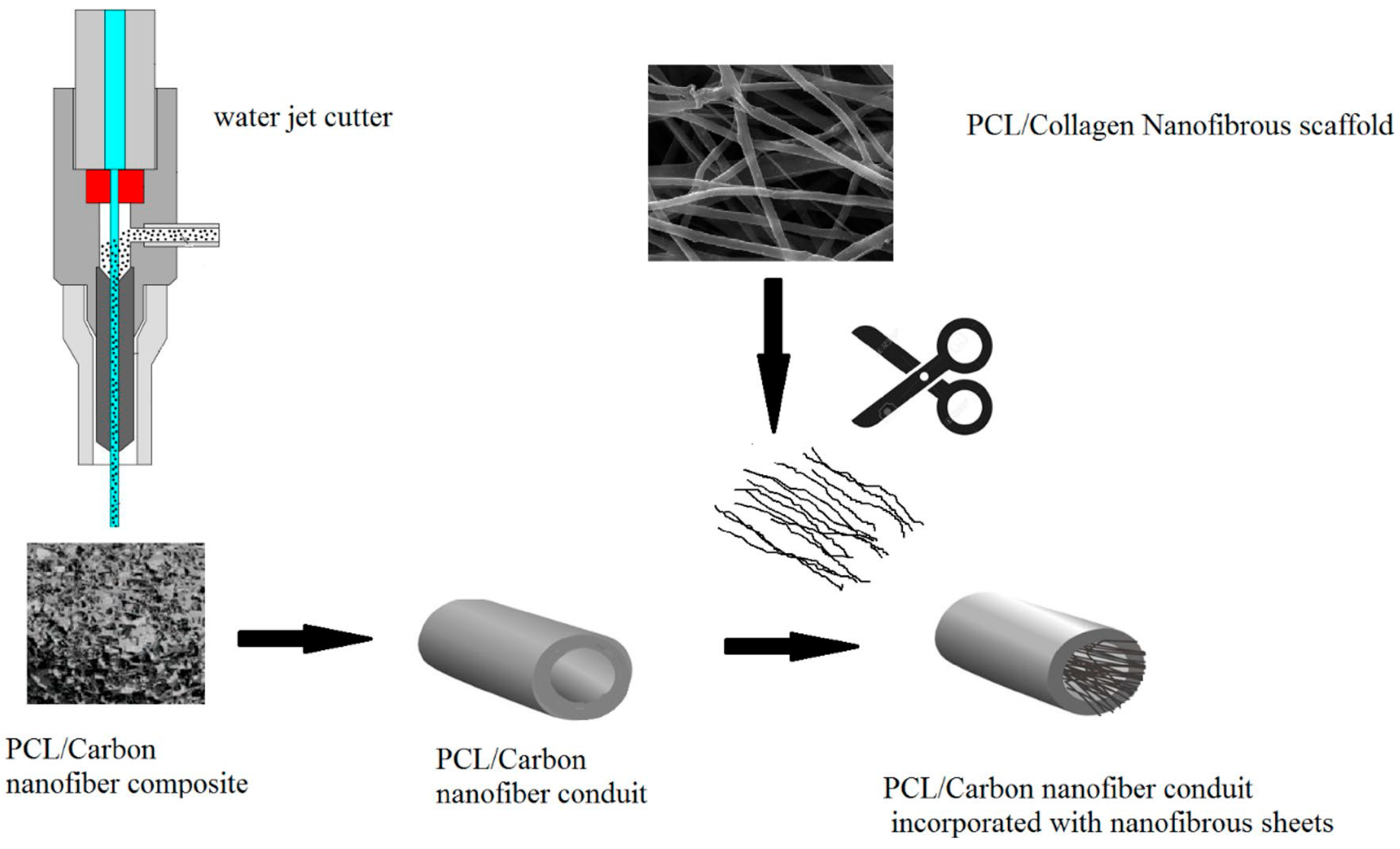
| PCL/Col | CNFs | Dioxane/acetic acid 7 | Microporous and nanofibrous 8 | TIPS + electrospinning | NEURAL TE | [59] |
| PLLA/CS | PDA/Qu 9 | Acetic acid | Microfibrous and nanofibrous 10 | TIPS + 3D printing | BONE TE | [63] |
| PLGA | nHA 11 | Dioxane | Microporous and macroporous 12 | TIPS + 3D printing | BONE TE | [22] |
| PLGA | EC | Microporous and knitted mesh 13 | TIPS + textile technology | DERMAL TE | [20] |
| Polymer System | Solvent System | Structure | Fabrication Technique | Porosity | Application | Reference |
|---|---|---|---|---|---|---|
| PLLA 1 | 1,4-dioxane | Anisotropic pores | TIPS | ~91–92% | Bone TE | [73] |
| polyurethane | DMSO | Anisotropic pores | TIPS (controlled heat direction) | ~93–97% | Cardiac patch | [71] |
| PLLGC | 1,4-dioxane | Oriented microtubular | TIPS | ~73–85% | TE | [25] |
| SF 2/Col | water/acetic acid 3 | radially/axially- aligned pores | TIPS (temperature gradient-guided) | ~85% | Osteochondral | [72] |
| PHBV 4 | 1,4-dioxane | Oriented pores, unidirectional channels | TIPS | ~41–77% | TE | [74] |
| PEUU | DMSO | Oriented connected macropores | TIPS | Rotator cuff repair | [66] | |
| PLLA | 1,4-dioxane 5 | Anisotropic pores, (~parallelepiped) | TIPS (solid-liquid phase separation) | ~75–95% | TE | [64] |
| PLGA | 1,4-dioxane | Radially-aligned pores | TIPS (uniaxial temperature gradient) | ~91% | Osteochondral | [62] |
Publisher’s Note: MDPI stays neutral with regard to jurisdictional claims in published maps and institutional affiliations. |
© 2021 by the authors. Licensee MDPI, Basel, Switzerland. This article is an open access article distributed under the terms and conditions of the Creative Commons Attribution (CC BY) license (http://creativecommons.org/licenses/by/4.0/).
Share and Cite
Zeinali, R.; del Valle, L.J.; Torras, J.; Puiggalí, J. Recent Progress on Biodegradable Tissue Engineering Scaffolds Prepared by Thermally-Induced Phase Separation (TIPS). Int. J. Mol. Sci. 2021, 22, 3504. https://0-doi-org.brum.beds.ac.uk/10.3390/ijms22073504
Zeinali R, del Valle LJ, Torras J, Puiggalí J. Recent Progress on Biodegradable Tissue Engineering Scaffolds Prepared by Thermally-Induced Phase Separation (TIPS). International Journal of Molecular Sciences. 2021; 22(7):3504. https://0-doi-org.brum.beds.ac.uk/10.3390/ijms22073504
Chicago/Turabian StyleZeinali, Reza, Luis J. del Valle, Joan Torras, and Jordi Puiggalí. 2021. "Recent Progress on Biodegradable Tissue Engineering Scaffolds Prepared by Thermally-Induced Phase Separation (TIPS)" International Journal of Molecular Sciences 22, no. 7: 3504. https://0-doi-org.brum.beds.ac.uk/10.3390/ijms22073504