
Visual Servoing Approach to Autonomous UAV Landing on a Moving Vehicle

 , , , and
Abstract
:1. Introduction
2. Background and Relevant Research
3. Materials and Methods
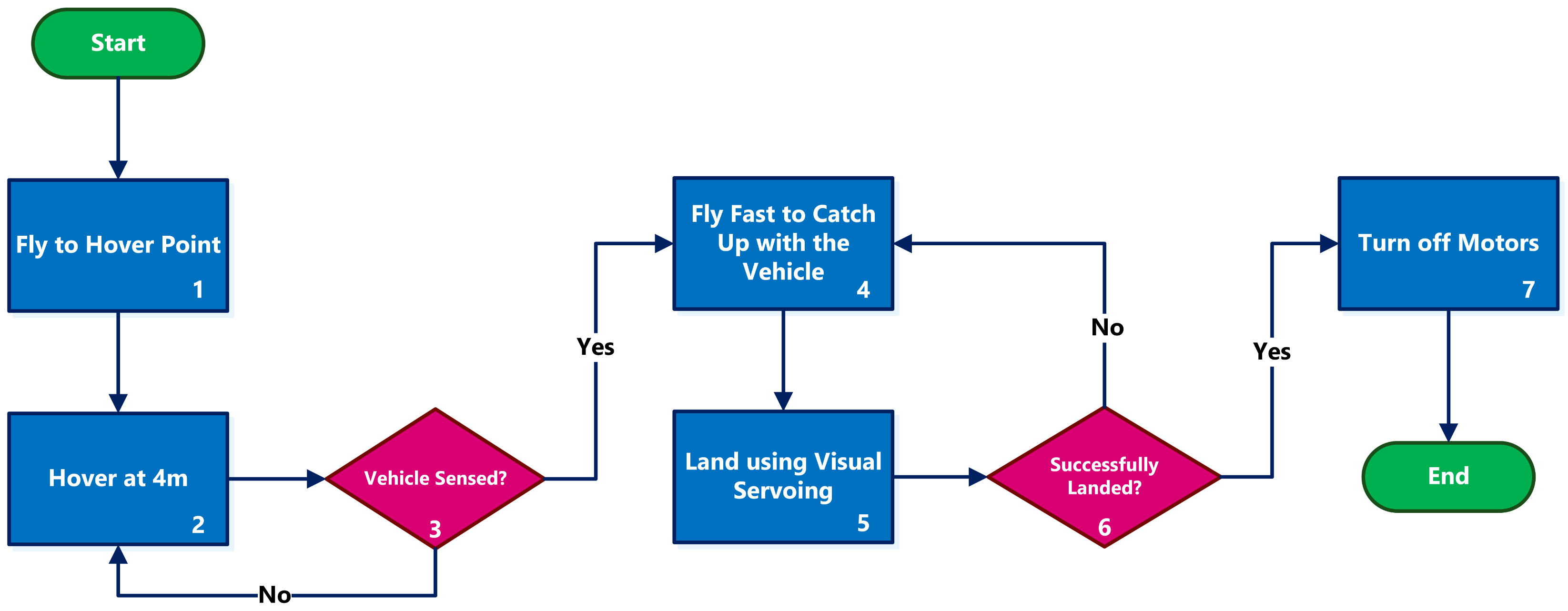
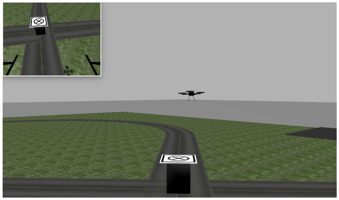
3.1. General Strategy
- The quadrotor hovers at the point at the height of h meters until it senses the passing ground vehicle.
- As soon as the ground vehicle is sensed, the UAV starts flying in the direction of movement with a predefined speed slightly higher than the vehicle speed to compensate for the distance between the UAV and the vehicle. This gap results from the delays in processing the sensors and dynamics of the UAV in getting up to the vehicle speed.
- After the initial acceleration, the UAV flies with a feed-forwarding speed equal to the ground vehicle speed. Then, the visual servoing controller tries to decrease the remaining gap between the UAV and the target.
- After successfully landing, magnets at the bottom of the UAV legs stick to the metal platform, and the propellers are shut down.
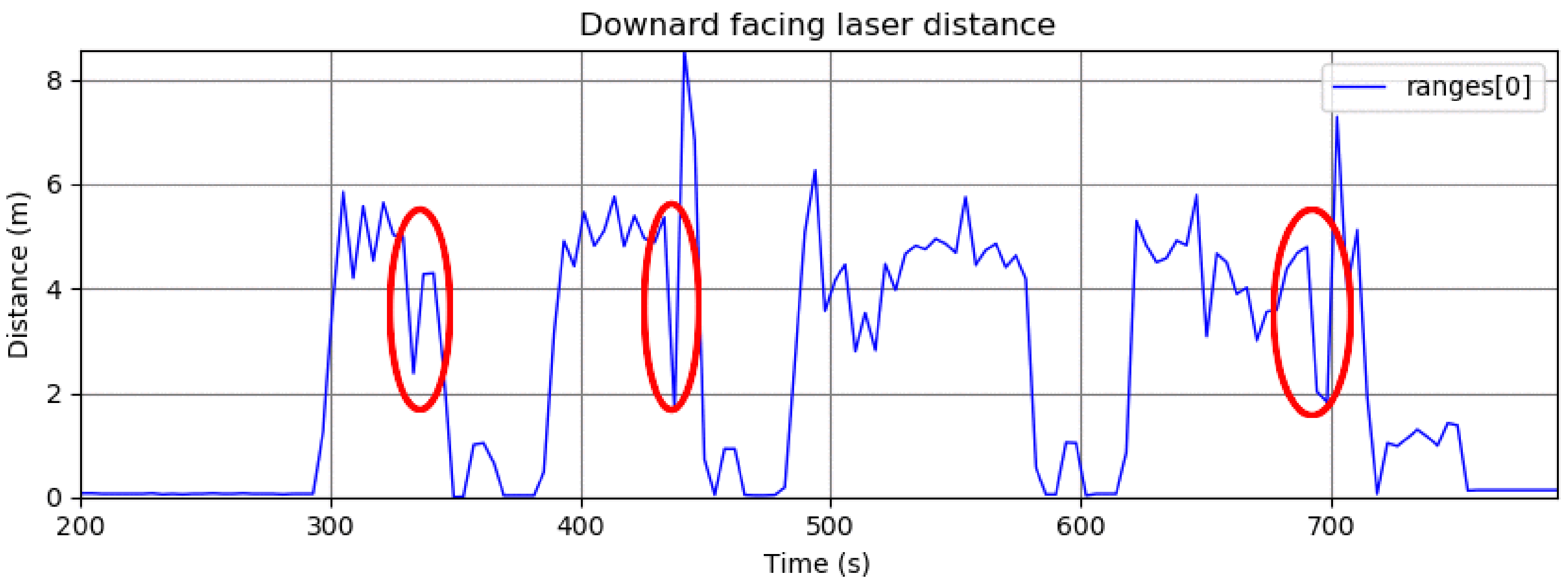
3.2. Sensing the Passing Vehicle
| Algorithm 1: Approach for sensing the passing vehicle using three point lasers. |
|
3.3. Landing Using Visual Servoing
3.3.1. Interaction Matrix
3.3.2. Calculating Quadrotor’s Velocity
3.4. Initial Quadrotor Acceleration
3.5. Final Steps and Landing
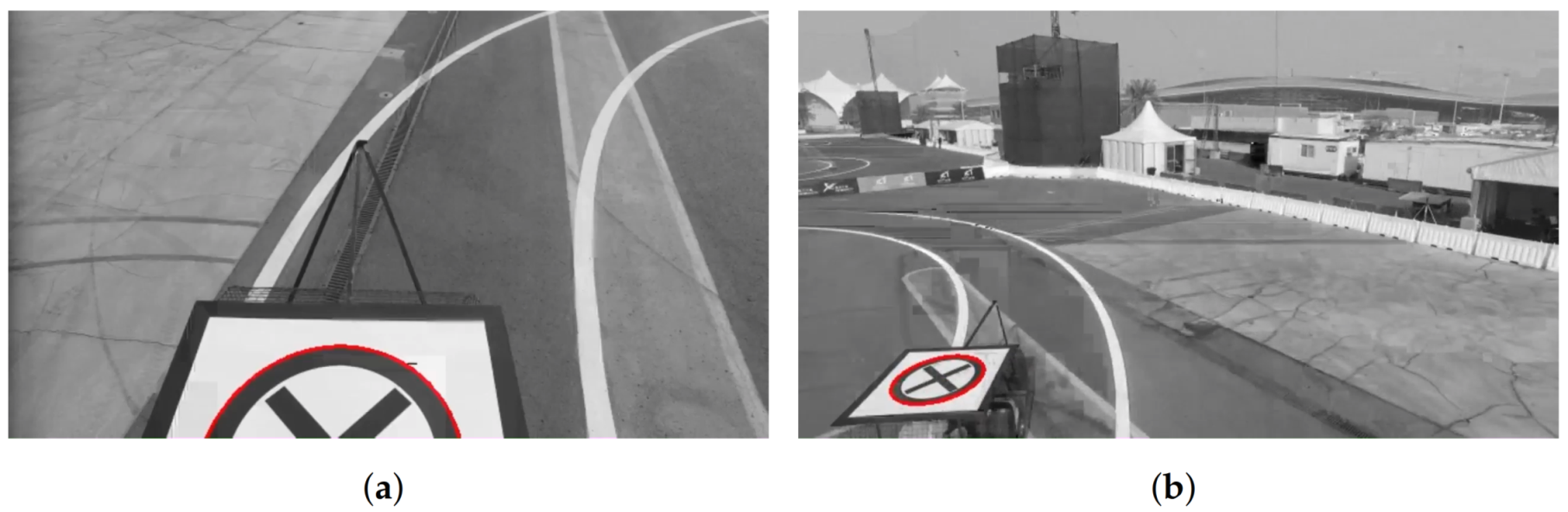
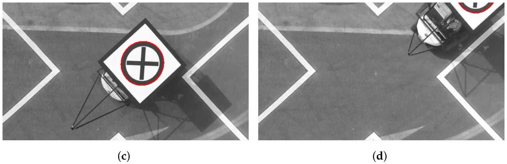
3.6. Detection and Tracking of the Deck
- This algorithm is used for landing the quadrotor on a moving vehicle. Therefore, it should work online (with a frequency greater than 10 Hz) on a resource-limited onboard computer.
- The shape details cannot be seen in the video frames when the quadrotor is flying far from the deck.
- The shape of the target is transformed by a projective distortion, which occurs when the shape is seen from different points of view.
- There is a wide range of illumination conditions (e.g., cloudy, sunny, morning, evening).
- Due to the reflection of the light (e.g., from sources like the sun or bulbs), the target may not always be seen in all the frames, even when the camera is close to the vehicle.
- In some frames, there may be shadows on the target shape (e.g., the shadow of the quadrotor or trees).
- In some frames, only a part of the target shape may be seen.
4. Experiments and Results
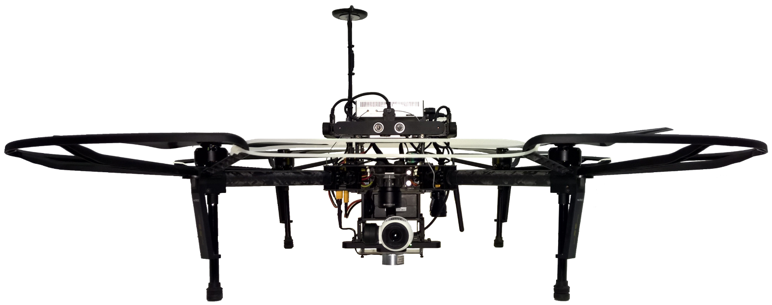
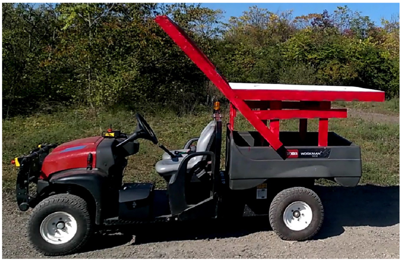
4.1. Hardware
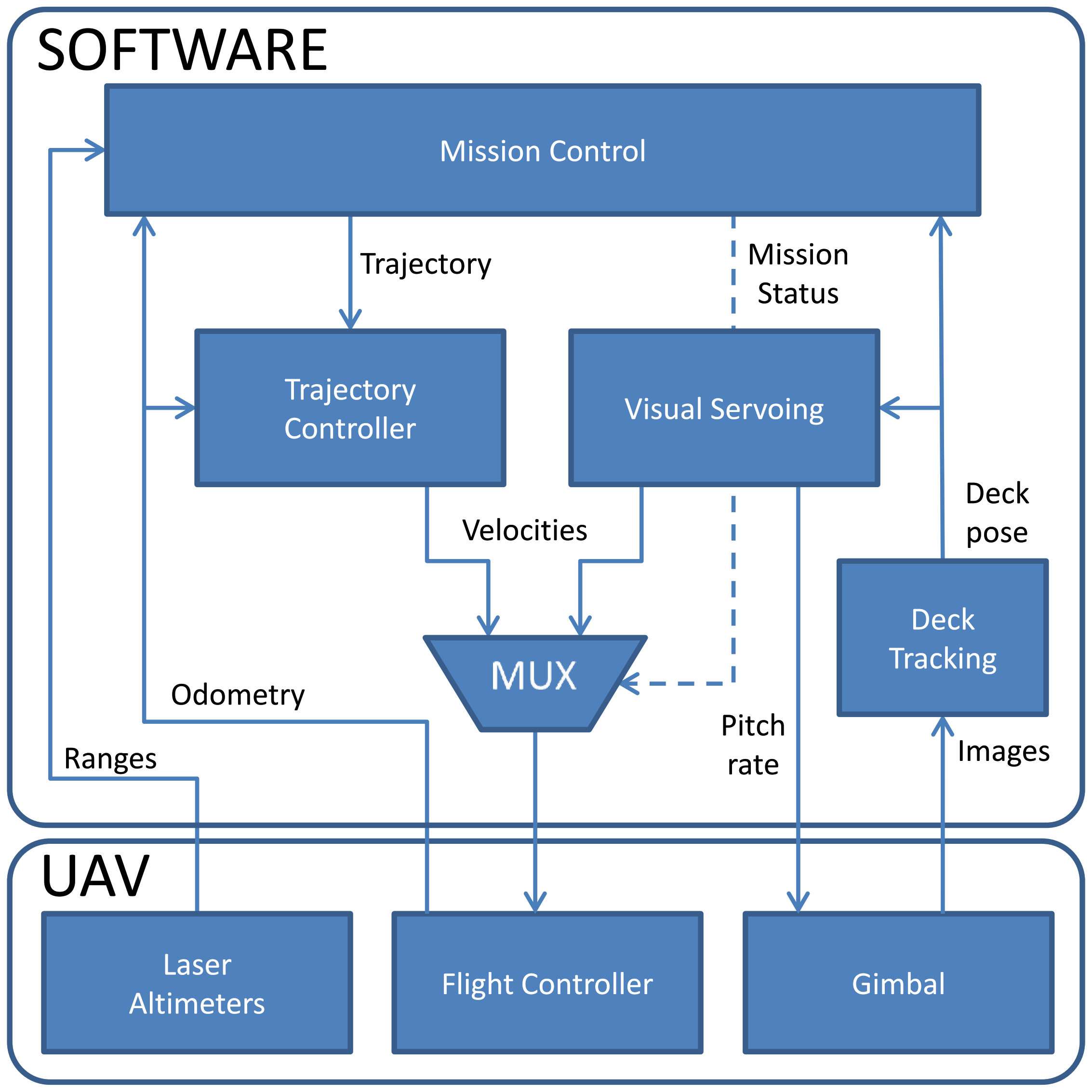
4.2. Software
- Deck tracking—detects the deck target and provides its position and orientation in the image reference frame;
- Visual Servoing—controls the UAV to track and approach the deck;
- Trajectory controller—provides velocity commands to the robot so it can follow the trajectories generated by the Mission Control node;
- Mux—selects the velocities to be sent to the quadrotor, depending on the mission status.
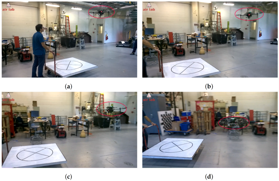
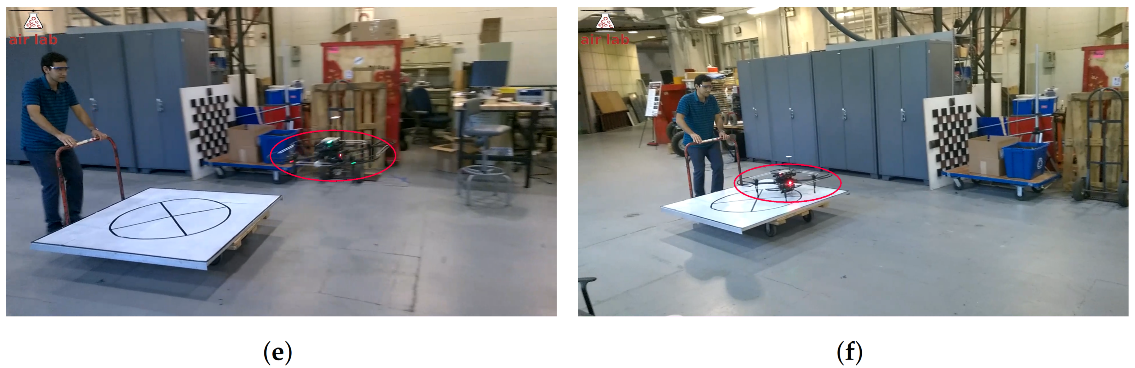
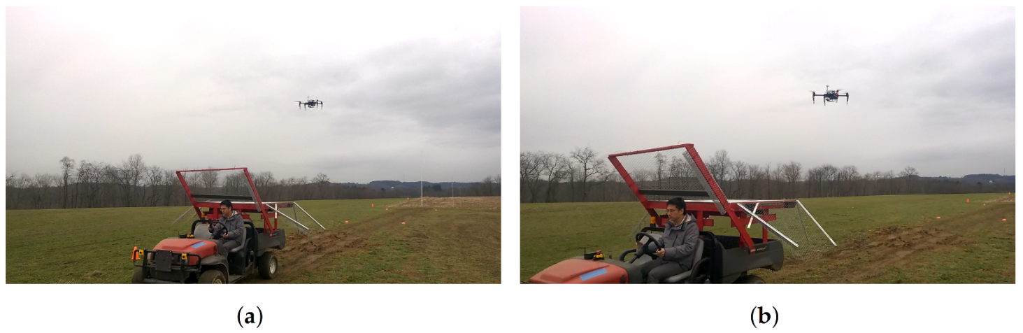
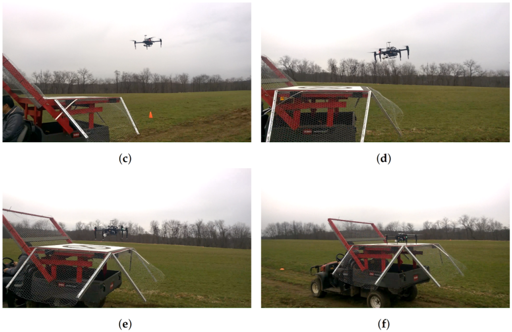
4.3. Test Results
5. Conclusions
Author Contributions
Funding
Institutional Review Board Statement
Informed Consent Statement
Data Availability Statement
Acknowledgments
Conflicts of Interest
Abbreviations
| UAV | Unmanned Aerial Vehicle |
| GPS | Global Positioning System |
| IMU | Inertial Measurement Unit |
| MBZIRC | Mohamed Bin Zayed International Robotics Challenge |
| RTK | Real-Time kinematic positioning |
| MPC | Model Predictive Control |
| RANSAC | Random Sample Consensus |
| RGB-D | Red, Green, Blue and Depth |
| MUX | Multiplexer |
References
- Bonatti, R.; Ho, C.; Wang, W.; Choudhury, S.; Scherer, S. Towards a Robust Aerial Cinematography Platform: Localizing and Tracking Moving Targets in Unstructured Environments. In Proceedings of the 2019 IEEE/RSJ International Conference on Intelligent Robots and Systems (IROS), Macau, China, 3–8 November 2019; pp. 229–236. [Google Scholar] [CrossRef]
- Keipour, A.; Mousaei, M.; Ashley, A.T.; Scherer, S. Integration of Fully-Actuated Multirotors into Real-World Applications. arXiv 2020, arXiv:2011.06666. [Google Scholar]
- Keipour, A. Physical Interaction and Manipulation of the Environment Using Aerial Robots. Ph.D. Thesis, Carnegie Mellon University, Pittsburgh, PA, USA, 2022. [Google Scholar]
- Arora, S.; Jain, S.; Scherer, S.; Nuske, S.; Chamberlain, L.; Singh, S. Infrastructure-free shipdeck tracking for autonomous landing. In Proceedings of the 2013 IEEE International Conference on Robotics and Automation, Karlsruhe, Germany, 6–10 May 2013; pp. 323–330. [Google Scholar] [CrossRef]
- Almeshal, A.; Alenezi, M. A Vision-Based Neural Network Controller for the Autonomous Landing of a Quadrotor on Moving Targets. Robotics 2018, 7, 71. [Google Scholar] [CrossRef]
- Saripalli, S.; Sukhatme, G.S. Landing on a Moving Target Using an Autonomous Helicopter. In Field and Service Robotics: Recent Advances in Research and Applications; Springer: Berlin/Heidelberg, Germany, 2006; pp. 277–286. [Google Scholar] [CrossRef]
- Wenzel, K.E.; Masselli, A.; Zell, A. Automatic Take Off, Tracking and Landing of a Miniature UAV on a Moving Carrier Vehicle. J. Intell. Robot. Syst. 2011, 61, 221–238. [Google Scholar] [CrossRef]
- Gautam, A.; Sujit, P.B.; Saripalli, S. A survey of autonomous landing techniques for UAVs. In Proceedings of the 2014 International Conference on Unmanned Aircraft Systems (ICUAS), Orlando, FL, USA, 27–30 May 2014; pp. 1210–1218. [Google Scholar] [CrossRef]
- Kim, J.; Jung, Y.; Lee, D.; Shim, D.H. Outdoor autonomous landing on a moving platform for quadrotors using an omnidirectional camera. In Proceedings of the 2014 International Conference on Unmanned Aircraft Systems (ICUAS), Orlando, FL, USA, 27–30 May 2014; IEEE: Piscataway, NJ, USA, 2014; pp. 1243–1252. [Google Scholar] [CrossRef]
- Bahnemann, R.; Pantic, M.; Popović, M.; Schindler, D.; Tranzatto, M.; Kamel, M.; Grimm, M.; Widauer, J.; Siegwart, R.; Nieto, J. The ETH-MAV Team in the MBZ International Robotics Challenge. J. Field Robot. 2019, 36, 78–103. [Google Scholar] [CrossRef]
- Beul, M.; Nieuwenhuisen, M.; Quenzel, J.; Rosu, R.A.; Horn, J.; Pavlichenko, D.; Houben, S.; Behnke, S. Team NimbRo at MBZIRC 2017: Fast landing on a moving target and treasure hunting with a team of micro aerial vehicles. J. Field Robot. 2019, 36, 204–229. [Google Scholar] [CrossRef]
- Alarcón, F.; García, M.; Maza, I.; Viguria, A.; Ollero, A. A Precise and GNSS-Free Landing System on Moving Platforms for Rotary-Wing UAVs. Sensors 2019, 19, 886. [Google Scholar] [CrossRef] [Green Version]
- Bhattacharya, A.; Gandhi, A.; Merkle, L.; Tiwari, R.; Warrior, K.; Winata, S.; Saba, A.; Zhang, K.; Kroemer, O.; Scherer, S. Mission-level Robustness with Rapidly-deployed, Autonomous Aerial Vehicles by Carnegie Mellon Team Tartan at MBZIRC 2020. Field Robot. 2022, 2, 172–200. [Google Scholar] [CrossRef]
- MBZIRC. MBZIRC Challenge Description, 2nd ed.; Khalifa University: Abu Dhabi, United Arab Emirates, 2015; Available online: www.mbzirc.com (accessed on 24 August 2022).
- Saripalli, S.; Sukhatme, G.S.; Montgomery, J.F. An Experimental Study of the Autonomous Helicopter Landing Problem. In Experimental Robotics VIII; Springer: Berlin/Heidelberg, Germany, 2003; pp. 466–475. [Google Scholar] [CrossRef]
- Borowczyk, A.; Nguyen, D.T.; Phu-Van Nguyen, A.; Nguyen, D.Q.; Saussié, D.; Le Ny, J. Autonomous Landing of a Quadcopter on a High-Speed Ground Vehicle. J. Guid. Control Dyn. 2017, 40, 1–8. [Google Scholar] [CrossRef]
- Lee, D.; Ryan, T.; Kim, H.J. Autonomous landing of a VTOL UAV on a moving platform using image-based visual servoing. In Proceedings of the 2012 IEEE International Conference on Robotics and Automation, Saint Paul, MN, USA, 14–18 May 2012; pp. 971–976. [Google Scholar] [CrossRef]
- Gonçalves, V.M.; McLaughlin, R.; Pereira, G.A.S. Precise Landing of Autonomous Aerial Vehicles Using Vector Fields. IEEE Robot. Autom. Lett. 2020, 5, 4337–4344. [Google Scholar] [CrossRef]
- Lange, S.; Sunderhauf, N.; Protzel, P. A vision based onboard approach for landing and position control of an autonomous multirotor UAV in GPS-denied environments. In Proceedings of the 2009 International Conference on Advanced Robotics, Munich, Germany, 22–26 June 2009; pp. 1–6. [Google Scholar]
- Merz, T.; Duranti, S.; Conte, G. Autonomous Landing of an Unmanned Helicopter based on Vision and Inertial Sensing. In Experimental Robotics IX: The 9th International Symposium on Experimental Robotics; Springer: Berlin/Heidelberg, Germany, 2006; pp. 343–352. [Google Scholar] [CrossRef]
- Xing, B.Y.; Pan, F.; Feng, X.X.; Li, W.X.; Gao, Q. Autonomous Landing of a Micro Aerial Vehicle on a Moving Platform Using a Composite Landmark. Int. J. Aerosp. Eng. 2019, 2019, 4723869. [Google Scholar] [CrossRef]
- Xuan-Mung, N.; Hong, S.K.; Nguyen, N.P.; Ha, L.N.N.T.; Le, T.L. Autonomous Quadcopter Precision Landing Onto a Heaving Platform: New Method and Experiment. IEEE Access 2020, 8, 167192–167202. [Google Scholar] [CrossRef]
- Wynn, J.S.; McLain, T.W. Visual Servoing for Multirotor Precision Landing in Daylight and After-Dark Conditions. In Proceedings of the 2019 International Conference on Unmanned Aircraft Systems (ICUAS), Atlanta, GA, USA, 11–14 June 2019; pp. 1242–1248. [Google Scholar]
- Romero-Ramirez, F.; Muñoz-Salinas, R.; Medina-Carnicer, R. Speeded Up Detection of Squared Fiducial Markers. Image Vis. Comput. 2018, 76, 38–47. [Google Scholar] [CrossRef]
- Ruffier, F.; Franceschini, N. Optic Flow Regulation in Unsteady Environments: A Tethered MAV Achieves Terrain Following and Targeted Landing Over a Moving Platform. J. Intell. Robot. Syst. 2015, 79, 275–293. [Google Scholar] [CrossRef] [Green Version]
- Herissé, B.; Hamel, T.; Mahony, R.; Russotto, F.X. Landing a VTOL Unmanned Aerial Vehicle on a Moving Platform Using Optical Flow. IEEE Trans. Robot. 2012, 28, 77–89. [Google Scholar] [CrossRef]
- Chang, C.W.; Lo, L.Y.; Cheung, H.C.; Feng, Y.; Yang, A.S.; Wen, C.Y.; Zhou, W. Proactive Guidance for Accurate UAV Landing on a Dynamic Platform: A Visual-Inertial Approach. Sensors 2022, 22, 404. [Google Scholar] [CrossRef] [PubMed]
- Cantelli, L.; Guastella, D.; Melita, C.D.; Muscato, G.; Battiato, S.; D’Urso, F.; Farinella, G.M.; Ortis, A.; Santoro, C. Autonomous Landing of a UAV on a Moving Vehicle for the MBZIRC. In Human-Centric Robotics, Proceedings of the CLAWAR 2017: 20th International Conference on Climbing and Walking Robots and the Support Technologies for Mobile Machines, Porto, Portugal, 11–13 September 2017; World Scientific: Singapore, 2017; pp. 197–204. [Google Scholar] [CrossRef]
- Battiato, S.; Cantelli, L.; D’Urso, F.; Farinella, G.M.; Guarnera, L.; Guastella, D.; Melita, C.D.; Muscato, G.; Ortis, A.; Ragusa, F.; et al. A System for Autonomous Landing of a UAV on a Moving Vehicle. In Image Analysis and Processing, Proceedings of the International Conference on Image Analysis and Processing, Catania, Italy, 11–15 September 2017; Battiato, S., Gallo, G., Schettini, R., Stanco, F., Eds.; Springer International Publishing: Cham, Switzerland, 2017; pp. 129–139. [Google Scholar]
- Baca, T.; Stepan, P.; Spurny, V.; Hert, D.; Penicka, R.; Saska, M.; Thomas, J.; Loianno, G.; Kumar, V. Autonomous landing on a moving vehicle with an unmanned aerial vehicle. J. Field Robot. 2019, 36, 874–891. [Google Scholar] [CrossRef]
- Tzoumanikas, D.; Li, W.; Grimm, M.; Zhang, K.; Kovac, M.; Leutenegger, S. Fully autonomous micro air vehicle flight and landing on a moving target using visual–inertial estimation and model-predictive control. J. Field Robot. 2019, 36, 49–77. [Google Scholar] [CrossRef]
- Falanga, D.; Zanchettin, A.; Simovic, A.; Delmerico, J.; Scaramuzza, D. Vision-based autonomous quadrotor landing on a moving platform. In Proceedings of the 2017 IEEE International Symposium on Safety, Security and Rescue Robotics (SSRR), Shanghai, China, 11–13 October 2017; IEEE: Piscataway, NJ, USA, 2017; pp. 200–207. [Google Scholar] [CrossRef]
- Keipour, A.; Pereira, G.A.; Scherer, S. Real-Time Ellipse Detection for Robotics Applications. IEEE Robot. Autom. Lett. 2021, 6, 7009–7016. [Google Scholar] [CrossRef]
- Hoffmann, G.M.; Waslander, S.L.; Tomlin, C.J. Quadrotor helicopter trajectory tracking control. In Proceedings of the AIAA Guidance, Navigation and Control Conference and Exhibit, Honolulu, HI, USA, 18–21 August 2008; pp. 1–14. [Google Scholar]
- Espiau, B.; Chaumette, F.; Rives, P. A new approach to visual servoing in robotics. IEEE Trans. Robot. Autom. 1992, 8, 313–326. [Google Scholar] [CrossRef]
- Hutchinson, S.; Hager, G.D.; Corke, P.I. A tutorial on visual servo control. IEEE Trans. Robot. Autom. 1996, 12, 651–670. [Google Scholar] [CrossRef]
- Marchand, É.; Spindler, F.; Chaumette, F. ViSP for visual servoing: A generic software platform with a wide class of robot control skills. IEEE Robot. Autom. Mag. 2005, 12, 40–52. [Google Scholar] [CrossRef] [Green Version]
- Corke, P.I.; Good, M.C. Dynamic effects in visual closed-loop systems. IEEE Trans. Robot. Autom. 1996, 12, 671–683. [Google Scholar] [CrossRef]
- Jin, R.; Owais, H.M.; Lin, D.; Song, T.; Yuan, Y. Ellipse proposal and convolutional neural network discriminant for autonomous landing marker detection. J. Field Robot. 2019, 36, 6–16. [Google Scholar] [CrossRef]
- Li, Z.; Meng, C.; Zhou, F.; Ding, X.; Wang, X.; Zhang, H.; Guo, P.; Meng, X. Fast vision-based autonomous detection of moving cooperative target for unmanned aerial vehicle landing. J. Field Robot. 2019, 36, 34–48. [Google Scholar] [CrossRef]
- Fornaciari, M.; Prati, A.; Cucchiara, R. A fast and effective ellipse detector for embedded vision applications. Pattern Recognit. 2014, 47, 3693–3708. [Google Scholar] [CrossRef]
- Koenig, N.; Howard, A. Design and use paradigms for Gazebo, an open-source multi-robot simulator. In Proceedings of the IEEE/RSJ International Conference on Intelligent Robots and Systems (IROS), Sendai, Japan, 28 September–2 October 2004; Volume 3, pp. 2149–2154. [Google Scholar]
- Meyer, J.; Sendobry, A.; Kohlbrecher, S.; Klingauf, U.; von Stryk, O. Comprehensive Simulation of Quadrotor UAVs Using ROS and Gazebo. In Simulation, Modeling, and Programming for Autonomous Robots, Proceedings of the Third International Conference, SIMPAR 2012, Tsukuba, Japan, 5–8 November 2012; Noda, I., Ando, N., Brugali, D., Kuffner, J.J., Eds.; Springer: Berlin/Heidelberg, Germany, 2012; pp. 400–411. [Google Scholar]


| Parameter | Value |
|---|---|
| Maximum time of flight | 19 min |
| Maximum horizontal speed | 17 m/s (61 km/h) |
| Maximum vertical speed | 4 m/s ( km/h) |
| External diameter (with propeller guards) | m |
| Height | m |
| Processor | Quad-core ARM CORTEX-A15 |
| RAM Memory | GB |
| Maximum robot speed | m/s (30 km/h) |
Publisher’s Note: MDPI stays neutral with regard to jurisdictional claims in published maps and institutional affiliations. |
© 2022 by the authors. Licensee MDPI, Basel, Switzerland. This article is an open access article distributed under the terms and conditions of the Creative Commons Attribution (CC BY) license (https://creativecommons.org/licenses/by/4.0/).
Share and Cite
Keipour, A.; Pereira, G.A.S.; Bonatti, R.; Garg, R.; Rastogi, P.; Dubey, G.; Scherer, S. Visual Servoing Approach to Autonomous UAV Landing on a Moving Vehicle. Sensors 2022, 22, 6549. https://0-doi-org.brum.beds.ac.uk/10.3390/s22176549
Keipour A, Pereira GAS, Bonatti R, Garg R, Rastogi P, Dubey G, Scherer S. Visual Servoing Approach to Autonomous UAV Landing on a Moving Vehicle. Sensors. 2022; 22(17):6549. https://0-doi-org.brum.beds.ac.uk/10.3390/s22176549
Chicago/Turabian StyleKeipour, Azarakhsh, Guilherme A. S. Pereira, Rogerio Bonatti, Rohit Garg, Puru Rastogi, Geetesh Dubey, and Sebastian Scherer. 2022. "Visual Servoing Approach to Autonomous UAV Landing on a Moving Vehicle" Sensors 22, no. 17: 6549. https://0-doi-org.brum.beds.ac.uk/10.3390/s22176549