Article

A Disturbance Rejection Control Strategy of a Single Converter Hybrid Electrical System Integrating Battery Degradation

FEMTO-ST Institute, FCLAB, Université Bourgogne Franche-Comté, UTBM, CNRS, Rue Ernest Thierry Mieg, F-90000 Belfort, France
*
Author to whom correspondence should be addressed.
Submission received: 1 May 2020 / Revised: 21 May 2020 / Accepted: 25 May 2020 / Published: 1 June 2020

Abstract

:
In order to improve the durability and economy of a hybrid power system composed of a battery and supercapacitors, a control strategy that can reduce fluctuations of the battery current is regarded as a significant tool to deal with this issue. This paper puts forwards a disturbance rejection control strategy for a hybrid power system taking into account the degradation of the battery. First, the degradation estimation of the battery is done by the model-driven method based on the degradation model and Cubature Kalman Filter (CKF). Considering the transient and sinusoidal disturbance from the load in such a hybrid system, it is indispensable to smooth the behavior of the battery current in order to ensure the lifespan of the battery. Moreover, the constraints for the hybrid system should be considered for safety purposes. In order to deal with these demands, a cascaded voltage control loop based on a super twisting controller and proportional integral controller with an anti-windup scheme is designed for regulating the DC bus voltage in an inner voltage loop and supercapacitors’ voltage in an outer voltage loop, respectively. The specific feature of the proposed control method is that it operates like a low-pass filter so as to reduce the oscillations on the DC bus.

1. Introduction

The world is facing some serious environmental problems, such as the fossil energy crisis, global warming caused by greenhouse gas emissions, etc. [1,2,3]. Traditional vehicles account for a large proportion of carbon dioxide emissions [4]. Many countries and global organizations have tried to develop environmentally friendly vehicles to replace traditional fossil energy vehicles. Therefore, hybrid electric vehicles based on batteries as the main power source are regarded as the most promising technology to solve the energy crisis and reduce greenhouse gas emissions [5,6].
Due to their light weight, high energy density, and wide operating temperature range, lithium batteries are widely used in many fields, such as mobile phones, laptops, electric vehicles, household appliances, etc. [7,8]. When a battery is used in a electric vehicle, there are disadvantages such as slow response and short life [9]. The ratio of the peak power-to-the average power of an electric vehicle can reach 16:1. This often causes the battery to withstand large peak currents, which will accelerate the degradation of the battery [10,11]. The performance of the battery degrades greatly after many times of discharging/charging, which severely limits the use and promotion of electric vehicles [12,13,14]. The supercapacitor lifetime is more than one million cycles and possesses a higher power density (300–5000 W/kg) [15,16]. Therefore, supercapacitors are applied to electric vehicles to improve battery durability to provide and absorb peak power [17,18]. It is very important to set effective control strategies for the hybrid system that integrate the battery and supercapacitors to further improve system durability.
Usually, the structure of the hybrid system is divided into three categories: fully-active, passive, and semi-active [19,20]. For the fully-active structure, two DC/DC converters are used, which lead to more flexible control, but a higher cost. For the passive structure, no DC/DC converter is used, which results in less cost, but poor performance. For the semi-active structure, one DC/DC converter is adopted. Considering the economics and control effects, one DC/DC converter is used here.
For the control of hybrid systems, some researchers have proposed different control strategies. The work in [21] proposed the model predictive control for fuel cell/battery/supercapacitor hybrid power sources with the fully-active structure. The work in [22] proposed the passivity-based controller for a PV/battery/fuel cell/electrolyzer hybrid power system with the fully-active structure. The work in [23] proposed the fuzzy logic controller for the fuel cell and supercapacitor hybrid source with the fully-active structure. At present, there are few studies on the semi-active structure. In addition, none of the above control methods considered the degradation of the hybrid system. Some other researchers studied data-driven control, which is useful to design the proper controller for a complex system based on fitting the system models to the recorded experimental data [24,25,26]. The data-driven control focuses on the dynamic response of the system [27,28]. However, the constraints and degradation of internal devices are not easy to consider with data-driven control currently. Therefore, a disturbance rejection control strategy considering the constraints and degradation of internal devices is proposed in this paper.
As the hybrid system operates, both the battery and the supercapacitors will experience degradation in performance. The most common degradation phenomena of batteries are the loss of electrode active materials, the loss of lithium caused by side reactions, and the increase of resistance by solid electrolyte interface growth and current collector corrosion [29,30,31]. The degradation prognosis of the battery is usually made by the model-driven method and data-driven method [32,33]. The model-driven methods predict the degradation of the battery by the empirical or semi-empirical model [34]. The data-driven methods use artificial intelligence to predict the degradation of the battery based on many historical data [35]. The model-driven method considering the battery operation is more suitable for battery control modeling. In the long-term operation of the battery, the maximum available capacity, internal resistance, and power of the battery will change [36,37,38]. The supercapacitors have a much longer service life than the battery, so their degradation is negligible [39]. In this paper, the degradation of the battery is considered in the design of the control algorithm to improve the dynamic response of hybrid system effectively. Moreover, in this hybrid system, some transient and sinusoidal disturbances may occur from the load, which will lead to some oscillations on the DC bus and influence the behavior of the battery current. In order to deal with these uncertain disturbances, it is obligatory to design a robust control strategy. Due to the fact that the Super Twisting (ST) sliding mode controller is one of the best choices for controlling the perturbed system with uncertainty and unexpected fluctuations, ST is adopted in this paper [40,41,42,43,44,45,46,47].
This paper proposes a disturbance rejection control strategy for a single converter hybrid electrical system integrating battery degradation. The main contributions of this paper are as follows:
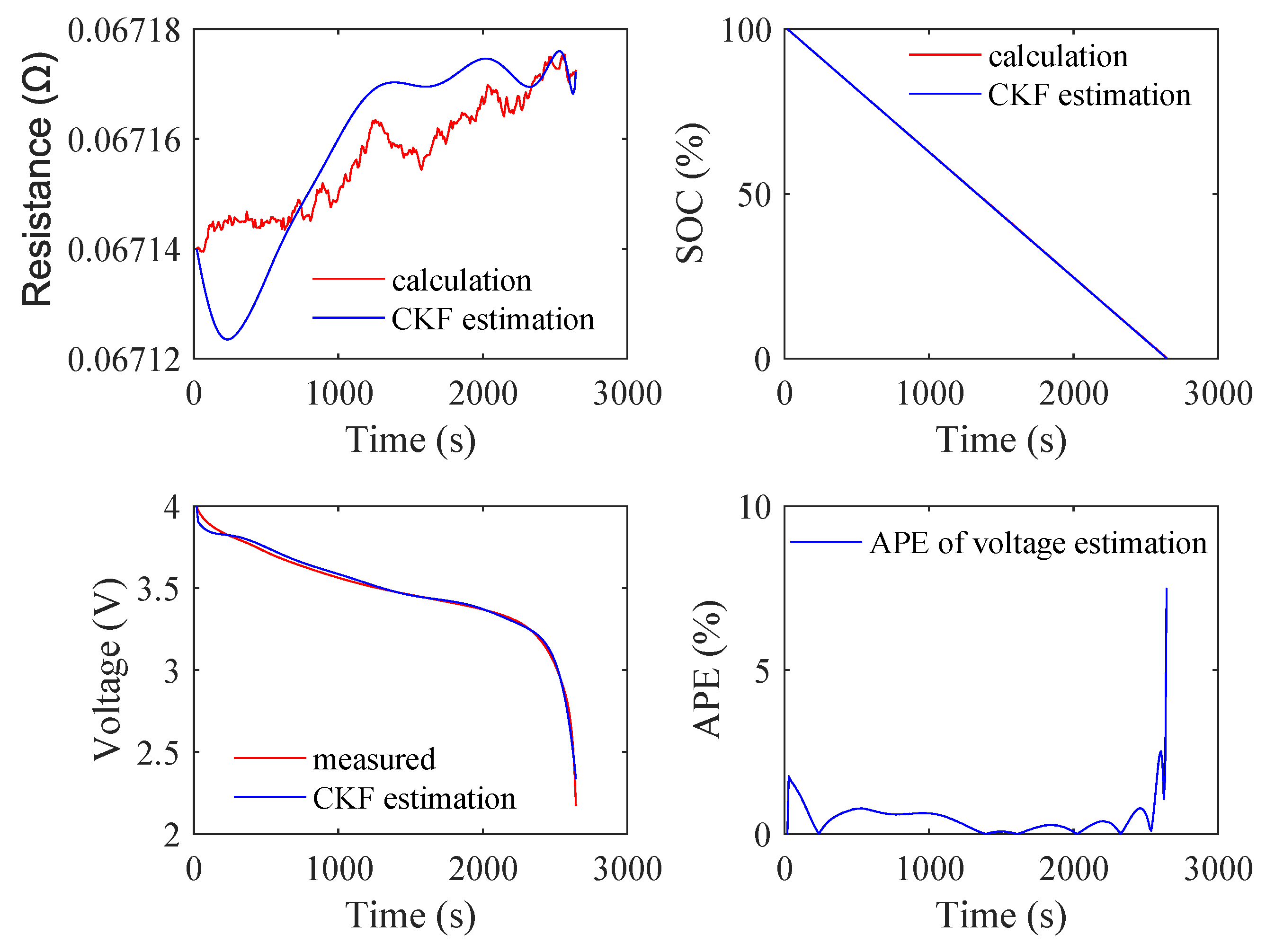
  • The degradation of the battery is estimated based on the battery degradation model and the Cubature Kalman Filter (CKF). The CKF can effectively provide battery aging status, and the estimated degradation state can be applied in the control design of the hybrid system.
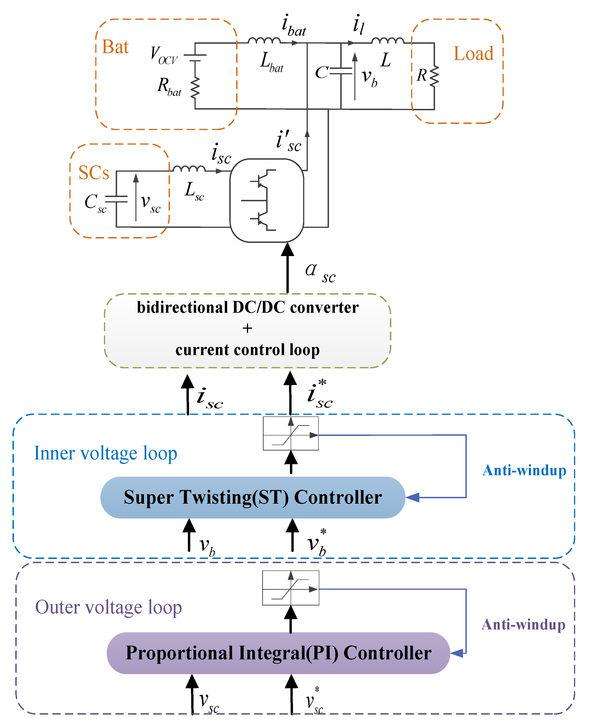
  • A cascaded voltage control loop is designed based on the Super Twisting (ST) controller and the Proportional Integral (PI) controller for the single converter hybrid electrical system considering the degradation of the battery. Moreover, the constraints of the battery and supercapacitors are integrated in the anti-windup schemes for protection purposes.
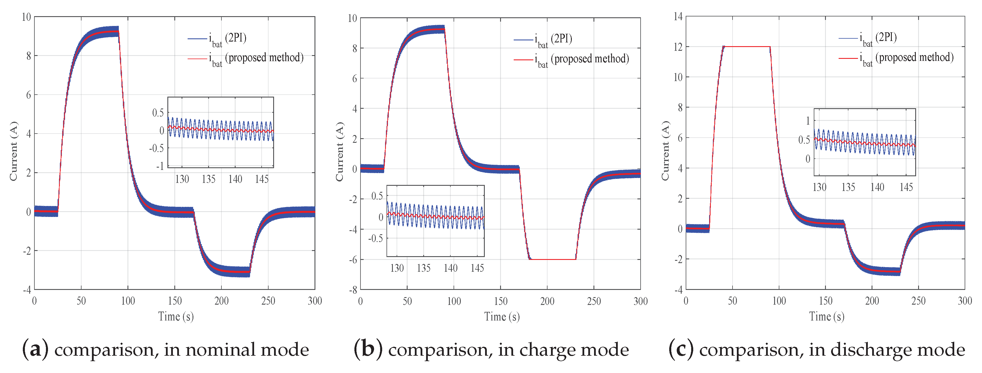
  • The effectiveness of the proposed control strategy is validated by simulations in three operation modes and different State Of Charge (SOC) conditions. Besides, the comparison simulation is done between the proposed control strategy and the method of two PI controllers. It shows that the proposed control strategy has good robustness and operates like a low-pass filter, which can be applied in rejecting the disturbance for the hybrid system in this paper.
This paper is organized as follows. In Section 2, the degradation of the battery is estimated by the battery degradation model and CKF. The control strategy based on the anti-windup ST controller and anti-windup PI controller and the current limitation constraints of the battery and supercapacitors are illustrated in Section 3. In Section 4, the simulation results and discussions are presented to verify the effectiveness of the proposed control strategy. The main conclusions are presented in Section 5.

2. Battery Degradation

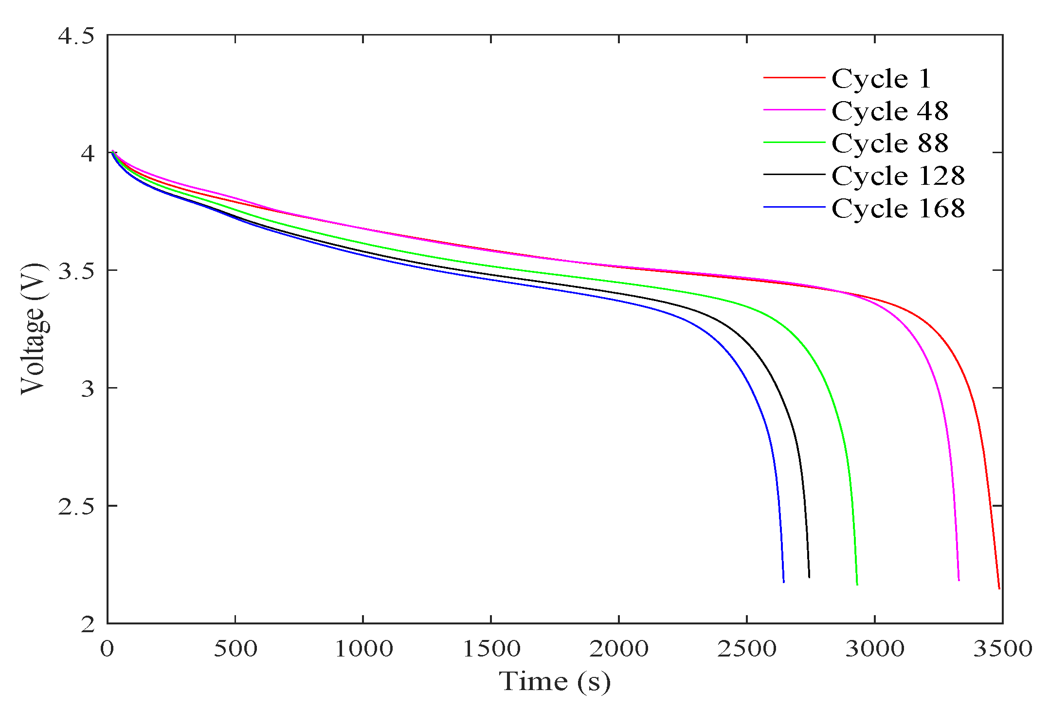
2.1. Battery Degradation Experiment

The Li-ion battery was operated through three different running modes (charge, discharge, and electrochemical impedance spectroscopy) at room temperature [48]. The battery was charged at a Constant Current (CC) of 1.5 A until the voltage reached 4.2 V and then at a constant voltage until the charging current dropped to 20 mA. The battery was discharged at a CC of 2 A until the voltage dropped to 2.2 V. The electrochemical impedance spectroscopy was performed at frequency sweep from 0.1 Hz to 5 kHz. The battery experienced 168 charge and discharge cycles, as shown in Figure A1 in Appendix A.
As shown in Figure A1, the operating time of the battery was significantly reduced as the discharge cycle increased. As the battery degraded, the battery capacity would decrease, and the battery internal resistance would increase. This would bring great challenges to the control system.

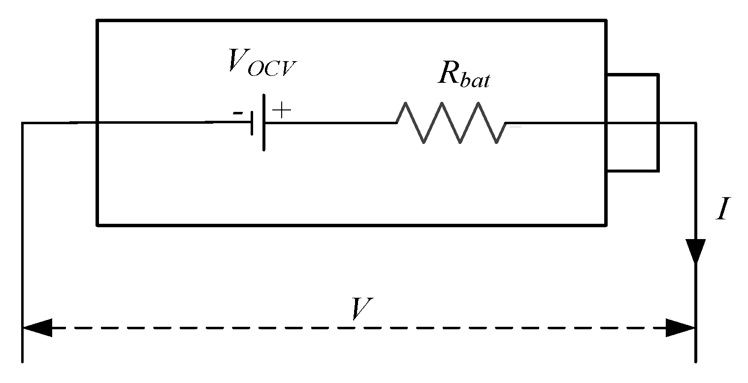
2.2. Battery Degradation Model

The battery degradation model consisted of an Open Circuit Voltage (OCV) and an internal resistance connected in series [49], as shown in Figure 1. The OCV is the measurement terminal voltage of the battery when the load current is zero. The OCV is a nonlinear function of the State Of Charge (SOC). The relationship between OCV and SOC is shown in Figure A2 in Appendix A. When the SOC of the battery is less than 20% or greater than 80%, the measurement terminal voltage drops faster.
The battery state equations are as follows:
S O C ( t + 1 ) = S O C ( t ) ( I ( t ) · Δ T ) / Q m a x + w 1
R b a t ( t + 1 ) = R b a t ( t ) + w 2
where I ( t ) is the battery current at time t, Q m a x is the lithium battery’s total capacity, and Δ T is the sampling period. w 1 and w 2 are process noises.
The voltage observation equation is as follows:
V ( t + 1 ) = V O C V [ S O C ( t ) ] I ( t ) · R b a t ( t ) + v
where V O C V [ S O C ] is the nine-order function for SOC and v is the observation noise.

2.3. Degradation Estimation Based on the Cubature Kalman Filter

The nonlinear system can be expressed by the following formula.
x k + 1 = f ( x k , u k ) + w k
y k + 1 = h ( x k + 1 , u k ) + v k
where x k + 1 = [ S O C ( t + 1 ) ; R b a t ( t + 1 ) ] T is the system state, y k + 1 = [ V ( t + 1 ) ] is the output state of the system, u k is the input of the system, f is the state transfer function from x k to x k + 1 , h represents the system measurement function, and w k and v k represent the system process noise and system measurement noise, respectively. w k and v k are considered as the Gaussian noises with zero mean and covariance Q and R.
CKF is based on a third-degree spherical-radial cubature rule and uses a set of cubature points to approximate the state mean and covariance of a nonlinear system with Gaussian noise [50,51,52]. The main calculation steps of CKF are shown in Appendix B.
The SOC and internal resistance are estimated by CKF and the degradation model. As shown in Figure 2, the estimated SOC and internal resistance were close to the calculations. The CKF estimated voltage was close to the measured terminal voltage. The maximum Absolute Percentage Error (APE) between the measurement terminal voltage and CKF estimated voltage was less than 8%. The mean APE between the measurement terminal voltage and CKF estimated voltage was about 0.49%. The estimated degradation state was applied to design the control systems.

3. Control Strategy for the Hybrid System

3.1. Control Structure of the Hybrid Power System

In this work, the hybrid power system was based on the battery and supercapacitors. The topology and control structure of the hybrid power system is illustrated in Figure 3. The battery was the main power source, and supercapacitors provided the transient power. The architecture of this hybrid system adopted the semi-active structure where only a single DC/DC converter was used.
As shown in Figure 3, the proposed control structure was on the basis of cascaded control loop where the inner voltage loop was mainly based on an ST controller, and the outer voltage loop was mainly based on a PI controller. In each voltage loop, an anti-windup scheme was designed in order to prevent the occurrence of integral saturation. The complete model of the hybrid power system can be represented as the following equations.
d d t v b ( t ) = i b a t ( t ) + ( 1 a s c ( t ) ) i s c ( t ) i l ( t ) C
d d t v s c ( t ) = i s c ( t ) C s c
d d t i s c ( t ) = v s c ( t ) v b ( t ) ( 1 a s c ( t ) ) L s c
i b a t ( t ) = V o c v v b ( t ) R b a t
where i b a t ( t ) is the battery current, i s c ( t ) is the supercapacitors’ current, i l ( t ) is the load current, v b ( t ) is the DC bus voltage, v s c ( t ) is the supercapacitors voltage, and a s c is the duty cycle of the bidirectional DC/DC converter.
As shown in Figure 3, the reference current of the supercapacitors i s c was regulated via the DC/DC converter with its own current control loop. In order to design the controller in the inner voltage loop, the bandwidth of the DC/DC converter was presumed as decoupled from the inner voltage loop. The following relationship could be deduced with this hypothesis.
L s c d d t i s c ( t ) = 0
Substituting (10) into the (8), the following equation can be obtained.
a s c ( t ) = 1 v s c ( t ) v b ( t )
Hence, the dynamic expression of the DC bus voltage can be represented as (12) and (13), where i s c ( t ) is the new input of this reduced system.
C d d t v b ( t ) = v s c ( t ) v b ( t ) i s c ( t ) + i b a t ( t ) i l ( t )
with:
i s c ( t ) = v s c ( t ) v b ( t ) i s c ( t )

3.2. Inner Voltage Loop

According to the cascaded loop in Figure 3, the inner voltage loop aimed to regulate the voltage of DC bus to its reference value so as to attenuate the external perturbations and transient changes from the load side. In this work, the controller of the inner voltage loop adopted the ST controller, which is a type of sliding mode controller and is notable for its robustness in the presence of uncertain conditions. The sliding mode surface s and control law u in this paper are defined as follows:
s = v b v b
u = v s c v b · i s c
Then, the derivative of sliding mode surface is presented as below.
s ˙ = v b ˙ v b ˙
Substituting (12) into the (16), the following equation can be obtained.
s ˙ = u + i b a t i l C v b
namely:
s ˙ = 1 C u + i b a t i l C v b
According to [53], the ST algorithm is defined as (19).
u = λ | s | 1 2 s i g n ( s ) α s i g n ( s ) d t
In (19), s is the sliding mode surface, which is defined as the difference value between the voltage of the DC bus v b and the reference voltage of the DC bus v b ; λ and α are the control gains; u is defined as i s c . s i g n ( s ) represents the symbolic function, which means that when the value of s is positive, negative, or zero, the value of s i g n ( s ) will be 1, −1, or 0, respectively. Therefore, (19) can be represented as follows:
i s c = λ | v b v b | 1 2 s i g n ( v b v b ) α s i g n ( v b v b ) d t
As shown in (19), the control law u consists of two parts. The former part λ | s | 1 2 s i g n ( s ) permits getting a soft response via ensuring the derivative of the sliding mode surface to zero. The latter part α s i g n ( s ) allows converging the sliding mode surface to zero. According to (18), the derivative of the sliding mode surface can be written in the following form.
s ˙ = ρ ( . ) u + ψ ( . )
where:
ρ ( . ) = 1 C
ψ ( . ) = i b a t i l C v b
According to [54], in order to ensure system stability, the gain parameters λ and α for the ST algorithm are chosen as follows.
α > C o k m
λ 2 4 C o k M ( β + C o ) k m 3 ( β C o )
where k m , k M , and C o depend on the system, | ψ ( . ) | < C o and k m < ρ ( . ) < k M . Then, the parameters are tuned to satisfy the dynamic requirement of the battery.
Moreover, in order to avoid the integral saturation and ensure the security of supercapacitors, the anti-windup scheme is added in the inner voltage loop.
For the mentioned ST algorithm, the stability mechanism can be verified by the Lyapunov function V n o m in [55,56]:
V n o m = α | s | + 1 2 υ 2
where | s | represents the voltage error and υ is defined as [ α s i g n ( s ) ] d t . In order to prove that the Lyapunov function converges to zero in finite time, V n o m must be semi-negative definite. According to (12), the mentioned dynamic system can be expressed as follows.
x ˙ = b u + G
where u is the control input and G represents the disturbance and the parameters uncertainties in System (12).
Suppose the boundary of disturbance G is as follows.
G G m a x | s | 1 2
Therefore, the differential form of V n o m can be presented as follows.
V ˙ n o m α s i g n ( s ) ( λ | s | 1 2 s i g n ( s ) + G m a x | s | 1 2 )
When choosing λ > G m a x , this differential form is negative definite, which means that the system has asymptotic stability.

3.3. Outer Voltage Loop

As shown in Figure 3, the outer voltage loop aims to regulate the voltage of the supercapacitors to its nominal condition via indirectly controlling the current of the battery and thereupon the voltage of the DC bus. Considering the infinitesimal relationship of (9) and assuming the inner voltage loop has faster dynamic compared with the outer voltage loop, the voltage of the DC bus is supposed to be equal to its reference voltage value. The controller of the outer voltage loop adopts the PI controller, which is designed as (30).
v b = k p ( v s c v s c ) + k i ( v s c v s c ) d t
In (30), k p represents the gain of the proportional term, and k i represents the gain of the integral term. Meanwhile, the anti-windup scheme is added in the outer voltage loop so as to avoid the integral saturation and protect the battery.

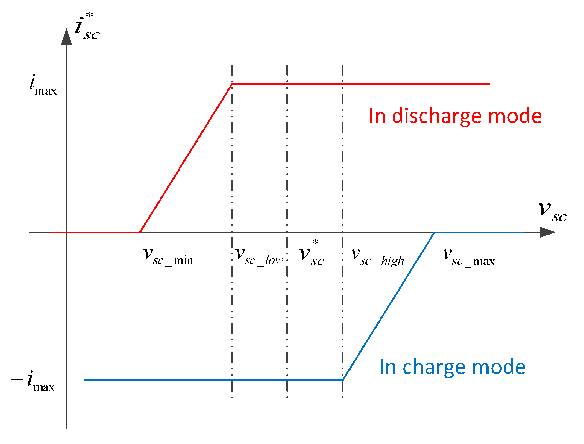
3.4. Constraints of the Hybrid Power System

In this hybrid power system, component constraints are considered to protect the operation of the supercapacitors and battery. The first constraint that is integrated in the anti-windup scheme of inner voltage loop aims to limit the current of the supercapacitors. The principle of this constraint is illustrated in Figure 4.
As shown in Figure 4, the safe voltage range of the supercapacitors is [ v s c _ m i n , v s c _ m a x ] . Within this range, the security thresholds of the supercapacitors reference voltage v s c are defined as v s c _ l o w and v s c _ h i g h . The blue curve and red curve represent the supercapacitors operating in charge mode and discharge mode, respectively. When the voltage of the supercapacitors reaches the maximum threshold or minimum threshold, the absolute value of the supercapacitors’ reference current will decrease quickly so as to ensure the supercapacitors are in a safe operation condition. The mathematical expressions of this constraint are concluded in (31) and (32).
i s c _ m a x _ c h a = i m a x · m a x 1 , m i n 0 , v s c v s c _ m a x v s c _ m a x v s c _ h i g h
i s c _ m a x _ d i s = i m a x · m i n 1 , m a x 0 , v s c v s c _ m i n v s c _ l o w v s c _ m i n
The second constraint that is integrated in the anti-windup scheme of the outer voltage loop aims to limit the current of the battery. According to Fig.3, the battery is linked to the load directly. Due to this reason, the current of the battery is indirectly regulated via controlling the voltage of the DC bus. The fixed voltage range of the DC bus is [ v b _ m i n , v b _ m a x ] . Within this range, after calculating by the outer voltage loop, the dynamic thresholds of the DC bus reference voltage v b are defined as v b _ m i n _ d y n and v b _ m a x _ d y n . The expressions of the second constraint are summarized in (33) and (34).
v b _ m a x _ d y n = v b + K i b a t ( i b a t ( t ) i b a t _ m a x _ c h a )
v b _ m i n _ d y n = v b + K i b a t ( i b a t ( t ) i b a t _ m a x _ d i s )
Overall, there are two main advantages of the proposed method. The first advantage is that the proposed method presents a new controller to attenuate the oscillations on the DC bus. The proposed super twisting controller adopted in the inner voltage loop operates like a low-pass filter so as to reject the perturbations from the load to the DC bus. The second advantage is that the proposed method takes into account the practical situation, such as the limitation of battery current and supercapacitors’ current. These practical constraints are considered and integrated in the anti-windup schemes of the inner voltage loop and outer voltage loop. Therefore, the proposed method has application value in a practical hybrid battery/supercapacitor system. Besides, there is a disadvantage of the proposed method as well. The gains of the super twisting controller are constant, so that the proposed method may be overestimated in the practical case due to these fixed parameters.

4. Simulation Results and Analysis

In order to verify the effectiveness of the proposed control strategy for the hybrid power system considering battery degradation, the simulation study was carried out with MATLAB. As shown in the Figure 3 in Section 3, the semi-active architecture and its associated control structure based on a cascaded control loop were taken into account in this simulation study. According to (19) and (30), which present the control theory of the super twisting controller and PI controller, the gains of these two controllers were considered in the simulation. Besides, the limitation theory for the supercapacitors and battery current was implemented in the anti-windup scheme in this simulation study based on the constraints shown in (31)–(34). The dynamic thresholds in the anti-windup scheme would be activated when these two power sources reach their limitation in the simulation. Moreover, the hybrid system in this simulation considered the battery degradation theory based on degradation model and CKF in Section 2 as well. With the theory of CKF according to Appendix B, the SOC and internal resistance of battery were estimated and utilized in this simulation. In this simulation, the disturbance of the load current was assumed as a sinusoidal perturbation current with a frequency of 7.5 Hz and an amplitude of 2 A. For supercapacitors, the initial reference voltage was 125 V, the voltage range [62.5 V, 136 V], and the low voltage security threshold and high voltage security threshold 93.75 V and 131 V, respectively. For the DC bus, the maximum threshold and minimum threshold were 55.5 V and 30 V, respectively. The initial desired voltage of the battery was achieved by connecting 12 battery cells studied in Section 2 in series.

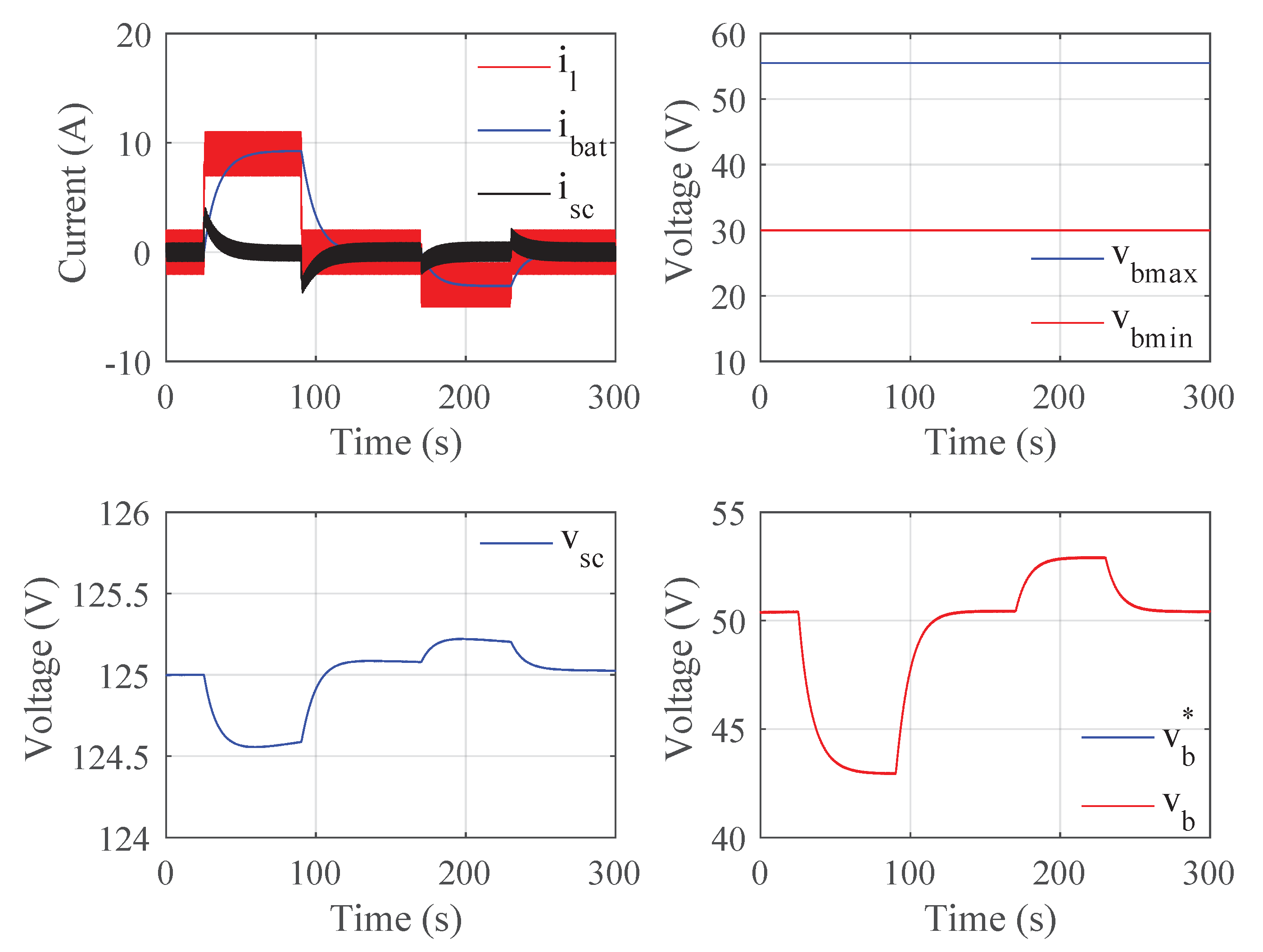
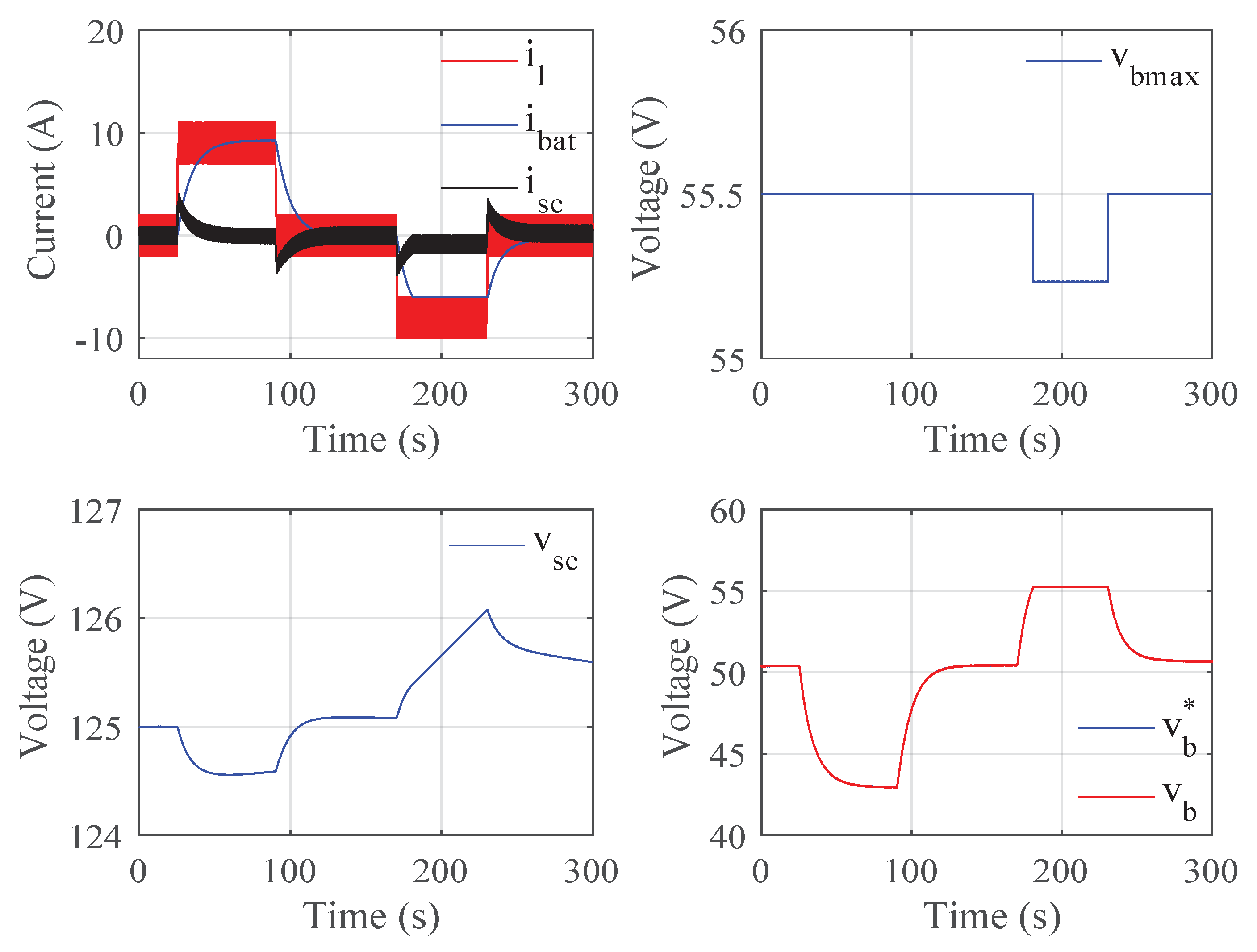
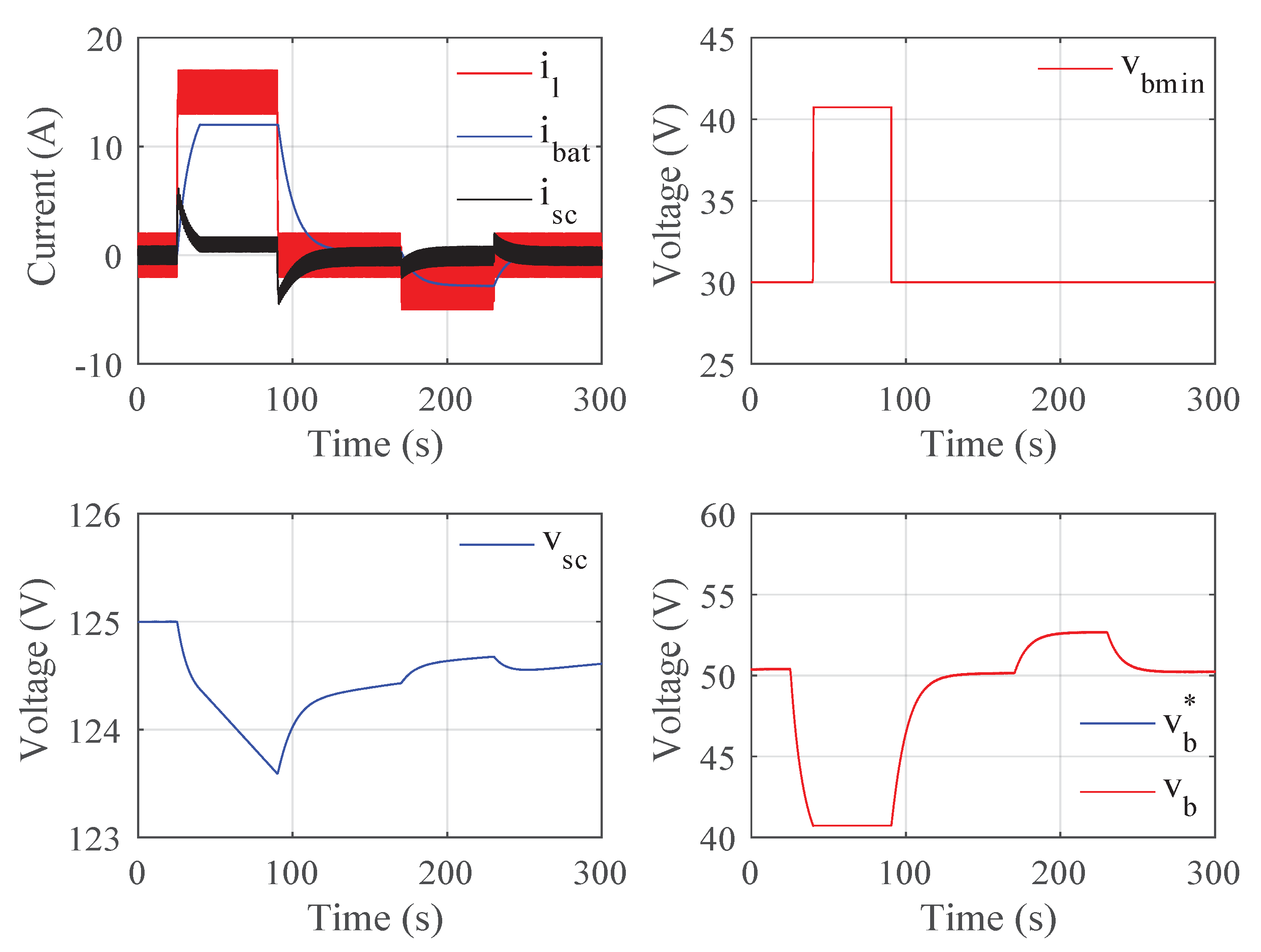
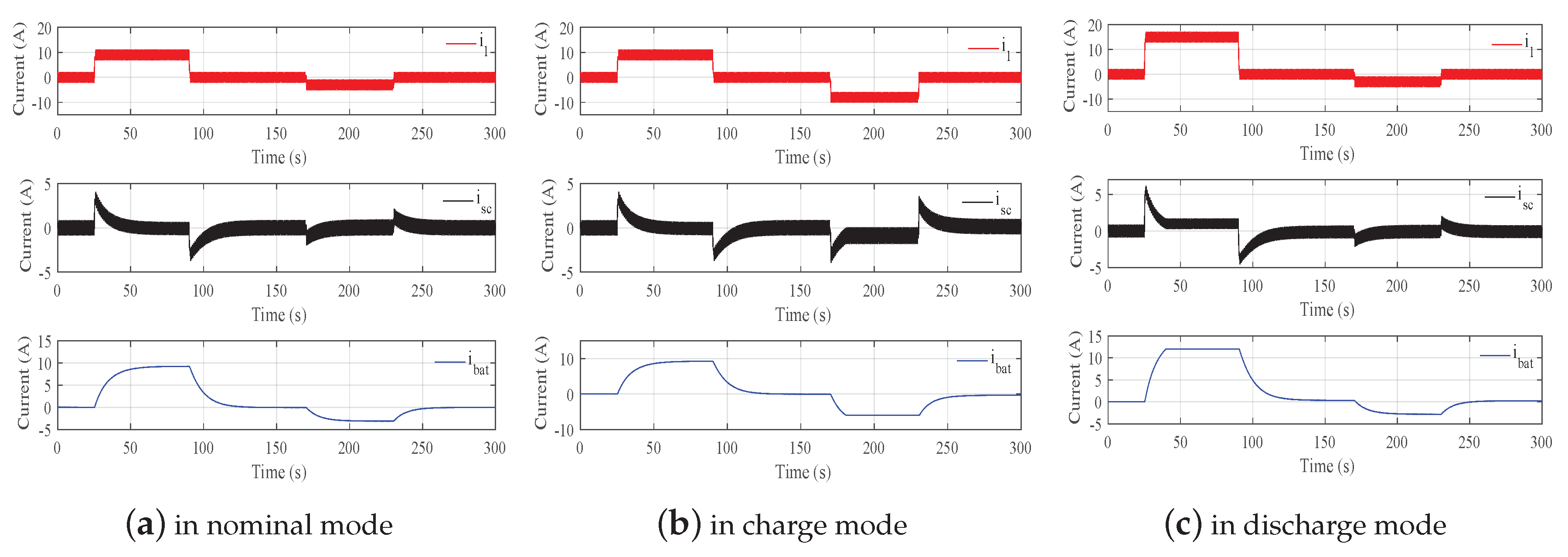
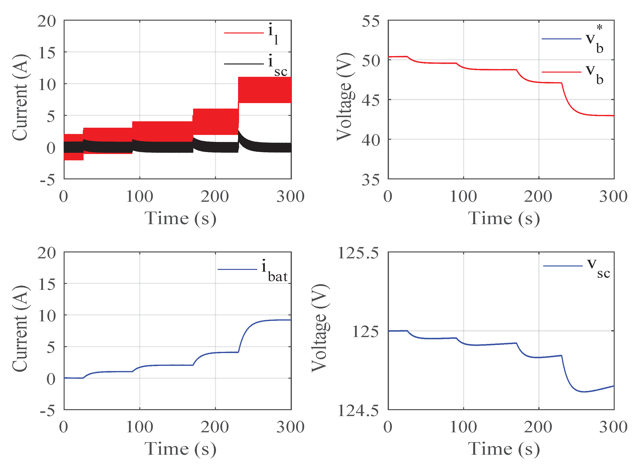
4.1. Simulation of the Proposed Control Strategy under Three Operation Modes

The simulation results of the proposed control strategy under nominal, charge and discharge mode are shown in Figure 5, Figure 6 and Figure 7, respectively. From Section 2, the degradation estimation of the battery was made via the model-driven method on the basis of the degradation model and CKF method. According to this estimation method, the internal resistance value of the battery under each SOC condition during the battery degradation process could be obtained. Considering the moment when the SOC of the battery after long-time degradation was 100% as shown in Figure 2, the internal resistance estimation value of a single battery cell was about 0.06714 Ω , which was adopted in this simulation part.
As shown in Figure 5, in nominal mode, the value of all the currents and voltages was in the allowed range. Therefore, there was no change in the dynamic thresholds of the DC bus voltage, and the anti-windup scheme was not activated.
As shown in Figure 6, in charge mode, the battery current reached the maximum limit value at the time of 170 s, which caused the decrease of the dynamic maximum threshold of the DC bus voltage for security consideration. Meanwhile, the anti-windup scheme was activated so as to protect the battery.
As shown in Figure 7, in discharge mode, the battery current reached the minimum limit value at the time of 25 s, which caused the increase of the dynamic maximum threshold of the DC bus voltage in order to ensure the safety of the battery. Similarly, as the case in charge mode, the anti-windup scheme was activated as well.
In Figure 8, the simulation results of the battery current, supercapacitors’ current, and load current with perturbations are presented under these three operation modes. It can be found obviously that the supercapacitors provided the transient current with fast dynamics when there was a sudden change in load. Moreover, the supercapacitors absorbed the transient and sinusoidal perturbations efficiently so as to smooth the behavior of the battery current.

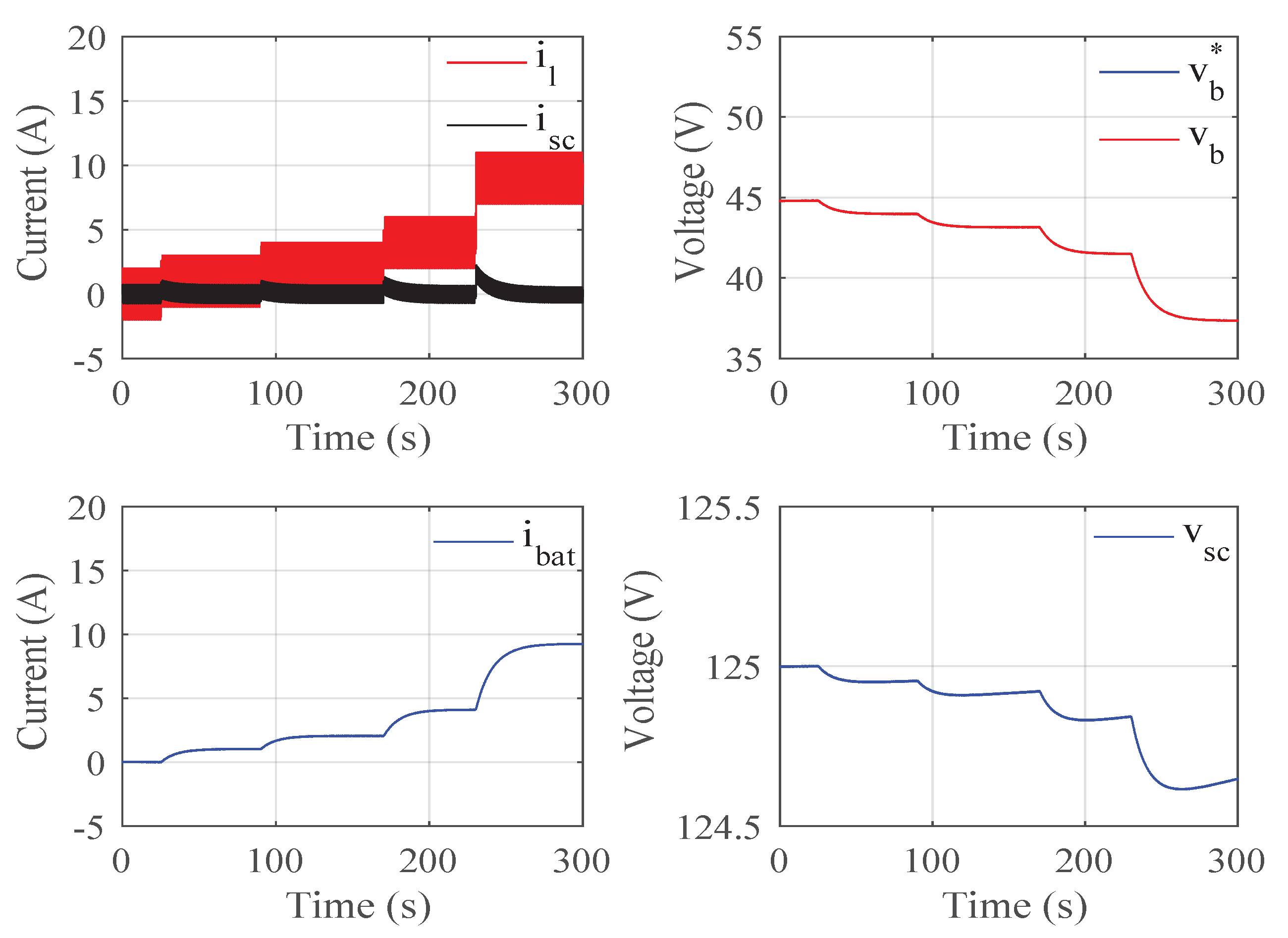
4.2. Simulation of the Proposed Control Strategy with Different SOC Conditions

In order to validate the effectiveness of the proposed control method considering battery degradation in different SOC conditions, the simulation and analysis are done in this part. According to Section 2, the degradation estimation results of the battery were obtained as shown in Figure 2.
Considering after long-time degradation, the battery was in Discharge Cycle 168. During this discharge cycle, the battery SOC would decrease from 100%, the internal resistance of battery would increase, and the voltage of the battery would decrease. The simulation results of the 100% SOC, 65% SOC, and 30% SOC conditions are shown in Figure 9, Figure 10 and Figure 11, respectively.
In Figure 9, the simulation results of the 100% SOC condition are presented. When the load current increased abruptly, supercapacitors discharged rapidly in order to offer the transient power. Then, the battery with low dynamics supplied the main power. Moreover, due to the adoption of the proposed control method, the voltage oscillations on the DC bus were attenuated to a large extent, which could ensure the smooth behavior of the battery current and increase the lifespan of the battery.
Figure 10 and Figure 11 present the simulation results of the 65% SOC and 30% SOC conditions, respectively. In order to analyze the results of different SOC conditions easily, the load current was the same in this simulation work.
It can be seen from Figure 10 and Figure 11 obviously that the difference between these two SOC conditions and the previous 100% SOC condition occurred only in the value of the DC bus voltage due to the increase of internal battery resistance and the decrease of battery voltage caused by the degradation of the battery. In the 65% SOC condition, the value of the DC bus voltage decreased from 44.8 V, and in the 30% SOC condition, the value of DC bus voltage decreased from 42.5 V, while in the 100% SOC condition, the value of the DC bus voltage decreased from 50.4 V. For battery current, supercapacitors’ current, and voltage, their behaviors were the same no matter in which SOC condition they were. Therefore, the effectiveness of the proposed control strategy with different SOC conditions was validated.

4.3. Comparison Analysis of the Proposed Control Strategy with the Method of Two PI Controllers

In order to make a comparison between the proposed control strategy and the traditional control method on the basis of two PI controllers, the simulations of two PI controllers for this hybrid power system were done as well. In other words, the simulations were done after replacing the ST controller in the inner voltage loop by a traditional PI controller, and the outer voltage loop adopted the PI controller still.
Figure 12 presents the main comparison results of battery current in nominal mode, charge mode, and discharge mode. As shown in the zoomed in detail in Figure 12, the oscillations of the red curve were obviously smaller than the blue curve. That is to say, the battery current of the proposed method was obviously smoother than the method of two PI controllers, which benefited increasing the lifespan of the battery. Therefore, the proposed control strategy based on one ST controller and one PI controller operated like a low-pass filter effectively and was better than the method based on two PI controllers to a large extent.

5. Conclusions

In this paper, a disturbance rejection control strategy for a hybrid power system considering the degradation of the battery was developed. The paper first made the degradation estimation of the battery based on the battery degradation model and Cubature Kalman Filter method. Then, the control strategy was proposed on the basis of the super twisting controller and proportional integral controller with some constraints integrated in the anti-windup scheme. Finally, the effectiveness of the proposed control strategy was verified via simulation work.
The novelty and main contributions of this paper were as follows: Firstly, this paper was the first to propose a robust control strategy that adopted the super twisting controller in the inner voltage loop to operate like a low-pass filter for such a single converter hybrid battery/supercapacitor system, in order to reject the disturbance and attenuate the perturbations on the DC bus. Secondly, the proposed control method worked well when the degradation of the battery was taken into account in such a hybrid electrical system, while many other researchers have not considered this battery degradation phenomenon in previous control research. Thirdly, this paper took into account the practical situation for limiting the battery current and supercapacitors’ current, and some constraints were implemented in the anti-windup schemes in the cascaded control loop. Therefore, the proposed method has application value in a practical hybrid battery/supercapacitor system to some extent.
In future research work, the experimental research will be carried out based on hardware-in-the-loop tests. Then, in order to avoid the gains being overestimated in the practical system, the current control method will be considered to be improved by designing an adaptive super twisting controller so that the control gains will be adaptive instead of constant. In addition, more than two types of power sources will be considered. A more complex hybrid power system that consists of a fuel cell, battery, and supercapacitors will be studied in future research.

Author Contributions

Conceptualization, Y.Z., H.O., S.L., M.H., and A.D.; methodology, Y.Z., H.O., and S.L.; software, Y.Z.; validation, Y.Z. and H.O.; formal analysis, Y.Z., H.O., and S.L.; investigation, Y.Z., H.O., S.L., M.H., and A.D.; resources, S.L., M.H., and A.D.; writing, original draft preparation, Y.Z. and H.O.; writing, review and editing, S.L., M.H., and A.D.; visualization, Y.Z. and H.O.; supervision, S.L., M.H., and A.D. All authors have read and agreed to the published version of the manuscript.

Funding

This research was funded by the China Scholarship Council (CSC) for the PhD student support.

Conflicts of Interest

The authors declare no conflict of interest.

Abbreviations

The following abbreviations are used in this manuscript:
CKFCubature Kalman Filter
STSuper Twisting
PIProportional Integral
SOCState Of Charge
OCVOpen Circuit Voltage
APEAbsolute Percentage Error

Appendix A

Figure A1. Battery voltage for different discharge cycles.
Energies 13 02781 g0a1
Figure A2. Battery OCV and SOC.
Energies 13 02781 g0a2

Appendix B

The main calculation steps of CKF are as follows:
(1)
Initialization: initialize the system state and covariance:
x ^ 0 = E [ x 0 ] , P 0 = V a r [ x 0 ]
(2)
Cubature points’ calculation:
P k = S k S k T
x k i = S k γ i + x ^ k , i = 1 , 2 , , 2 n
where n is the dimension of the state variable and γ i is a set of cubature points.
γ i = n E i , i = 1 , 2 , , n n E i , i = n + 1 , n + 2 , , 2 n
where E i is a unit matrix.
(3)
Cubature points’ propagation:
x k + 1 | k i = f ( x k i , u k )
(4)
State prediction:
x ^ k + 1 | k = 1 2 n i = 1 2 n x k + 1 | k i
p ¯ k = 1 2 n i = 1 2 n x k + 1 | k i ( x k + 1 | k i ) T x ^ k + 1 | k ( x ^ k + 1 | k ) T + Q
(5)
Cubature points’ calculation:
p ¯ k = S k + 1 | k S k + 1 | k T
X k + 1 | k i = S k + 1 | k γ i + x ^ k + 1 | k
(6)
Cubature points’ propagation:
y k + 1 i = h ( X k + 1 | k i , u k )
(7)
Measurement update:
y ^ k + 1 = 1 2 n i = 1 2 n y k + 1 i
p y y = 1 2 n i = 1 2 n y k + 1 i ( y k + 1 i ) T y ^ k + 1 y ^ k + 1 T + R
p x y = 1 2 n i = 1 2 n X k + 1 | k i ( y k + 1 i ) T x ^ k + 1 | k y ^ k + 1 T
(8)
The state and covariance update: update the Kalman gain K , the state x ^ k + 1 , and covariance P k + 1 :
K = p x y p y y 1
x ^ k + 1 = x ^ k + 1 | k + K ( y k + 1 y ^ k + 1 )
P k + 1 = p ¯ k K p y y K T

References

  1. Andwari, A.M.; Pesiridis, A.; Rajoo, S.; Martinez-Botas, R.; Esfahanian, V. A review of Battery Electric Vehicle technology and readiness levels. Renew. Sustain. Energy Rev. 2017, 78, 414–430. [Google Scholar] [CrossRef]
  2. Campi, T.; Cruciani, S.; Maradei, F.; Feliziani, M. Magnetic Field during Wireless Charging in an Electric Vehicle According to Standard SAE J2954. Energies 2019, 12, 1795. [Google Scholar] [CrossRef] [Green Version]
  3. Faessler, B.; Schuler, M.; Preißinger, M.; Kepplinger, P. Battery storage systems as grid-balancing measure in low-voltage distribution grids with distributed generation. Energies 2017, 10, 2161. [Google Scholar] [CrossRef] [Green Version]
  4. Liu, L.; Kong, F.; Liu, X.; Peng, Y.; Wang, Q. A review on electric vehicles interacting with renewable energy in smart grid. Renew. Sustain. Energy Rev. 2015, 51, 648–661. [Google Scholar] [CrossRef]
  5. Wang, Q.; Mao, B.; Stoliarov, S.I.; Sun, J. A review of lithium ion battery failure mechanisms and fire prevention strategies. Prog. Energy Combust. Sci. 2019, 73, 95–131. [Google Scholar] [CrossRef]
  6. Solanke, T.U.; Ramachandaramurthy, V.K.; Yong, J.Y.; Pasupuleti, J.; Kasinathan, P.; Rajagopalan, A. A review of strategic charging–discharging control of grid-connected electric vehicles. J. Energy Storage 2020, 28, 101193. [Google Scholar] [CrossRef]
  7. Moncecchi, M.; Brivio, C.; Mandelli, S.; Merlo, M. Battery Energy Storage Systems in Microgrids: Modeling and Design Criteria. Energies 2020, 13, 2006. [Google Scholar] [CrossRef] [Green Version]
  8. Marzougui, H.; Amari, M.; Kadri, A.; Bacha, F.; Ghouili, J. Energy management of fuel cell/battery/ultracapacitor in electrical hybrid vehicle. Int. J. Hydrog. Energy 2017, 42, 8857–8869. [Google Scholar] [CrossRef]
  9. Lencwe, M.J.; Chowdhury, S.P.; Olwal, T.O. A multi-stage approach to a hybrid lead acid battery and supercapacitor system for transport vehicles. Energies 2018, 11, 2888. [Google Scholar] [CrossRef] [Green Version]
  10. Vinot, E.; Trigui, R. Optimal energy management of HEVs with hybrid storage system. Energy Convers. Manag. 2013, 76, 437–452. [Google Scholar] [CrossRef] [Green Version]
  11. Zhang, C.; Wang, D.; Wang, B.; Tong, F. Battery Degradation Minimization-Oriented Hybrid Energy Storage System for Electric Vehicles. Energies 2020, 13, 246. [Google Scholar] [CrossRef] [Green Version]
  12. Ali, M.U.; Zafar, A.; Nengroo, S.H.; Hussain, S.; Park, G.S.; Kim, H.J. Online Remaining Useful Life Prediction for Lithium-Ion Batteries Using Partial Discharge Data Features. Energies 2019, 12, 4366. [Google Scholar] [CrossRef] [Green Version]
  13. Ali, M.U.; Kamran, M.A.; Kumar, P.S.; Nengroo, S.H.; Khan, M.A.; Hussain, A.; Kim, H.J. An online data-driven model identification and adaptive state of charge estimation approach for lithium-ion-batteries using the lagrange multiplier method. Energies 2018, 11, 2940. [Google Scholar] [CrossRef] [Green Version]
  14. Hannan, M.A.; Lipu, M.H.; Hussain, A.; Mohamed, A. A review of lithium-ion battery state of charge estimation and management system in electric vehicle applications: Challenges and recommendations. Renew. Sustain. Energy Rev. 2017, 78, 834–854. [Google Scholar] [CrossRef]
  15. Yang, B.; Wang, J.; Zhang, X.; Wang, J.; Shu, H.; Li, S.; He, T.; Lan, C.; Yu, T. Applications of battery/supercapacitor hybrid energy storage systems for electric vehicles using perturbation observer based robust control. J. f Power Sources 2020, 448, 227444. [Google Scholar] [CrossRef]
  16. Wang, Y.; Yang, Z.; Li, F. Optimization of energy management strategy and sizing in hybrid storage system for tram. Energies 2018, 11, 752. [Google Scholar] [CrossRef] [Green Version]
  17. Miniguano, H.; Barrado, A.; Fernández, C.; Zumel, P.; Lázaro, A. A General Parameter Identification Procedure Used for the Comparative Study of Supercapacitors Models. Energies 2019, 12, 1776. [Google Scholar] [CrossRef] [Green Version]
  18. Kouchachvili, L.; Yaïci, W.; Entchev, E. Hybrid battery/supercapacitor energy storage system for the electric vehicles. Journal of Power Sources 2018, 374, 237–248. [Google Scholar] [CrossRef]
  19. Hilairet, M.; Bethoux, O.; Azib, T.; Talj, R. Interconnection and damping assignment passivity-based control of a fuel cell system. In Proceedings of the IEEE International Symposium on Industrial Electronics, Bari, Italy, 4–7 July 2010; pp. 219–224. [Google Scholar]
  20. Azib, T.; Bethoux, O.; Remy, G.; Marchand, C. Structure and control strategy for a parallel hybrid fuel cell/supercapacitors power source. In Proceedings of the IEEE Vehicle Power and Propulsion Conference, Dearborn, MI, USA, 7–10 September 2009; pp. 1858–1863. [Google Scholar]
  21. Bambang, R.T.; Rohman, A.S.; Dronkers, C.J.; Ortega, R.; Sasongko, A. Energy management of fuel cell/battery/supercapacitor hybrid power sources using model predictive control. IEEE Trans. Ind. Inform. 2014, 10, 1992–2002. [Google Scholar]
  22. Kong, S.; Hilairet, M.; Roche, R. Passivity-Based Control for a PV/Battery/Fuel Cell/Electrolyser Hybrid Power System. In Proceedings of the IEEE Milan PowerTech, Milan, Italy, 23–27 June 2019; pp. 1–6. [Google Scholar]
  23. Mohammedi, M.; Kraa, O.; Becherif, M.; Aboubou, A.; Ayad, M.; Bahri, M. Fuzzy logic and passivity-based controller applied to electric vehicle using fuel cell and supercapacitors hybrid source. Energy Procedia 2014, 50, 619–626. [Google Scholar] [CrossRef] [Green Version]
  24. Zhang, H.; Liu, X.; Ji, H.; Hou, Z.; Fan, L. Multi-Agent-Based Data-Driven Distributed Adaptive Cooperative Control in Urban Traffic Signal Timing. Energies 2019, 12, 1402. [Google Scholar] [CrossRef] [Green Version]
  25. Hou, Z.; Chi, R.; Gao, H. An overview of dynamic-linearization-based data-driven control and applications. IEEE Trans. Ind. Electron. 2016, 64, 4076–4090. [Google Scholar] [CrossRef]
  26. Hou, Z.S.; Wang, Z. From model-based control to data-driven control: Survey, classification and perspective. Inf. Sci. 2013, 235, 3–35. [Google Scholar] [CrossRef]
  27. Roman, R.C.; Precup, R.E.; Bojan-Dragos, C.A.; Szedlak-Stinean, A.I. Combined Model-Free Adaptive Control with Fuzzy Component by Virtual Reference Feedback Tuning for Tower Crane Systems. Procedia Comput. Sci. 2019, 162, 267–274. [Google Scholar] [CrossRef]
  28. Hou, Z.; Jin, S. A novel data-driven control approach for a class of discrete-time nonlinear systems. IEEE Trans. Control Syst. Technol. 2010, 19, 1549–1558. [Google Scholar] [CrossRef]
  29. Yoshio, M.; Brodd, R.J.; Kozawa, A. Lithium-Ion Batteries; Springer: Berlin/Heidelberg, Germany, 2009; Volume 1. [Google Scholar] [CrossRef]
  30. Jin, X.; Vora, A.; Hoshing, V.; Saha, T.; Shaver, G.; Wasynczuk, O.; Varigonda, S. Applicability of available Li-ion battery degradation models for system and control algorithm design. Control Eng. Pract. 2018, 71, 1–9. [Google Scholar] [CrossRef]
  31. Li, J.; Landers, R.G.; Park, J. A comprehensive single-particle-degradation model for battery state-of-health prediction. J. Power Sources 2020, 456, 227950. [Google Scholar] [CrossRef]
  32. Park, J.; Lee, M.; Kim, G.; Park, S.; Kim, J. Integrated Approach Based on Dual Extended Kalman Filter and Multivariate Autoregressive Model for Predicting Battery Capacity Using Health Indicator and SOC/SOH. Energies 2020, 13, 2138. [Google Scholar] [CrossRef]
  33. Wang, F.K.; Mamo, T. A hybrid model based on support vector regression and differential evolution for remaining useful lifetime prediction of lithium-ion batteries. J. Power Sources 2018, 401, 49–54. [Google Scholar] [CrossRef]
  34. Chen, L.; Xu, L.; Zhou, Y. Novel approach for lithium-ion battery on-line remaining useful life prediction based on permutation entropy. Energies 2018, 11, 820. [Google Scholar] [CrossRef] [Green Version]
  35. Tang, X.; Yao, K.; Liu, B.; Hu, W.; Gao, F. Long-term battery voltage, power, and surface temperature prediction using a model-based extreme learning machine. Energies 2018, 11, 86. [Google Scholar] [CrossRef] [Green Version]
  36. Abdulla, K.; De Hoog, J.; Muenzel, V.; Suits, F.; Steer, K.; Wirth, A.; Halgamuge, S. Optimal operation of energy storage systems considering forecasts and battery degradation. IEEE Trans. Smart Grid 2016, 9, 2086–2096. [Google Scholar] [CrossRef]
  37. Wang, D.; Coignard, J.; Zeng, T.; Zhang, C.; Saxena, S. Quantifying electric vehicle battery degradation from driving vs. vehicle-to-grid services. J. Power Sources 2016, 332, 193–203. [Google Scholar] [CrossRef] [Green Version]
  38. Li, X.; Wang, Z.; Yan, J. Prognostic health condition for lithium battery using the partial incremental capacity and Gaussian process regression. J. Power Sources 2019, 421, 56–67. [Google Scholar] [CrossRef]
  39. Li, H.; Ravey, A.; N’Diaye, A.; Djerdir, A. Online adaptive equivalent consumption minimization strategy for fuel cell hybrid electric vehicle considering power sources degradation. Energy Convers. Manag. 2019, 192, 133–149. [Google Scholar] [CrossRef]
  40. Laghrouche, S.; Harmouche, M.; Chitour, Y. Higher order super-twisting for perturbed chains of integrators. IEEE Trans. Autom. Control 2017, 62, 3588–3593. [Google Scholar] [CrossRef] [Green Version]
  41. Fridman, L.; Galván-Guerra, R.; Velázquez-Velázquez, J.E.; Iriarte, R. Sliding Modes for Switched Uncertain Linear Time Invariant Systems: An Output Integral Sliding Mode Approach. In New Perspectives and Applications of Modern Control Theory; Springer: Berlin/Heidelberg, Germany, 2018; pp. 153–185. [Google Scholar] [CrossRef]
  42. Fridman, L.; Plestan, F.; Barbot, J.P. Recent Trends in Sliding Mode Control; IET Digital Library: London, UK, 2016. [Google Scholar] [CrossRef]
  43. Pérez-Ventura, U.; Fridman, L. Design of super-twisting control gains: A describing function based methodology. Automatica 2019, 99, 175–180. [Google Scholar] [CrossRef]
  44. Sanchez, T.; Moreno, J.A.; Fridman, L.M. Output feedback continuous twisting algorithm. Automatica 2018, 96, 298–305. [Google Scholar] [CrossRef]
  45. Torres-González, V.; Sanchez, T.; Fridman, L.M.; Moreno, J.A. Design of continuous twisting algorithm. Automatica 2017, 80, 119–126. [Google Scholar] [CrossRef]
  46. Boiko, I.M. On frequency-domain criterion of finite-time convergence of second-order sliding mode control algorithms. Automatica 2011, 47, 1969–1973. [Google Scholar] [CrossRef]
  47. Shtessel, Y.B.; Shkolnikov, I.A.; Levant, A. Smooth second-order sliding modes: Missile guidance application. Automatica 2007, 43, 1470–1476. [Google Scholar] [CrossRef]
  48. Saha, B.; Goebel, K. Battery Data Set. NASA Ames Research Center. 2007. Available online: https://ti.arc.nasa.gov/tech/dash/groups/pcoe/prognostic-data-repository/ (accessed on 29 May 2020).
  49. He, W.; Williard, N.; Chen, C.; Pecht, M. State of charge estimation for electric vehicle batteries using unscented kalman filtering. Microelectron. Reliab. 2013, 53, 840–847. [Google Scholar] [CrossRef]
  50. Luo, J.; Peng, J.; He, H. Lithium-ion battery SOC estimation study based on cubature Kalman filter. Energy Procedia 2019, 158, 3421–3426. [Google Scholar] [CrossRef]
  51. Wang, J.; Zhang, D.; Shao, X. New version of continuous–discrete cubature Kalman filtering for nonlinear continuous–discrete systems. ISA Trans. 2019, 91, 174–183. [Google Scholar] [CrossRef]
  52. Peng, J.; Luo, J.; He, H.; Lu, B. An improved state of charge estimation method based on cubature Kalman filter for lithium-ion batteries. Appl. Energy 2019, 253, 113520. [Google Scholar] [CrossRef]
  53. Levant, A. Sliding order and sliding accuracy in sliding mode control. Int. J. Control 1993, 58, 1247–1263. [Google Scholar] [CrossRef]
  54. Levant, A. Higher-order sliding modes, differentiation and output-feedback control. Int. J. Control 2003, 76, 924–941. [Google Scholar] [CrossRef]
  55. Barth, A.; Reichhartinger, M.; Reger, J.; Horn, M.; Wulff, K. Lyapunov-design for a super-twisting sliding-mode controller using the certainty-equivalence principle. IFAC-PapersOnLine 2015, 48, 860–865. [Google Scholar] [CrossRef]
  56. Orlov, Y. Finite time stability and robust control synthesis of uncertain switched systems. SIAM J. Control Optim. 2004, 43, 1253–1271. [Google Scholar] [CrossRef]
Figure 1. Battery degradation model.
Energies 13 02781 g001
Figure 2. Degradation estimation of battery: resistance estimation; SOC estimation; voltage estimation; APE of voltage estimation.
Energies 13 02781 g002
Figure 3. System topology and control structure.
Energies 13 02781 g003
Figure 4. Constraints of supercapacitors.
Energies 13 02781 g004
Figure 5. Simulation results, in nominal mode.
Energies 13 02781 g005
Figure 6. Simulation results, in charge mode.
Energies 13 02781 g006
Figure 7. Simulation results, in discharge mode.
Energies 13 02781 g007
Figure 8. Simulation results of the battery, supercapacitors’, and load currents with sinperturbations.
Energies 13 02781 g008
Figure 9. Simulation results: 100% SOC.
Energies 13 02781 g009
Figure 10. Simulation results: 65% SOC.
Energies 13 02781 g010
Figure 11. Simulation results: 30% SOC.
Energies 13 02781 g011
Figure 12. Comparison result of the proposed method with two PI controllers.
Energies 13 02781 g012

