Real-Time Control Based on a CAN-Bus of Hybrid Electrical Systems †


1
FEMTO-ST Institute, Univ. Bourgogne Franche-Comté, CNRS, Rue Ernest Thierry Mieg, F-90010 Belfort, France
2
FCLAB, Univ. Bourgogne Franche-Comté, CNRS Rue Ernest Thierry Mieg, F-90010 Belfort, France
3
Clean Horizon Consulting, 12 Rue de la Chaussée d’Antin, 75009 Paris, France
*
Author to whom correspondence should be addressed.
†
This paper is an extended version of our paper published in 2015 IEEE Vehicle Power and Propulsion Conference (VPPC), Montreal, QC, Canada, 19–22 October 2015; pp. 1–6.
Energies 2020, 13(17), 4502; https://0-doi-org.brum.beds.ac.uk/10.3390/en13174502
Submission received: 1 July 2020
/
Revised: 30 July 2020
/
Accepted: 31 July 2020
/
Published: 1 September 2020
(This article belongs to the Special Issue Design, Diagnosis and Control and Social Acceptance of Battery, Solar Cell and Fuel Cell System)
Abstract
:Power management of a one-converter parallel structure with battery and supercapacitor is addressed in this paper. The controller is implemented on a DSP from a Microchip and uses a Controller Area Network (CAN) bus communication for data exchange. However, the low data transmission rate of the CAN bus data impacts the performances of regular power management strategies. This paper details an initial strategy with a charge sustaining mode for an application coupling a battery with supercapacitors, in which low performances have been witnessed due to the high sampling time of the CAN bus data. Therefore, a new strategy is proposed to tackle the sample time issue based on a depleting mode. Simulation and experimental results with a dsPIC33EP512MU810 DSP based on a 10 kW hybrid system proves the feasibility of the proposed approach.
1. Introduction
Many works based on hybrid electrical transport applications are performed essentially to face environmental issues. Most of the time, three kinds of hybridisation are pointed out: fuel cell (FC)/supercapacitors (SCs), fuel cell/battery (BT) or battery/supercapacitors [1,2,3,4,5,6,7,8,9,10,11] or more sources [12,13,14]. The connection of the power sources is subject to many power electronic topologies. Each of them has advantages and disadvantages regarding efficiency, flexibility, price, and weight. However, the main topologies are the one-converter or the two-converter hybrid structures. The key-point of such hybrid systems is the suitable energy management allowing a reliable and effective behaviour of the sources [2].
Whatever the power electronic topology (one- or two-converter topology), the most widespread requirement leads to smooth power on the main power source. In the case of a fuel cells (FC)/supercapacitors (SCs) [15] or FC/battery (BT) [16] or BT/SCs [4] associations, the FC or BT are going to operate with low current transients in order to improve the durability of the main power source [17,18,19].
This work focuses on the one-converter-based hybrid power system associating BT and SCs for civil or military transportation applications and is intended to perform in compliance with real conditions. Batteries have been widely adopted as the main power source for full electric vehicles [20] for their high energy density [21]. In this work, a Lithium Ion Fer Phosphate (LiFePO4) battery was selected for its safety, good environmental compliance, long lifetime, high discharge current, high power density and cost effectiveness when compared to other mature technologies [22].
However, the high price and heaviness of the battery when compared to supercapacitors justify that batteries and supercapacitors can be interfaced in order to maximize the benefits of the two components, i.e., limit the cost and weight of the battery pack, nevertheless with an increase of the total volume [23]. Therefore, SCs are used as an assistant to the main source to deliver power during fast acceleration or braking, and also allows to limit the battery current and temperature by an appropriate assistance of the SCs during high current and high temperature of the battery pack. Moreover, the operation of the battery at high current needs to be avoid in order to impact positively the durability of the battery [20,24].
The implementation of these controllers is generally done with high-performance DSP/C with internal current/voltage controllers, PWM outputs to control the converters and its own current/voltage sensors. In such configuration, the implementation does not introduce issues. Nowadays, embedded and networked automotive bus communication such as the Controller Area Network (CAN) is widely used for vehicle networks. It is used for the communication between the controllers, the sensors and the actuators [25,26,27,28,29]. The controller can retrieve data from each component (i.e., voltage, current, temperature of the BT and SCs) and the DSP send periodic messages necessary to control the DC/DC converter [30,31,32,33]. It should be pointed out that the sampling frequency of the data on the CAN bus is relatively low compared to a regular implementation on a DSP/C that use analog inputs and the PWM peripherals [34]. In fact, in the case of a regular implementation, the CPU and the peripherals have a sampling time nearly equal to 100 μs for the inner current loops and nearly equal to 1ms for the outter voltage loops. Therefore, the performances of the controllers are not degraded by the sampling (see [3] for more information and [35,36] for theoretical details). In practice, the CAN bus data sampling frequency is defined by the manufacturers of top-of-the-shelf equipment and modifying it in a wide range is not always possible, at least in a range defined by the manufacturer.
It follows that designers need to face such issue by defining an appropriate controller with low data transmission rate [28]. Therefore, this paper aims to detail experimental knowledge about the power management of a hybrid system controlled by a Controller Area Network (CAN) bus communication where one fundamental issue to be addressed concerns the closed-loop control stability under sampling with such network control [29].
The main contribution of this paper is focused on the description of an initial strategy [37] with a charge-sustaining mode. Experimental results show that the proposed controlled [37] failed under high sampling time and quantization of the CAN bus data that deteriorate the closed-loop performances. It is the reason why a new rule-based strategy is proposed in this paper to tackle the sample time issue based on a depleting mode. Experimental results based on a 10 kW hybrid power pack coupling battery and supercapacitors prove the feasibility of the proposed approach.
The paper is organized as follows. In Section 2, a 10 kW experimental system is detailed. Section 3 details a regular controller for power management of a hybrid electrical system, where the closed-loop controller performance degradations are being emphasised with the CAN bus. Therefore, a sampled-data controller based on a charge depleting mode is described in Section 4, where experimental results are presented to show the effectiveness of the proposed controller.
2. Hybrid Power Pack Structure
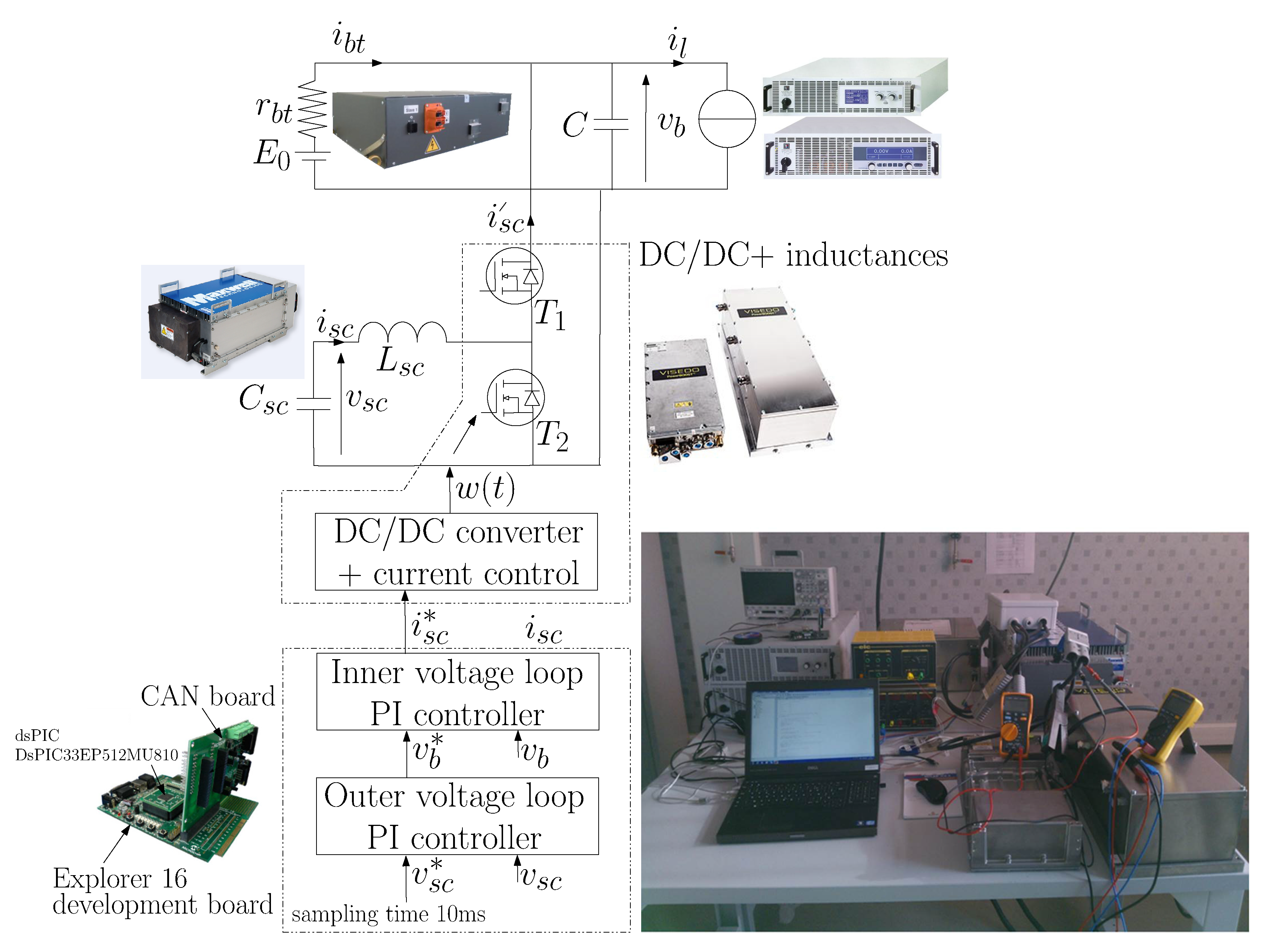
The hybrid power pack structure under study dedicated for civil or military applications is composed of a 3.84 kWh Lithium battery (LiFePO4, 48 V, 80 Ah) from E4V directly connected on the DC bus and supercapacitors (SCs) from Maxwell (BMOD0063P125B08, 125 V, 63 F). The SCs equipment is connected to the DC bus by an inverter from VISEDO (PowerBOOSTTM series DC/DC converter PBO-M-250-x, 250 kW max at 750 V with liquid cooling, set at 12 kW max without cooling and low DC voltage). The power electronic components are standard MOSFET modules and the PWM switching frequency is set at 4 kHz. The E4V battery have a CAN 2.0A protocol adjustable between 100 kbs and 500 kbs, while the PowerBOOST from VISEDO have CAN 2.0A or B with adjustable baud rate between 100 kbs and 1 Mbs.
The battery can provide 1C (80 A) during steady state without significant overheating, while 2C (160 A) during 10 min and 3C (240 A) during 40 s at early life of the battery pack and 23 C operation. As regular batteries, these data decrease over the time due to the cycling and the batterie temperature [38] and this knowledge can be integrated into the controller for a real-time update of the saturation functions. On another side, the SCs can provide 140 A during few minutes and thus can assist the battery during over-battery current to limit the battery temperature.
A programmable electronic load (EA-ELR 9080-510) and power source (EA-PSI 9080-340) from EA Elektro-Automatik are connected to the DC bus to emulate a reversible current source, i.e., emulate traction and regenerative mode. The electronic load has a rated power of 10.5 kW, 80 V can be obtained at low current and 510 A at low voltage always limited by the maximal nominal output power. The power source has a rated power of 10 kW, 80 V-340 A, same comment for the current/voltage/power limitations as the load. Finally, Figure 1 shows the experimental system and Table 1 gives the electric characteristics of the 10 kW hybrid system.
All the control and the monitoring data are transmitted by the battery and PowerBOOST converter through one CAN bus network. It is worth to mention that the VISEDO inverter integrates an internal current control loop, where the desired set point current of the SCs is transmitted through the CAN bus. The different nodes involved are the battery pack, the supercapacitors, the DC-DC converter and the reversible load (parallel coupling of a load and a power supply).
The three first variables of Table 2 are measurements (DC bus voltage , SCs voltage , battery current ) available on the target test bench. These data are obtained from the CAN bus according to the indicated features (sampling time, precision, data type). Using these variables regardless the load power requirement, the controller computes the output control variable of the SCs current () in order to manage the battery current and the state of charge of the SCs. It is important to mention that the sampling time, precision and data type of the measurements provided by these top of the shelf equipments cannot always be changed in a wide range (see Table 3). Thus, the behaviour of a continuous controller under sampling is not always reproducible. In fact, the sampling time requirement for regular power management controllers are nearly equal to 500 μs to 2 ms (see [3] for the performances degradation of continuous controllers under sampling). It means that the sampling time of the data coming from the components to control are nearly 100 times more important than the desired values. In such industrial case study, authors have face such issues by proposing an adequate rule-based controller.
The choice of the control board was done according to four criteria: portability, scalability, effectiveness and economical solution. Therefore, an Explorer 16 Development board from Microchip has been opted that allows to test various (16 or 32 bits) DSP and microcontroller. The dsPIC33EP512MU810 has been implemented for the reasons cited above associated with a PICtail Plus card interface for the CAN bus.
3. Regular Power Management
3.1. Problem Statement
Figure 1 represents a parallel power electronic system understudy composed of only one-converter. The controller is designed to provide a smooth current transition on the source with the lower current dynamic, namely the battery in this study. Also, the power between the battery and the SCs needs to be appropriately shared to match the power load requirement. The maximal currents of the battery and SCs, the state of charge (SoC) of the SCs, the battery temperature must be taken into account as constraints in the controller design [37]. This regular controller refers to charge-sustaining mode, where SCs assist the battery during power transient and the SoC of the SCs fluctuates but it is maintained at a certain level. Consequently, the control structure is based on three nested loops as shown in Figure 1, namely: (see [37] for details about the controller design):
- The VISEDO PowerBOOST have its internal current controller and the DSP transmits the supercapacitors current reference through the CAN (Controller Area Network) bus to the DC/DC converter.
- A PI inner voltage loop controller computes the supercapacitors current reference to maintain the DC bus voltage at the desired value.
- A PI outer voltage controller adjusts the DC bus reference voltage to control the SoC of the SCs and implicitly control the dynamic of the battery current. It is important to mention here that the DC bus of a one-converter structure need to fluctuate in order to change the battery current in comparison with a two-converters structure where the DC bus voltage is constant.
Finally, the two PI controllers are sampled at 10 ms which corresponds to the minimum sampling period to transmit the supercapacitors current reference through the CAN bus.
3.2. Experimental Results
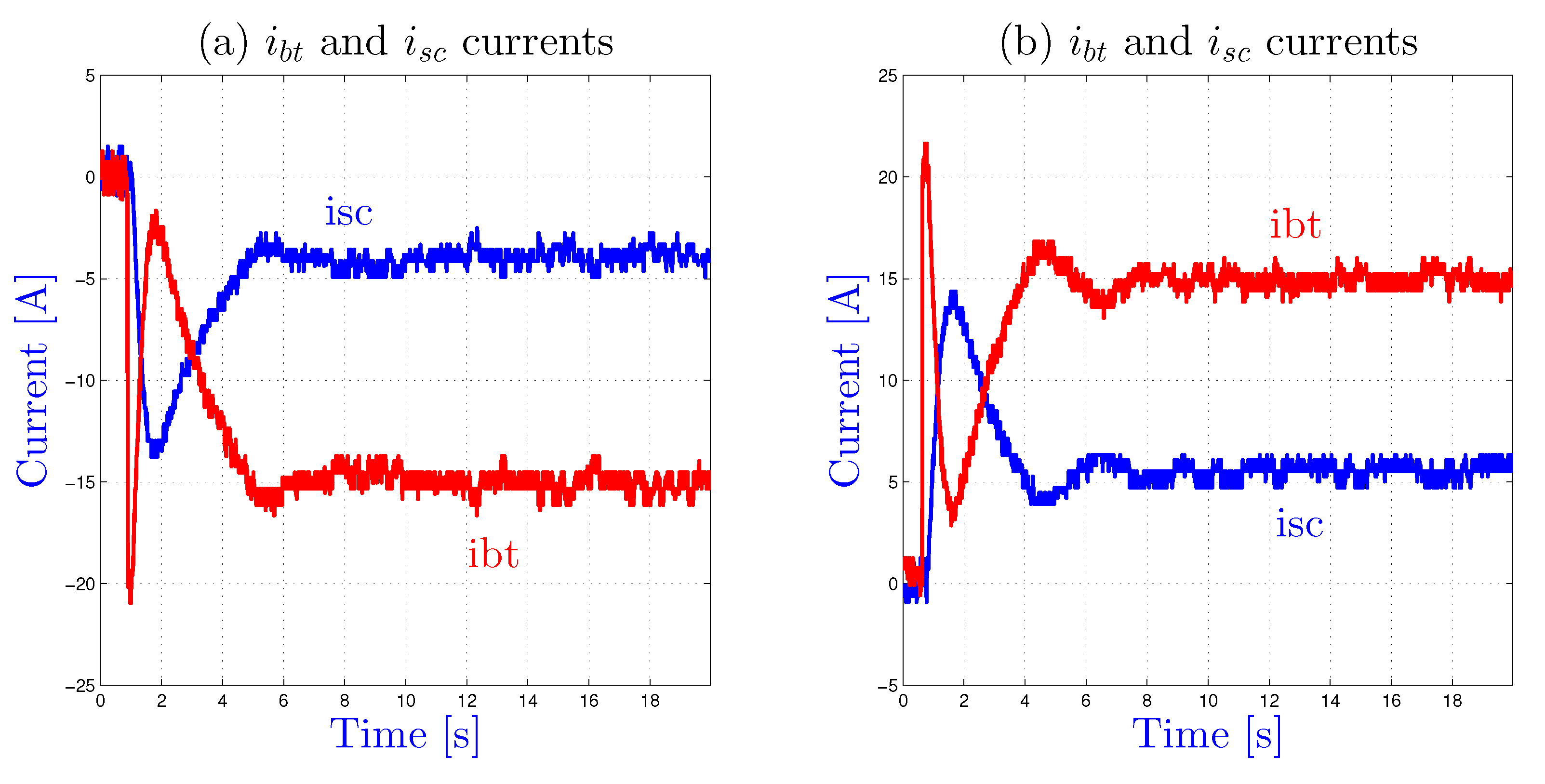
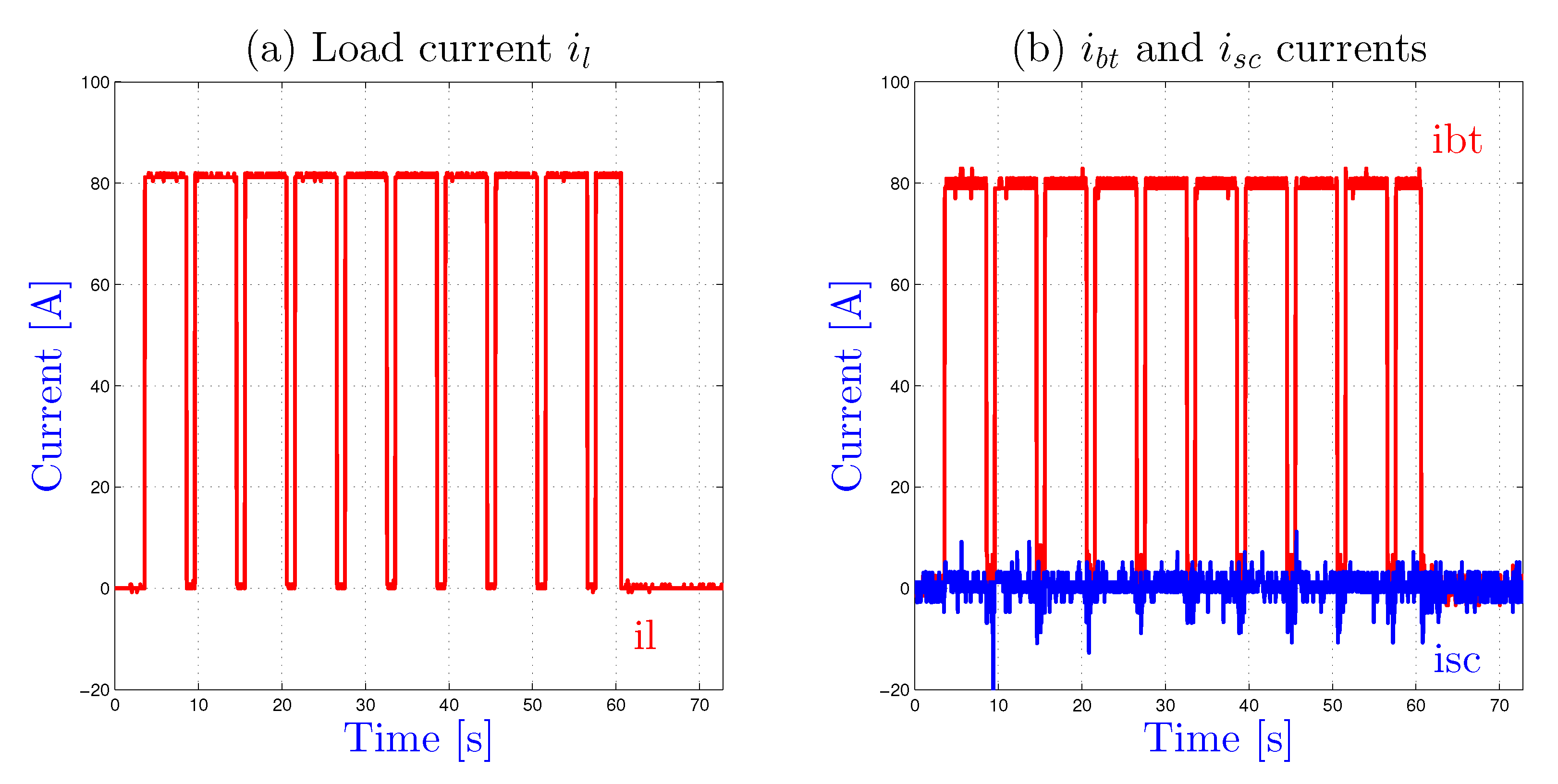
Figure 2 shows an experimental result for a nominal operation, i.e., a battery current lower than the maximum values. The battery provides current during the first part of the transient. Later, the SCs react during the second part and let the battery provide energy during the steady state.
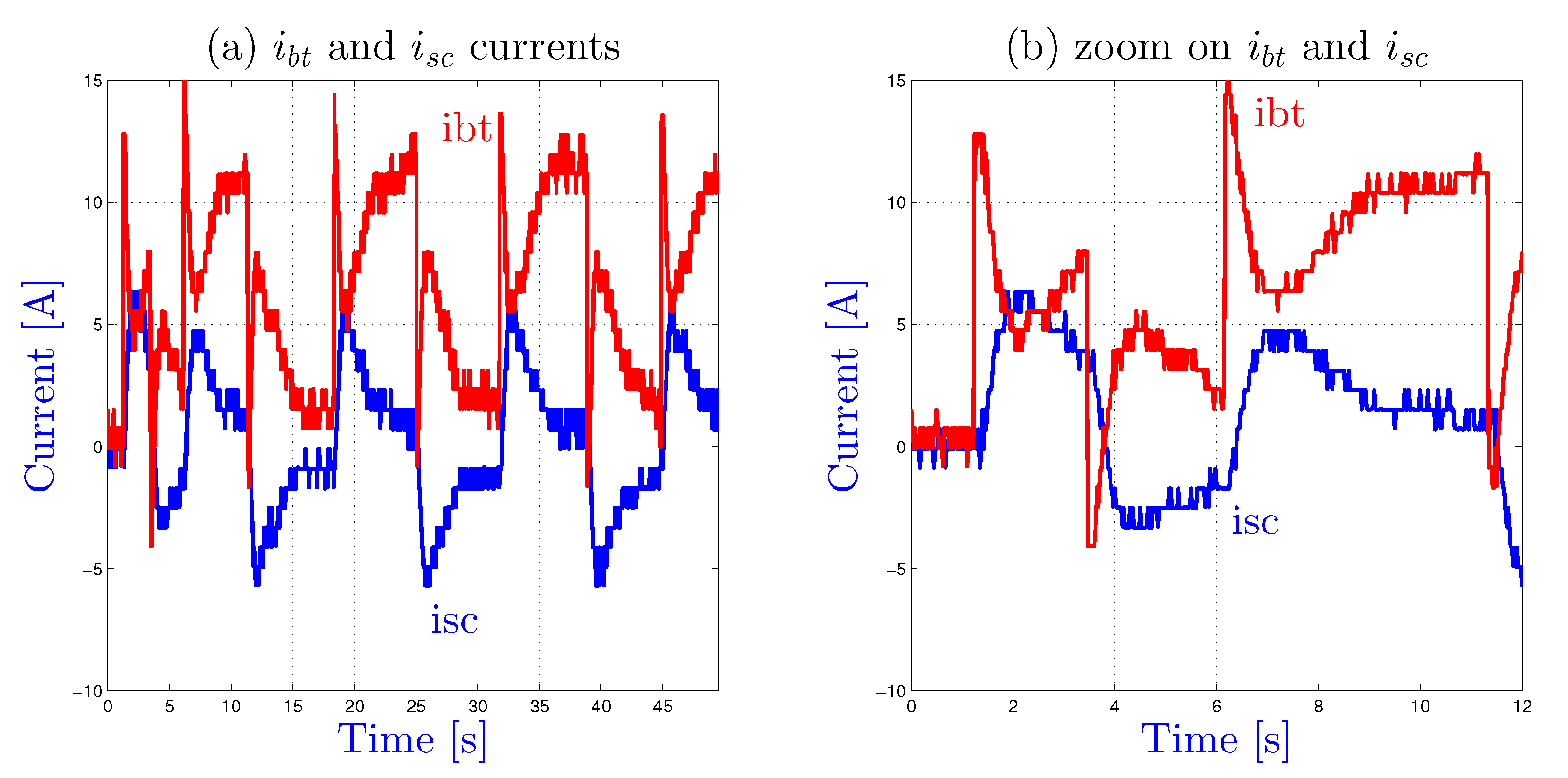
Figure 3 shows another experimental result when the battery current exceed the maximum values defined by the designer. In that case, the SCs assist the battery during the transient as in Figure 2 and continue to sustain the battery as long as the load current is greater (in absolute value) than the acceptable limits of the battery current. Here as an example, the maximum current of the battery have been fixed at −15 A during the charge mode (see Figure 3a) and +15 A during the discharge mode (see Figure 3b). The SCs absorb (or provide) the current that the battery could not absorb (or provide) in order to maintain the battery current at the desired value. As mentionned before, the knowledge of the number of cycling and the batterie temperature (obtained through the CAN bus) can be integrated into the controller to compute in real-time the maximum current of the battery for the saturation functions.
Experimental results show that the expected smoothing behaviour of the battery current is not fulfilled as shown in Figure 2 and Figure 3. Because the battery is connected in parallel to the DC bus without DC/DC converter and the periodic data sampling is too important, it turns out that the battery provide current during the first part of the transient until the SCs reacts. It follows an undesirable behaviour during load current transient. A analysis shows that the high sampling time of the transmit CAN frame data (109 ms, see data in Table 2) has been clearly identified as responsible for this unexpected behaviour.
3.3. Discussions
Experimental results have shown that the control of a one-converter structure with a CAN bus is not suitable and lead to such low performance results. Some of the solutions listed below are feasible:
- Components software modifications: The most effective solution consists on a software update of the sampling time of the data send by all the components at around 1 to 5 ms if this option is allowed. This option lead to good performances of the hybrid system.
- Additional sensors: If the first solution is not feasible for top of the self-equipment, additional current and voltage sensors associated with local microcontrollers can be added. This option leads to a flexible solution for the designer but increase the cost and reduce the reliability due to additional materials.
- Additional converter: A two-converters structure is probably an effective solution is such configuration because it allows a separate control of the two current sources and therefore doesn’t lead to high battery peak current during load current transient. However, this solution increases the cost, weight, volume and decrease the efficiency and reliability.
All the above solutions have been rejected since these top of the self-equipements can not be updated and the addition of sensors increase the cost and reduce the reliability. Therefore an alternative controller has been under study base on a rule charge depleting operation.
4. Charge Depleting Mode with Soc Recovering of the Scs
4.1. Problem Statement
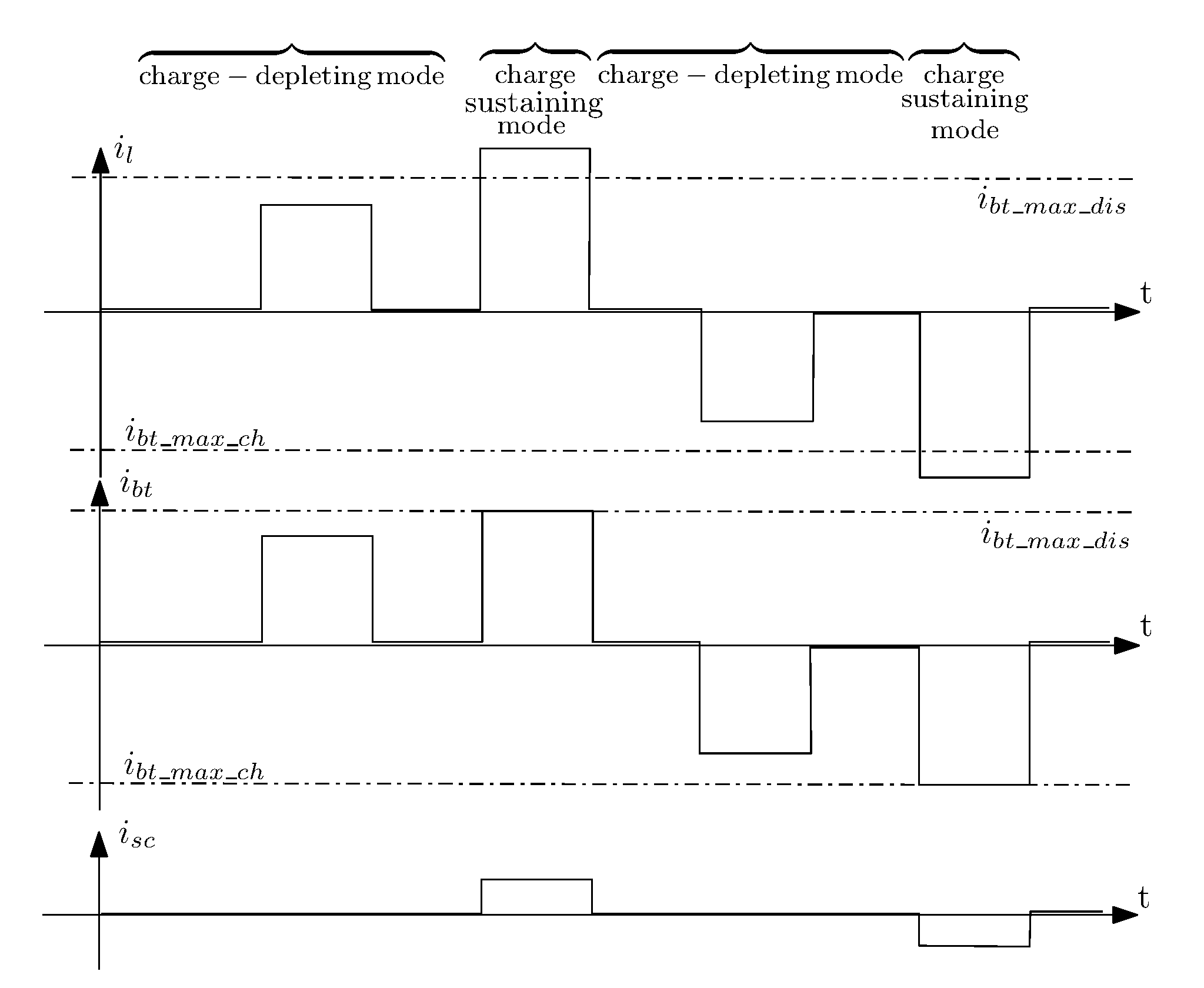
The proposed controller switch between a charge depleting and a charge-sustaining modes according to the maximum current allowed for the battery:
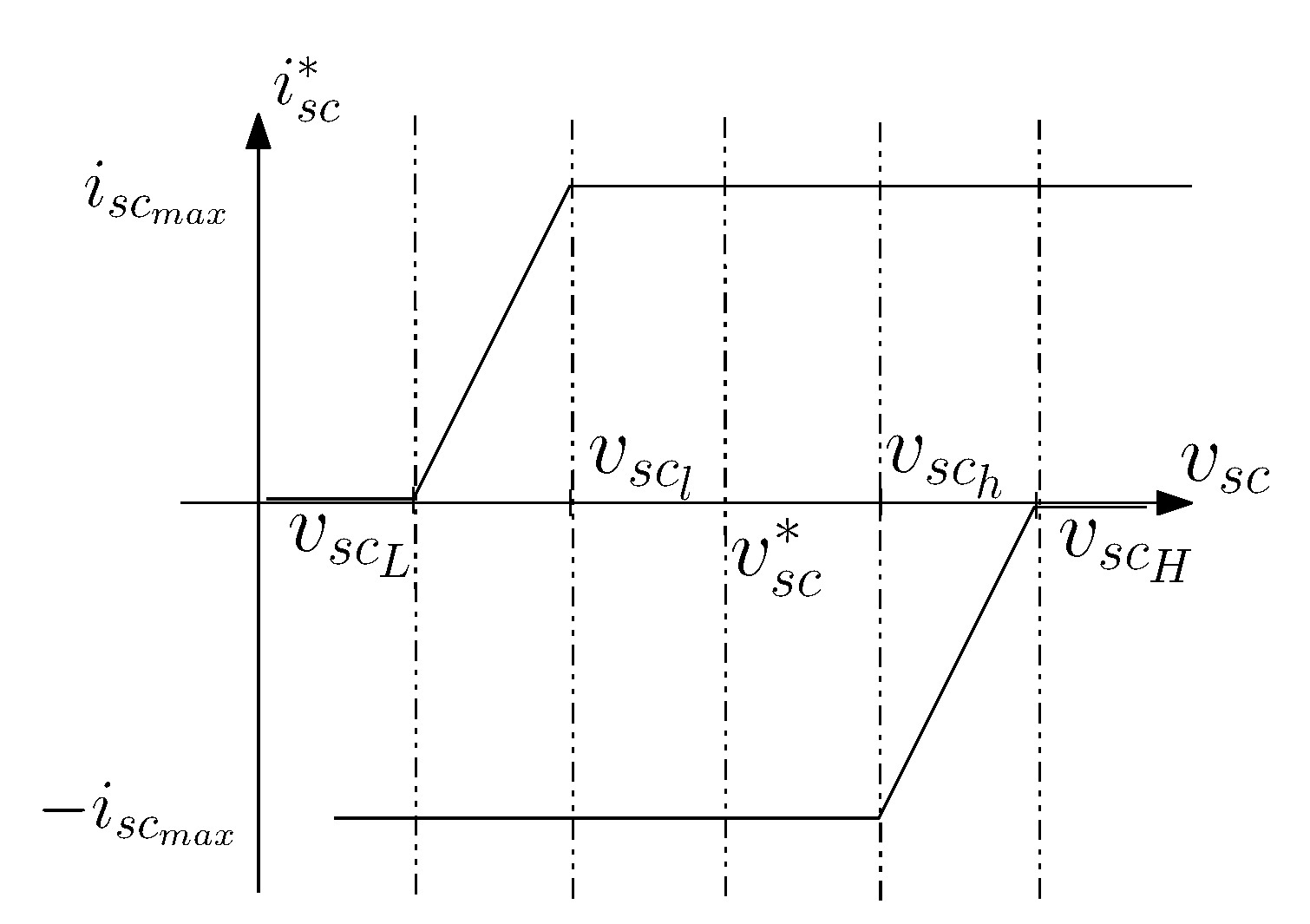
- Whenever the battery pack current remains within the allowable bounds (maximum battery current during discharge and charge ) the batteries satisfy the load power requirement and the SCs doesn’t give any assistance as shown in Figure 4. To recover the SoC of the SCs and thus the assistance, the controller maintains at a certain level the SoC when the current battery is in the allowed bounds.
It turns out that the control is based on two controllers that are selected according to the operating conditions, as shown in Figure 5:
- Controller 1 is activated when the battery current is higher than the threshold during a discharge operation or (in absolute value) during a charge operation.
- Controller 2 is activated when the battery current remains in the bounds , i.e., normal operation of the hybrid system.
We need to mention that the thresholds and can be variable, i.e., function of the allowed time of overcurrent greater than 1C (see section II) and function of the battery temperature obtained through the CAN bus.
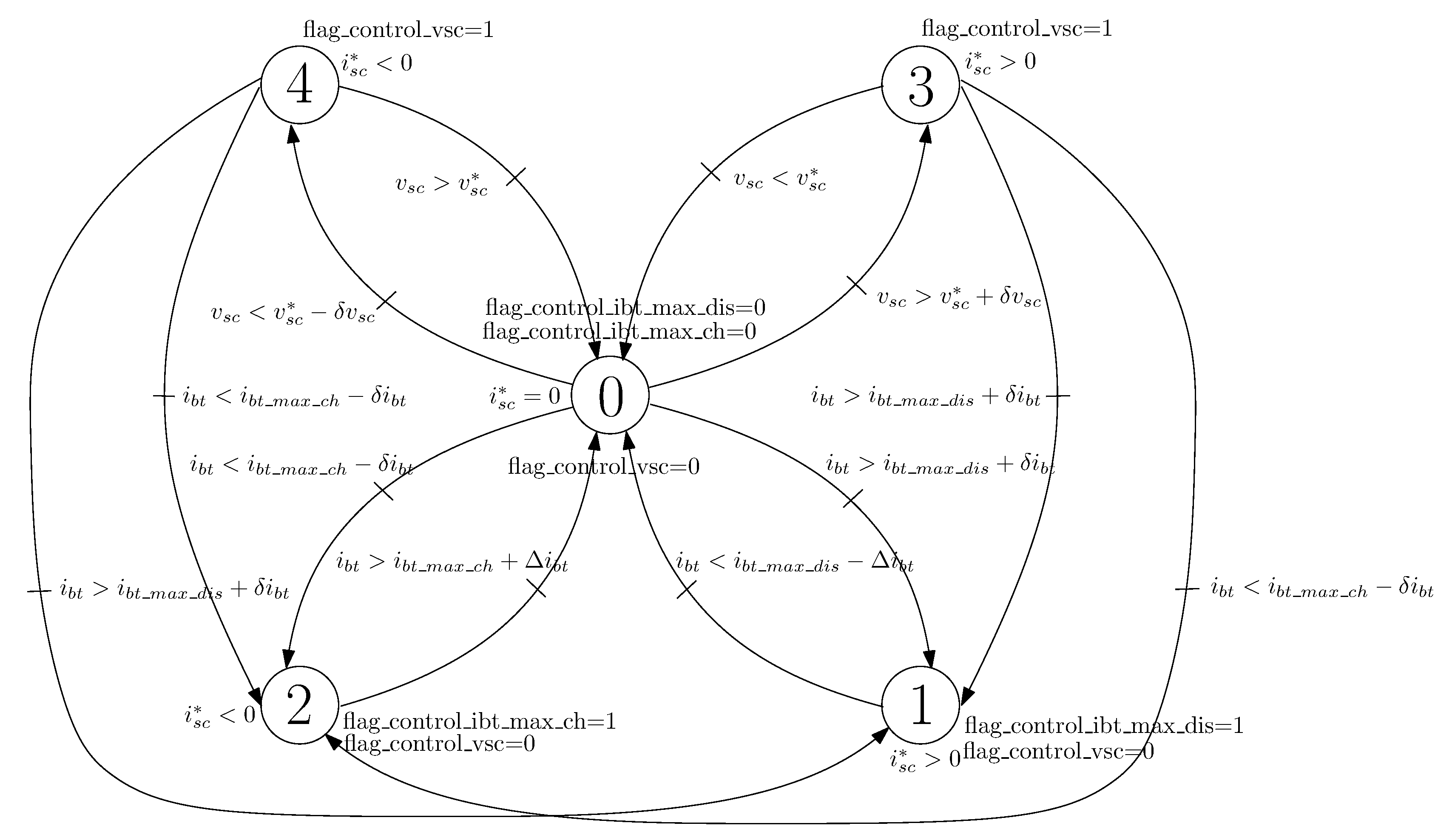
Controller 1 compute the desired current in order that the battery current does not exceed the maximum value, while controller 2 manage the SoC of the SCs. It follows that the decision block is based on the state machine as shown in Figure 6.
4.2. Design of the Controller
4.2.1. State Machine
- State 0: the battery current () doesn’t exceed the maximum value and the SCs voltage is also in the bounds , i.e., normal operation of the hybrid system. Therefore, the SCs is set equal to zero.
- State 1: the battery current () is higher than a user-defined threshold . Therefore, flag flag_control_ibt_max_dis is set to one and controller 1 is activated until the battery current is lower than .
- State 2: the battery current () is higher in absolute value than a user-defined threshold . Therefore, flag flag_control_ibt_max_ch is set to one and controller 1 is activated until the battery current is greater than .
- State 3: the battery current () doesn’t exceed the maximum value but the SCs voltage is too high. Therefore, flag flag_control_vsc is set to one and controller 2 is engaged, until the SCs voltage remains to the nominal value or the battery current () exceed the maximum values .
- State 4: the battery current () doesn’t exceed the maximum value but the SCs voltage is too low. Therefore, flag flag_control_vsc is set to one and controller 2 is engaged, until the SCs voltage remains to the nominal value or the battery current () exceed the maximum values .
It is important to mention that adequate values of the thresholds and need to be adopted to avoid chattering phenomenon.
4.2.2. Controller 1
When flags flag_control_ibt_max_dis or flag_control_ibt_max_ch are set to one, controller 1 base on a PI is engaged in order to inject or absorb the current that the battery could not inject or absorb. Figure 7 shows the sampling-time PI controller where represent the SCs current at the output of the boost converter.
So that the SCs provide current as quickly as possible, the integral action S of the PI-controller is initialized at a right value, i.e., so that is equal to or at the initialization step of the controller:
- if flag_control_ibt_max_dis is set to one, S is set to
- if flag_control_ibt_max_ch is set to one, S is set to
4.2.3. Controller 2
When flag flag_control_vsc is set to one (states 3 or 4), the SCs voltage is bring back at its nominal value :
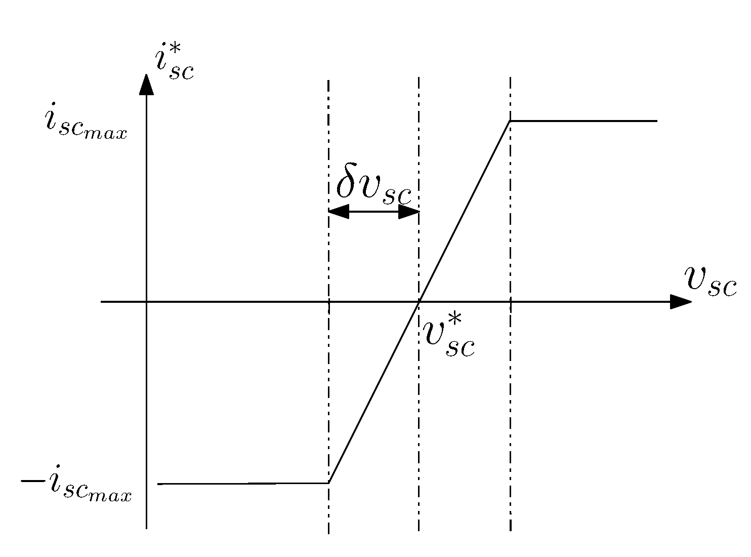
- Whenever , controller 2 computes a positive value of the SCs current as follows:so that the SCs is discharged at the maximum value as long as and later discharge the SCs by progressively reducing until reaching when . This behaviour is highlighted in the Figure 9.
- Whenever , controller 2 computes a negative value of the SCs current as follows:so that the SCs is charged at the maximum value as long as and later charge the SCs by progressively reducing until reaching when .
Controller 2 is a static controller based on Equations (1) and (2) (see also Figure 9 for a graphical representation). When the system is in state 3 or 4, the battery provides power to the load and also charge/discharge the SCs function of the state (i.e function of the SCs voltage) with the maximum allowed current of the SCs. It would have been possible to use a regular controller to compute but the static controller based on Equations (1) and (2) is interesting because it charge/discharge the SCs with the maximum allowed current of the SCs. It reduces the time needed for charging/discharging the SCs.
4.3. Experimental Results
Experiments have been conducted in the test bench where the battery current has been limited at 90 A during charge and discharge of the battery. All the controller parameters are as follows: A, A, V, V, V, V, V, V, A, and . The parameters of the PI controller have been defined empirically. It is important to mention that the response time of the PI-controller is reduced; this is achieved by initializing integral term S with an appropriate value that results in the battery current value converging fast to or .
Figure 10 shows an experimental result for a load current profile composed of 5 s at 80 A and 1 s at zero current, i.e., for operating points where the battery current remains in the bounds and the SCs voltage is in the bounds (state 0). As expected, the SCs current is null and the battery supplied all the energy to the load.
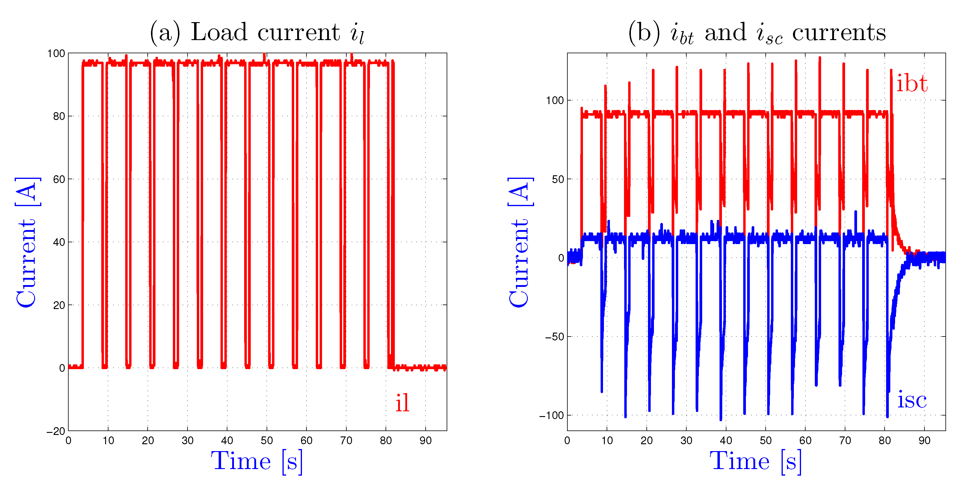
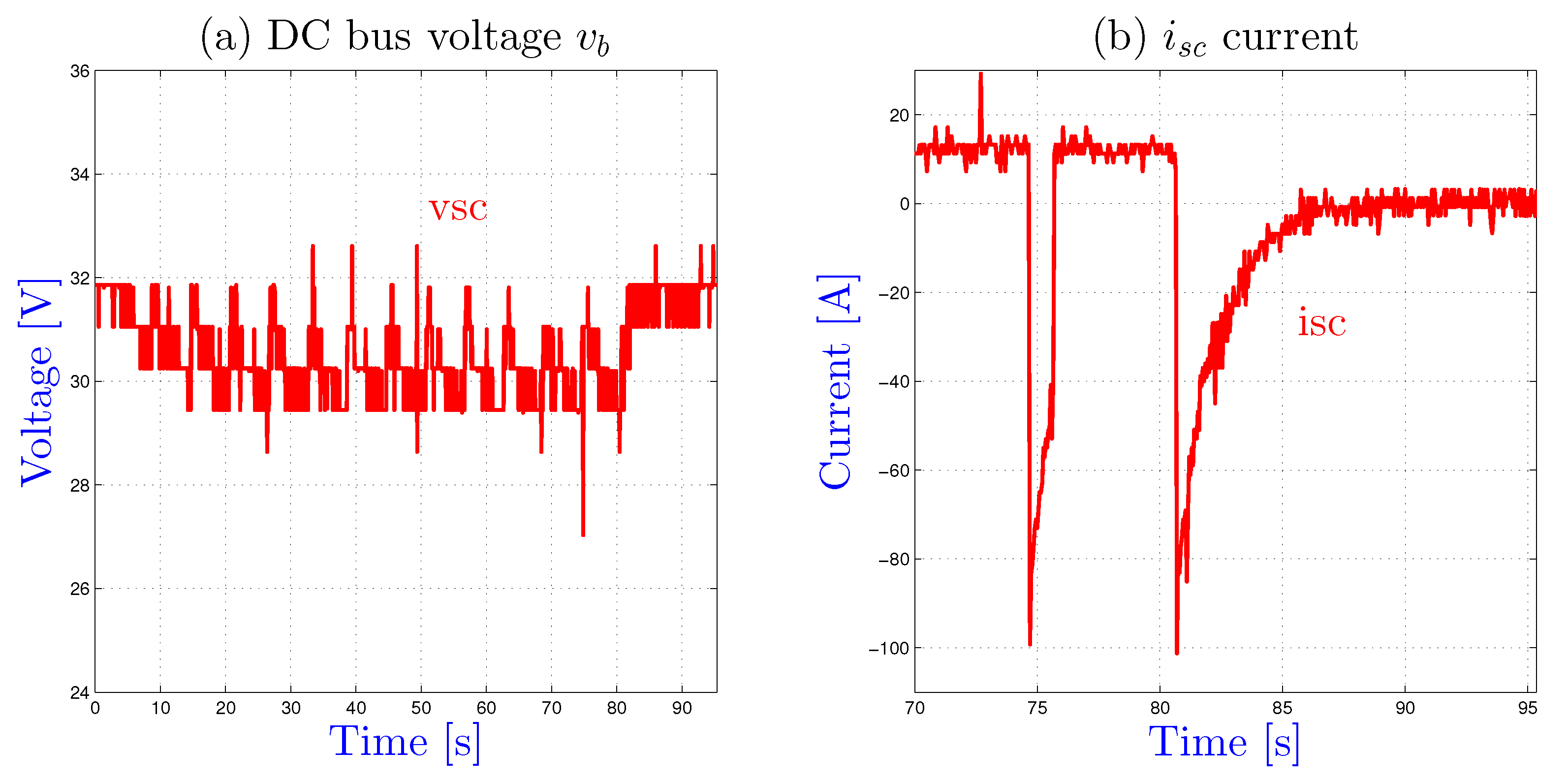
Figure 11 shows an experimental result for a load current profile composed of 5 s at 95 A and 1 s at zero current, i.e., for operating points where the battery current is greater than (state 1) and operating points where the SCs can be recharge (state 3). As expected, the SCs current provides current to the load for state equal to one. We can notice in Figure 12 that the SCs voltage is regulated at the desired value equal to 32 V and that the SCs current is always initialized at a value different from zero (see comments in section IV.B.2) to improve the convergence of to .
In fact the commutation from controller 2 to controller 1 needs an adequate re-initialization of the integral term of the PI controller and the commutation from controller 1 to controller 2 doesn’t introduce difficulty. When controller 1 is engaged, thanks to the initialization flag in Figure 7, the integral term S is initialized at or according to the system state. As noticed just above, this reduce the convergence time of to or through a fast drop of the battery current as shown in Figure 11b.
We can noticed that the results are acceptable despite the important sampling-time of the data and that the current battery remains to the limit current value or defined by the designer. We have shown that the PI controller (state 1 and 2) have been engaged so that the SCs assist the battery as long as the SoC of the SCs is not too high or low (see Figure 8). Furthermore, every time that the SCs can be charge or discharge (i.e., the battery current doesn’t exceed the allowed value), controller 2 is activated.
5. Conclusions
A single converter-based hybrid system energy management through Controller Area Network (CAN) bus communication has been studied. Experimental results show that charge-sustaining controller have low performances due to the sampling-time of the CAN bus data. Therefore, a rule-based strategy has been proposed in order to tackle with sample-time issue based on a depleting mode, where experimental results based on a 10 kW hybrid power pack coupling battery and supercapacitors prove the feasibility of the proposed approach.
As mentioned in the paper, the CAN network suffers from the low transmission rate and low quantification of data. In the current scenario, the increasing number of functionalities grows in all type of vehicles because of the decentralization of functions and leads to an over-loaded CAN network. CAN FD and FLEXRAY have emerged as new trend to comply with real-time constraints [34]. However, such adaptation does not seem the solution to control electrical systems with high performances and safety. Therefore the question of centralized/decentralized critical functions in an electrical vehicle need to be further investigated.
Author Contributions
Methodology, M.H.; software, K.S.A. and F.G. All authors have read and agreed to the published version of the manuscript.
Funding
This research was funded by the French Government Armement Procurement Agency (DGA—Direction Générale de l’Armement), in the framework of a partnership project involving E4V (Energy For Vehicle) and FEMTO-ST laboratory.
Conflicts of Interest
The authors declare no conflict of interest.
References
- Cao, J.; Emadi, A. A new battery/ultracapacitor hybrid energy storage system for electric, hybrid, and plug-in hybrid electric vehicles. IEEE Trans. Power Electron. 2012, 27, 122–132. [Google Scholar] [CrossRef]
- Ostadi, A.; Kazerani, M.; Chen, S.K. Hybrid Energy Storage System (HESS) in vehicular applications: A review on interfacing battery and ultra-capacitor units. In Proceedings of the 2013 IEEE Transportation Electrification Conference and Expo: Components, Systems, and Power Electronics—From Technology to Business and Public Policy, ITEC 2013, Detroit, MI, USA, 16–19 June 2013. [Google Scholar] [CrossRef]
- Hilairet, M.; Béthoux, O.; Ghanes, M.; Tanasa, V.; Barbot, J.P.; Normand-Cyrot, M.D. Experimental validation of a sampled-data passivity-based controller for coordination of converters in a fuel cell system. IEEE Trans. Ind. Electron. 2015, 62, 5187–5194. [Google Scholar] [CrossRef]
- Sun, L.; Feng, K.; Chapman, C.; Zhang, N. An adaptive power-split strategy for battery-supercapacitor powertrain-design, simulation, and experiment. IEEE Trans. Power Electron. 2017, 32, 9364–9375. [Google Scholar] [CrossRef]
- Castaings, A.; Lhomme, W.; Trigui, R.; Bouscayrol, A. Practical control schemes of a battery/supercapacitor system for electric vehicle. IET Electr. Syst. Transp. 2016, 6, 20–26. [Google Scholar] [CrossRef]
- Trovão, J.P.; Silva, M.A.; Dubois, M.R. Coupled energy management algorithm for MESS in urban EV. IET Electr. Syst. Transp. 2017, 7, 125–134. [Google Scholar] [CrossRef]
- Veneri, O.; Capasso, C.; Patalano, S. Experimental investigation into the effectiveness of a super-capacitor based hybrid energy storage system for urban commercial vehicles. Appl. Energy 2018, 227, 312–323. [Google Scholar] [CrossRef]
- Omran, K.C.; Mosallanejad, A. SMES/battery hybrid energy storage system based on bidirectional Z-source inverter for electric vehicles. IET Electr. Syst. Transp. 2018, 8, 215–220. [Google Scholar] [CrossRef]
- Soltani, M.; Ronsmans, J.; Kakihara, S.; Jaguemont, J.; Van den Bossche, P.; van Mierlo, J.; Omar, N. Hybrid battery/lithium-ion capacitor energy storage system for a pure electric bus for an urban transportation application. Appl. Sci. 2018, 8, 1176. [Google Scholar] [CrossRef] [Green Version]
- Deng, R.; Liu, Y.; Chen, W.; Liang, H. A Survey on Electric Buses—Energy Storage, Power Management, and Charging Scheduling. IEEE Trans. Intell. Transp. Syst. 2019, 1–14. [Google Scholar] [CrossRef]
- Khalid, M. A review on the selected applications of battery-supercapacitor hybrid energy storage systems for microgrids. Energies 2019, 12, 4559. [Google Scholar] [CrossRef] [Green Version]
- Odeim, F.; Roes, J.; Heinzel, A. Power management optimization of an experimental fuel cell/battery/supercapacitor hybrid system. Energies 2015, 8, 6302–6327. [Google Scholar] [CrossRef] [Green Version]
- Trovão, J.P.; Machado, F.; Pereirinha, P.G. Hybrid electric excursion ships power supply system based on a multiple energy storage system. IET Electr. Syst. Transp. 2016, 6, 190–201. [Google Scholar] [CrossRef]
- Bellache, K.; Camara, M.B.; Dakyo, B. Transient power control for diesel-generator assistance in electric boat applications using supercapacitors and batteries. IEEE J. Emerg. Select. Top. Power Electron. 2018, 6, 416–428. [Google Scholar] [CrossRef]
- Sandoval, C.; Alvarado, V.M.; Carmona, J.C.; Lopez Lopez, G.; Gomez-Aguilar, J.F. Energy management control strategy to improve the FC/SC dynamic behavior on hybrid electric vehicles: A frequency based distribution. Renew. Energy 2017, 105, 407–418. [Google Scholar] [CrossRef]
- Aharon, I.; Shmilovitz, D.; Kuperman, A. Multimode power processing interface for fuel cell range extender in battery powered vehicle. Appl. Energy 2017, 204, 572–581. [Google Scholar] [CrossRef]
- Mane, S.; Mejari, M.; Kazi, F.; Singh, N. Improving Lifetime of Fuel Cell in Hybrid Energy Management System by Lure-Lyapunov-Based Control Formulation. IEEE Trans. Ind. Electron. 2017, 64, 6671–6679. [Google Scholar] [CrossRef]
- Akar, F.; Tavlasoglu, Y.; Vural, B. An Energy Management Strategy for a Concept Battery/Ultracapacitor Electric Vehicle with Improved Battery Life. IEEE Trans. Transp. Electrif. 2017, 3, 191–200. [Google Scholar] [CrossRef]
- Lopez Lopez, G.; Schacht Rodriguez, R.; Alvarado, V.M.; Gomez-Aguilar, J.F.; Mota, J.E.; Sandoval, C. Hybrid PEMFC-supercapacitor system: Modeling and energy management in energetic macroscopic representation. Appl. Energy 2017, 205, 1478–1494. [Google Scholar] [CrossRef]
- Veneri, O.; Capasso, C.; Patalano, S. Experimental study on the performance of a ZEBRA battery based propulsion system for urban commercial vehicles. Appl. Energy 2017, 185, 2005–2018. [Google Scholar] [CrossRef]
- Khaligh, A.; Li, Z. Battery, ultracapacitor, fuel cell, and hybrid energy storage systems for electric, hybrid electric, fuel cell, and plug-in hybrid electric vehicles: State of the art. IEEE Trans. Veh. Technol. 2010, 59, 2806–2814. [Google Scholar] [CrossRef]
- Chung, S.; Trescases, O. Hybrid Energy Storage System with Active Power-Mix Control in a Dual-Chemistry Battery Pack for Light Electric Vehicles. IEEE Trans. Transp. Electrif. 2017, 3, 600–617. [Google Scholar] [CrossRef]
- Burke, A.; Zhao, H. Applications of Supercapacitors in Electric and Hybrid Vehicles Applications UCD-ITS-RR-15-09. In Proceedings of the 5th European Symposium on Supercapacitor and Hybrid Solutions, Brasov, Romania, 23–25 April 2015; pp. 1–20. [Google Scholar]
- Kohler, T.P.; Buecherl, D.; Herzog, H.G. Investigation of control strategies for hybrid energy storage systems in hybrid electric vehicles. In Proceedings of the 5th IEEE Vehicle Power and Propulsion Conference, VPPC’09, Dearborn, MI, USA, 7–10 September 2009; pp. 1687–1693. [Google Scholar] [CrossRef]
- Bello, L.L.; Mariani, R.; Mubeen, S.; Saponara, S. Recent Advances and Trends in On-Board Embedded and Networked Automotive Systems. IEEE Trans. Ind. Inform. 2019, 15, 1038–1051. [Google Scholar] [CrossRef]
- Li, W.; Zhu, W.; Zhu, X.; Guo, J. Two-time-scale braking controller design with sliding mode for electric vehicles over CAN. IEEE Access 2019, 7, 128086–128096. [Google Scholar] [CrossRef]
- Vdovic, H.; Babic, J.; Podobnik, V. Automotive software in connected and autonomous electric vehicles: A review. IEEE Access 2019, 7, 166365–166379. [Google Scholar] [CrossRef]
- Jiang, K.; Zhang, H.; Karimi, H.R.; Lin, J.; Song, L. Simultaneous input and state estimation for integrated motor-transmission systems in a controller area network environment via an adaptive unscented kalman filter. IEEE Trans. Syst. Man Cybern. Syst. 2020, 50, 1570–1579. [Google Scholar] [CrossRef]
- Zhang, X.M.; Han, Q.L.; Ge, X.; Ding, D.; Ding, L.; Yue, D.; Peng, C. Networked control systems: A survey of trends and techniques. IEEE/CAA J. Autom. Sin. 2020, 7, 1–17. [Google Scholar] [CrossRef]
- Xu, L.; Hua, J.; Li, X.; Li, J.; Ouyang, M. Distributed control system based on CAN bus for fuel cell/battery hybrid vehicle. In Proceedings of the IEEE International Symposium on Industrial Electronics, Seoul, Korea, 5–8 July 2009; pp. 183–188. [Google Scholar] [CrossRef]
- Li, X.; Li, M. An embedded CAN-BUS communication module for measurement and control system. In Proceedings of the 2010 International Conference on E-Product E-Service and E-Entertainment, ICEEE2010, Henan, China, 7–9 November 2010. [Google Scholar] [CrossRef]
- Li, R.; Wu, J.; Wang, H.; Li, G. Design method of CAN BUS network communication structure for electric vehicle. In Proceedings of the 2010 International Forum on Strategic Technology, IFOST 2010, Ulsan, Korea, 13–15 October 2010; pp. 326–329. [Google Scholar] [CrossRef]
- Fan, Z.; Zhang, W.; Zheng, H.; Gang, S. Distributed battery management system based on CAN field-bus. In Proceedings of the 2013 International Conference on Mechatronic Sciences, Electric Engineering and Computer, MEC 2013, Shengyang, China, 20–22 December 2013; pp. 1921–1924. [Google Scholar] [CrossRef]
- Marcon Zago, G.; Pignaton De Freitas, E. A Quantitative Performance Study on CAN and CAN FD Vehicular Networks. IEEE Trans. Ind. Electron. 2018, 65, 4413–4422. [Google Scholar] [CrossRef]
- Tiefensee, F.; Monaco, S.; Normand-Cyrot, D. IDA-PBC under sampling for port-controlled hamiltonian systems. In Proceedings of the 2010 American Control Conference, ACC 2010, Baltimore, MD, USA, 30 June–2 July 2010; pp. 1811–1816. [Google Scholar] [CrossRef]
- Monaco, S.; Normand-Cyrot, D.; Tiefensee, F. Sampled-data stabilization: A PBC approach. IEEE Trans. Autom. Control 2011, 56, 907–912. [Google Scholar] [CrossRef]
- Agbli, K.; Hilairet, M.; Bossard, O.; Gustin, F. Power Management Strategy of a Single Converter Hybrid Electrical System Based on Battery and Super Capacitors. In Proceedings of the 2015 IEEE Vehicle Power and Propulsion Conference, VPPC 2015, Montreal, QC, Canada, 19–22 October 2015. [Google Scholar] [CrossRef]
- Ma, S.; Jiang, M.; Tao, P.; Song, C.; Wu, J.; Wang, J.; Deng, T.; Shang, W. Temperature effect and thermal impact in lithium-ion batteries: A review. Prog. Nat. Sci. Mater. Int. 2018, 28, 653–666. [Google Scholar] [CrossRef]
Figure 1.
Experimental setup and regular controller of a one-converter hybrid system.

Figure 2.
Experimental results with the regular controller—nominal condition.

Figure 3.
Experimental results with the regular controller—over-battery current.

Figure 4.
Charge-depleting and Charge-sustaining modes.

Figure 5.
Controllers of the charge depleting mode with SoC recovering of the SCs.

Figure 6.
State machine of the controller.

Figure 7.
PI controller 1.

Figure 8.
Definition of the maximum SCs current () according the SCs voltage for controller 1.

Figure 9.
Definition of the SCs current according the SCs voltage for controller 2.

Figure 10.
Experimental results during nominal condition - state is equal to 0.

Figure 11.
Experimental results during nominal condition.

Figure 12.
Experimental results during nominal condition.


Table 1.
Electric characteristics of the 10 kW hybrid system.
| E4V Battery pack | |||
| 48 V | 3.84 kWh | ||
| 80 Ah | mass | 50 kg | |
| Super-capacitors | |||
| 125 V | 140 Wh | ||
| 63 F | mass | 61 kg | |
| Electric load | |||
| 80 V | 10.5 kW | ||
| 510 A | mass | 31 kg | |
| Power supply | |||
| 80 V | 10 kW | ||
| 340 A | mass | 20 kg | |
| DC-DC converter | |||
| DC bus voltage range | 0–800 V | 250 kW | |
| 300 | mass | 15 kg | |
| Switching frequency | 4–6 kHz | Operating temperature | −40…105 C |
Table 2.
CAN bus and data characteristics.
| Data | Sampling [ms] | Precision | Data Type |
|---|---|---|---|
| 54.2 | ±0.05 V | 8 bits | |
| 109 | ±0.01 V | 8 bits | |
| 109 | ±0.1 A | 8 bits | |
| 10 | ±1A | 8 bits |
Table 3.
CAN bus and data characteristics.
| Baud Rate [kps] | Data Frames on the CAN Bus | Minimum Sampling Time [Hz] | Maximum Sampling Time [Hz] |
|---|---|---|---|
| 250 | 10 | 0.5 | 10 |
© 2020 by the authors. Licensee MDPI, Basel, Switzerland. This article is an open access article distributed under the terms and conditions of the Creative Commons Attribution (CC BY) license (http://creativecommons.org/licenses/by/4.0/).
Share and Cite
MDPI and ACS Style
Agbli, K.S.; Hilairet, M.; Gustin, F. Real-Time Control Based on a CAN-Bus of Hybrid Electrical Systems. Energies 2020, 13, 4502. https://0-doi-org.brum.beds.ac.uk/10.3390/en13174502
AMA Style
Agbli KS, Hilairet M, Gustin F. Real-Time Control Based on a CAN-Bus of Hybrid Electrical Systems. Energies. 2020; 13(17):4502. https://0-doi-org.brum.beds.ac.uk/10.3390/en13174502
Chicago/Turabian StyleAgbli, Kréhi Serge, Mickaël Hilairet, and Frédéric Gustin. 2020. "Real-Time Control Based on a CAN-Bus of Hybrid Electrical Systems" Energies 13, no. 17: 4502. https://0-doi-org.brum.beds.ac.uk/10.3390/en13174502
Note that from the first issue of 2016, this journal uses article numbers instead of page numbers. See further details here.