1. Introduction
In a microgrid (MG), inverters are the interfaces between distributed energy resources (DER) and the MG bus. Depending on the control structure of the MG, its reliance on communication gains relevance. These control structures are generally classified as centralised, decentralised, and distributed. Recently, distributed strategies have become more relevant as they reduce communication requirements and mostly rely on local measurements for their operation. However, the state-of-the-art hierarchical control structure, which is a comprehensive extension of distributed control, still requires communication on the higher levels of control, and only primary controllers can be regarded as communication-free [
1].
Nowadays, most commercially available inverters lack advanced communication capabilities that enable remote control, therefore, being mainly limited to logging and diagnosis. The implementation of modern communication capabilities on the inverters is not a trivial problem, especially considering that an MG consists of distributed generation units (DGs) that might be separated by significant distances or situated in harsh and noisy environments. This communication must be reliable since it has a direct impact on the efficient coordination of the DGs or even the stability of the whole system. Moreover, the link must comply with data transmission rates and latency restrictions imposed by the process, which are generally more restrictive when approaching lower levels of the hierarchical control structure. Eventually, the architecture must be flexible enough so new DGs can be added without redefining the entire system (scalability) [
2]. Wired solutions, and in particular power line communication (PLC), have been presented as one of the best candidates for Smart-Grid (SG) applications [
3]. However, they have some limitations and deficiencies such as signal degradation due to the noise caused by adjacent electrical devices, high implementation costs, as well as the difficulty to be upgraded and scaled [
4,
5]. Utilizing wireless communication infrastructures can reduce the initial investment while increasing the flexibility and scalability of the system. Nevertheless, their reliability and coverage can be the bottleneck for their implementation in scenarios with a large number of scattered resources [
6]. Another essential factor when it comes to MG communication is not only the selection of a suitable physical-layer standard but the entire stack, including application layer protocols. Many communication stacks were developed targeting human-to-human (H2H) communication, whose requirements may differ significantly from machine-to-machine (M2M) communication. However, due to the gradual evolution of M2M communications and the new possibilities of the Internet of things (IoT) technologies, problems such as things identification, service-oriented architectures, and interoperability can also be solved [
7,
8].
With these principles in mind, this paper proposes a wireless communication infrastructure based on message queuing telemetry transport (MQTT) which is a lightweight application layer messaging protocol. This protocol is effectively capable of coping with live data streams between different levels of control of smart inverters, while also offering great flexibility. To accomplish such a design, the work will analyse the principles of MG control to define the parameters that are going to be transmitted through this specific communication framework. Subsequently, the proposed framework will be tested in the context of energy management using a laboratory testbed, which emulates a residential MG.
1.1. Review of Related Publications
In order to highlight the contributions of this paper, a critical literature review of other related works is crucial. We are aware that, other research papers targeting the integration of IoT technologies, and specifically MQTT, with MG control and management already exist. These related publications are introduced in the following paragraphs and systematically analysed in
Table 1, to summarize their strengths and shortcomings. The aim is to present how the current work can contribute to the existing literature. Regarding the main focuses of this paper which are, MG control system architecture, communication system design and modeling, integration of these two separate systems, and validating the concept by experiments,
Table 1 was structured accordingly.
In [
9], a multi-level communication platform that can be used for MG-clusters management was proposed. However, this communication system was designed to share energy-related information among neighboring MGs and it does not directly interact with a control system. In [
10], the potential of the MQTT protocol to connect home appliances and coordinate their performance was addressed. Nevertheless, the work focused more on the design approach than on the actual implementation, which is limited to a LabVIEW-based controller and a set of Arduinos. Another work [
11], proposed an MQTT-based multi-agent system to preserve electrical energy for residential DC- MGs by performing tasks such as load-shedding and load-shifting. Once again, the direct control of DERs within the MG bus was out of scope in this research, being the resources just simulated on Raspberry Pi devices.
MQTT was also proposed for smart meter data collection using a situational-awareness architecture in MGs [
12], similarly, the benefits of cloud-based servers for data logging and processing were explained in [
13]. In [
14], an energy storage system (ESS) monitoring system, based on IoT communication technologies, was proposed for a smart-MG system. The idea of internet-of-asset (IoA), which can contribute to achieving better MG control and management by introducing smart features for power devices was theoretically proposed in another study [
15]. All of these works, use IoT technologies for data gathering and monitoring, however, they do not implement any control capabilities in the system.
Regarding the monitoring aspect of MGs, a multi-layered communication infrastructure based on MODBUS TCP/IP was proposed in [
16]. This study utilized an experimental solar generation MG to demonstrate the effectiveness of their proposed architecture in terms of supporting heterogeneity and scalability. Details of the MG architecture from the control viewpoint were not included in this paper. The same shortcoming (from the authors’ point of view) was also observed in another publication [
17], although the MG control architecture was modeled in PSCAD software and experimental validations were provided. In this work, due to the lack of the design and presentation of a detailed control architecture that can fully manipulate the power-system parameters the control functionality is limited to ON/OFF operations.
In [
18], new secondary control strategies for MG control, based on the ideas of multi-agent systems (MAS) and energy internet (EI) was proposed. Although both MG control and communication aspects were addressed in this work the results were solely based on MATLAB simulations and experimental validations were not included. In addition, using web servers for communication links reduces the security measures of an MG structure. These two concerns were also spotted in the contribution of reference [
19]. In another study, an IoT-based communication system was implemented for the MG hierarchical control and islanding detection; however, same as before, realistic experimental evaluations were not provided to empower the results [
20].
Security considerations are another crucial aspect of implementing IoT-based communication systems. In [
21], MQTT messaging for DC-MG voltage monitoring was made more secure by implementing transport layer security (TLS) version 1.3. In this work, the impact of the added security measure was evaluated by calculating the increase in latency. However, the experimental testbed of this study lacks detailed MG control structures, since it was not investigated from the control engineering point of view. In another related publication, a laboratory-scale experimental communication system for DC-MGs was utilized to analyze the performance of secure and non-secure variants of different communication systems. MQTT, constrained application protocol (CoAP), and extensible messaging and presence protocol (XMPP) based systems were utilized and the latency values were compared. The results of this interesting study prove that by adding security measures the latency values significantly increase to the point that the messaging system is no longer effective for some smart applications. Nevertheless, presenting the specifics and details of MG control architecture was out of the scope of this work [
22].
Another research tackles the topic from a dissimilar point of view. Neutral current compensation (NCC) methods can contribute to preventing harmful and extensive rises of neutral current in a distribution system. Energy awareness between different units of a multi-microgrid (MMG) system improves NCC performance by using properly designed communication structures. In [
23], a two-level communication system (consisting of MODBUS-TCP/IP and MQTT) is proposed and evaluated for this application. In this study, the MMG modeling was conducted in PSCAD software and experimental validation was not included on the control side.
The related studies which are reviewed in this section are compared by their main features in
Table 1. In the last row of this table, the current work is also included and evaluated to highlight the contribution of the paper.
Table 1.
A Comparison of key features of other related research contributions.
Table 1.
A Comparison of key features of other related research contributions.
| Publication | MG Architecture (from Control Systems Viewpoint) | Communication System Modeling | Integration of Two Systems | Validation by Experiments |
|---|
| [9], 2018 | N/A | MQTT(cloud), HTTP(intermediate), MODBUS TCP/IP(local) | N/A | N/A |
| [10], 2017 | N/A | MQTT over WiFi, Broker on LabView GUI | N/A | N/A |
| [11], 2017 | N/A | MQTT over WiFi, Mosquitto Broker | N/A | N/A |
| [12], 2018 | N/A | MQTT over WiFi, LoRa, GPRS | N/A | N/A |
| [13], 2018 | N/A | MQTT over WiFi | N/A | N/A |
| [14], 2017 | N/A | Unspecified | N/A | N/A |
| [15], 2020 | N/A | Unspecified | N/A | N/A |
| [16], 2021 | N/A | MODBUS TCP/IP | Device-level | Monitoring |
| [17], 2021 | PSCAD modeling | MODBUS TCP/IP, MQTT (Thingspeak Platform) | Device-level | Monitoring |
| [18], 2021 | MATLAB/SIMULINK modeling | MQTT (Thingspeak Platform), HTTP TCP/IP | Software-level (MATLAB) | N/A |
| [19], 2021 | MATLAB/SIMULINK modeling | MQTT (Thingspeak Platform), HTTP TCP/IP | Software-level (MATLAB) | N/A |
| [20], 2021 | MATLAB/SIMULINK modeling | MQTT (Broker details unspecified) | Software-level (MATLAB) | N/A |
| [21], 2020 | Control algorithms unspecified | MQTT+TLS 1.3 (Mosquitto version 1.6.7 Broker on Raspberry Pi) | Device-level | Latency evaluation |
| [22], 2021 | Control algorithms unspecified | CoAP+DTLS, MQTT+TLS, XMPP+TLS | Device-level | Latency evaluation |
| [23], 2018 | MMG PSCAD modeling | MODBUS-TCP/IP and MQTT (Thingspeak Platform) | Software-level (MATLAB) | N/A |
| Proposed architecture | AC-MG MATLAB/SIMULINK modeling hosted by dSPACE (D1006) real-time platform, industrial grade power elements | MQTT (Mosquitto Broker) over WiFi, nodes implemented on PyCom microcontrollers, RS232 for low-level data transfer | Device-level | PCC power regulation |
1.2. Contributions of the Study
As can be understood from the literature review, and contents of
Table 1, most of the previous works mainly focus on the design and proposal of the communication system and resources coordination strategies. However, none of them addressed the problem of how to interface the communication stack with the local renewable energy source (RES)
control structures. Moreover, although some efforts were made in the use of MQTT technology for monitoring MGs parameters and assets, the possibilities of this technology for actuation purposes have not been fully exploited.
Some studies attempted to integrate communication structures into MG control strategies; however, these studies were based on software modelings which are not able to provide adequate realistic results. Furthermore, the utilized communication servers are mostly cloud-based and ready-to-use platforms which although are easy to utilize but unfortunately can be commanded without a thorough understanding of the communication protocol operational characteristics.
The few studies that offer experimental validations and results, do not present the design and implementation of MG control architecture that can be effectively integrated with the communication system. In other words, ready-to-use power devices were utilized to create the MG structure that can be regulated by user inputs, without deep knowledge about the MG control system itself.
According to the aforementioned lacks found in the literature, in this paper the authors aim to demonstrate the integration of an IoT communication infrastructure into the control scheme of smart inverters, comprehensively and in full detail. The main contributions that can empower the literature are briefly explained as follows:
The problem was initially studied from the control engineering point of view. In this sense, a grid-connected MG architecture was modeled in MATLAB/SIMULINK and uploaded on a dSPACE (DS1006) real-time platform that controlled four 2.2 kW
Danfoss inverters. Viewed in this way, the MG units (load, generation, and storage) were emulated by utilizing proper control algorithms and required industrial-grade power devices. (
Section 4.2)
From the communication viewpoint, the MQTT nodes were created on micropython enabled microcontrollers (PyCom/LoPy4) and the MQTT broker was implemented on a Raspberry-Pi device. The reason for selecting this configuration was to use low-power devices which is the essence of IoT ideology. Furthermore, no ready-to-use cloud-based server or software toolboxes were utilized for the creation of the communication system. (
Section 4.1)
In accordance with the integration of the communication system into the MG control structure, the required physical signal and data conversions were conducted in order to make the interconnection of the low-power MQTT nodes with the D1006 processor card possible. At this point, it was required to use RS232 serial ports since the DS1006 only supports low-level serial communication interfaces. (
Section 4.1)
The system performance was evaluated in different communication faulty scenarios in addition to normal operational conditions. All these fault situations were emulated by real occurrences not artificially or hypothetically created. (
Section 5)
As a result, in this study, the communication system is used as a fully bidirectional link to transmit measurements and receive reference values between the different units of the MG control structure. In other words, in our proposed system MQTT is not an additional service for data logging or monitoring but a primary component of the MG control system.
That is to say, in this paper the practicality of internal power balancing inside a grid-connected AC-MG by utilizing an easy to implement, scalable, cost-effective, and user-friendly communication system is presented. Implementation and technical details that can be useful for other researchers and developers are also provided.
To be brief, this study bridges the gap between control systems and communication engineering by tackling the aforementioned problem from both point of views which is not a trivial problem and challenging to find in the existing literature.
The remainder paper is organized as follows.
Section 2 briefly analyzes the principles of MG control. The M2M communication concept and MQTT protocol are introduced in
Section 3.
Section 4 provides a description of the proposed framework. The experimental results and analysis under normal and problematic situations such as severe communication latencies are presented in
Section 5. Finally, conclusion and future works are listed in
Section 6.
2. MG Control
By utilization of power electronics-based inverters, MGs controllability became achievable. These inverters function as the interfaces between a series of distributed resources (DRs) and sometimes ESS, and the MG bus. An MG can operate either in disconnected (islanded) mode or grid-connected mode [
24]. Generally, inverters are classified into grid-forming, grid-feeding, and grid-supporting. Grid-forming inverters, that normally work in voltage control mode (VCM), are usually attached to storage units to set the MG parameters (voltage and frequency) and sustain transitory events in islanded configuration. On the other hand, grid-feeding or grid-following inverters that work in current control mode (CCM) only measure the grid frequency using a phase-locked loop (PLL) and regulate their output. Finally, grid-supporting inverters can operate in both voltage and current control mode and contribute to the regulation of the MG [
25]. Based on their operation requirements, in some MG architectures, inverters should be able to automatically switch their mode of operation.
2.1. Hierarchical Control of MG Based on VSI Operation
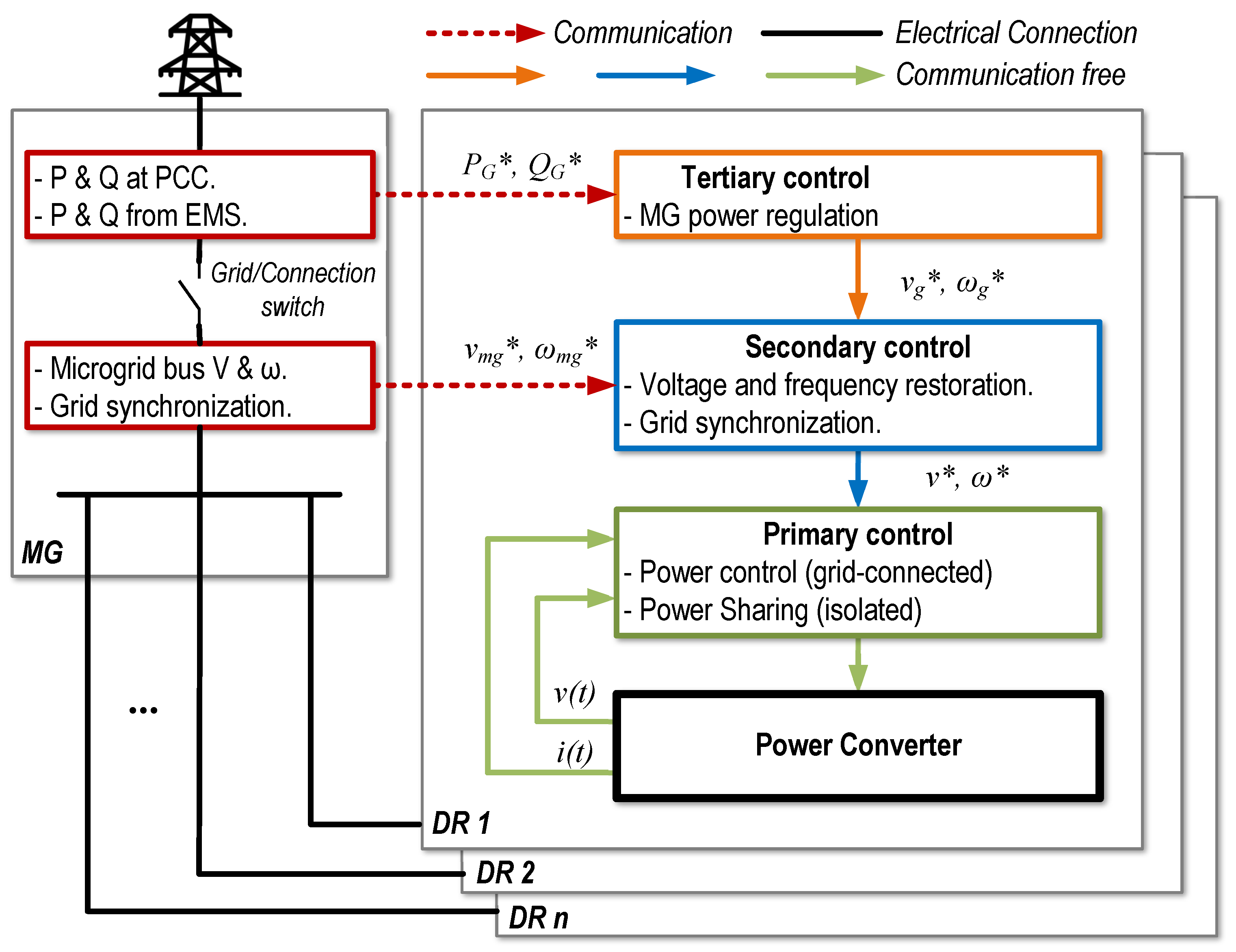
Regarding the aforementioned control structure, a conceptual schema of an AC MG control structure is illustrated in
Figure 1 [
1,
26,
27,
28,
29,
30,
31,
32]. As it can be observed, the MG consist of a series of DRs (
) connected into a common bus, forming an
, which is denoted by the solid black lines. This
can be islanded (isolated) or connected to the main grid by means of the conceptual switch
. Moreover, inside each of the DRs, a hierarchy of controllers can be seen, which depends on a series of references that can be transmitted from within the local controllers (solid arrows) or using an external communication link (dashed arrows).
According to the illustration, in the lowest level of control, the so-called inner loops can be found. In the case of voltage source grid-following inverters (VSI), they consist of an inner current loop and an outer voltage loop to guarantee the system stability. In addition, voltage and frequency droop controllers or other additional local control architectures for efficient power-sharing can be implemented. By contrast, the primary control of a current source inverter (CSI) has only a current loop, which receives references from a direct power controller or a maximum power point tracking (MPPT) system. In this case, since voltage and frequency are set by the grid, a droop controller is no longer required [
26,
32]. In case of a mode transfer, the control structure should also have the flexibility to switch from VCM to CCM softly and seamlessly. This is crucial, especially when unintentional islanding may take place [
27,
28].
Regardless of the operation mode implemented in the lowest level, it should be highlighted that from the communication point of view, the before-mentioned voltage and current loops do not require communication within the MG to operate in most of the cases. The sharing strategies, MPPT controllers, or direct power control will generate the corresponding setpoints. Nevertheless, the operation of each local control at the primary level leads to voltage and frequency deviations from their reference magnitudes in the MG. These locally generated deviations, which take relevance when operating in islanded mode or weak grids, may lead to serious issues such as inrush currents, or damages to other DGs and sensitive loads connected to the same MG. These deviations can no longer be corrected by solely relying on local measurements at inverter level. Therefore, communication with other elements of the MG is necessary. As a result, another level of control is required, denoted as secondary control. This level also takes responsibility for the synchronization and transition between islanded and grid-connected modes of the MG [
29,
33]. Finally, on the grid-connected mode, the control of active and reactive power flows at the point of common coupling (PCC) is necessary. This task is generally achieved by means of power references received from an external energy management system (EMS) or another controller that sets an optimal energy exchange with the grid. Therefore, additional communication must also be supported at this level [
1,
30,
31].
2.2. Higher-Level Control for Grid-Feeding Inverters
As mentioned in the previous subsection and illustrated in
Figure 1, the well-known hierarchical control scheme for MGs is based on the operation of voltage source grid-supporting inverters (VSIs). However, this does not cover all possible MG configurations. For example, in the experimental stage of this study that will be comprehensively explained in the following sections, the designed control structure is based on grid-feeding inverters whose operation and control methodology is relatively different. Grid-supporting VSIs aim to stabilise the grid in terms of voltage and frequency by using a secondary controller. By contrast, grid-feeding inverters are expected to be part of a stiff grid. In this case, the grid sets both frequency and voltage in the MG bus and grid-feeding inverters are not designed to intervene in this process. Subsequently, their main objective is to control the power exchange with the grid and they do not necessarily require a droop control structure [
25]. Grid-feeding inverters are mostly used for RESs such as PV panels or wind turbines. In these cases, the MPPT algorithm calculates the appropriate power setpoints. However, in certain applications such as batteries directly connected to the grid, it is also possible to set these power references based on economic considerations. In other words, in the case of grid feeding inverters the secondary control, or the MG central controller, sends the active and reactive power references to each inverter [
25]. Such a secondary (central) controller is required to be aware of the MG status. Hence, a bidirectional communication link is required.
3. Communication Structure
After presenting MG control structures and providing explanations about the fundamental differences between the various configurations in the previous section, at this point the proper IoT-based communication structure that can effectively fulfill the MG control and management requirements is introduced and described in detail.
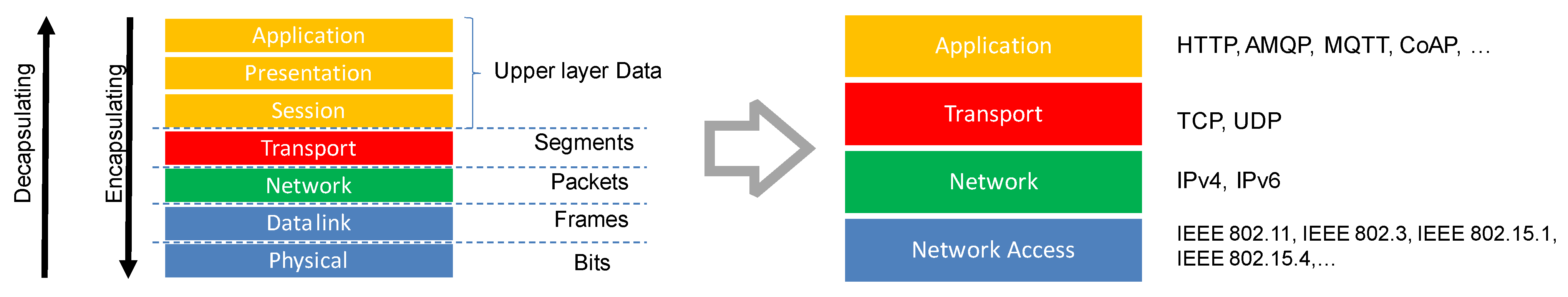
Following the open systems interconnection (OSI) model, most communication stacks are defined as a series of layers with different levels of abstraction. M2M and IoT applications have pushed the development of new protocols, which mainly reuse previous and widespread technologies such as the transmission control protocol/internet protocol (TCP/IP) in the transport and network layers while adding application layers, which are more suitable for communication between devices.
3.1. Importance of Protocol Selection in the Communication Stack
Protocol selection is the backbone of communication system design.
Figure 2 represents the idea of communication stacks proposed by the OSI model (left), as well as a simplified approach usually employed when describing IoT stacks. As can be observed, different existing protocols can be placed in each layer. In order to design a M2M communication framework for a specific application, a trade-off between multiple features must be achieved. This design concerns the four simplified layers as follows:
Network access: using a physical and data link layer communication protocol that complies with the specifications in terms of cost, range, data rate, etc.
Network: establishing adequate addressing and routing mechanisms between actors.
Transport: employing a protocol that guarantees a secure and reliable information flow between emitters and receivers.
Application: enabling the implementation of and interaction with the end user’s solutions.
Among all of these layers, the network access and application attract most of the attention during the design process as they determine the success of the solution. Moreover, the network and transport layers are usually tightly coupled with the physical layer, the application layer, or both of them.
One of the most important factors for choosing a certain physical layer protocol is, without any doubt, the physical scale of the system. However, data transfer rate, energy consumption, safety, resiliency, or costs also play a decisive role. For instance, if we are working on a home automation environment with low data transmission, the standard IEEE 802.15.4 which represents the physical layer of ZigBee can be a suitable candidate according to its low power consumption and implementation cost. By contrast, if an MG with the separation distance in terms of tens of kilometers between its different DGs or storage systems is considered, a low-power and long-range technology like LoRa can be a more successful candidate according to the required range [
34].
Regarding the selection of an application layer, the computation capabilities of processing units is the main limitation, especially for IoT devices. There are several messaging protocols available for M2M communication. Among them, we can highlight MQTT, hypertext transfer protocol (HTTP), advanced message queuing protocol (AMQP), and CoAP [
35,
36]. Each of these application layer protocols have their own benefits and drawbacks so the choice of the appropriate one depends on the application requirements and constraints [
10].
Finally, concerning the interaction with the network and transport layers, not all combinations are possible as stated above. For example, in the application layer, MQTT operates on top of TCP/IP whereas CoAP works on top of user datagram protocol (UDP/IP) which are different in nature and features. TCP is a transport layer protocol for reliable data exchange, while UDP is unreliable but provides faster transmissions. This means that reliability in CoAP communication is moved into the messaging layer to compensate for UDP reliability deficiencies [
7]. Likewise, in the network access layer, the standard IEEE 802.15.4 is usually coupled with the ZigBee protocol, which implements its own proprietary network, transport, and application layers. Nevertheless, it is also possible to link it with other specifications such as 6LoWPAN, which unlocks the potential of IP-based networks on low-power, low data transmission solutions.
3.2. MQTT Protocol
In this section the selected application layer protocol for the design of the communication system of this work is introduced. MQTT is a well-known and widely-implemented application layer protocol, operating on top of the TCP/IP stack, where the devices are normally, physically connected by means of IEEE 802.11 (WiFi) standard, however, the implementation of other physical layer protocols are also possible. Physical layer protocols details and specifications are well documented in the literature [
37,
38,
39,
40,
41,
42,
43]. MQTT is a lightweight application layer messaging protocol suitable for M2M interconnections since its packet headers are smaller in size compared to other application layer protocols such as HTTP, and CoAP [
10,
35,
36]. Furthermore, MQTT is based on a publisher/subscriber approach over different channels denoted as topics, which brings several advantages. First, the publish/subscribe system reduces the required data transmission on the digital-handshake stage. Therefore, lower latency and more simplicity are achieved. Secondly, this feature makes it possible to implement event-based solutions, saving bandwidth, and allowing for asynchronous communication. In addition, the use of topics provides a useful mechanism to encapsulate different parameters while seamlessly implementing a many-to-many communication structure. While MQTT is based on a publish/subscribe approach, CoAP (being a simplification of HTTP) follows the request/response mechanism, which means that there should always be a server listening for incoming requests. This might be a problem in some higher power-constrained applications.
It is important to point out that the implementation of MQTT (like any other protocol) is not without drawbacks. Security issues resulted from the focus on light weightiness, utilization of a central broker that disallows for global accessible networks creation and not being as popular as HTTP are the major disadvantages of MQTT. However, these downsides do not diminish the usefulness of MQTT for M2M applications due to its strong and relative characteristics.
3.3. MQTT Broker
All of the aforementioned architecture is possible since a central node denoted as the broker is utilized. The broker is responsible for the routing of messages between clients that publish and subscribe to a certain topic. This also means that publishers and subscribers are decoupled from each other by the broker, contributing to the plug-and-play features of this communication structure. Furthermore, the broker can store the messages for a certain amount of time, which allows for different levels of quality of service (QoS). A secure communication is also achieved inside the broker by executing authentication protocols among clients. One other duty of the broker is to check the status of clients by engaging with them into a keep-alive process in a defined time interval.
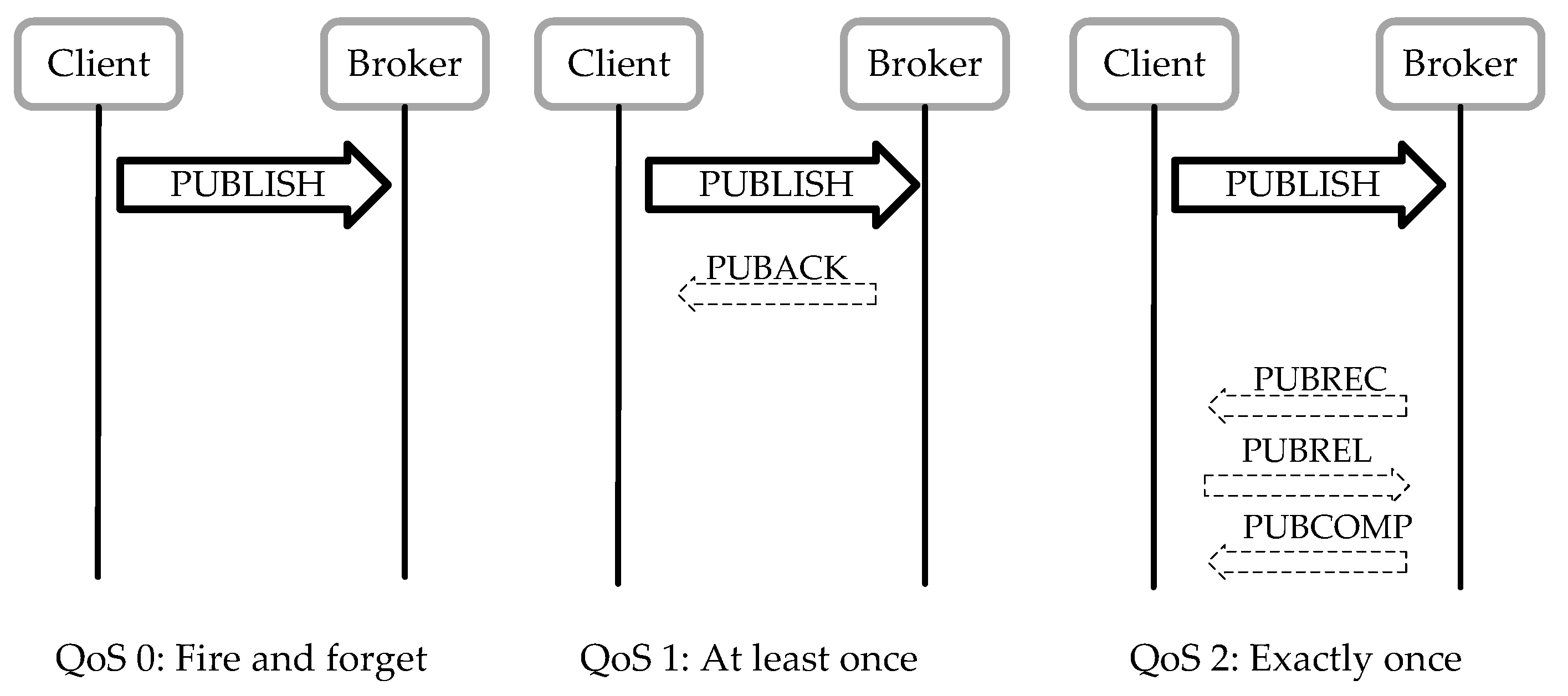
From all of the features mentioned above, the QoS is probably the most interesting one for MG applications, where error-proof information exchange is required. In particular, three QoS levels are defined within the standard. The default QoS 0 or
fire and forget means that the message is sent only once so packet losses might occur. QoS 1 implies that the message is being sent over and over again until an acknowledgment is sent by the subscriber and received by the publisher. It is also known as
at least once, meaning that duplication might occur in some cases. The highest possible level is QoS 2, or
exactly one transmission. In this case, the publisher and subscriber establish a handshake-like strategy that guarantees the correct transmission only once. The role of the broker regarding QoS levels is presented in
Figure 3.
Considering different QoS levels, a trade-off between the probabilities of losing or receiving repeated messages, versus the increase of payload complexity, must be accomplished. The sensitivity of the application to packet losses dictates which QoS should be selected [
44,
45,
46]. In addition, MQTT contain an error-handling scheme that detects any possible protocol violations and shuts down the network connection that caused the problem. This even applies to transient violations that if detected by the server, only disconnects the client from which the protocol violation originated and the connections to other clients are not affected [
47].
3.4. Security Considerations of MQTT
Following the discussion about the role of the broker in MQTT communication systems and the QoS in the previous subsection, it is crucial to discuss the security features of MQTT, which is the communication system employed in this study. Such a system can be subject to cyber-attacks or inferences of different types that may occur at different layers of the communication stack [
48]. One of the most important characteristics of MQTT is the light-weightiness of the protocol, which makes it a great candidate for IoT applications. However, this beneficial feature also means that MQTT does not contain very complicated security measures since implementing these securities result in an increase in the payload size and more messages must be exchanged for a single transmission. Some interesting studies are available in the existing literature that experimentally evaluate the detrimental effects of adding security measures to IoT-based communication system performances in terms of large latency levels. These harmful occurrences can even be so extensive that render these messaging systems unsuitable to be integrated into some levels of MG control architectures [
21,
22]. To cut a long story short, normally the MQTT security is limited to client authentication and access authorization, by default, and this is performed by the broker [
49].
In the proposed system of this paper, we used Eclipse Mosquitto, which is a well-known and open-source MQTT broker [
50]. Mosquitto provides users with various options for the level of security. At the most basic level, the operation is totally unsecured without any authorisation, authentication, or encryption mechanism. This means any client with access to the network can connect to the broker by knowing the IP address of the broker. Moreover, once connected, the client can subscribe to any topic and also publish on all topics. Authentication can be achieved by requiring a username and a password from the clients at the most basic level. However, if no additional security measures are adopted, these elements, as well as the payload, are transmitted in plain text on the MQTT request. A simple way of solving this is by using transport layer security (TLS) and secured sockets layer (SSL). This mechanism also offers the possibility of using the client certificate information for authentication and authorisation purposes. In addition to that, if even more security is necessary, there is always the possibility of encrypting the payloads. As far as the authorisation is a concern, the subscription to and/or publication in a topic can be restricted based on the authentication information or even the QoS at which the client is operating. Nevertheless, a higher level of security also translates into larger latencies, as well as higher computational requirements on the client nodes [
46].
It is useful to noted that the physical and medium access control (MAC) layers can be also subject to different types of attacks such as jamming and eavesdropping. Several techniques have been implemented to reduce the possibility of these types of attacks such as transmitting in lower power or using more complicated modulation techniques such as frequency hopping spread spectrum (FHSS) and direct sequence spread spectrum (DSSS) in order to make the signal detection more difficult for the attackers to acquire and subsequently manipulate [
51].
For the sake of clarity, it should be mentioned that in this study security discussions are limited to the information provided in the current subsection. The contributions of the paper that are highlighted in
Section 1.2 denote that deep analysis of security aspects is out of the scope of this work. Further details on these subjects are well-documented and can be found in the existing literature [
21,
22,
49,
51].
4. System Description
So far the aspects of MG control and M2M communication systems that are related to this study have been introduced. In addition, MQTT which is the chosen communication protocol for this application has been comprehensively introduced. In this section, a detailed description of the proposed system is provided.
To make a long story short, this study aims to propose and analyse a wireless communication architecture that fulfills the information exchange requirements of MG control and management. In this way, first, a communication interface that aligns with the conventional control architecture of each inverter was implemented. Subsequently, a compatible MG model was developed for testing purposes.
4.1. Communication Interface with Inverters
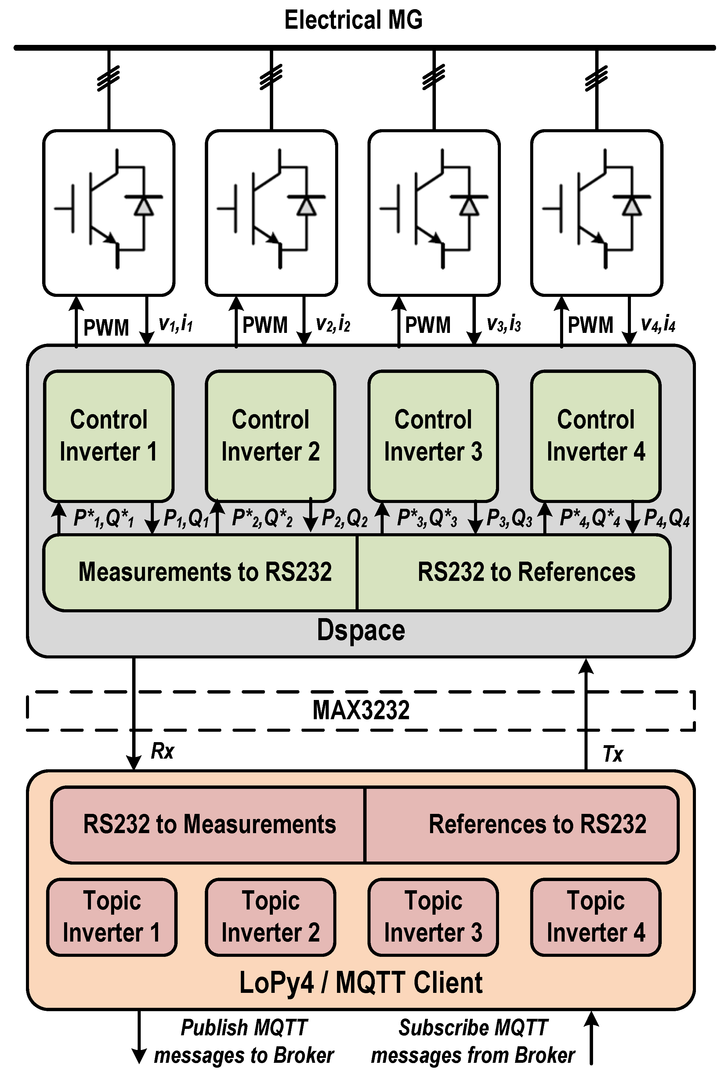
As the first step of system description, the communication system proposed on the inverter side is illustrated in
Figure 4. As it can be observed, the system was able to control the four inverters available in the setup. Nevertheless, the proposed structure can be scaled up to any number of DGs since the MQTT protocol only limits the topic length and payload size, but not the number of publisher/subscribers. The inverters were controlled by a dSPACE (DS1006) real-time platform (grey block) which generated the PWM signals based on local voltage (
) and current (
) measurements and the individual controllers. For simplicity, the controllers were implemented in the same receiver/transmitter (RT) platform. Nevertheless, no parameters were exchanged locally, so in practice, they can be considered as independent systems.
On the other hand, the MQTT client (orange block) was implemented in a microcontroller system based on the ESP32. This system subscribed to the corresponding references that were generated for each inverter by an external system. It was also responsible for publishing the measurements from each local controller. As in the case of the dSPACE, the same microcontroller subscribed and published in 4 different topics, one per inverter. However, a single-microcontroller, single-topic configuration could have been followed as well.
Finally, in order to communicate both systems, a protocol conversion was needed. The dSPACE platform, as it is also the case of most discrete DSP systems used commercially, only allowed for low-level communication by RS232 serial ports. To integrate the dSPACE platform with the microcontroller, an adapter (MAX3232) was used to transform the 3.3 V logical levels of the UART communication in the microcontroller, to the RS232 levels.
In addition to the physical signals conversion, the data representation was also adapted into an array of bytes in order to be transmitted over the serial communication. This representation included not only references or measured values but their interpretation. Moreover, as a single system was hosting four inverters, an addressing mechanism was implemented as well. The conversion was carried out by functional code blocks, which encoded and decoded the references and measurements into an adequate byte-based representation.
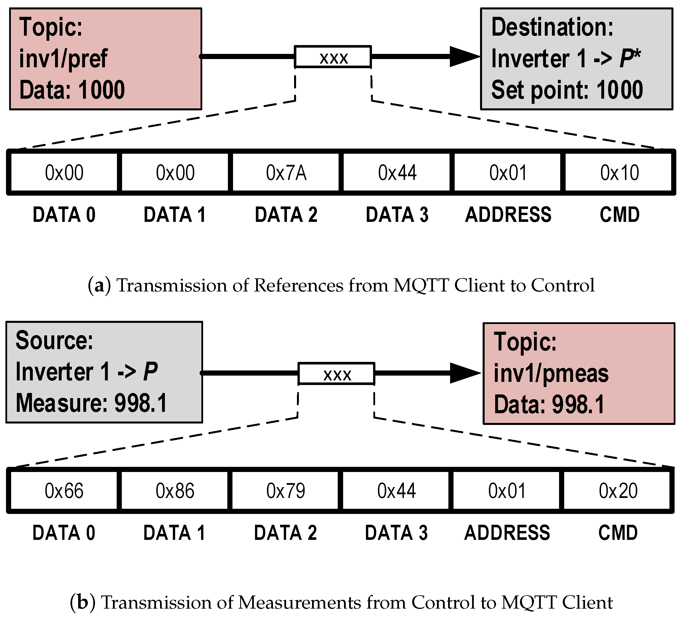
Figure 5a shows how a setpoint received in the MQTT Client was encoded to be transmitted to the dSPACE. In
Figure 5b, the opposite process is shown, where a measurement from the dSPACE was encoded and sent to the MQTT client for its transmission.
The structure of the byte array streamed between the devices was similar in both scenarios. First, the reference parameter or measurement was converted from its 32-bits float representation into 4 bytes (DATA 0–3). These bytes were subsequently sent following a little-endian ordering. Two additional parameters were also added: an address (ADDRESS), which determined the inverter; and a command byte (CMD) which indicated the interpretation of the value.
4.2. MG Architecture
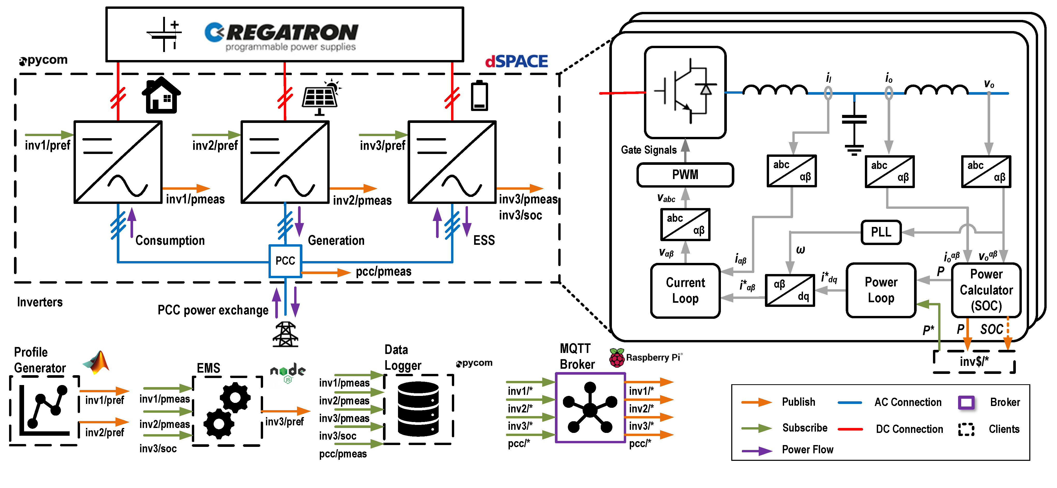
Over the implementation of the previously described communication architecture, an MG structure was created. Its components are described in the following subsections and illustrated in
Figure 6.
4.2.1. Inverters, Proposed Topology for an AC MG
The first dashed block named
Inverters in
Figure 6, represents the whole MG control structure consisting of three grid-feeding inverters operating in grid-connected mode. These inverters were controlled through a dSPACE unit that provided a platform to implement the control structures coded in Matlab/Simulink. In this proposed topology, each of the inverters was used to emulate common resources of an AC residential MG.
Inverter 1: Simulated the electricity demand in terms of household consumption. It was emulated by sending a set of power references to the inverter using the MQTT communication system. These power references were obtained by using a stochastic model with 1-min resolution data for 24 h [
52].
Inverter 2: Emulated the PV generation considering directly the output of the DC/AC inverter. The methodology was the same as inverter 1, creating the solar generation profile by the received power references. These references were generated by using real solar patterns gathered for three years in Cordova, Spain [
52].
Inverter 3: Implemented an ESS model, which is the only controllable element in the system. The system received the power references from the EMS, which periodically calculated them based on the state of charge (SoC) of the ESS and the real power measurements of inverters 1 and 2. This determined the surplus or lack of energy that the ESS might provide if its SoC is enough [
52].
PCC: In addition, not only the real measures of the output power in each inverter were available in the MQTT architecture, but the power flow at the point of common coupling (PCC) was also acquired and transmitted.
4.2.2. Control Algorithm for Grid-Feeding Inverters
A detailed view of the main blocks of the control system employed for each of the grid-feeding inverters is shown on the right side of
Figure 6. In this schema, both the local variables (grey lines), as well as the published (orange) and subscribed (green) parameters are shown together with the control structure.
As can be observed, the system was composed of two main control loops in series. First, the control calculated the instantaneous power (
) using the alpha-beta transformation of the three-phase output currents (
) and voltages (
). At this stage, the power was published in the corresponding channel of the inverter in the MQTT architecture. Moreover, in the case of the ESS, the state of charge (SoC) was estimated and sent as well. Subsequently, the calculated power (
) was compared with the power reference received on the MQTT topic for each inverter. Then, the error signal was fed to the PI power controller which generated the corresponding current to achieve such power. Since only active power was being controlled in this particular case, the output current corresponds with the d component of the synchronous reference frame (dq0). This reference frame was obtained by a synchronous reference frame—phase-locked loop (SRF-PLL) linked to the output voltage (
) imposed by the grid connection [
53]. Afterward, and by using the obtained angular frequency (
) the alpha-beta current reference was transposed to the synchronous reference frame. At this stage, the reference current (
) and the output current of the inverter (
) were fed to the current loop, which based on the error signal for each component (
) regulated the output references given to the PWM generation (
) and, therefore, the gate signals. This control stage was composed of a series of proportional resonant (PR) controllers that selectively compensate the fundamental frequency and the harmonics 5th, 7th, and 11th.
4.2.3. Profile Generator
The load/generation profile generator is an independent MQTT client in the proposed architecture. This client publishes the power references for inverters 1 and 2. It was programmed using the Matlab language and enabled us to seamlessly create the profiles of household consumption and PV production. However, it must be noticed here that in a residential MG, these profiles are imposed by the users, external climate conditions, and other factors. Moreover, it must be highlighted that this client does not exchange any information with other elements and its sole purpose was setting the power references for the simulation of realistic generation and consumption profiles.
4.2.4. EMS
As a well-known fact, it could be stated that the EMS is the cornerstone of MG management as it determines the optimal power operation of the ESS to minimise exchanges with the main grid. These power exchange minimisations contribute to economic considerations improvements and also provide some other important benefits such as avoiding harmful overvoltage occurrences in low-voltage grids, power-lines usage optimisation due to internal energy balancing and improvements in grid power quality and stability by avoiding undesired fluctuations.
Additional details and description of the configuration of the EMS can be found in a previous work [
52]. As can be observed in
Figure 6 the MQTT client created for the EMS subscribed to three topics: (i) power measurements from inverter 1, (ii) power measurement of inverter 2, and (iii) SOC of the ESS simulated by inverter 3.
Once those values were received by the EMS, the next step was to calculate the difference between PV generation and household consumption. If this value was positive, the EMS would attempt to charge the ESS by publishing negative power references for inverter three. By contrast, if the aforementioned value was negative, the EMS published positive power references for inverter three, which discharged the ESS model implemented in the inverter control structure. The charge or discharge procedure would be carried out providing the ESS was able to handle selected power, which was determined by the SOC and the estimated evolution. If the ESS was full, the excess power should be injected into the grid. On the other hand, when the combination of ESS and PV was not enough, the deficit was imported from the grid. The EMS is coded as a Node.js application.
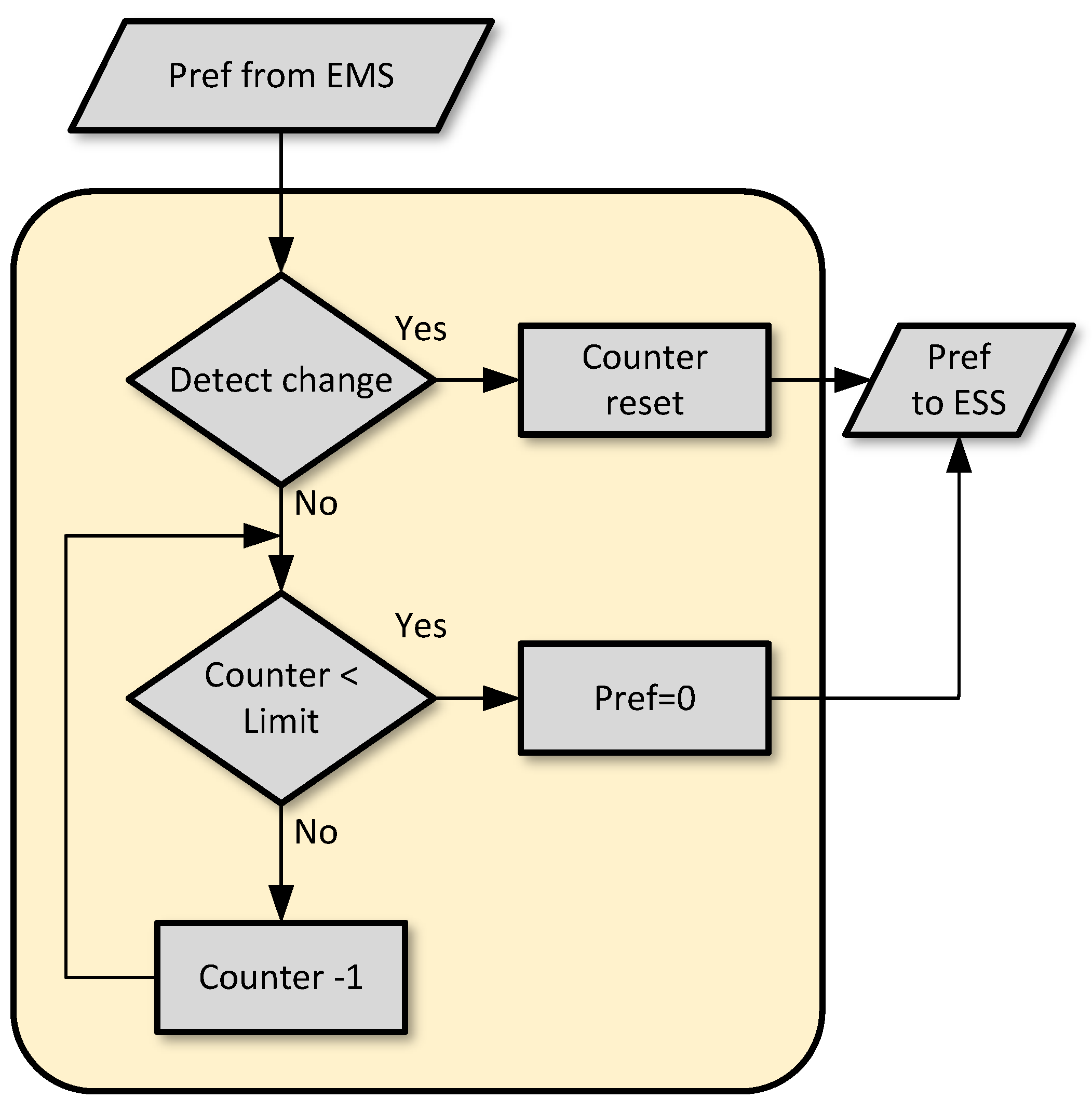
4.2.5. ESS Safety System
In case of an unstable communication system or a total failure, a safety measure is required for the ESS to prevent damages that may occur by faulty operations. This ESS safety system, which is included in the local control system, checks if a new reference is received in a certain amount of time or timeout. If no new setpoint is received for the given time threshold, a predetermined reference is set until the communication is recovered. For the experiment, the safety power reference was set to zero, which practically means shutting down the ESS in order to avoid a false and harmful operation.
Figure 7 illustrates the ESS safety system flowchart.
4.2.6. Data Logger
To illustrate the potential of the MQTT protocol, a data logger was implemented using another LoPy4 platform. This client subscribed to all of the measurements published by the inverters, as well as the SOC of the ESS. Subsequently, the values were recorded in a comma-separated values (CSV) file inside the flash memory of the device for post-processing.
4.2.7. MQTT Broker
As explained in
Section 3, the MQTT framework consisted of several clients and a broker that operated as the communication server. In this case, the broker was implemented on a Raspberry Pi device using Eclipse Mosquitto [
50].
5. Experimental Results
Following a comprehensive system description in the previous section and explaining its key elements, a series of experimental tests have been performed to validate the proposed infrastructure and evaluate the system performance under normal and faulty situations. In these set of tests, the performance metrics are:
The electrical energy exchange values and characteristics of the MG with the stuff-grid at the PCC in different scenarios.
The ESS charge and discharge pattern differences due to the operational status of the communication link.
The description of the tests, accompanied by their results and analysis, are presented in the following sections.
5.1. Experimental Setup
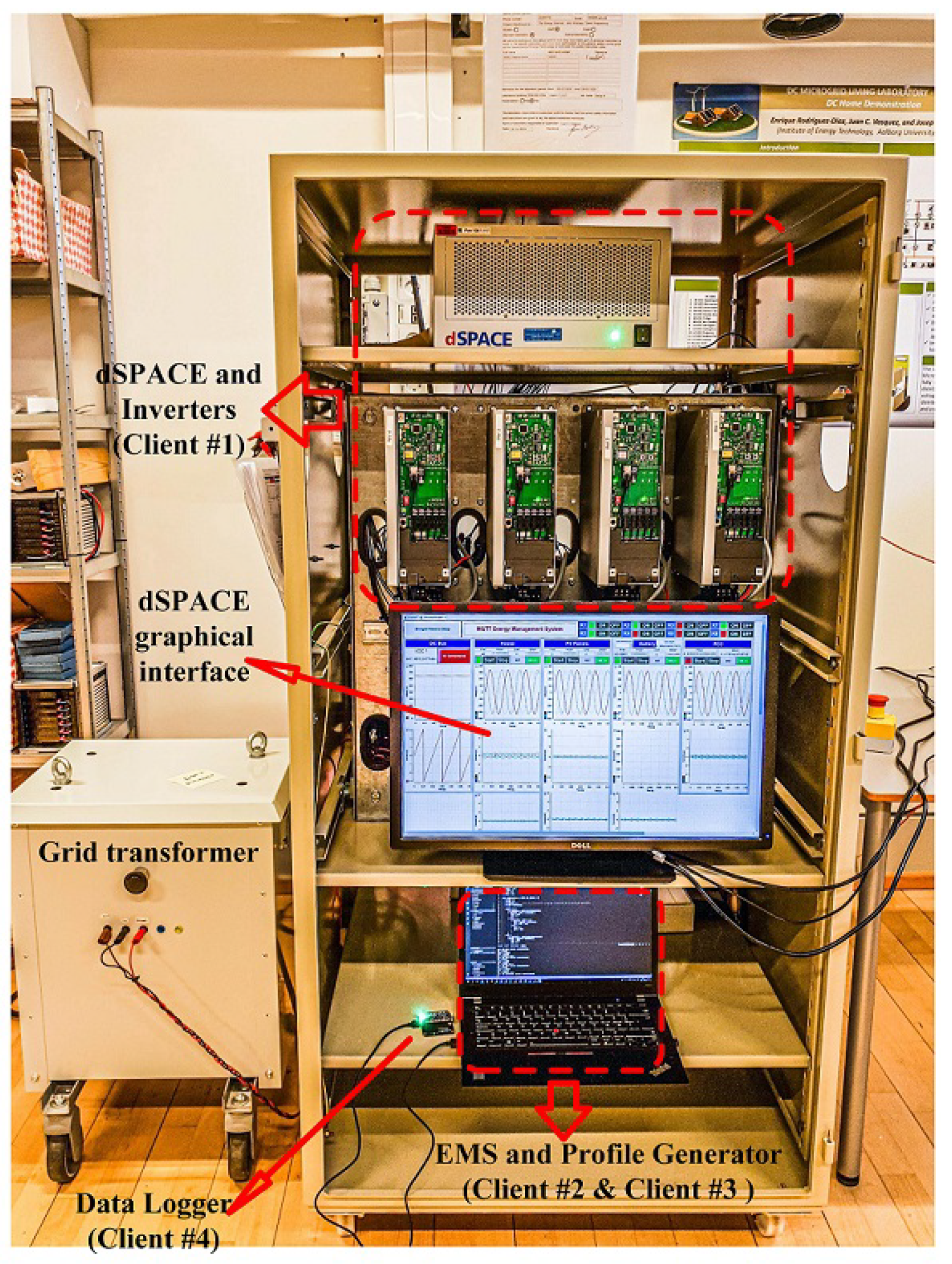
The experimental testbed, based on the proposed system described before, is illustrated in
Figure 8, where each component is specified and highlighted. This setup contains electrical and communication sections that are presented in detail.
In the electrical part, each inverter is connected on the DC side to a bi-directional DC power supply (REGATRON) with a nominal voltage of 650 V. On the AC output of each inverter, an LCL filter is used, which is then connected to a grid transformer after passing through a PCC.
The communication architecture is composed of four MQTT clients. Client #1 is the dSPACE + LoPy4 module, which connects to the inverters for their control. Clients #2 and #3 are the power profile generator and the EMS respectively. Both clients are software-based, and both run on a laptop system connected to the local wireless local area network (WLAN) using WiFi. Finally, client #4 is the data logger, which is also connected to the WLAN and to the laptop for powering purposes. It implements an embedded file transfer protocol (FTP) server, which provides access to the comma separated values (CSV) files recorded in its flash memory. In addition, the wave-forms of the inverters are monitored using the dSPACE graphical interface Control Desk. This application runs on another desktop PC connected to the dSPACE using fiber optic communication link. Although Control Desk provides the capability of controlling the inverters, in this case, its only purpose is to receive the stream of real-time measurement and represent them so the adequate operation of the system can be monitored.
5.2. Latency Analysis
In line with presenting experimental results, the first element tested is the latency of the MQTT communication structure. Generally, in MG control, communication is mostly used for the higher levels, where the message intervals are in the range of milliseconds or seconds for the secondary control, up to minutes, hours, or even more for strategic planning and energy management level [
54].
5.2.1. MQTT Latencies for Different QoS Levels
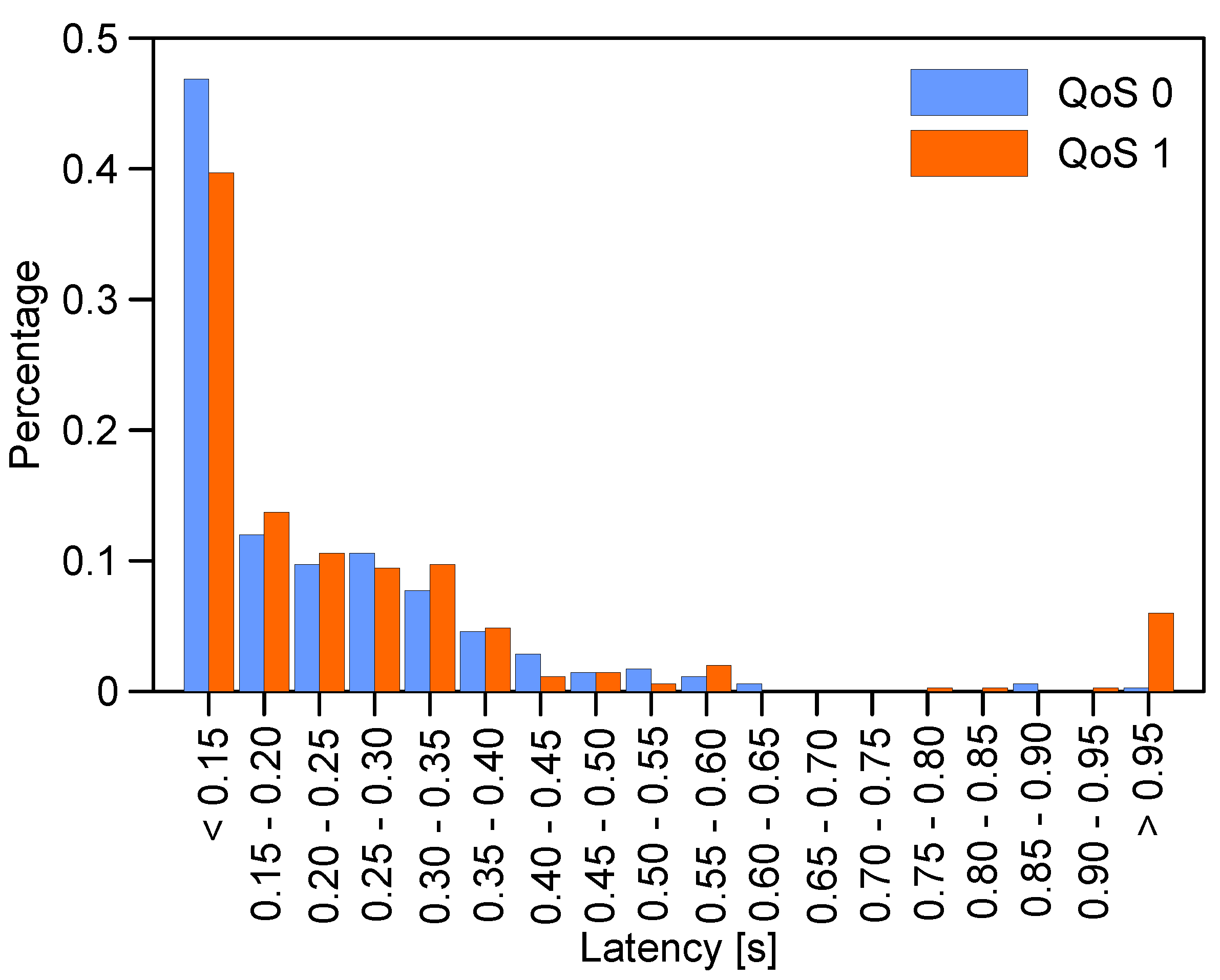
In this work, the latency is measured by creating a timestamp for each published message and subsequently comparing it with the timestamp created for the same message on the subscriber side at the reception. Since two independent (PyCom/LoPy4) microcontrollers are employed, their real-time clocks (RTC) are synchronised using a common network time protocol (NTP) server. The collected data, consisting of both timestamps (sender and receiver), is recorded for post-processing as a CSV file on the receiver unit. The latency results are illustrated in
Figure 9 where the percentage of received MQTT messages for a given time range is represented, showing both QoS 0 (blue) and QoS 1 (orange). QoS 2 was not included since this level considerably increases the number of transmissions required for a single message. Because of that, QoS 2 is mostly used for very sensitive applications such as banking transactions in order to avoid message duplication. For IoT applications, which by nature consist of low-power devices with low processing capabilities, QoS 2 makes very little sense. Therefore, it is not even implemented in some of the most common frameworks for MQTT protocol.
The total number of samples in this test is 350 messages, transmitted every five seconds. Comparing the results for the two different QoS, a substantial difference is observed for delays over one second using QoS 1 that never happens in the case of QoS 0. A complete analysis of the communication system would be necessary to identify and characterise the cause of this delay, which falls out of the scope of this work. Nevertheless, considering the features of each QoS level, the “at least one” policy of QoS 1 makes it more likely to incur larger delays (messages are resent if no acknowledgment is received) than the “fire and forget” strategy of QoS 0. Another finding from comparing these two QoS levels is the fact that considerably more messages are delivered within less than 150 milliseconds for QoS 0. This shows the behavior of each QoS.
As a general statement, in the case of QoS 0, the latency is relatively low in every transmission, but there is no guarantee that all packets sent by the emitter are received and tagged with a timestamp by the receiver. On the other hand, QoS 1 shows a higher latency, which is a consequence of the re-transmission of the messages until an acknowledgment has been received. It is useful to note that, at the end of the experiment, the expected count of 350 messages was captured on the receiver side, so no package lost statistics are possible.
5.2.2. Latency Comparison of MQTT and LoRaWAN
In order to prove the effectiveness of the proposed MQTT system in terms of acceptable latency values, the aforementioned sets of results are compared with another well-established communication system. LoRaWAN MAC protocol that works on top of a proprietary physical layer technology called LoRa represents a low-power wide-area network (LPWAN) communication architecture that is suitable for IoT applications. Its technical specifications and characteristics are well documented in the literature and providing further descriptions here are not necessary [
55,
56].
The same test configurations, as described before for the MQTT system, were used to measure the latency values of LoRaWAN and the results are compared with the previously measured MQTT latencies in
Table 2. It is important to mention that LoRaWAN supports six levels of spreading factors (SF) ranging from 7 to 12. The idea of SFs is to sacrifice coverage for throughput and vice versa [
55,
56]. However, in this test, only three SFs (10,11,12) are included since the lower SFs (7,8,9) are proved to be not reliant enough to be compared with very robust MQTT-TCP/IP-WiFi combination even for very short-range applications.
As it can be observed from the results of
Table 2, the average latency values of the MQTT system are always lower than the different LoRaWAN variants even in the case of QoS 1 which includes re-transmissions for delivery acknowledgments. In fact, they are much lower compared to the highest LoRaWAN SFs (11 & 12) that provide wider coverage comparing to IEEE 802.11 (WiFi) or other short-range wireless protocols [
57]. However, for the application of our interest long-range capabilities are not required.
5.2.3. Final Latency Remarks
It is important to state that, the latencies analysed in this section are overall or end-to-end latencies of the MQTT communication system. These latencies contain several independent elements which are queuing latencies, processing latencies, MAC latencies, and finally transmission latencies, which each of them can contribute to differences in end-to-end latency values. For example, IEEE 802.11 (MAC) protocol, which is the base of the experimental testbed in this work, is able to support both synchronous and asynchronous data transfer. IEEE 802.11 (MAC) operates in asynchronous mode by default while utilizing carrier sensing multiple access with collision avoidance (CSMA/CA) scheme. However, it can also accommodate connection-free protocols such as time division multiple access (TDMA). The MAC latencies can considerably change the end-to-end latency values since their magnitude can be quite different between connection-based and connection-free protocols. With these details in mind, it is important to state that we are only interested in the end-to-end latency values since their magnitudes can affect the control system behavior [
58,
59].
Finalizing the latency discussions, it is crucial to mention that a communication system with latencies is the scale of the measured values of this test is not fast enough to be utilized for very rapid power-management processes, such as MG bus voltage and frequency regulations by secondary controllers. Nevertheless, for the application of this study, that is transmitting power references for grid-feeding inverters and subsequently regulating the power flow at the PCC the latency level is acceptable since it is an energy-management level procedure. In other words, the application of interest falls in the category of tertiary level that is the slowest among other levels of MG control architecture where transmission intervals are normally in the scale of minutes if not more [
1,
54].
5.3. Integration of Communication in the Control Structure
After presenting latency analysis, in this subsection, the integration of the proposed communication structure with the control system is validated. In this sense, a series of power references are generated and transmitted and the response of the system is monitored. For this aim, only one of the inverters connected to the dSPACE + LoPy4 client system is sufficient. In addition, an embedded microcontroller is used for generating a profile and monitoring the response. The microcontroller client generates a series of random active power references with a fixed interval of two minutes between them. Each of these references is recorded in a CSV file inside the microcontroller together with a timestamp for post-analysis.
The references are sent to inverter one by using the topic “
inv1/pref”. The client connected to the dSPACE is subscribed to this topic and receives the power reference changes. These references, following the architecture proposed in
Figure 6, are integrated into the control loop of the inverters. Since all inverters are working on grid-feeding mode, a change in the power reference results in a change in the active power measurement at their output. This output power is calculated and published on the topic “
inv1/pmeas” with a fixed five-second interval. Nevertheless, the flexibility of this communication allows for setting asynchronous transmission based on changes in the values. Finally, the transmitted power measurements are received in the same microcontroller that generates the power references, which is subscribing to the inverter one power topic, “
inv1/pmeas”. Afterward, a timestamp is added to each measure, which is recorded into another CSV file for post-analysis.
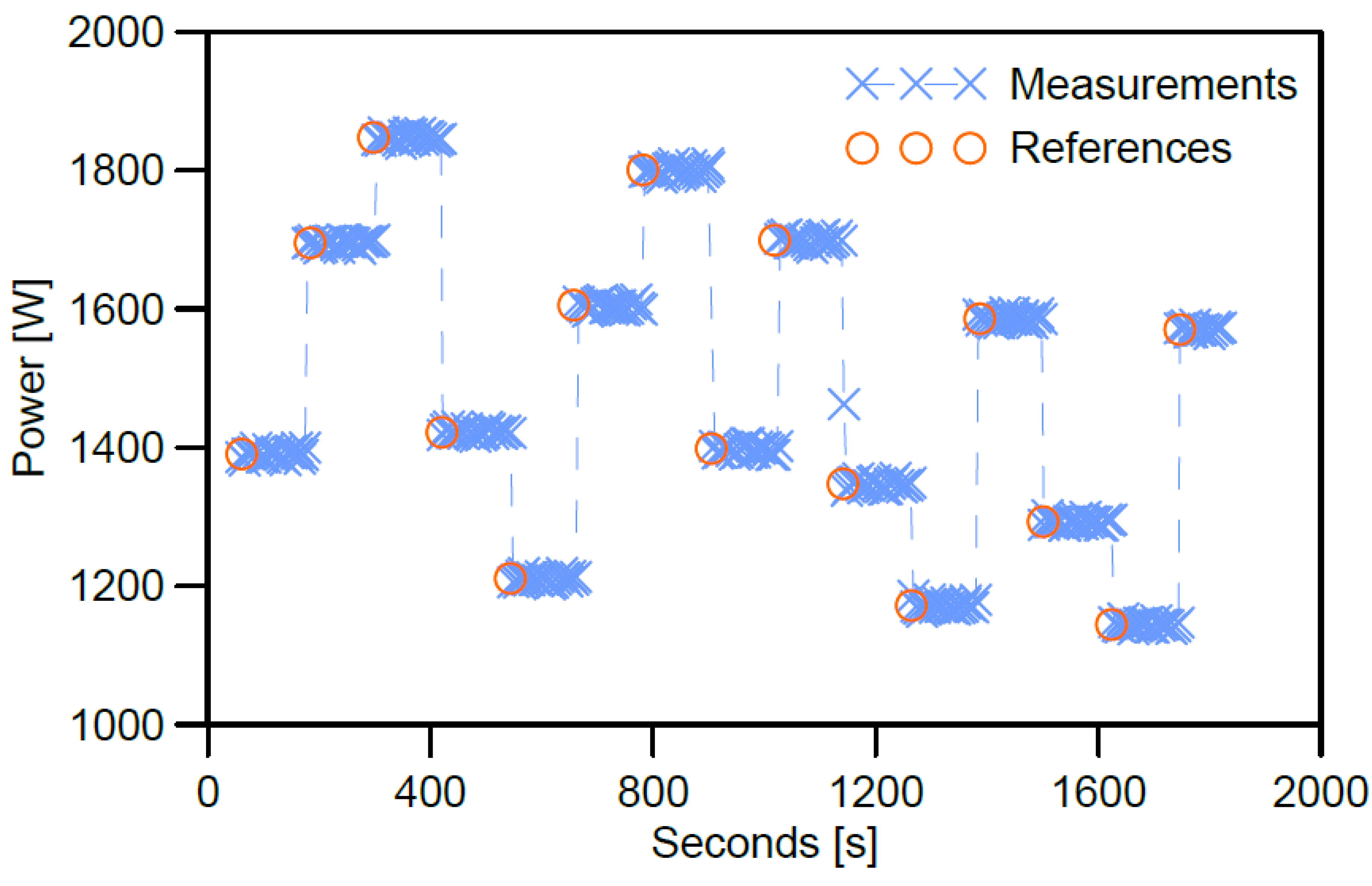
Figure 10 illustrates the results of this test for a running time of half an hour. In the period of the experiment, fifteen power references are transmitted.
The published power references are indicated by orange circles while the blue markers display the power measurements of the inverter. As can be seen, the measured power (blue) always matches the power trajectory of the references (orange) set remotely. The same graph also demonstrates the total logical separation between the reference sender and the measurements of the inverter. This can be appreciated due to the misaligned measure point (blue) around minute 18, which was taken during the transition period between two power references. As indicated before, the sender updates the setpoint every 2 min, while measurements are being captured in 5-s intervals, but these systems are not synchronised. Due to the slow dynamic of the test (2-min update vs. 5-s sampling), only one transition point was captured. Nevertheless, as the sampling period of the measurement system approaches the update rate more transitions are likely to be captured.
5.4. Energy Management System Based on MQTT
After presenting the effective integration of the communication system into MG control structure in the previous section, at this point, the implementation of the proposed communication structure for the MG control and management is comprehensively presented. This implementation follows the architecture described in
Figure 6 and is deployed in the testbed setup illustrated in
Figure 8. The experiments are conducted in the CROM-MG Laboratory at Aalborg University [
60].
The experiment uses a 1-min resolution demand and PV generation profiles that were synthetically generated for a 24-h horizon. These profiles are published by a reference generator system, which is completely independent of the EMS, and its sole purpose is to emulate a realistic scenario. Thus, as in a real setting, the EMS can only receive the output power measurements of PV generation and household consumption but it has no control over them. What is more, to downscale the length of the experiment, the update rate of the generation and consumption profiles is set to 5 s, meaning that a full day could be simulated in 2 h. In addition, due to the power limitation of the inverters (2.2 kW), the profile is divided by a factor of two, since the synthetic demand profile assumes a household with a peak consumption of 4.6 kW. The client attached to the dSPACE subscribes to the aforementioned profiles and creates the PV production and household consumption in inverter one and two respectively. The remaining inverter, inverter three, is devoted to the simulation of the ESS. Since the ESS is being cycled every day to allow for a delayed consumption of the PV generation, it is considered to be depleted at the beginning of the experiment as it might occur after a day of low irradiance. The ESS is able to publish its output power and its SOC, which is internally calculated based on the output power and the downsized simulation time. Meanwhile, the EMS subscribes to the power measurements of every inverter (PV generation, household consumption and ESS) and the SOC of the ESS. Measurements are published every second to the EMS.
Figure 11 illustrates the results of this test.
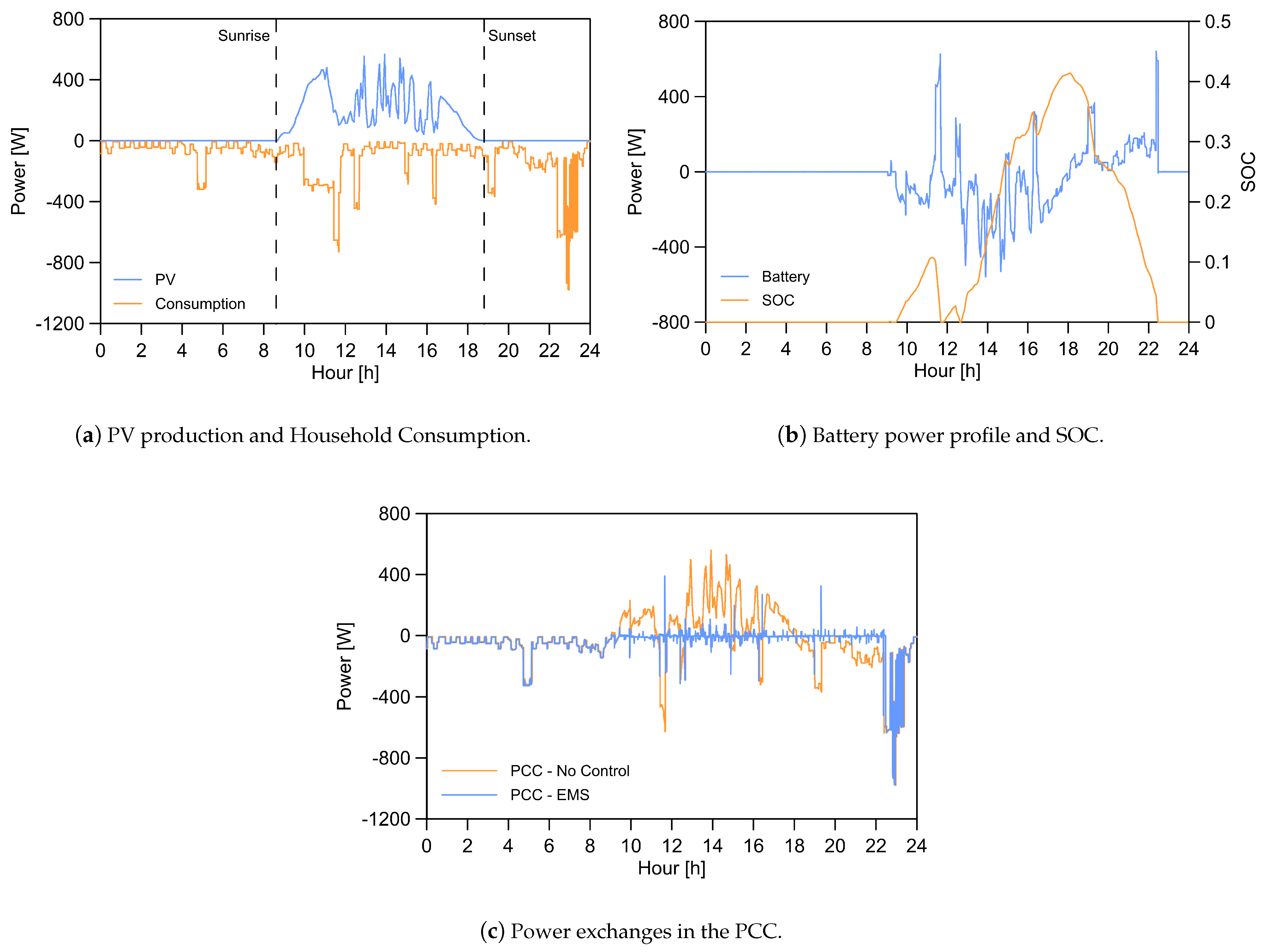
Figure 11a shows the measured profiles at the output of the inverters simulating the PV generation (blue) and the household consumption (orange) respectively. The particular sunrise and sunset time, in which the PV production is comprised, as well as the intraday variability, can be observed. This intraday variably corresponds to a cloudy day so the control system is tested under non-ideal conditions. Likewise, the consumption profile (orange) follows the expected trend with low demand during the night hours and high consumption in the morning and evening. Moreover, due to the high resolution of the synthetic profiles used in the test, the individual activation and deactivation times of the appliances are captured.
The system controlled by the EMS, that is the ESS, is shown in
Figure 11b where its power profile (blue) together with the SOC (orange) are represented. As mentioned before, the ESS is considered depleted at the beginning of the test, which means the SOC value is initially zero. Regarding this assumption, the ESS cannot provide any energy before it is charged by the excess PV production. When this occurs, its charging and discharging values clearly follow the difference between PV production and household consumption. This demonstrates the validity of the proposed communication infrastructure since the power references of the ESS, which are remotely governed by the EMS, should aim to minimise the power injected or imported from the grid.
Finally, the correct operation of the EMS is also corroborated by the power exchanges at the PCC, shown in
Figure 11c. The orange chart represents the power exchange at the PCC for the baseline scenario, meaning without an ESS system controlled in real-time by the proposed remote EMS. As can be observed, there is no compensation for the variations in PV generation and consumption, and the excess or deficit energy is either exported or imported respectively. On the other hand, the graph indicating the PCC power when the remote EMS is used (blue), clearly shows how the amount of energy exchanged with the grid is minimised.
These results can also be demonstrated numerically by comparing the base scenario with the MQTT-based EMS system.
Table 3, includes a comparison between the instantaneous measured PCC power exchange values in both cases. The second and third columns indicate the reference power values of PV generation and consumption, which are common for the base and the EMS case.
In
Table 3, reductions are observed for the average, minimum, and maximum values when utilizing the EMS-controlled system. The is due to the achievement of internal power balancing which means the power excesses or deficits are not required to be compensated by the grid at every instant.
These results prove the potential of this communication architecture to minimise the power flow through the PCC by managing the ESS charge and discharge with very high resolution (even when the experiment is downsized). It should be noted that the peaks in the PCC power profiles are a consequence of the EMS being asynchronous, which means it reacts to the power changes that occur in the PV output and the user consumption, a situation which, is totally aligned to a real-world scenario.
5.5. System Performance Analysis with Large Latencies
After presenting the experiment results for normal communication operational status, in this subsection, the system behavior’s under problematic situations due to intentional or unintentional communication malfunctions that cause abnormal levels of latencies are described.
Although the latency analysis illustrated in
Figure 9 proved that most packets are delivered within less than 350 ms, in real-world applications the situation can be much different. For example, a very busy wireless channel, congested by numerous users, may suffer from MAC delays since the users cannot gain access to the channel adequately and instantly. Other types of delays can also happen due to possible flooding situations in the network and transport layers. In any case, the effect of severe delays on the MG management structure must be investigated.
In the case of normal operation when PV generation, consumption, and ESS-SOC measurements are properly received at the EMS, it can calculate new power references in order to maintain the internal energy balance of the MG. Subsequently, if the ESS controller adequately receives these references, a new power setpoint will be reached. Therefore, the operation of the EMS is asynchronous, which explains the existence of transient peaks in the PCC power flow,
Figure 11c.
Here, latencies are emulated by creating some intentional delays over the stream of references from the EMS towards the ESS, while the power exchange at the PCC is recorded. These delays are created by deliberately bouncing the packets with the reference update among a series of intermediate MQTT topics. These topics are specifically generated solely for introducing latencies and play no other role in the system. In this way, a certain base level of delay can be imposed on the system without altering the intrinsic operation of the MQTT protocol. Other than the method used here, latencies can be emulated by using software-based sleep-type functions on both the EMS and the ESS transceivers. However, these solutions may cause computational and processing inconsistencies, besides, these approaches, cannot be considered real enough to contain much experimental value.
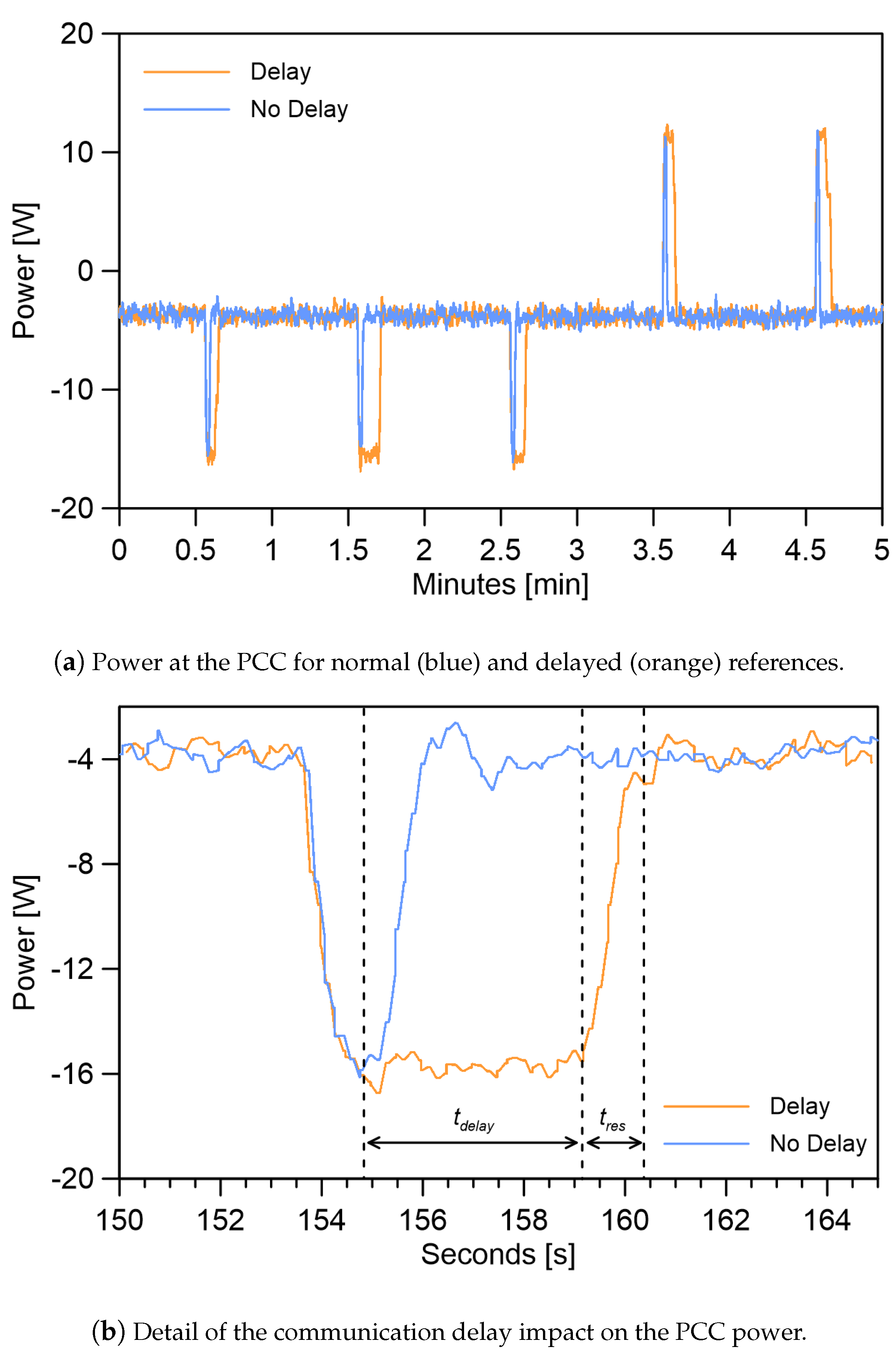
Figure 12a illustrates the effect of these latencies on the PCC power exchange for a base delay of 5 s. As can be observed, the time duration of each power exchange is increased in comparison with the case of no delay. Besides, to visualise the effect of these delays more efficiently,
Figure 12b illustrates the third PCC power peaks of
Figure 12a with higher resolution. As the communication delay increases, the peaks observed in the PCC are no longer a product of the intrinsic system update rate and reaction time (
) but actual power exchanges, which last for a few seconds and occur for the duration of the additional delay (
). In other words, if a delay happens in our communication system, the PCC will compensate for the power imbalance and inject or consume the appropriate amount of energy needed in order to maintain a balanced MG, increasing the energy exchanges with the grid.
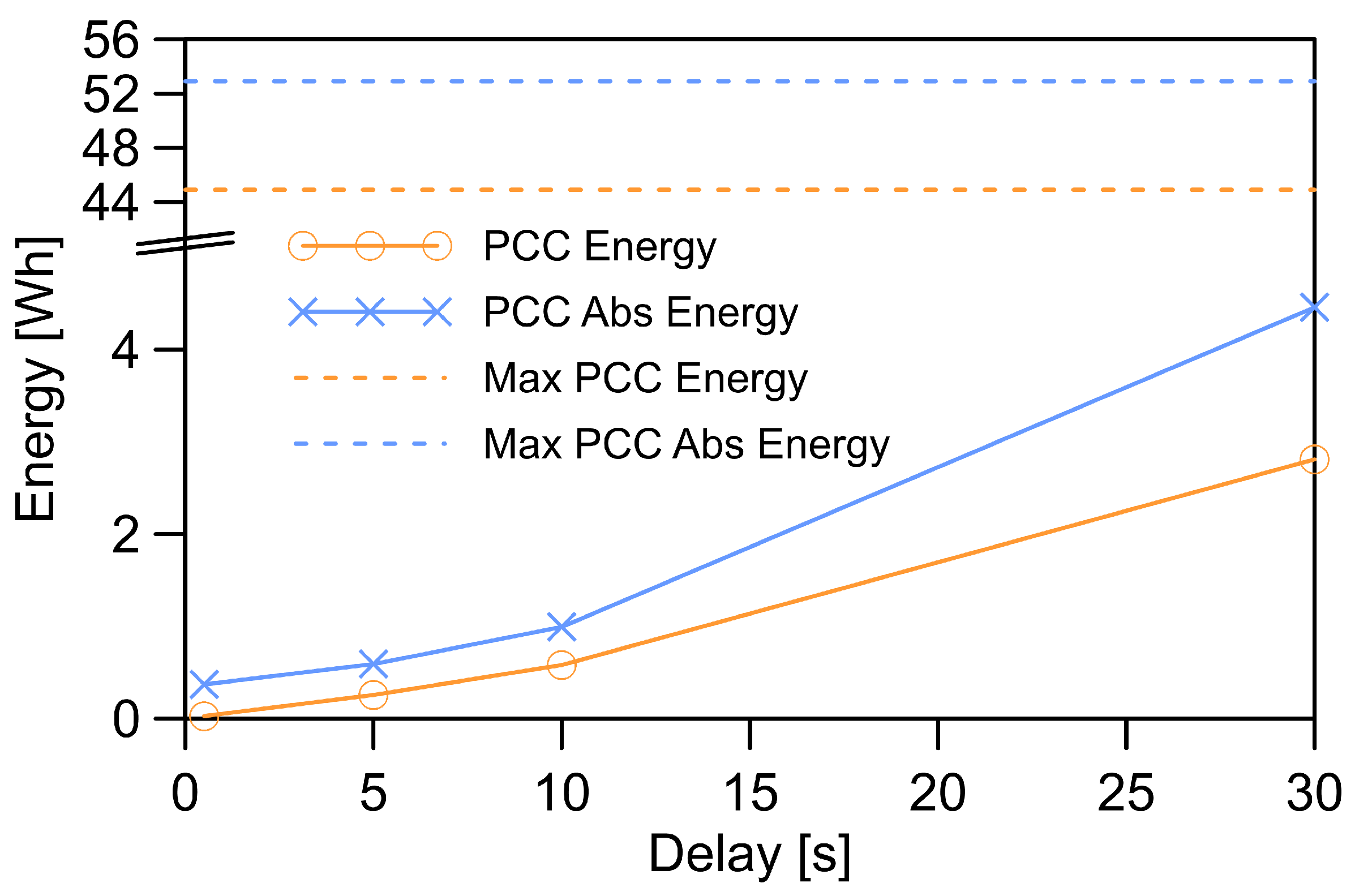
To characterise the impact of the latencies in the energy exchange with the grid, further levels of delay were tested, specifically, 500 milliseconds, 5 s, 10 s, and 30 s were selected over a period of 15 min. The PCC power exchanges were measured for each case.
Figure 13 summarises the results, where the X-Axis indicates the level of delay in seconds, while the Y-Axis states the total energy exchanged with the grid for the selected 15-min period. The orange line indicates the total energy exchanged considering the direction (import/export), while the blue line illustrates the absolute energy. As was expected, increasing levels of delay result in higher energy exchange with the grid. Nevertheless, the levels of delay introduced here aim to demonstrate the tolerance of the system since, in normal operation, latencies over one second are the exception rather than the norm.
In order to contextualize the energy levels given in
Figure 13, the maximum energy exchanges with the grid in this time interval are also indicated (dashed lines). These maximum values are calculated for both the (import/export) and absolute energy, and correspond to the no-control situation. This is the same as an MG scenario with no EMS and ESS, where all the internal energy unbalances are compensated by the PCC energy exchange with the stiff-grid. As it can be observed, the maximum energy measures are far greater than the same values for a system with a slow communication system, even when the delays are at their highest level of 30 s.
5.6. Communication Link Loss
Following the discussions regarding the effect of large communication latencies on the MG system response provided before, at this point the extreme situations of total link losses are examined and analysed.
A link failure is always a possibility in real scenarios due to technical problems with nodes, power outages, human error, or even denial of service (DoS) cyber-attacks. The link loss in these tests are emulated by shutting down the EMS which is coded as a Node.js application on an independent PC. In this way, since the EMS is no longer operational, no updated power references can be transmitted to the ESS. The link loss could be emulated by different ways such as manipulating the MQTT broker or disabling the WiFi network. However, since the new consumption and generation setpoints transmissions and the data-logging procedure also depend on the MQTT infrastructure and the recorded data is required for post-analysis, shutting down the EMS was considered as the best option.
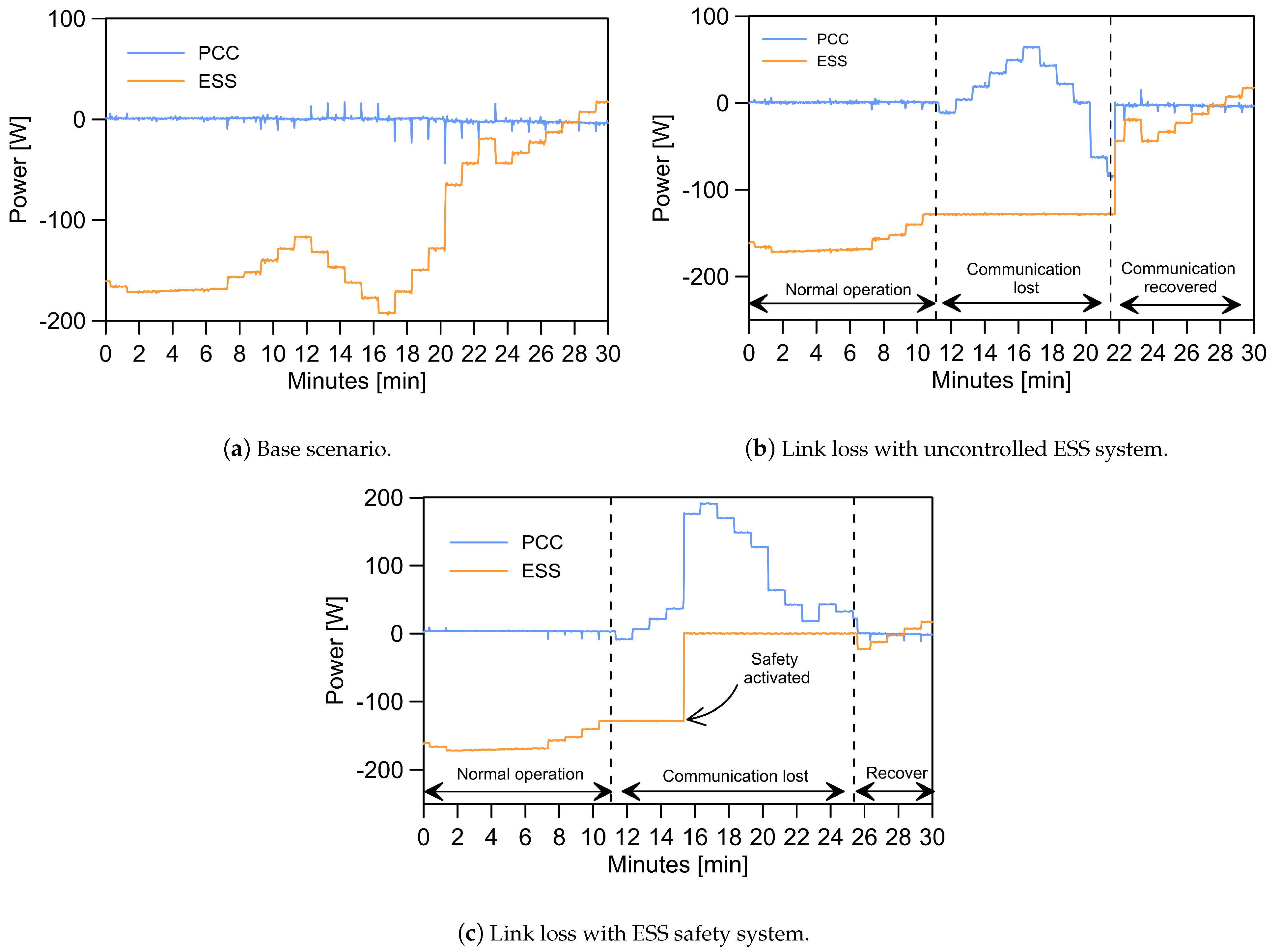
In these tests, the PCC power exchange, and ESS power measurements are recorded for a period of thirty minutes in three different scenarios:
- 1.
Base scenario: The communication link operates as expected for the duration of the experiment.
- 2.
Link loss and uncontrolled charge/discharge: A link failure takes place after ten minutes of normal operation. During the failure, no additional measures are taken locally by the ESS controller, which keeps operating with the latest received power setpoint. Eventually, the communication is re-established after ten minutes. This type of behavior can be accepted if the charge controller detects the SOC and automatically reduces the power when the ESS is fully charged or discharged.
- 3.
ESS safety system: As in case 2, the link operates for ten minutes and then fails. In this case, however, the ESS safety system, explained in
Section 4.2.5 is activated after more than five minutes without an update in the power setpoint. Subsequently, the safety system shuts down the ESS and the operation continues. Finally, the communication link is recovered after ten minutes.
The results are illustrated in
Figure 14, where for each of the test cases the power exchange at the PCC (blue) and the ESS power setpoint (orange) are represented for 30 min.
As can be observed in
Figure 14a, transient power exchange at the PCC occurs when the ESS system compensates for a change between PV generation and consumption by changing its reference. When the link totally fails, the ESS setpoints are no longer updated. This is the case in
Figure 14b,c. In the first case, the system will continue to operate with its last received reference as can be observed in
Figure 14b. In this situation, any change in the PV production and/or consumption creates an energy imbalance inside the MG that is not compensated. Thus, the MG will consume or inject power into the grid depending on the total balance, which now includes the non-responsive residual power setpoint in the ESS. In the second case, represented in
Figure 14c, a similar link failure occurs. Nevertheless, instead of leaving the system operating at the last setpoint, the power is restored to a known safe state after a timeout of 5 min or more. This can results in higher imbalances at the PCC, as is the case in this particular example. However, the safety mechanism guarantees a deterministic behavior of the system, which is independent of the length of the failure and the last known status.
It has been proven that due to the grid-connected nature of the system, the power supply is maintained even in the case of total communication failure. Hence, a communication loss will only result in a higher injection or consumption rate. Moreover, the system stability is also guaranteed since the inner control and synchronization (PLL) loops only depend on local measurements, being completely communication-free.
6. Conclusions
In this study, a communication framework that fulfills MG management requirements has been proposed. In this infrastructure, MQTT protocol was used to create the communication link between a group of smart devices, physically connected via WiFi. The solution combines an easy to deploy and cheap physical layer communication technology, with a lightweight and robust application layer protocol. Having the developed architecture, the problem of cooperatively communicating a set of inverters in an MG system has been tackled in a flexible and reliable manner.
This MG control structure has been based on grid-feeding inverters and operates in grid-connected mode. As a change in the demand or generation occurs, it has been shown how the aforementioned grid-feeding inverters are able to update their power references to optimally operate with respect to the changes. To perform this task, the proposed communication system has been used to create a link between the power inverters and an EMS. In addition, the use of the MQTT protocol has decoupled the role of publishers and subscribers of information, providing simplicity and plug-and-play features for the whole communication structure.
As a main contribution, this paper has demonstrated how tertiary control techniques, which compensate for production and consumption within an MG, can be implemented in a seamless way by using novel IoT communication capabilities. This communication system is not only easy to integrate into the MG control system, but also foster scalability. On top of that, the use of channels (topics) and the publisher/subscriber model implies that the communication possibilities are not limited to the centralised EMS presented here, but that decentralised or distributed system can also be implemented by creating an adequate set of topics.
In order to guarantee safe ESS performance and system stability in case of anomalous operation conditions such as large communication delays or a total link failure an additional safety feature has been included in the architecture. This safety system is implemented in the local controller of the ESS and is independent of the communication system and its protocols.
Based on the finding of this study, the use of MQTT as an application layer protocol to create a communication framework for grid-connected AC MG control and management is highly recommended. Simple to implement and off-the-shelf micro-python enabled microcontrollers can be used to create MQTT nodes that have low-power consumption and are cost-effective. MQTT broker can be hosted by tiny and affordable computers such as Raspberry Pi devices. Regarding that MQTT is designed to work over TCP/IP the whole system can be structured to operate over WiFi-based LANs which adds to the practicality and ease of implementation even further.
Considering the wireless communication network of the experimental testbed, the authors believe that although the devices are placed in close proximity the main proven concept which is the integration of an IoT-based communication system in MG control and management is valid. This is due to the fact that experimental circumstances were real and other users were also connected and using the same WLAN, so the wireless network was not totally controlled. However, the network was not overloaded or congested, and also the physical layer protocol (IEEE 802.11) was of short-range type. The real-world situations can be indeed very different and that is the reason why we emulated and tested the system behavior under problematic situations.
With this in mind, future work will consider other MG configurations and their communication requirements. For instance, the management of large-scale MGs whose DGs, loads, and ESSs are widely separated will be investigated. This will require looking into other types of physical layer protocols such as low power wide area network (LPWAN) technologies.


