
Multi-Parameter Optimization of Efficiency, Capital Cost and Mass of Ferris Wheel Turbine for Low Wind Speed Regions


1
African Centre of Excellence, Energy for Sustainable Development, University of Rwanda, Kigali P.O. Box 4285, Rwanda
2
School of Engineering, University of KwaZulu Natal, Durban 4041, South Africa
3
George W. Woodruff School of Mechanical Engineering, Georgia Institute of Technology, Atlanta, GA 30332-0405, USA
*
Author to whom correspondence should be addressed.
Energies 2021, 14(19), 6217; https://0-doi-org.brum.beds.ac.uk/10.3390/en14196217
Submission received: 28 June 2021
/
Revised: 30 July 2021
/
Accepted: 4 August 2021
/
Published: 29 September 2021
(This article belongs to the Special Issue Advances in Sustainable Energy and Environmental Economics)
Abstract
:The design and development of wind turbines in low-wind-speed areas involves several technical and financial challenges related to maximizing conversion efficiency and minimizing cost. Unfortunately, much of the African continent is dominated by low-wind-speed resources. In this study, a multi-parameter optimization method is used to explore the design of a novel Ferris wheel wind turbine (FWT) technology, which has an 800-kW generation capability. We used the tip speed ratio, lift-to-drag ratio and power coefficient to determine the optimal efficiency by varying the number of blades and rim diameters. The capital cost estimates, as affected by rim diameter and the number of blades, are presented. This paper studies FWTs at their rated wind speeds because wind turbines have their maximum performance at the rated wind speeds, and this allows one to observe the effects of changing the rim diameter and the number of blades without the need to consider the location of the turbine. The results show that reducing the number of spokes by half (from 64 to 32) on the four rim diameters studied decreases the efficiency by less than 0.19%, while reducing the acquisition cost by 42%, installation cost by 42% and mass by 28%. Reducing the number of spokes to a quarter (i.e., from 32 to 16) decreases the efficiency by less than 0.31%, reduces the acquisition and installation costs by 36% and 35.5%, respectively, and the mass by 19.2%, of the four rim diameters studied. The reduction of the number of blades has a significant effect on the efficiency and capital cost with varying rim diameters. This paper shows the potential for Ferris-wheel-based wind turbines for low-wind-speed conditions, such as those that prevail in parts of Africa.
1. Introduction
Wind energy is renewable, plentiful, widely distributed and clean. It produces no greenhouse gases during operation, consumes no water and uses little land [1,2]. Wind energy is key to combatting climate change [3]. Wind technology is the most established technology to meet the demands for the more efficient and affordable production of renewable energy [4]. Many countries, such as the United States, Germany, Spain and the Netherlands, have invested heavily in wind energy because of its relatively low carbon footprint and its potential to generate clean energy, while at the same time reducing dependency on non-renewable sources [5]. These advantages have made wind energy attractive to energy planners and engineers. The last decade has seen a rapid development in wind energy from 159,742 megawatts (MW) in 2009 [6] to 651 gigawatts (GW) at the end of 2019. The effects of the COVID-19 pandemic on the market for wind turbines are still to be quantified [7].
Wind turbines are designed for specific wind conditions. The IEC 61400-1 standard defines wind classes according to wind speed. Currently, classes I, II and III correspond to high, medium and low wind speed locations, respectively. In the global wind energy market, wind turbines installed in high-wind-speed sites (class I) have progressively lost their market share for the past few years in favor of wind turbines in low-wind-speed locations (class III), mainly because wind farms with low-quality wind resources are far more plentiful than high-quality ones and have advantages such as proximity to the existing electrical grid and locations of use [8,9].
The design and development of wind turbines in low-wind-speed areas involves several technical and financial challenges related to maximizing energy conversion efficiency and minimizing the cost of energy [10]. For the most part, the African continent is dominated by low wind speeds, especially those countries between the tropics of Cancer and Capricorn [11], which has made the development of wind energy difficult. Twenty-five countries in the African continent are experiencing energy crises, which may be addressed by harnessing untapped wind energy [12].
Most conventional, three-blade, horizontal-axis wind turbines (HAWT) require wind speeds greater than those available in most parts of the African continent to generate electricity. Typical turbines begin producing electricity at cut-in speeds of 3–5 m/s [13] and reach their rated power outputs at 12.3–16 m/s [14]. Wind speeds lower than the cut-in speed will result in lower wind power outputs [15]. A new type of wind turbine, the Ferris wheel wind turbine technology (FWT) discussed in this paper, addresses this challenge and has the potential to be a better technology for low-wind-speed areas [16]. The FWT design has the potential to harness wind energy in Africa, integrate wind energy into the continent’s energy mix and thus contribute to the reduction of the existing energy crisis in the African continent. In this paper, we report on research aiming to optimize an FWT for low-speed-wind regions such as those in parts of the African continent. The regions and cities of interest are shown in Figure 1 to place them in context.
Multi-parameter optimization is required to design an optimally efficient wind turbine. Unfortunately, not as much research has been performed on low-wind-speed wind turbines compared to higher-wind-speed wind turbines [10]. The literature thus far has considered structural integrity, which consists of design, fabrication and performance evaluations [17]; aerodynamic performance analysis [18], which includes blade pitch angle [19], tip speed ratio [20,21] and improved blade designs and shape optimization [13,22]; wind speed and siting analysis [23]; generator torque [19]; the number of blades [24,25,26]; and tower structural design and analysis [10]. In general, the rotor blades of a wind turbine that are designed for low-wind-speed areas are longer and have higher aspect ratios, so as to acquire more wind power at reduced cost. The costs of larger rotor diameters and taller towers have a strong impact on the total cost of the wind turbine system [10].
The few previous studies on the optimization of wind turbines for low-wind-speed regions have focused on small-scale turbines and a few commercial devices. There have been various approaches to optimizing these wind turbines. Ajayi, Ojo and Vasel reviewed existing reports on rotor designs that focus on improved blade designs for enhanced turbine performance and structural integrity [13]. Nada and Al-Shahrani investigated the optimization of the structural and aerodynamic design of small wind turbines, focusing on multi-parameter objective optimization of the shape geometry while considering rapid starting, efficient power extraction, low noise and minimal mass [28]. Yang et al. optimized the aerodynamic and structural performance of a commercial 2.1 MW horizontal axis wind turbine (HAWT) using blade element momentum theory (BEMT) and classical laminate theory (CLT) [9].
The optimization of generators is another way to increase wind turbine performance. Assareh et al. optimized torque regulation using a radial basis function (RBF) neural network [29]. Cromack and Oscar maximized the starting rotational torque and acceleration and recommended that wind turbines should have a large rotor diameter and a small generator capacity when situated in low-wind locations [30]. Gitano-Briggs designed a small wind turbine for low-wind-speed regions, optimized the generator using wind speed as the input and power as the output, and tested it in Malaysia [31]. Rozaim et al. optimized the performance of a low-speed wind turbine for wind speeds in the range of 3–5 m/s in Malaysia using a purpose-built test rig, focusing on the maximum power coefficient (Cp) at optimal tip speed ratios (TSR) [17].
Çetin et al. assessed the optimum design speed ratio using profile type and the number of blades, proposing an optimum speed ratio for a finite, optimal number of blades [20]. Chaudhary and Roy studied the optimization of a small HAWT using the blade number and tip speed ratio using BEMT, proposing an optimum set of design parameters such as Cp, solidity, number of blades and design point tip speed ratio [32]. Yang, Chen and Pang examined an aero-structural design optimization for a commercial 2.1 MW wind turbine for low-wind-speed locations, focusing on reducing the cost of energy with the integrated optimization of rotors and towers, finding that increasing rotor diameter is less efficient than increasing the hub height for a low-wind-speed turbine [10].
Previous studies for low-wind-speed areas have focused on HAWTs and vertical-axis wind turbines. The present paper studies the FWT, exploring its design and space optimization (Figure 2). The FWT is a new and potentially better technology for low-wind-speed areas than the conventional wind turbines because of its ability to generate power less expensively at lower wind speeds. In an FWT, the blades orbit the central shaft. There are many advantages to the FWT design: the blades automatically self-pitch and self-twist to maintain the blades’ leading edges at an optimal angle of attack to achieve maximum lift [33]. In addition, it generates less sound, is safer for birds and bats, and can be built less expensively using locally available materials [34].
The FWT comprises a rim, wire, hub, blade, generator, tower and foundation. It does not have a gearbox, nacelle or pitch system. The blades are mounted on the wire spokes that form the Ferris wheel structure, so as not to expose the wire to the wind loading and create turbulence. In this paper, we investigate the optimization of an FWT for low-speed regions. Its multi-parameter optimization uses an 800 kW FWT as a case study and focuses on the effect of changing the rim diameter and the number of blades on the power output, efficiency, mass and capital cost of acquisition of the wind turbines. This research is innovative in that it provides the optimal sizing and selection of the FWT for specific regions in the African continent and other low-wind-speed regions globally.
2. Methodology
2.1. Multi-Parameter Model Development
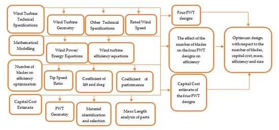
The elements comprising the multi-parameter optimization model are shown in Figure 3 and include the following:
- Mathematical modelling: The mathematical equations for the multi-parameter optimization are presented. This allows one to study the effect of the input parameters on the output parameters.
- Wind turbine design specifications: The geometry and the technical specifications of the FWTs are discussed. The rated wind speed of the designs is calculated using the geometry and the appropriate equations. Estimating the rated wind speed of the FWTs helps to evaluate their designs based on the input parameters.
- Number of blades versus efficiency optimization: The effect of the reduction of the number of spokes and blades on the efficiency is analyzed with varying rim diameters.
- Capital costs estimate: The capital cost is estimated using the weight and materials of each part of the wind turbine. We also study the effect of the reduction of the number of blades on the weight and the capital cost.
- Number of blades versus capital cost: The effect of the reduction of the number of blades is studied on the capital cost, installation cost and the mass of the FWTs.
Using this method, a multi-parameter optimization model has been developed and used to study the design of FWTs. The rest of this paper details the processes and results.
2.2. Mathematical Modeling
This section presents the governing equations used to optimize the FWT designs and their input and output parameters. These equations include the wind power equations, the techno-economic equations, the number of blades and the efficiency equation. The power that a wind turbine can extract from the wind is given by Equation (1) [35]
where ρ is the air density, which normally ranges from 1.22 to 1.3 kg/m3, A is the area swept by the turbine blades (m2) and equals πr2 with the radius, r, equal to the blade length (l), and V is the actual wind speed (m/s). Each turbine has a unique power coefficient, Cp, which is a function of wind speed. The Betz limit places a limit on the performance (efficiency) of a wind turbine so that is 59% [36]. Once the various engineering requirements of a wind turbine, such as strength and durability, are incorporated, then the real-world limit is below the Betz Limit. Hence, incorporating the power coefficient into Equation (1) results in the available power extractable from the wind, as given by Equation (2) [37]
The maximum theoretically possible power coefficient for wind turbines can be determined as a function of tip speed ratio (λ), expressed as Equation (3) [38,39]
where ω is the angular velocity in rad/secs (rad/s), r is the maximum rotor radius of the wind turbine in meters (m), and v is the wind speed in m/s. The angular velocity, ω, can be determined using Equation (4)
where T is the revolutions per min (rpm) and π is a numerical constant. The relationship between efficiency, tip speed ratio and the number of blades is given by Equation (5) [40]
where is the maximum achievable power coefficient and B is the number of blades.
2.3. Wind Turbine Design Specifications
In this section, the FWT designs, which have different rim diameters and swept areas, are analyzed. The rated wind speeds of the FWT designs are calculated using Equation (2) and the input variables shown in Table 1. The FWT with a 61 m (200 ft) rim diameter represents the prototype manufactured by the Barber Wind Turbines. The FWT designs studied had four different rim diameters, 61 m (200 ft), 73 m (240 ft), 88 m (290 ft) and 104 (341 ft) and an 800 kW generation capability. These rim diameters were chosen to represent commercially available turbines of this power capacity.
The four FWT designs are modeled at their rated wind speeds because they exhibit their maximum performance at the rated wind speeds and this allows one to observe the effects of changing the rim diameter and the number of blades without the need to consider location. Furthermore, the rated wind speeds of the wind turbines decrease with increasing swept area.
2.4. Model Inputs and Outputs
This section describes the assumptions and parameters that were used in the techno-economic model to determine the optical FWT configurations. The assumptions include the following:
- The hub design is constant.
- The tower design is constant.
- The foundation of the wind turbine design varies depending on the weight of the wind turbine.
- The blade spoke configurations vary between 64 (control design), 32 and 16 spokes.
- The wind turbine designs have different numbers of blade elements depending on the rim diameter and spoke length.
- The rims of the different wind turbine designs have the same cross-sectional area but different lengths.
- The wind turbine designs also have varying wire/spoke lengths depending on the rim diameter.
The model’s input parameters that were varied are shown in Table 2. The rim diameter was varied because it directly affects the ability of the wind turbine to capture energy. The number of spokes was varied to determine the effect of changes in the number of blades. The spokes are made from wire ropes. The blade elements completely cover the spokes, thereby reducing wind resistance; this leads to a varying number of blade elements, corresponding to the number of spokes and the rim diameter (see discussion of Table 3). The individual blade elements are in the shape of a proprietary air foil and are 200 mm (8 inches) wide and 1.5 m (5 feet) long. The spokes are threaded through the blade elements at a critical point so that the aerodynamic shape of the blades forces them to rotate and maintain a critical angle of attack relative to the local wind flow. The segmentation of the blades allows the blade to twist from rim to hub in response to its rotational speed and hence maintain an optimal configuration.
The capacity of the generator was fixed at 800 kW because that represents a size between commercial generators, which are typically 1.5 MW or more, and small windmills, which typically have less than a 50 kW capacity. The rim is made of hollow, rectangular extruded aluminum, whereas the spokes are steel wire rope, the hub is fabricated from steel and the blades are made from pultruded glass-fiber composite. The model outputs the efficiency, the mass and the cost of the wind turbine. The variation of the input parameters effects the mass of the wind turbine, its capital cost and its efficiency. In turn, these affect the cost of electricity generation.
3. Optimization of FWT Efficiency with the Number of Blades
In this section, the effect of varying the number of blades on the efficiency of the FWTs is determined by calculating the tip speed ratio, lift-to-drag ratio, and the coefficient of performance. The efficiency of a wind turbine depends on the airfoil characteristics of the wind turbine blades. The tip speed ratio effects the blade’s ability to capture power and its overall efficiency. The maximum theoretically possible power coefficient for wind turbines is determined as a function of the tip speed ratio. The number of blade elements for each design is calculated based on the rim diameters and the length of the wire spokes. Table 3 presents the spoke and blade configurations under study.
Using Equation (3), the angular velocity (ω) was estimated by substituting revolutions per minute (N). Subsequently, the tip speed ratio (λ) for the four FWT designs are calculated by substituting the angular velocity (ω), the maximum rotor radius of the wind turbine (r) and the wind speed (v) into Equation (4) and presented in Table 4, except for the revolutions per minute (N), which are obtained from the manufacturer (Barber Wind Turbines) [16].
Here, the is directly proportional to the tip speed ratio, and the tip speed ratio is a function of the lift-to-drag ratio and the number of blades. For grid-connected wind turbines with three rotor blades, the reported optimal wind tip speed ratio is seven, with a range of 6–20 [20,21,41,42,43]. The tip speed ratios of 5.36–13.0 calculated for the FWTs fit within the reported range, except for the 61 m (200 ft) turbine, of which the tip speed ratio value is slightly less than the lower bound value of this optimal reported range. Using Equation (5), the values calculated for Cl/Cd for the FWTs range between 16 and 40 (Table 4). Similarly to the tip speed ratio results, the 61 m (200 ft) FWT has a Cl/Cd value which is slightly less than the reported range of 25 to infinity for a finite number of blades [40], whereas the other three FWT designs fit into this range. The maximum achievable power coefficient is calculated as a function of the number of blades using Equation (5) and the results are displayed in Figure 4. As can be seen in Table 5 and Figure 4, as the number of spokes and blades decreases, decreases but not significantly. The very small effect of reducing the number of spokes with a constant tip speed ratio and the lift-to-drag ratio (Cl/Cd) is evident.
Considering Figure 4 in more detail, one observes that the rim diameter and hence the number of spokes affect the efficiency of the FWTs. A reduction in the number of spokes reduces the number of blades and hence reduces . Reducing the number of blades reduces the efficiency of the wind turbine. As the number of blades decreases, the effect that varying the number of blades has on tends to increase. The largest decrease is seen for the 61 m (200 ft) rim from 32 spokes (640 blade elements) to 16 spokes (320 blade elements), whereas the smallest decrease is for the 104 m (341 ft) rim from 64 spokes (2182 blade elements) to 32 spokes (1091 blade elements). However, with increasing rim diameter, the effect of reducing the number of spokes and blades on the decreases. Hence, reducing the number of spokes and blades does not have a significant effect on efficiency. Over the range of spoke and blade numbers studied, the efficiency is reduced by less than 0.31%, which would be the same result as that of using longer spokes, which have the benefit of increased power [10].
4. Capital Cost Calculations
In order to determine the effect of variations in the number of blades on the mass of the FWTs and on the cost of the FWTs, the capital costs of the four FWTs can be calculated by (1) determining the geometry of the designs’ components, (2) selecting their materials, (3) estimating the cost of the materials, and then (4) determining the cost of the entire design.
The geometry of each part of the base FWT—the rim, spokes, hub and blades of the 61 m (200 ft) rim with an 800 kW generator—was obtained from Barber, 2020 (Personal communication). To create the three other designs, the rim, spokes and blades were scaled up by enlarging the geometry of the parts linearly, subject to the following assumptions. The hub and tower designs remained constant throughout the wind turbine designs. The rims have the same cross-sectional area but different lengths. The spoke wire diameter remains constant and only the lengths vary with the rim diameter. The blade cross-section also remains constant. The number of blade elements varies depending on the rim diameter and hence the spoke length. The spoke configurations are 16, 32 and 64 (nominal design) spokes.
The materials that can be used for the manufacture of each part of the wind turbine are identified and the most suitable material is selected. The material selection is made based on the mechanical properties of the materials, their suitability for the wind turbine part, their availability in the regions of the African continent studied and their cost. These and their costs are listed in Table 6.
The mass of each of the FWT parts can be calculated from the geometry and dimensions of the parts of the wind turbine. This analysis focuses only on the rotational components of the wind turbine, which include the rim, wire spokes, hub and blades. The tower and foundation are assumed to be the same for each design; this simplifies the analysis, but does not negate the power of the analysis.
The hub consists of two concentric hollow cylindrical shafts (inner and outer), separated by an inner and an outer flange at the joining point (Figure 2). There is an inner flange at the end of the inner shaft and an outer flange at the end of the outer shaft. The dimensions of the hub are shown in Table 7. The volume of the hub was found to be 0.87 cubic meters. As the density of steel is 8050 kg/m3, the mass of the hub is 6859 kg.
The wire used was ¾-inch (19 mm) steel cables attached to the rim at 10 feet (3.1 m) intervals. Table 8 presents the wire lengths for the various rims and masses.
The rim is a 152 × 304 × 16 mm rectangular aluminum tubing. The density of aluminum is 2700 kg/m3. As the FWT designs have different swept areas, the rims of the different wind turbines have the same cross-sectional areas but different lengths. The mass of the blades, based upon the cross-sectional area of the glass fiber composite pultrusion and the length of each segment, are shown in Table 9. The volume of one blade segment is 5260 cm3. The density of the E-glass and polyester composite is 2.36 g/cm3. The mass of one pultruded blade is 12.4 kg.
5. Number of Blades Versus Capital Cost Estimate
The total material cost of each FWT design is estimated by multiplying the mass of the material of each component by the cost per mass. The capital cost or the selling price of the FWTs is estimated by scaling the estimated material cost nine times, plus the profit margin, using the material-manufacturing-selling 1-3-9 rule [47]. The installation cost was estimated as 7 percent of the capital cost of the FWTs [47]. The capital cost, installation cost and the weight of a wind turbine play an important role in the selection and acquisition of a wind turbine. The effects of the reduction of the number of blades on the capital cost, installation cost and the mass of the FWTs with varying rim diameter were studied. The results are presented in Appendix A, Appendix B and Appendix C.
5.1. Capital Cost
The capital cost estimate results show that the capital cost increases with increasing the rim diameter of the FWT designs. The results show that the capital cost decreases as the number of spokes and blades decreases with increasing rim diameter (Table 10 and Figure 5). The largest decrease in the capital cost is seen for the 88 m (290 ft) turbine from 32 spokes (928 blade elements) to 16 spokes (464 blade elements), whereas the lowest is on the 61 m (200 ft) turbine from 32 spokes (640 blade elements) to 16 spokes (320 blade elements). Reducing the number of spokes and blade elements does have a significant effect on the capital cost.
5.2. Installation Cost
The effect of the reduction of the number of spokes and blades on the installation cost of the FWTs with varying rim diameter shows that the installation cost decreases as the numbers of spokes and blades decrease with increasing rim diameter (Table 11 and Figure 6). The largest decrease in the installation cost of 42% was recorded on the 104 m (341 ft) rim for a reduction from 64 spokes (2182 blade elements) to 32 spokes (1091 blade elements), whereas the lowest decrease of 35% was seen on the 61 m (200 ft) rim from 32 spokes (640 blade elements) to 16 spokes (320 blade elements).
5.3. Mass of the FWTs
The effect of the reduction of the number of spokes and blades on the mass of the FWTs with varying rim diameter shows that the estimated mass of the FWTs decreases as the number of spokes and blades decrease with increasing rim diameter (Table 12 and Figure 7). The largest decrease in the mass of 29% was observed on the 104 m (341 ft) rim for a reduction from 64 spokes (2182 blade elements) to 32 spokes (1091 blade elements), whereas the lowest decrease of 18% was observed on the 61 m (200 ft) rim diameter from 32 spokes (640 blade elements) to 16 spokes (320 blade elements).
The optimization of the number of spokes and blades, the rim diameter and the rated wind speed of the wind turbines on the efficiency, mass and cost of the wind turbines were characterized. Overall, the efficiency, capital cost, installation cost and mass of the FWT results were consistent, thereby validating the multi-parameter optimization model. The four FWT designs studied were modeled at their rated wind speeds because wind turbines have the maximum performance at the rated wind speeds and this allows one to observe the effects of changing the rim diameter and number of blades without confounding the results due to location. The results show that, as compared to the control design (61 m (200 ft) with 64 wire spokes and 1280 blade elements), the 104 m (341 ft) rim with 32 spokes (spokes) (1091 blade elements) wind turbine shows the least decrease in efficiency, and the largest decreases in capital cost, installation cost and mass. However, the results for the 88 m (290 ft) rim wind turbine with 32 spokes (928 blade elements) are similar to those of the 104 m (341 ft) rim wind turbine with 32 spokes (1091 blade elements) in terms of capital cost, installation cost and mass, showing only a slight decrease in efficiency of 0.025%. As a result, it provides a well-balanced wind turbine design, suitable for low-wind-speed regions, such as those in the parts of the African continent studied, considering the advantages mentioned earlier, coupled with a lower rated wind speed of 7.91 m/s; a greater ease of handling, transportation and assembly; and a reduction in the mass of materials and the number of blades. Therefore, the FWT promises to be a strong candidate for harnessing wind energy in low-wind-speed areas such as those present in the regions of the African continent studied.
6. Conclusions
The multi-parameter optimization of a novel wind turbine based on a Ferris wheel technology for low-wind-speed regions was presented in this study. The input parameters studied were wind turbine rim diameter, the number of blades, and the rated wind speeds of the wind turbines. The effects of these parameters on efficiency, capital and installation cost, and the mass of the wind turbines have been presented, as well as a capital cost estimate of the four wind turbines. The four FWT designs being studied were modeled at their rated wind speeds because wind turbines have the maximum performance at the rated wind speeds and this allows one to observe the effects of changing rim diameter and number of blades without confounding the results due to location. This model is generic enough that it can be used to optimize wind turbines with other diameters and numbers of blades.
For the FWTs, the tip speed ratio was between 5.36 and 13.03, which is within the optimal range of 6 to 20, except for the 61 m (200 ft)–800 kW design. The observed Cl/Cd values of 16.3–39.3 were within the optimal range of 25 to infinity for a finite number of blades, except for the 61 m (200 ft)–800 kW wind turbine. The results show that reducing the number of blades by half on the four rim diameter designs decreased the efficiency by less than 0.31%, while potentially saving 42% in capital costs, 42% in installation costs and 28% in terms of the mass of the FWT designs. A further reduction of the number of spokes from 32 to 16 causes a 36% reduction on average in capital costs, 36% in installation costs and 19% in terms of the mass of the four FWT designs. Overall, reducing the number of spokes and blades does have a significant effect on the capital cost, installation cost and mass of the wind turbines.
The 88 m (290 ft) rim wind turbine with 32 spokes (928 blade elements) proved to be the most suitable for wind energy investments within the assumptions of this work. Considering the reduced amount of materials; lower acquisition cost; insignificantly lower energy yield; lower weight; the ease of handling, transportation and assembly; and the reduction in the number of blades, it promises to be a better design. The small reduction in its efficiency may be compensated for with the use of longer turbine blades, resulting in a wider swept area.
Further research can focus on the optimization of the wind turbines using the wind turbine rim diameter, number of blades and the rated wind speeds of the wind turbines on the performance and economics of FWTs in low-wind-speed regions. This will help to determine the techno-economic viability of wind turbines in low-wind-speed regions.
Author Contributions
Conceptualization, K.A.A. and J.S.C.; methodology, K.A.A. and J.S.C.; software, K.A.A. and J.S.C.; validation, K.A.A., N.I. and J.S.C.; formal analysis, K.A.A.; investigation, K.A.A.; resources, K.A.A. and J.S.C.; data curation, K.A.A.; writing—original draft preparation, K.A.A.; writing—review and editing, K.A.A., N.I. and J.S.C.; supervision, N.I. and J.S.C.; project administration, N.I. and J.S.C. All authors have read and agreed to the published version of the manuscript.
Funding
This research was funded by the World Bank’s Eastern and Southern Africa Higher Education Centers of Excellence Project (ACE II) and the Inter-University Council of East Africa.
Institutional Review Board Statement
Not applicable.
Informed Consent Statement
Not applicable.
Data Availability Statement
The data that support the findings of this study are available in this paper.
Acknowledgments
The authors thank Jerry Barber and Barber Wind Turbines LLC for their support, data and partnership during this research. Special thanks to the African Centre of Excellence, Energy for Sustainable Development, University of Rwanda, Kigali, Rwanda, through the World Bank ACE II program for their sponsorship. The views expressed in this paper are solely those of the authors and do not necessarily reflect the views of the World Bank or Barber Wind Turbines.
Conflicts of Interest
The authors declare no conflict of interest for the research study.
Nomenclature
| A | Swept area |
| B | Number of blades |
| BEMT | Blade element momentum theory |
| BWT | Barber Wind Turbine |
| Coefficient of lift-to-drag ratio | |
| Cp | Performance coefficient |
| Maximum achievable power coefficient | |
| Ft | feet |
| FWT | Ferris wheel wind turbine |
| HAWT | Horizontal axis wind turbine |
| kWh | Kilowatt hour |
| m/s | Meter per second |
| N | Revolutions per min |
| Π | Pi (constant = 3.14…) |
| r | Rotor radius (blade length) |
| λ or TSR | Tip speed ratio |
| v | Wind speed |
| ω | Angular velocity |
Appendix A. Cost Estimates for an FWT with 64 Spokes
| Component | Rim diameter (m) | 61 | 73 | 88 | 104 | ||||
| Rim diameter (m) | 61 | 73 | 88 | 104 | Material | Cost ($) | |||
| Rim mass (kg) | 6892 | 8378 | 10,123 | 11,904 | Aluminum alloy 6061 | 12,375 | 14,850 | 17,944 | 21,099 |
| Wire length (m) | 2903 | 3484 | 4209 | 4950 | Steel wire | 13,696 | 16,435.20 | 19,859 | 23,352 |
| Hub mass (kg) | 6859 | 6859 | 6859 | 6859 | Steel | 5376 | 5376 | 5376 | 5376 |
| Blade mass (kg) | 15,109 | 18,289 | 22,265 | 26,241 | Composite | 66,618 | 80,642 | 98,173 | 115,704 |
| Total material cost | 98,065 | 117,303 | 141,352 | 165,531 | |||||
| Capital cost | 1,400,922 | 1,675,765 | 2,019,318 | 2,364,733 | |||||
| Installation cost | 98,065 | 117,303 | 141,352 | 165,531 | |||||
Appendix B. Cost Estimates for an FWT with 32 Spokes
| Component | Rim diameter (m) | 61 | 73 | 88 | 104 | ||||
| Rim diameter (m) | 61 | 73 | 88 | 104 | Material | Cost ($) | |||
| Rim mass (kg) | 6892 | 8378 | 10,123 | 11,904 | Aluminum alloy 6061 | 12,375 | 14,850 | 17,944 | 21,099 |
| Wire length (m) | 1451 | 1742 | 2105 | 2475 | Steel wire | 6848 | 8218 | 9930 | 11,676 |
| Hub mass (kg) | 6859 | 6859 | 6859 | 6859 | Steel | 5376 | 5376 | 5376 | 5376 |
| Blade mass (kg) | 7554 | 9145 | 11,133 | 13,121 | Composite | 33,309 | 40,321 | 49,087 | 57,852 |
| Total material cost | 57,908 | 68,765 | 82,336 | 96,003 | |||||
| Capital cost | 827,253 | 982,353 | 1,176,228 | 1,371,476 | |||||
| Installation cost | 57,908 | 68,765 | 82,336 | 96,003 | |||||
Appendix C. Cost Estimates for an FWT with 16 Spokes
| Component | Rim diameter (m) | 61 | 73 | 88 | 104 | ||||
| Rim diameter (m) | 61 | 73 | 88 | 104 | Material | Cost ($) | |||
| Rim mass (kg) | 6892 | 8378 | 10,123 | 11,904 | Aluminum alloy 6061 | 12,375 | 14,850 | 17,944 | 21,099 |
| Wire length (m) | 726 | 871 | 1052 | 1237 | Steel wire | 3424 | 4109 | 4965 | 5837 |
| Hub mass (kg) | 6859 | 6859 | 6859 | 6859 | Steel | 5376 | 5376 | 5376 | 5376 |
| Blade mass (kg) | 3777 | 4572 | 5567 | 6560 | Composite | 16,654 | 20,161 | 24,543 | 28,926 |
| Total material cost | 37,829 | 44,495 | 52,828 | 61,239 | |||||
| Capital cost | 540,419 | 635,647 | 754,683 | 874,847 | |||||
| Installation cost | 37,829 | 44,495 | 52,828 | 61,239 | |||||
References
- Ahmed, S.; Ahmed, E.; Younis, S.A.; Fadel, M.T. Using wind power plants as alternative energy. Glob. J. Eng. Sci. Res. 2018, 5, 53–63. [Google Scholar]
- Jaber, S. Environmental Impacts of Wind Energy. J. Clean Energy Technol. 2014, 1, 251–254. [Google Scholar] [CrossRef] [Green Version]
- Dinh, V.N.; McKeogh, E. Offshore Wind Energy: Technology Opportunities and Challenges. In Proceedings of the 1st Vietnam Symposium on Advances in Offshore Engineering; Springer: Singapore, 2019; Volume 18, pp. 408–414, ISBN 978-981-13-2306-5. [Google Scholar]
- Katopodis, T.; Vlachogiannis, D.; Politi, N.; Gounaris, N.; Karozis, S.; Sfetsos, A. Assessment of climate change impacts on wind resource characteristics and wind energy potential in Greece. J. Renew. Sustain. Energy 2019, 11, 066502. [Google Scholar] [CrossRef]
- Faizal, M.; Chelvan, R.K.; Amirah, A. Energy, Economic and Environmental Impact of Wind Power in Malaysia. Int. J. Adv. Sci. Res. Manag. 2017, 2, 81–87. [Google Scholar]
- Adeyeye, K.; Ijumba, N.; Colton, J. Exploring the environmental and economic impacts of wind energy: A cost-benefit perspective. Int. J. Sustain. Dev. World Ecol. 2020, 27, 1–14. [Google Scholar] [CrossRef]
- Global Wind Energy Council. Global Wind Report 2019; Global Wind Energy Council: Brussels, Belgium, 2020. [Google Scholar]
- International Electrotechnical Commission. IEC 61400-1: Wind Turbines Part 1: Design Requirements, 3rd ed.; International Electrotechnical Commission: Geneva, Switzerland, 2005; Volume 08. [Google Scholar]
- Yang, H.; Chen, J.; Pang, X.; Chen, G. A new aero-structural optimization method for wind turbine blades used in low wind speed areas. Compos. Struct. 2019, 207, 446–459. [Google Scholar] [CrossRef]
- Yang, H.; Chen, J.; Pang, X. Wind turbine optimization for minimum cost of energy in low wind speed areas considering blade length and hub height. Appl. Sci. 2018, 8, 1202. [Google Scholar] [CrossRef] [Green Version]
- Mentis, D. Wind Energy Assessment in Africa A GIS-Based Approach. Master’s Thesis, KTH School of Industrial Engineering and Management Energy Technology, Stockholm, Sweden, 2013. [Google Scholar]
- Mukasa, A.; Mutambatsere, E.; Arvanitis, Y.; Triki, T. Development of Wind Energy in Africa; Working Paper Series No 170; African Development Bank Group: Tunis, Tunisia, 2013; pp. 1–43. [Google Scholar]
- Ajayi, O.O.; Ojo, O.; Vasel, A. On the need for the development of low wind speed turbine generator system. IOP Conf. Ser. Earth Environ. Sci. 2019, 331, 1–12. [Google Scholar] [CrossRef]
- AWEO. Size Specifications of Common Industrial Wind Turbines, in Technical Specifications of Common Large Wind Turbines, 2018. Available online: http://aweo.org/windmodels.html (accessed on 26 June 2018).
- Weber, J.; Gotzens, F.; Witthaut, D. Impact of strong climate change on the statistics of wind power generation in Europe. Energy Procedia 2018, 153, 22–28. [Google Scholar] [CrossRef]
- Barberwind Turbines. Turbine Specifications. Available online: https://www.barberwindturbines.com/the-turbine/turbine-specifications (accessed on 6 February 2020).
- Rozaim, M.F.; Fazila, M.Z.; Nor, N.S.M.; Kamar, H.M.; Kamsah, N. Experimental study on performance of low speed wind turbine for application in Malaysia. J. Adv. Res. Fluid Mech. Therm. Sci. 2016, 26, 20–28. [Google Scholar]
- Khlaifat, N.; Altaee, A.; Zhou, J.; Huang, Y.; Braytee, A. Optimization of a Small Wind Turbine for a Rural Area: A Case Study of Deniliquin, New South Wales, Australia. Energies 2020, 13, 2292. [Google Scholar] [CrossRef]
- Zhang, Z. Performance Optimization of Wind Turbines. Ph.D. Thesis, University of Iowa, Iowa City, IN, USA, 2012. [Google Scholar]
- Çetin, N.S.; Yurdusev, M.A.; Ata, R.; Özdemir, A. Assessment of optimum tip speed ratio of wind turbines. Math. Comput. Appl. 2005, 10, 147–154. [Google Scholar] [CrossRef]
- Yurdusev, M.A.; Ata, R.; Çetin, N.S. Assessment of optimum tip speed ratio in wind turbines using artificial neural networks. Energy 2006, 31, 2153–2161. [Google Scholar] [CrossRef]
- Xudong, W.; Shen, W.Z.; Zhu, W.J.; Jin, C. Shape Optimization of Wind Turbine Blades. Wind Energy 2009, 12, 781–803. [Google Scholar] [CrossRef]
- Cetinay, H.; Kuipers, F.A.; Guven, A.N. Optimal siting and sizing of wind farms. Renew. Energy 2017, 101, 51–58. [Google Scholar] [CrossRef] [Green Version]
- Predescu, M.; Bejinariu, A.; Mitroi, O.; Nedelcu, A. Influence of the Number of Blades on the Mechanical Power Curve of Wind Turbines. Int. Conf. Renew. Energies Power Qual. 2009, 1, 825–830. [Google Scholar] [CrossRef] [Green Version]
- Adeyeye, K.; Ijumba, N.; Colton, J. The Effect of the Number of Blades on the Efficiency of a Wind Turbine. In Proceedings of the IOP Conference Series: Earth and Environmental Science, 2021 11th International Conference on Future Environment and Energy, Tokyo, Japan, 28–30 January 2021; Volume 801, pp. 012020-1–012020-8. [Google Scholar]
- Mühle, F.; Adaramola, M.S.; Sætran, L. The effect of the number of blades on wind turbine wake—A comparison between 2-and 3-bladed rotor. J. Phys. IOP Conf. Ser. 2016, 753, 1–10. [Google Scholar] [CrossRef] [Green Version]
- Adeyeye, K.A.; Ijumba, N.; Colton, J.S. A techno-economic model for wind energy cost analysis for low wind speed areas. Processes 2021, 9, 1–24. [Google Scholar]
- Nada, A.A.; Al-shahrani, A.S.; Nada, A.A.; Al-shahrani, A.S. Shape Optimization of Low Speed Wind Turbine Blades using Flexible Multibody Approach. Energy Procedia 2017, 134, 577–587. [Google Scholar] [CrossRef]
- Assareh, E.; Poultangari, I.; Tandis, E.; Nedaei, M. Optimizing the wind power generation in low wind speed areas using an advanced hybrid RBF neural network coupled with the HGA-GSA optimization method. J. Mech. Sci. Technol. 2016, 30, 4735–4745. [Google Scholar] [CrossRef]
- Cromack, D.E.; Oscar, D. Design Optimization of Small Wind Turbines for Low Wind Regimes. J. Sol. Energy Eng. Trans. ASME 1984, 106, 347–350. [Google Scholar] [CrossRef]
- Gitano-Briggs, H. Low Speed Wind Turbine Design. In Advances in Wind Power; Rupp Carriveau, IntechOpen, 2012; Available online: https://www.intechopen.com/chapters/41081 (accessed on 25 June 2021).
- Chaudhary, M.K.; Roy, A. Design & optimization of a small wind turbine blade for operation at low wind speed. World J. Eng. 2015, 12, 83–94. [Google Scholar]
- Barberwind Turbines. Features and Benefits, 2018. Available online: http://www.barberwindturbines.com (accessed on 1 November 2018).
- Alternative Energy News. The Lateral Axis Wind Turbine in Energy Inventions/Wind Power/Wind Turbines, 2018. Available online: http://www.alternative-energy-news.info/lateral-axis-wind-turbine/ (accessed on 26 September 2018).
- Rao, K.R. Wind Energy for Power Generation: Meeting the Challenge of Practical Implementation; Springer Nature Switzerland: Cham, Switzerland, 2019. [Google Scholar]
- Ben Ahmed, M.; Boudhir, A.A. Innovations in Smart Cities and Applications. In Proceedings of the 2nd Mediterranean Symposium on Smart City Applications, Tangier, Morocco, 15–27 October 2017; pp. 1–1046. [Google Scholar]
- Sarkar, A.; Behera, D.K. Wind Turbine Blade Efficiency and Power Calculation with Electrical Analogy. Int. J. Sci. Res. Publ. 2012, 2, 1–5. [Google Scholar]
- Poultangari, I.; Shahnazi, R.; Sheikhan, M. RBF neural network based PI pitch controller for a class of 5-MW wind turbines using particle swarm optimization algorithm. ISA Trans. 2012, 51, 641–648. [Google Scholar] [CrossRef]
- Habibi, H.; Howard, I.; Simani, S. Reliability Improvement of Wind Turbine Power Generation using Model-based Fault Detection and Fault Tolerant Control: A review. Renew. Energy 2019, 135, 877–896. [Google Scholar] [CrossRef]
- Manwell, J.F.; McGowan, J.G.; Rogers, A.L. Wind Energy Explained Theory, Design and Application, 2nd ed.; John Wiley & Sons Ltd: West Sussex, UK, 2009. [Google Scholar]
- Ragheb, M. Optimal Rotor Tip Speed Ratio. Working Notes. 2009. Available online: https://users.wpi.edu/~cfurlong/me3320/DProject/Ragheb_OptTipSpeedRatio2014.pdf (accessed on 1 July 2020).
- Bakırcı, M.; Yılmaz, S. Theoretical and computational investigations of the optimal tip-speed ratio of horizontal-axis wind turbines. Eng. Sci. Technol. Int. J. 2018, 21, 1128–1142. [Google Scholar] [CrossRef]
- Ragheb, M.; Ragheb, A.M. Wind Turbines Theory-The Betz Equation and Optimal Rotor Tip Speed Ratio. In Fundamental and Advanced Topics in Wind Power; Rupp Carriveau, IntechOpen; Available online: https://www.intechopen.com/chapters/16242 (accessed on 5 July 2011).
- Performance Composites INC. Fibreglass and Composite Material Design Guide, 2017. Available online: http://www.performancecomposites.com/about-composites-technical-info/122-designing-with-fiberglass.html (accessed on 2 November 2020).
- London Metal Exchange. LME Aluminium Alloy, 2021. Available online: www.lme.com (accessed on 4 November 2020).
- Global Industrial. Chains, Connectors, Hooks, Ropes & Straps. Available online: https://www.globalindustrial.com/p/material-handling/chains-ropes-straps-connectors/rope-line-twine/250-1-dia-6x36-extra-improved-plow-steel-bright-wire-rope-l-bright-wire-rope-independent-wire-rope-center%0A (accessed on 4 November 2020).
- Ullman, D.G. Product Evaluation: Design for Cost, Manufacture, Assembly, and Other Measures. In The Mechanical Design Process, 4th ed.; McGraw-Hill: New York, NY, USA, 2010; pp. 315–362. [Google Scholar]
Figure 1.
Cities studied in the context of the African electricity network grid map [27].
Figure 1.
Cities studied in the context of the African electricity network grid map [27].

Figure 2.
Ferris wheel wind turbine (FWT) (courtesy of Barber Wind Turbine).

Figure 3.
Methodological framework.

Figure 4.
The relationship between and the number of spokes and blades.

Figure 5.
Capital cost as a function of number of spokes with varying rim diameter.

Figure 6.
Installation cost as a function of number of spokes with varying rim diameter.

Figure 7.
Mass of the FWTs as a function of number of spokes with varying rim diameter.


Table 1.
FWT design specifications.
| Rim Diameter (m) (ft) | Maximum Coefficient of Power Cp (%) | Air Density ρ (kg/m3) | Blade Length (l) = Radius (r) (m) | Swept Area A (m2) | Rated Wind Speed V (m/s) | Power Output (kW) |
|---|---|---|---|---|---|---|
| 61 (200) | 43 | 1.22 | 30.5 | 2922 | 10.14 | 800 |
| 73 (240) | 43 | 1.22 | 36.5 | 4203 | 8.98 | 800 |
| 88 (290) | 43 | 1.22 | 44.0 | 6047 | 7.91 | 800 |
| 104 (341) | 43 | 1.22 | 52.0 | 8486 | 7.10 | 800 |
Table 2.
Model input parameters.
| Rim diameter (m) | 61, 73, 88, 104 |
| Number of spokes | 16, 32, 64 |
| Number of blade elements | 1280, 1536, 1856, 2182 |
| Rated wind speed (m/s) | 10.14, 8.98, 7.91, 7.10 |
| Wire material | Steel |
| Rim material | Aluminum alloy 6061 |
| Blade material | Glass fiber composite |
| Hub material | Steel |
| Maximum wind turbine efficiency (Cpmax) | 43% |
Table 3.
Spoke and blade configurations.
| Rim diameter | 61 m (200 ft) | 73 m (240 ft) | 88 m (290 ft) | 104 m (341 ft) |
| Number of spokes | Number of blade elements | |||
| 64 | 1280 | 1536 | 1856 | 2182 |
| 32 | 640 | 768 | 928 | 1091 |
| 16 | 320 | 384 | 464 | 546 |
Table 4.
Estimated tip speed ratio and lift to drag ratio (Cl/Cd).
| Rim Radius r (m) | Revolutions per Minute N (rpm) | Angular Velocity ω (rad/s) | Rated Wind Speed v (m/s) | Tip Speed Ratio λ | Cl/Cd |
|---|---|---|---|---|---|
| 30.5 | 14.6 | 1.53 | 10.14 | 5.36 | 16.23 |
| 36.5 | 14.6 | 1.53 | 8.98 | 7.26 | 21.99 |
| 44.0 | 14.6 | 1.53 | 7.91 | 9.95 | 30.05 |
| 52.0 | 14.6 | 1.53 | 7.10 | 13.03 | 39.31 |
Table 5.
Percentage reduction in Cpmax compared to 64 spokes.
| Rim Diameter Number of Spokes | 61 m (200 ft) | 73 m (240 ft) | 88 m (290 ft) | 104 m (341 ft) |
| 64 | Base | Base | Base | Base |
| 32 (as compared to 64 spokes) | 0.197% | 0.127% | 0.082% | 0.057% |
| 16 (as compared to 32 spokes) | 0.311% | 0.201% | 0.129% | 0.090% |
| Material | USD/kg (USD/lb) |
|---|---|
| Aluminum alloy 6061 | 1.76 (0.80) |
| Glass fiber–polyester composite | 4.41 (2.00) |
| Hub steel | 0.79 (0.36) |
| Steel wire | 2.14 (0.97) |
Table 7.
Hub dimensions.
| Component | Outer Diameter (mm) | Inner Diameter (mm) | Length or Thickness (mm) |
|---|---|---|---|
| Inner flange | 1049 | 670 | 25 |
| Outer flange | 1524 | 1067 | 13 |
| Inner tube | 610 | 549 | 10,033 |
| Outer tube | 1067 | 1049 | 7620 |
Note: all dimensions and materials are estimates and do not represent the actual commercial BWT design.
Table 8.
FWT wire dimensions.
| Rim diameter (m) | 61 | 73 | 88 | 104 |
| Rim radius (m) | 30.5 | 36.5 | 44 | 52 |
| Wire length (m) | 30.5 | 36.5 | 44 | 52 |
| Mass of rim (kg) | 6982 | 8378 | 10,123 | 11,904 |
Note: all dimensions and materials are estimates and do not represent the actual commercial BWT design.
Table 9.
Mass of blades.
| Rim Diameter (m) | Number of Spokes | Number of Blade Elements per Spoke | Mass of Blades (kg) |
|---|---|---|---|
| 61 | 64 | 19 | 15,109 |
| 61 | 32 | 19 | 7554 |
| 61 | 16 | 19 | 3777 |
| 73 | 64 | 23 | 18,289 |
| 73 | 32 | 23 | 9145 |
| 73 | 16 | 23 | 4572 |
| 88 | 64 | 28 | 22,265 |
| 73 | 32 | 28 | 11,133 |
| 73 | 16 | 28 | 5566 |
| 104 | 64 | 33 | 26,241 |
| 104 | 32 | 33 | 13,121 |
| 104 | 16 | 33 | 6560 |
Table 10.
Percentage reduction in capital cost as compared to 64 spokes.
| Rim diameter | 61 m (200 ft) | 73 m (240 ft) | 88 m (290 ft) | 104 m (341 ft) |
| Number of spokes | ||||
| 64 | Base | Base | Base | Base |
| 32 (as compared to 64 spokes) | 41% | 41% | 42% | 42% |
| 16 (as compared to 32 spokes) | 35% | 35% | 36% | 36% |
Table 11.
Percentage reduction in installation cost as compared to 64 spokes.
| Rim diameter | 61 m (200 ft) | 73 m (240 ft) | 88 m (290 ft) | 104 m (341 ft) |
| Number of spokes | ||||
| 64 | Base | Base | Base | Base |
| 32 (as compared to 64 spokes) | 41% | 41% | 42% | 42% |
| 16 (as compared to 32 spokes) | 35% | 35% | 36% | 36% |
Table 12.
Percentage reduction in capital cost as compared to 64 spokes.
| Rim diameter | 61 m (200 ft) | 73 m (240 ft) | 88 m (290 ft) | 104 m (341 ft) |
| Number of spokes | ||||
| 64 | Base | Base | Base | Base |
| 32 (as compared to 64 spokes) | 26% | 27% | 28% | 29% |
| 16 (as compared to 32 spokes) | 18% | 19% | 20% | 21% |
Publisher’s Note: MDPI stays neutral with regard to jurisdictional claims in published maps and institutional affiliations. |
© 2021 by the authors. Licensee MDPI, Basel, Switzerland. This article is an open access article distributed under the terms and conditions of the Creative Commons Attribution (CC BY) license (https://creativecommons.org/licenses/by/4.0/).
Share and Cite
MDPI and ACS Style
Adeyeye, K.A.; Ijumba, N.; Colton, J.S. Multi-Parameter Optimization of Efficiency, Capital Cost and Mass of Ferris Wheel Turbine for Low Wind Speed Regions. Energies 2021, 14, 6217. https://0-doi-org.brum.beds.ac.uk/10.3390/en14196217
AMA Style
Adeyeye KA, Ijumba N, Colton JS. Multi-Parameter Optimization of Efficiency, Capital Cost and Mass of Ferris Wheel Turbine for Low Wind Speed Regions. Energies. 2021; 14(19):6217. https://0-doi-org.brum.beds.ac.uk/10.3390/en14196217
Chicago/Turabian StyleAdeyeye, Kehinde A., Nelson Ijumba, and Jonathan S. Colton. 2021. "Multi-Parameter Optimization of Efficiency, Capital Cost and Mass of Ferris Wheel Turbine for Low Wind Speed Regions" Energies 14, no. 19: 6217. https://0-doi-org.brum.beds.ac.uk/10.3390/en14196217
Note that from the first issue of 2016, this journal uses article numbers instead of page numbers. See further details here.