
Electromagnetic–Triboelectric Hybridized Nanogenerators


1
Center on Nanoenergy Research, School of Physical Science and Technology, Guangxi University, Nanning 530004, China
2
CAS Center for Excellence in Nanoscience, Beijing Key Laboratory of Micro-Nano Energy and Sensor, Beijing Institute of Nanoenergy and Nanosystems, Chinese Academy of Sciences, Beijing 101400, China
3
School of Nanoscience and Technology, University of Chinese Academy of Sciences, Beijing 100049, China
*
Author to whom correspondence should be addressed.
Energies 2021, 14(19), 6219; https://0-doi-org.brum.beds.ac.uk/10.3390/en14196219
Submission received: 26 August 2021
/
Revised: 25 September 2021
/
Accepted: 26 September 2021
/
Published: 29 September 2021
(This article belongs to the Special Issue Nanoenergy Materials and Devices)
Abstract
:Since the triboelectric nanogenerator (TENG) was invented, it has received extensive attention from researchers. Among the many pieces of research based on TENG, the research of hybridized generators is progressing rapidly. In recent years, the research and application of the electromagnetic–triboelectric hybridized nanogenerator (EMG-TENG) have made great progress. This review mainly focuses on the latest research development of EMG-TENG and elaborates on the principles, materials, structure, and applications of EMG-TENG. In this paper, the microscopic charge transfer mechanism of TENG is explained by the most primitive friction electrification phenomenon and electrostatic induction phenomenon. The commonly used materials for fabricating TENG and the selection and modification methods of the materials are introduced. According to the difference in structure, EMG-TENG is divided into two categories: vibratory EMG-TENG and rotating EMG-TENG. The summary explains the application of EMG-TENG, including the energy supply and self-powered system of small electronic devices, EMG-TENG as a sensor, and EMG-TENG in wearable devices. Finally, based on summarizing previous studies, the author puts forward new views on the development direction of EMG-TENG.
1. Introduction
Electrical energy has become indispensable energy in human production and life since Michael Faraday invented the phenomenon of electromagnetic induction in 1831. Mankind invented a large number of electrical appliances in the Second Industrial Revolution, such as electric light, telephones, and so on. After less than 200 years of development, today, electricity is used in all aspects of our lives [1,2,3]. There is a growing need for electric energy in many aspects with the development of human society, such as the daily life of humans, industrial production, scientific research, and more. Human beings are eager to find more effective ways of power generation in order to supply the electricity demand due to the depletion of fossil energy and the pollution of thermal power generation to the environment [4,5]. Through the efforts of researchers, great progress has been made in the use of wind energy, tidal energy, solar energy, geothermal energy, nuclear energy, and biomass energy to produce electricity [6,7,8,9,10,11]. Many physical phenomena, such as the photoelectric effect, piezoelectric effect, thermoelectric effect, pyroelectric effect, and so on, which are converted from other forms of energy into electric energy, have been invented and utilized by human beings [12,13,14,15,16,17,18,19,20]. According to the Global Electricity Review 2020 by Ember, global wind and solar power generation increased by 15% in 2019, accounting for 8% of global electricity generation. Europe, the United States, and other developed countries are actively promoting the transformation from thermal power generation to wind and solar power generation, and developing countries such as China are also making great efforts to develop the photovoltaic industry. However, the harvesting and utilization of low-frequency micro-mechanical energy common in daily life have only just begun [21,22,23,24,25]. According to the Handbook of Wind Resource Assessment of America, the power density of the wind, with an average wind speed of 6 m/s, is approximately 200–300 W/m2. The power of human walking is approximately 50–100 W. The power of a wave with an amplitude of 80 mm and a frequency of 0.3 Hz is approximately 228 W [26]. If these energies can be efficiently converted into electricity, it will further stimulate the development of clean energy.
In 2006, Zhong Lin Wang and others used zinc oxide nanowires to convert nanoscale mechanical energy generated by atomic force microscopy into electrical energy. This invention converts tiny mechanical energy into electrical energy for the first time, opening the door for human beings to understand micro-nano energy [27]. However, this kind of generator can only obtain an output power of ~0.5 pW. Obviously, this kind of power output is difficult to use in both production and life, and we cannot even use it to light up a simple LED light. We need to obtain more output power in order to drive electronic devices. In 2012, Zhong lin Wang’s research team gave a surprising answer [28]. They invented a flexible triboelectric generator with a sandwich structure. The generator uses the triboelectric effect between a PET (polyester) substrate and a Kapton film with a nano-surface to accumulate an electric charge, and through the electrostatic induction between the friction material and the metal electrode on its back, the generator successfully harvests mechanical energy and outputs it into electric energy. This generator can provide a 3.3 V output voltage and ~10.4 mW power density. They successfully lit a red LED. This study opens a new chapter for the collection and utilization of micromechanical energy.
The invention of the first triboelectric generator aroused great interest among researchers, and a large number of researchers have followed up on this study [29,30,31]. The researchers are mainly divided into two research directions in the follow-up research. On the one hand, the researchers optimize the friction materials, electrode materials, and generator structure of the triboelectric generator in order to improve its electrical performance [32,33,34,35,36]. On the other hand, the researchers hope to enhance the output performance of the generator by coupling and hybridization triboelectric generators and other generators, such as the piezoelectric nano-generator and electromagnetic generator [37,38,39,40,41]. With the improvement of the electrical performance of the friction generator, the stability of its output, and the durability and reliability of the equipment, the researchers use the generator to drive small electronic devices, sensors, wearable electronic devices, scavenging sea wave energy, and so on [42,43,44,45,46]. Extremely promising research results have been obtained. Among all of the research results, the electromagnetic generator of Faraday and the triboelectric generator of Zhong lin Wang are undoubtedly an indelible part. This review will focus on electromagnetic–triboelectric hybridized nanogenerators (EMG-TENG), including its mechanism, material selection, structural design, performance, and applications. A variety of application scenarios of EMG-TENG are shown in Figure 1. The collation of literature on EMG-TENG from 2014 to 2020 based on the Scopus database is depicted in Figure 2. It can be seen that, since 2014, the number of papers on EMG-TENG has increased year by year, from 4 in 2014 to 58 in 2020. Among them, research papers account for ~75%. The research on EMG-TENG is still in its infancy. It is believed that more researchers will make efforts toward the research of EMG-TENG. This review will summarize the work of predecessors, find out the advantages and disadvantages, and provide a reference for later researchers.
2. The Principle of Electromagnetic–Triboelectric Hybridized Generators
This section is divided into three parts, which introduce the mechanism of the electromagnetic generator (EMG), the mechanism of the triboelectric nano-generator (TENG), and the advantages and performance of EMG-TENG.
2.1. The Principle of Triboelectric Nano-Generator
The triboelectric nano-generator (TENG) is a device for scavenging tiny mechanical energy invented based on the phenomenon of friction electrification and electrostatic induction. Triboelectrification is the phenomenon of the friction electrification of two different materials. When two kinds of materials come into contact and produce friction, because the electronegativity of the different materials is different, the charge transfer occurs at the material interface, the material with a high electronegativity has a positive charge, and the material with a low electronegativity has a negative charge, which is the phenomenon of friction electrification. Electrostatic induction refers to the phenomenon that an electrically neutral object produces an induced charge due to its proximity to a charged object. There are four types of TENGs invented based on these two phenomena: vertical contact–separation mode, in-plane sliding mode, freestanding-triboelectric-layer mode, and single-electrode mode.
The vertical contact–separation mode of TENGs is illustrated in Figure 3a. The electrodes are closely attached to the back of each of the two different dielectric materials, and the two electrodes are connected via an external circuit. The alternating current is produced by the contact-separated generator. When the two dielectric materials are contacted by external forces, we take FEP (fluorinated ethylene propylene) and nylon as examples. Charge transfer occurs at the material interface due to the triboelectric effect, the high electronegativity of nylon leads to the positive charge on the surface, the surface of FEP has a negative charge, owing to a low electronegativity, and the contact surface of the nylon and FEP achieves charge balance. The nylon and FEP are separated when subjected to external forces or because of the elasticity of the dielectric materials used. The friction charge on the surface of the dielectric material is capable of being maintained for ages because of the characteristics of dielectric materials, which causes the separated nylon and FEP and the electrode on the back to have an electrostatic induction effect. In this electrostatic induction, the back electrode of nylon, the back electrode of FEP, and the external circuit are collectively regarded as a conductor. The positive charge on the surface of the nylon attracts the negative charge to move to the back electrode of the nylon, and the negative charge on the surface of the FEP attracts the positive charge in the current to move to the back electrode of the FEP. This phenomenon can be regarded as electrons transfer from the back electrode of FEP to the back electrode of the nylon. This process generates a current from the nylon terminal to the FEP terminal in the external circuit. At the same time, electrons accumulate on the nylon terminal due to electron transfer. When nylon and FEP are contacted again by an external force, the charge on the surface reaches an equilibrium on the contact surface, and the electrostatic induction phenomenon disappears. Since the back electrode of the nylon accumulates electrons, the potential of the nylon terminal is lower than that of the FEP terminal. The potential difference drives the electrons to transfer from the back electrode of the nylon to the back electrode of the FEP, generating a current from the FEP terminal to the nylon terminal in the external circuit. Repeatedly, a periodic alternating current is formed. The typical electrical output performance of vertical contact–separation mode TENGs is shown in Table 1 [47].
The working principle of an in-plane sliding mode of TENGs is shown in Figure 3b, and we take nylon and FEP as examples in order to illustrate. Nylon and FEP move laterally along their contact surface. When nylon and FEP are in a completely overlapping state, the charge generated by the contact reaches a charge balance on the contact surface, and no current is generated. When nylon and FEP produce a lateral displacement along the contact surface under the action of an external force, they are in a state of incomplete overlap at this time, and there is still a charge balance in their overlapping part. In the non-overlapping part, the positive charge accumulated on the surface of the nylon attracts the negative charge in the conductor to gather on the back electrode of the nylon; on the contrary, the back electrode of the FEP accumulates a positive charge. This can be regarded as the electrons flowing from the FEP terminal to the nylon terminal in the external circuit, generating a current from the nylon terminal to the FEP terminal, and accumulating electrons on the back electrode of the nylon. When nylon and FEP continue to shift along their contact surfaces and reach a completely non-overlapping state, the potential difference between the two back electrodes reaches the maximum. When nylon and FEP return from the completely non-overlapping state to the completely overlapping state, the contact area between them continues to increase, the electrostatic induction continues to weaken, and the accumulation of positive and negative charges generated by electrostatic induction continues to decrease. The positive and negative electrodes return to the initial charge balance state. This can be understood as the electrons accumulated on the back electrode of the nylon return to the back electrode of the FEP to achieve charge balance, and the current from the FEP terminal to the nylon terminal is generated in the process. The whole process is repeated to form an alternating current. Table 1 shows the typical electrical output performance of in-plane sliding mode TENGs [48].
The principle of the freestanding-triboelectric-layer mode of TENGs is revealed in Figure 3c. We take FEP as an example. When the FEP and the electrode are in contact at their interface, negative charges accumulate on the surface of the FEP, and positive charges accumulate on the surface of the electrode. When FEP is between the electrode L and the electrode R, the electric potential of the two electrodes is equal and there is no current. Assuming that the FEP moves to the left, on account of electrostatic induction, positive charges accumulate toward electrode L and negative charges accumulate toward electrode R. This process can be understood as the electrons moving from electrode L to electrode R in the external circuit, resulting in a current from electrode R to electrode L. When the FEP moves to the left and completely overlaps with electrode L, the potential difference between the two electrodes reaches the maximum. Then, the FEP moves to the right, the electrostatic induction in the circuit is weakened, and the positive and negative charges gradually return to the initial state. It can be seen that the electrons accumulated on electrode R are transferred to electrode L due to the lack of the binding of the potential, and the current from electrode L to electrode R is generated in the wire. The alternating current is produced by the periodic movement of FEP from left to right. Table 1 depicts the electrical properties of the freestanding-triboelectric-layer mode of TENGs [49].
Figure 3d gives the principle of the single-electrode mode of TENGs. We take FEP as an example. When FEP is in contact with the metal electrode, the electrons on the surface of the metal electrode are transferred to the surface of FEP due to the electrification by friction. Positive and negative charges accumulate at the interface of the electrode and the interface of FEP, respectively. On the contact surface between the FEP and the electrode, the charge is balanced and there is no current. When the FEP is separated from the electrode, because the electrons in the metal electrode are transferred to the FEP, the metal electrode has a positive charge, and the electrons at the grounding terminal flow to the metal electrode to achieve a charge balance, resulting in a current from the electrode terminal to the ground terminal in the circuit. When the charge in the electrode is balanced and electrically neutral, the metal conductor is induced by the negative charge on the surface of the FEP, and the positive charge accumulates at the electrode terminal. This process can be seen as electrons flowing from the electrode terminal to the ground terminal, generating a current from the ground terminal to the electrode terminal. Table 1 illustrates the electrical properties of the single-electrode mode of TENGs [50].
2.2. The Principle of Electromagnetic Generator
The electromagnetic generator is invented based on the electromagnetic induction phenomenon discovered by Faraday, and it is the most frequently used method of power generation at present. The phenomenon of electromagnetic induction can be expressed as: when the magnetic flux in a closed circuit changes, an induced electromotive force is generated in the circuit, thereby forming an induced current in the circuit, which can be represented as:
where E is the induction electromotive force and is the rate of change in magnetic flux. In order to obtain a greater induced electromotive force, a coil with multiple turns is usually used, and n is the number of turns of the coil.
Figure 3e can describe the electromagnetic induction phenomenon more intuitively. When the conductor in the closed circuit cuts the magnetic line of induction in a magnetic field, an induced electromotive force will be generated in the conductor, and the electrons in the drive circuit will move directionally to generate an induced current. The expression of the induced electromotive force is:
where B is the magnetic flux density, L is the length of the conductor that cuts the magnetic induction line, v is the moving speed of the conductor in the magnetic field, and θ is the angle between the speed direction of the conductor and the magnetic field [51].
Equations (1) and (2) are the essential equations of Faraday’s law of electromagnetic induction. They reveal the fundamental principles and laws of a battery generated by a magnetic field. Faraday’s law of electromagnetic induction is the theoretical basis of thermal power, wind power, nuclear power, and many other methods of power generation.
2.3. Theoretical Basis and Advantages of Hybridized Nanogenerator
A hybridized generator refers to a device that combines two or more generators based on different power generation principles with a mechanical structure to generate electricity [52,53,54]. The common hybridized generators include electromagnetic–triboelectric hybridized nano-generators, triboelectric–piezoelectric hybridized nano-generators, and so on [55,56]. Hybridized generators have many advantages over traditional generators based on a single principle. The hybridized generator can convert the energy in the environment into electric energy to the greatest extent compared with generators based on a single principle [57,58,59]. In short, hybridized generators have a higher energy conversion efficiency than traditional generators. Hybridized generators also have a better environmental adaptability than traditional generators. For example, hybridized solar cells and triboelectric nanogenerators can be used as reliable power sources whethere there is light or no light [60,61,62]. Among the numerous hybridized generators, the electromagnetic–triboelectric hybridized nanogenerator has unique advantages and has been extensively studied [63,64,65,66].
The electromagnetic–triboelectric hybridized nanogenerator (EMG-TENG) is a device for scavenging mechanical energy invented by combining an electromagnetic generator and a triboelectric nanogenerator. As the research on electromagnetic generators has matured, the research on the hybridization of electromagnetic generators and triboelectric nanogenerators has progressed very rapidly [67,68,69]. In 2014, Chi Zhang et al. summed up the theories of EMG and TENG, demonstrated the possibility and advantages of the hybridization of these two generators, and verified them through experiments [51]. The study pointed out that the electrical output characteristics of TENG can be equivalently regarded as a current source with a large internal resistance, and that the output characteristics of EMG can be regarded as a voltage source with a small internal resistance. Therefore, a higher output power can hopefully be obtained by combining the high voltage output characteristic of TENG with the high current output characteristic of EMG. This conclusion was verified in experiments that worked EMG-TENG in series and obtained a maximum power of 209.7 nW, whereas the power of EMG and TENG tested separately was 118.1 nW and 105.4 nW, respectively. This shows that the hybridized generator effectively improves the efficiency of the power generation device in scavenging mechanical energy. In 2015, Kewei Zhang and others conducted a detailed study on the electrical performance and application of EMG-TENG [70]. They studied the electrical performance of an independent TENG and ENG. Figure 3f shows that the open-circuit voltage of the TENG part of the hybridized generator they invented can reach 268 V. When a resistor is connected in series with TENG, the output current can be ~55 μA, and the maximum output power is 4.9 mW, as revealed in Figure 3h. It should be noted that the load resistance corresponding to the highest output power reaches 6 MΩ, which shows that TENG has great internal resistance. A separate test of the EMG part shows that its open-circuit voltage is 4.9 V, as revealed in Figure 3g. The maximum output current in the circuit is ~3.2 mA, and the maximum power is 3.5 mW, as depicted in Figure 3i. When they paralleled TENG and EMG through the rectifier bridge for composite power generation, they found that the current and voltage of this generator did not increase as a result. The analysis of the authors pointed out that this is caused by the different phases of the output current and voltage of two kinds of generators. Afterwards, they performed charge and discharge tests on capacitors and lithium ion batteries. The experimental results fully proved that the energy conversion efficiency of EMG-TENG is higher than using EMG or TENG alone. The EMG-TENG they invented can light up multiple light-emitting diodes and power wearable devices, which will be described in more detail later. The above research shows that EMG-TENG has great advantages and a great potential utilization value in scavenging mechanical energy.
3. Structure Design and Device Fabrication of EMG-TENG
This section mainly introduces the design and production of EMG-TENG. The fabrication of EMG-TENG mainly needs to consider four elements: the selection and modification of the friction material of TENG [71], the structural design of EMG-TENG, the design of the circuit, and the power output. Among them, the circuit design and electric energy output generally use rectifier bridge rectification, and after charging the capacitor, the output is stable and the current is usable. The output of TENG is characterized by a short AC pulse output, which cannot be directly used to power electronic devices. Hence, the use of rectifiers, capacitors, transformers, diodes, and other electronic components to design necessary output circuits will help to improve the electrical performance of TENG. Based on the output characteristics of TENG, Wuqi Yu et al. designed a new circuit for TENG [72]. They abandoned the utilization of transformers due to the fact that the output of the TENG is a high-voltage short pulse AC signal. They chose rectifier bridges, filter capacitors, large-capacity energy storage electrolytic capacitors, control chips, and other electronic components, and used lithium ion batteries as energy storage components. In the case of no charging circuit, the voltage will no longer increase when the capacitor is charged to 5 V, but, when there is a charging circuit, the charging voltage of the capacitor can be increased all of the time. The result is due to the fact that the charging circuit suppresses the discharge of the capacitor during the charging process when the capacitor voltage exceeds 5 V. The circuit design for TENG will not be described in detail here. This section mainly introduces two aspects of the material and structural design.
3.1. Positive and Negative Electrode Material of EMG-TENG
The material selection, fabrication, and optimization of EMG-TENG mainly refer to the materials of the TENG part. The parts of the materials of EMG are permanent magnets and coils [73,74,75]. TENG is generated by the friction and electrostatic induction of materials, so the selection of friction materials is the most significant factor affecting the performance of TENG [76,77]. As the working mode of TENG often requires high-frequency contact and friction, the positive and negative materials of TENG must choose materials with a low mass and wear resistance to ensure the output performance and service life of TENG [78]. Common positive electrode materials are nylon and aluminum, and common negative electrode materials are polydimethylsiloxane (PDMS) [79], Kapton, and polyvinyl chloride (PVC) [80]. The research on the electronegativity of friction materials can refer to the study of D. K. Davies et al. in 1969 [81]. Here, we will introduce several typical TENG positive and negative materials and surface modification methods. In 2018, P. Maharjan and others designed a TENG based on the single-electrode mode [44]. They designed a TENG that can be worn on the human wrist by observing the movement of the human body during walking. They used polytetrafluoroethylene (PTFE) as the negative electrode material and modified the surface of PTFE. They used inductive coupled plasma reactive ion etching technology to form nanowire-like structures on a 50 μm-thick PTFE film, as shown in Figure 4a. This method of introducing nanostructures on the surface of the PTFE can increase the amount of charge generated on the surface of the PTFE due to friction, thereby increasing the output performance of TENG. This method is also applicable to other materials. Ji Wan et al. invented a flexible EMG-TENG [82]. The key material used in the generator is PDMS. PDMS is silicone rubber with a good biocompatibility and is often used to prepare wearable devices or medical devices. They mixed PDMS with neodymium magnet (NdFeB) powders and multi-walled carbon nanotubes and fabricated a magnetic and conductive polydimethylsiloxane for the negative electrode material of TENG, as revealed in Figure 4b. The negative electrode material prepared by this method has magnetism due to the doping of NdFeB, and has good conductivity due to the doping of the multi-walled carbon nanotubes. There is no doubt that materials with flexibility, magnetism, and electrical conductivity are ideal materials for the fabrication of EMG-TENG. It is a common and practical material design method to change the properties of materials by doping. The EMG-TENG fabricated by Xiaohu Ren et al. also mixes dielectric and magnetic materials in order to fabricate negative electrode materials [45]. They used the electrospinning method to make composite fiber films from the mixture of Fe3O4 nanoparticles (Figure 4c) and PVDF (Figure 4d), which has both good magnetic and electrical properties. This composite fiber membrane is used as the negative electrode of TENG and forms the vertical contact–separation mode TENG with the aluminum foil positive electrode. Figure 4e shows the full-space EMG-TENG invented by Jian He et al. [43]. They use RTV (room temperature vulcanized silicone rubber) as the negative electrode material of TENG. Both RTV materials and PDMS materials belong to silicone rubber and have similar triboelectric properties. They modified the pyramid structure on the RTV material to increase the performance of TENG. The above three types of EMG-TENG only modify the negative electrode. The TENG based on the vertical contact–separation mode and the horizontal sliding mode often requires the selection and modification of both the positive electrode and the negative electrode material. In 2020, four kinds of materials were used in the triboelectric part of the EMG-TENG invented by Pukar Maharjan et al. [83]. In this study, two modes of TENG were used: the vertical contact–separation mode TENG used nylon 6/6 as the positive electrode and PVDF as the negative electrode, and the in-plane sliding mode TENG used aluminum as the positive electrode and PTFE as the negative electrode. The electrospinning method is used to fabricate PVDF nanofiber membranes, and the ICP (inductively coupled plasma) technology is used to construct nanostructures on the PTFE. Figure 4f shows the SEM images of these four materials. According to the above research, it can be concluded that using materials with nanostructures on the surface of the positive and negative electrodes of TENG can obtain a good electrical output performance. Using the doping method to obtain materials with both magnetic and good triboelectric properties is an ideal method for preparing EMG-TENG electrode materials [84].
Improving the energy conversion efficiency of TENG can effectively improve the output performance of EMG-TENG. There are two common methods to improve the energy conversion efficiency of TENG. One is to design the output management circuit for TENG, which has been explained in the previous article. Another method is to improve the energy efficiency of TENG. In addition to improving the energy efficiency of TENG by modifying the surface of friction materials, researchers have also explored other ways to improve the energy efficiency of TENG. Choosing a suitable electrode is an ideal method to improve the energy utilization efficiency of TENG. The electrode material of TENG is usually a solid material, and the contact mode between the electrode material and friction material is a solid–solid contact. This contact mode must both reduce the contact efficiency between the electrode material and friction material and affect the energy conversion efficiency of TENG. In 2015, Wei Tang et al. reported a TENG based on a liquid–metal electrode contact mode [85]. They greatly increased the contact area between the electrode and the friction material by using the liquid–solid interface contact mode, which made the energy conversion efficiency of TENG reach 70.6%. There are also researchers who improved the energy utilization efficiency of TENG by changing the friction mode. The rolling triboelectric nanogenerator invented by Long Lin et al. is composed of multiple steel rods sandwiched by FEP films [86]. Owing to the low friction of the rolling friction, the instantaneous energy conversion efficiency of the TENG is as high as 55%. The design of the multi-layer structure for TENG is an effective scheme to improve the energy conversion efficiency of TENG. Regarding the TENG based on a double-electron layer structure designed by Jinsung Chun et al. in 2016 [87], the output current of the TENG reaches 1.22 mA under a low-frequency mechanical energy of 3 Hz, and the peak power can reach 46.8 mW/cm2. The TENG consists of three layers: the top layer is composed of a mesoporous polymer film and Al electrode, the middle layer is composed of an aluminum film coated with Au nanoparticles, and the bottom layer is an aluminum electrode. When the contact separation occurs in the top layer under the action of an external force, the grounding middle layer and the bottom layer form a double-electron layer. This structure design improves the output performance of the TENG. In 2019, the TENG invented by Jin Pyo Lee et al. adopted a similar three-tier structure [88]. The top layer is a dielectric and ABS (acrylonitrile butadiene styrene) plate, the middle layer uses an aluminum film wrapped by Au nanoparticles, and the bottom layer is an Au nanoparticle-decorated stretchable film that was attached on an acryl plate. The TENG generates the output power of 3 mW/cm2 under the low frequency mechanical energy of the 3 Hz.
3.2. Vibratory Electromagnetic–Triboelectric Hybridized Nanogenerator
EMG-TENG can be classified in many ways. According to the output characteristics, it can be divided into DC generators and AC generators. We try to classify it into vibratory EMG-TENG and rotating EMG-TENG according to the mode of mechanical motion that generates electricity. Some EMG-TENGs include these two mechanical motion methods at the same time. The vibratory and rotating EMG-TENG have their own advantages in different application scenarios [89,90,91,92,93]. Recently, researchers from Chongqing University invented an EMG-TENG to convert water wave energy into electricity [94]. The structure of this EMG-TENG is illustrated in Figure 5a. They use a spring to fix a magnet on the bottom of the cylindrical housing, and install the coil on the top of the cylindrical housing to form the EMG part. They use springs to connect the magnet to the bottom of the cylindrical shell and secure the coil at the top of the cylindrical shell to fabricate the EMG part. The cylindrical shell will oscillate irregularly in the waves, which will drive the magnet to vibrate to produce changes in the magnetic flux in the circuit and generate current. Meanwhile, the vibration of the magnet will hit the four single-electrode mode TENG attached to the inner wall of the cylindrical shell to generate electricity. The negative electrode of the TENG is FEP (fluorinated ethylene propylene) and the positive electrode is copper. This kind of EMG-TENG proposes an effective solution for the conversion of low-frequency water wave energy into electrical energy. EMG-TENG has significant advantages in the harvesting of low-frequency energy. The mechanical energy generated during human walking is a kind of low-frequency energy that is convenient to be harvested. In 2020, Elaijah Islam and others invented energy harvesting tiles. This device is used for scavenging the mechanical energy generated during human walking [95]. They chose a vertical contact–separation mode TENG, as depicted in Figure 5b. They added foam between the upper tile and the lower tile to create elasticity and achieve the process of contact and separation. Nd2Fe14B was used as the permanent magnet to fabricate the EMG part. The rectifier circuit was used to integrate the output current of TENG and EMG into the DC output. It is worth mentioning that they used Kapton and MoS2 as the negative electrode to prepare TENG with a multilayer structure, and the material of the positive electrode was aluminum. Kapton and aluminum are widely used positive and negative electrode materials for fabricating TENG. The MoS2 layer is located on the back of the Kapton layer. It takes advantage of the high electron capture ability of MoS2 so that the electrons generated by contact friction are retained in the MoS2 layer, which increases the output power of the TENG by 120 times. The output of the TENG is increased by introducing a multilayer structure to keep the electrons produced by friction, which provides a new method to enhance the output performance of the TENG. The EMG and TENG parts of the above two kinds of hybridized generators are relatively independent. Below, we introduce a kind of hybridized generator in which the EMG part is closely related to the TENG part. Ji Wan et al. invented an EMG-TENG [82]. They doped NdFeB and multi-walled carbon nanotubes in PDMS, and the doped materials have triboelectric properties, magnetic properties, and electrical conductivity at the same time. The doped PDMS acts as the negative electrode of the TENG and provides a magnetic field for the EMG. The positive pole of the TENG is a Kapton-encapsulated copper coil. When the doped PDMS and Kapton slip motion, the TENG and EMG simultaneously generate current, as illustrated in Figure 5c,d. There is no doubt that this method saves space, reduces weight, improves efficiency, and is suitable for scavenging mechanical energy generated by human activities. EMG-TENG is not limited to the harvesting of low-frequency mechanical energy, but also has the ability to harvest high-frequency mechanical energy; for instance, wind energy. In 2015, Xue Wang et al. invented a hybridized generator to harvest wind energy [96]. As shown in Figure 5e, they made two EMGs and two TENGs in a rectangular acrylic tube. They fixed a magnet on the Kapton film and then installed a PTFE film and coils on the top and bottom of the rectangular acrylic tube in a mirror image. When the Kapton film vibrates up and down under the action of airflow, it forms an EMG and a TENG with the upper and lower sides of the rectangular acrylic tube, respectively. This EMG-TENG skillfully harvests high-frequency mechanical energy generated by high wind speeds. There are also some very classic studies on the harvesting of mechanical energy using vibrating mechanical structures. As revealed in Figure 5f, the vibration of the small ball in the confined space is used to harvest energy [97]. Figure 5g,h illustrates using the vibration of the spring to collect mechanical energy [70,98]. The vibrating mechanical structure is a simple, efficient, and widely adaptable method for making an EMG-TENG.
3.3. Rotating Electromagnetic-Triboelectric Hybridized Nanogenerator
Compared with the vibratory EMG-TENG, the rotating EMG-TENG is limited in its application scenarios. Since the rotating EMG-TENG must be used in the scene where the rotating structure can be rotated, it is different from the vibratory EMG-TENG, which can work through simple contact or sliding. However, the rotating EMG-TENG has its own unique advantages. The rotating structure can often enable the hybridized generator to generate a larger output power, which has advantages in collecting wind energy and ocean energy [99]. The rotating EMG-TENG usually has a stationary part and a rotating part, which are similar to the stator and rotor of the traditional EMG. The EMG-TENG recently reported by M. Toyabur Rahman et al. is shown in Figure 6a. It is divided into three parts according to the structure: the rotating wind blade, rotating EMG, and stationary TENG [100]. Its EMG part is relatively simple and consists of a rotating magnet and a fixed coil. The TENG part of it is related to the EMG part. When the magnet of the EMG part rotates, it will attract the magnetic rubber on the upper surface of the TENG (the green part in the picture) and cause the TENG to come into contact. When rotating, the magnet of the EMG part will attract the magnetic rubber on the upper surface of the TENG (the green part in the picture) to cause the TENG to come into contact, and the elasticity generated by the Kapton in the middle of the TENG can make the upper part of the TENG bounce back and puts the TENG in a separated state, thus completing a vertical contact–separation mode TENG. The rotating wind blade can drive the EMG-TENG to generate electricity by rotating in wind or water, and the maximum power can reach 40.65 mW. The EMG-TENG invented by Qinkai Han and others also uses a rotating structure. It consists of a stator part and a rotor part, as illustrated in Figure 6b. The EMG part is composed of a rotating magnet and a fixed coil. The structure of the TENG part is similar to a ball bearing [101]. When the generator rotates, a single-electrode mode TENG is formed between the PTFE ball and the copper-plated electrode on the inner wall. The wind energy can be converted into electricity by installing the wind cup to the hybridized generator. Some EMG-TENGs can work in either rotation mode or vibration mode. For example, in 2016, Zhen Wen et al. reported a rotating EMG-TENG, as revealed in Figure 6c,d. The hybridized generator has a three-layer structure: the inner layer is an acrylic tube with a magnet on the inner wall and a copper electrode on the outer wall, the middle layer is an acrylic tube where the outer wall is affixed with a coil and the inner wall is affixed with an FEP with a copper electrode, and the outer layer is an acrylic tube with a copper electrode on the inner wall and a magnet on the outer wall [102]. The copper electrode on the outer wall of the inner layer and the FEP on the inner wall of the middle layer constitute the TENG. The negative electrode of the TENG is FEP, and the positive electrode is copper. The outer acrylic tube is equipped with 12 blades to form a rotor structure, which is used to harvest water energy to drive the generator. The rotating EMG-TENG is mainly used to collect wind energy and water energy in the environment, which requires that the hybridized generator must have a waterproof performance and the ability to work in a bad environment. Hengyu Guo et al. reported an EMG-TENG with a good environmental adaptability, as illustrated in Figure 6e. The EMG part and TENG part of the hybridized generator are relatively independent. The stator part of the TENG is glued with a nano-structured FEP film (the green part in Figure 6e) as the negative electrode of the TENG, and the rotor part of the TENG is composed of a sponge with a copper film deposited on the surface. The stator part of the EMG is an acrylic plate attached with coils, and the rotor part is an acrylic plate attached with magnets. A PTFE ball is added between the stator part and the rotor part to reduce friction [103]. Wind blades are installed on the outer wall of the generator to harvest wind energy or water flow energy. This ENG-TENG can convert wind energy into electrical energy in rainy environments, and can also harvest water flow energy underwater. A Tesla turbine is an ideal device to convert a low-frequency tangential force into rotating high-frequency mechanical energy. This mechanical structure is suitable for high- and low-frequency energy conversion in the fabrication of EMG-TENG. In 2021, researchers from South Korea invented an EMG-TENG based on a Tesla turbine structure. They used aluminum as the cathode material and PTFE as the negative material to construct the TENG part. The output voltage of the EMG-TENG can reach 332 V and the output current is 3.5 mA. This device can efficiently harvest air kinetic energy and convert it into electricity [104]. In summary, the rotating EMG-TENG is suitable for the conversion of wind energy and water flow energy, etc., and can obtain a better electrical power output.
3.4. Others Hybridization of Electromagnetic Induction and TENG
In addition to the above-mentioned EMG-TENG, there are other ways to combine electromagnetic induction and TENG. In 2020, Chi Zhang et al. reported a new technology combining TENG and electromagnetic induction [105]. First, they used PDMS as the negative electrode and nylon 6 as the positive electrode to fabricate the TENG. Then, two inductors are used to transmit and receive the electricity generated by TENG. The energy transmission efficiency of the inductance coil 5 cm apart can reach 73%, as depicted in Figure 6f. The electricity generated by using a 40 × 50 mm2 TENG can still power 70 LEDs after being transmitted remotely. This new combination of electromagnetic induction and TENG provides new ideas for subsequent research. Researchers can use TENG for power generation and electromagnetic induction for energy transfer, or they can use EMG for power generation and TENG for sensing. The combination of TENG technology and electromagnetic induction technology will not only be limited to EMG-TENG but is also expected to expand to a wider range of fields. A series of new research directions need to be developed by researchers.
4. Performance and Application of EMG-TENG
EMG-TENG has been used in many fields due to its excellent electrical properties. Table 2 shows the magnitude of input power, output power, energy conversion efficiency, and the volume of EMG-TENG. The researchers initially hoped to use EMG-TENG to generate electricity, which is the most direct application. Later, researchers developed more application scenarios, including powering small electronic devices, sensors, and wearable devices [106,107,108,109]. We will sum up the performance and application of EMG-TENG to clarify the application value of EMG-TENG in human life in this section.
4.1. EMG-TENG for Small Electronic Devices
EMG-TENG can harvest tiny amounts of energy in the environment, which determines that EMG-TENG has the characteristics of portability and low electrical energy [110,111]. According to the characteristics of EMG-TENG, it is very suitable for powering small electronic devices [112], and it is expected to realize a self-powered system in a small area. The self-chargeable power module based on a hybridized generator invented by Korean researchers has a mass of only 130 g and can generate a DC output power of 34.11 mW [83]. This device is suitable for scavenging energy that is generated by human motion. This electrical energy is convenient for driving portable electronic devices to form a self-powered system. As illustrated in Figure 7a, this device can light up 10 LEDs (Figure 7(ai)), charge a wireless headset (Figure 7(aii)), charge a smart phone (Figure 7(aiii)), and charge a smart band (Figure 7(aiv)). The device can also harvest water wave energy to power the wireless water quality monitoring system, as shown in Figure 7b. Researchers have a great research interest in the self-powered system formed by EMG-TENG for powering small electronic devices. Figure 7c shows the composite nano generator and self-powered electronic watch invented by Ting Quan et al. in 2015 [97]. The maximum output power of this hybridized generator is 8.051 mW. Using the generator to charge the lithium ion battery, the lithium ion battery can power the electronic watch for 218 min after 32 min of charging. It is commendable that the EMG-TENG and self-powered electronic watches invented by the institute are small enough to be easily worn on human wrists. This research shows the possibility of commercial application of EMG-TENG. In 2019, Xin Chen et al. reported an EMG-TENG based on the chaotic pendulum model, as schematically depicted in Figure 7d. This hybridized generator can be used to harvest water wave energy [113]. In waves, the TENG part can provide a 15.21 μW output power, and the EMG part can provide a 1.23 μW output power. The EMG-TENG can effectively collect water wave energy to power the marine environment monitoring system. As depicted in Figure 7e, a wireless self-powered ocean monitoring system is constructed by EMG-TENG. EMG-TENG can not only drive small electronic devices to achieve a self-powered system, but some EMG-TENGs themselves can also be used as a wireless sensor. For example, an EMG-TENG invented by Hongmei Yang et al. can charge a mobile phone [114], as shown in Figure 7f. Meanwhile, the electrical performance of the device has a high responsiveness to speed and frequency, and the device can be used to directly realize the flow velocity sensing of water flow, as illustrated in Figure 7f,g. Next, we will focus on the application research of sensing using the output signal of EMG-TENG itself.
4.2. EMG-TENG for Sensing
EMG-TENG is usually used in a sensing system in two situations. The first situation is to use EMG-TENG as an energy supply module and connect it with existing sensors to build a self-powered sensing system [94], as illustrated in Figure 8a. This situation is essentially also EMG-TENG’s power supply for small electronic devices, so we will not go into detail here. We mainly discuss the second situation. As mentioned in the previous section, EMG-TENG can utilize its own output signal as a sensor [17,115]. This is due to the fact that EMG-TENG is used to convert tiny amounts of mechanical energy into electrical energy, so it has a high sensitivity to changes in environmental parameters, especially the parameters of force and motion. For example, changes in the water velocity, wind speed, human movement frequency, and so on. Using this advantage of EMG-TENG, a variety of sensors with high sensitivities can be invented. Figure 8b shows the EMG-TENG invented by Ji Wan et al. [82]. The hybridized generator can charge a 10 μF capacitor to 3 V in 110 s. They used the principle that the EMG part of the hybridized generator can generate electrical signals without contact, and invented an EMG-TENG that can sense motion in three-dimensional space. They put the magnetic and conductive polydimethylsiloxane (this material has been introduced in Figure 4b) tightly on the finger (Figure 8b), and the three-dimensional motion on the 3 × 3 array coil can be sensed by the electromagnetic induction of the magnetic and conductive polydimethylsiloxane and EMG. Figure 8c,d, respectively, show that the trajectory of the letter P written on the plane and the letter P written in the three-dimensional space is captured by the EMG of the array. There are different induced current signals in the plane and in the three-dimensional space. This electrical signal can realize the human–computer interaction through machine learning. EMG-TENG can also be used for wind speed detection. In 2020, researchers from Tsinghua University in China reported a rotating EMG-TENG, as revealed in Figure 6b. When the wind speed is 300 r/min, the power density of the TENG part is 3 μW/g, and the power density of the EMG part is 10 μW/g [101]. They used this EMG-TENG to achieve the real-time detection of wind speed, as revealed in Figure 8e. They compared the wind speed measured by the EMG-TENG with the wind speed measured by a commercial hot wire anemometer and discovered that the results are in good agreement, as depicted in Figure 8f. Woo Joong Kim and others from South Korea reported an EMG-TENG that can monitor oil leakage in seawater [116]. The output voltage of this generator is 7 V, and the output current is 20 mA. They formed a closed circuit, bypassing the current output by the EMG-TENG through seawater. When the EMG-TENG is in the sea, the LED in the circuit emits light due to the high conductivity of the seawater. In the event of an oil spill, the spilled oil floats in the upper layer of the sea. When the EMG-TENG floats to the oil spill area, the LED does not emit light due to the poor conductivity of the oil. Through the difference in conductivity between the seawater and petroleum, a self-powered petroleum leakage monitoring system based on EMG-TENG is realized, as schematically depicted in Figure 8g. There are numerous applications of EMG-TENGs in sensors. For example, the amplitude sensor made by EMG-TENG (Figure 8h) [117], the wind speed sensor made by EMG-TENG (Figure 8i) [118], and the sensors based on EMG-TENG to detect the triggering of mechanical devices (Figure 8j,k), and so on [119].
4.3. EMG-TENG for Wearable Devices
EMG-TENG has the characteristics of a small size and good portability and is suitable for preparing wearable devices. Generally, there are two types of wearable devices prepared by EMG-TENG. One is the use of EMG-TENG to scavenge mechanical energy generated by human activities as a wearable electronic device, and the other is a wearable sensor based on EMG-TENG. In 2015, an EMG-TENG was reported by Kewei Zhang and others, as revealed in Figure 5g. They installed this EMG-TENG at the bottom of the shoe, which can convert the mechanical energy generated by human walking into electrical energy, and can drive 32 LEDs [70], as shown in Figure 9a. The wearable EMG-TENG can also power smartphones and smartwatches. In 2020, the EMG-TENG invented by M. Toyabur Rahman et al. has an output power of 102.29 mW and can drive 380 LEDs at the same time [120]. The use of this EMG-TENG to charge smartphones and smart bracelets is depicted in Figure 9b. The device can also drive wearable electronic devices and sensors, and has a wide range of application scenarios, as illustrated in Figure 9c. Both above-mentioned EMG-TENGs are used to power wearable devices or portable electronic devices, and the use of EMG-TENG as a wearable sensor has also been reported. In 2018, researchers in Canada invented an EMG-TENG for human knee joint health sensing, which can be embedded in the knee joint stent to monitor patients’ knee joint rehabilitation in real time [22].
4.4. Others Applications
In addition to building self-driving systems and powering portable electronic devicesand sensors, EMG-TENGs can also harvest wind energy and water wave energy [121]. Although the output power of a single EMG-TENG is small, large quantities of EMG-TENGs laid in the ocean can be used as an important power source [43,102], as depicted in Figure 9d,e. Figure 9f shows a special combination of electromagnetic induction and triboelectricity [105]. The principle of this combination has been introduced in detail in Section 3.4. The researchers installed the TENG on the sole of the shoe to generate electricity and fixed the electromagnetic coil to the pants in order to transmit power. The receiver integrated with the capacitor and the receiver coil can power an electronic watch.
5. Summary and Prospect
Based on the principle of the friction nano-generator and electromagnetic generator, this paper attempts to explain the mechanism of the friction nano-generator simply by using the friction electrification phenomenon and electrostatic induction phenomenon. The material selection and common modification methods of the friction nano-generator are described pertinently. From the perspective of its mechanical structure, EMG-TENG is divided into two categories: vibratory EMG-TENG and rotating EMG-TENG, which also shows the universal design idea of EMG-TENG’s structure. The applications of EMG-TENG are summarized, including powering small electronic devices, sensors based on EMG-TENG, and wearable EMG-TENG [112,122,123,124,125]. EMG-TENG has been used in wearable devices and other small electronic devices because of its light weight, small size, low cost, and so on. However, there are still some problems with EMG-TENG, such as its low efficiency of low-frequency energy conversion and its non-superposition of multi-frequency mechanical energy into electric energy. Researchers from South Korea have made the necessary research on these issues [126]. In order to solve these problems, the author believes that the future development of EMG-TENG still needs the following three aspects of research:
- (1)
- From the point of view of materials, the development of EMG-TENG should have two directions. On the one hand, it is necessary to study the friction materials suitable for TENG, which should not only ensure the electrical performance of TENG but also have a good wear resistance and environmental adaptability, so as to provide strong support for the commercial application of TENG. On the other hand, it has been mentioned in this paper that the study of composites with both magnetic and triboelectric properties can simplify the structure of EMG-TENG and increase the degree of integration of EMG-TENG;
- (2)
- From the perspective of structural design, both the vibratory and rotating EMG-TENG have certain defects. The power of the vibrating EMG-TENG is not large enough. The use conditions of the rotating EMG-TENG are restricted. Research on the miniaturization, high environmental adaptability, and high durability of EMG-TENG requires new developments in its structural design and material synthesis;
- (3)
- From the perspective of practical application, the current EMG-TENG mainly converts various mechanical energy into electrical energy. Compared with the many applications of electromagnetic induction in various fields, there are obviously few application scenarios for EMG-TENG. It is hoped that researchers can develop more new applications with a combination of electromagnetic induction and triboelectric power generation.
All things considered, the contemporary research on the combination of electromagnetic induction and friction power generation is still in the exploratory stage, and there is still a long way to go before commercial applications. We feel that through the continuous efforts of more researchers, EMG-TENG will one day be practically applied to human production and life.
Author Contributions
Y.Y. provided ideas and guidance. L.X. and M.A.M.H. wrote the manuscript. L.X. and H.W. prepared data and pictures. All authors have read and agreed to the published version of the manuscript.
Funding
This work was supported by the National Key R&D Project from Minister of Science and Technology in China (No. 2016YFA0202701), the University of Chinese Academy of Sciences (Grant No. Y8540XX2D2), and the National Natural Science Foundation of China (No. 52072041).
Institutional Review Board Statement
Not applicable.
Informed Consent Statement
Not applicable.
Data Availability Statement
No new data were created or analyzed in this study. Data sharing is not applicable to this article.
Conflicts of Interest
The authors declare no conflict of interest in this paper.
References
- Zhang, H.; Yang, Y.; Su, Y.; Chen, J.; Hu, C.; Wu, Z.; Liu, Y.; Ping Wong, C.; Bando, Y.; Wang, Z.L. Triboelectric nanogenerator as self-powered active sensors for detecting liquid/gaseous water/ethanol. Nano Energy 2013, 2, 693–701. [Google Scholar] [CrossRef]
- Yang, Y.; Zhang, H.; Wang, Z.L. Direct-Current Triboelectric Generator. Adv. Funct. Mater. 2014, 24, 3745–3750. [Google Scholar] [CrossRef]
- Ji, Y.; Liu, Y.; Yang, Y. Multieffect Coupled Nanogenerators. Research 2020, 2020, 6503157. [Google Scholar] [CrossRef] [PubMed]
- Zhang, H.; Yang, Y.; Su, Y.; Chen, J.; Adams, K.; Lee, S.; Hu, C.; Wang, Z.L. Triboelectric Nanogenerator for Harvesting Vibration Energy in Full Space and as Self-Powered Acceleration Sensor. Adv. Funct. Mater. 2014, 24, 1401–1407. [Google Scholar] [CrossRef]
- Song, Y.; Wang, N.; Wang, Y.; Zhang, R.; Olin, H.; Yang, Y. Direct Current Triboelectric Nanogenerators. Adv. Energy Mater. 2020, 10, 2002756. [Google Scholar] [CrossRef]
- Song, Y.; Wang, N.; Fadlallah, M.M.; Tao, S.; Yang, Y.; Wang, Z.L. Defect states contributed nanoscale contact electrification at ZnO nanowires packed film surfaces. Nano Energy 2021, 79, 105406. [Google Scholar] [CrossRef]
- Chen, B.; Yang, Y.; Wang, Z.L. Scavenging Wind Energy by Triboelectric Nanogenerators. Adv. Energy Mater. 2018, 8, 1702649. [Google Scholar] [CrossRef]
- Chen, J.; Zhu, G.; Yang, W.; Jing, Q.; Bai, P.; Yang, Y.; Hou, T.C.; Wang, Z.L. Harmonic-resonator-based triboelectric nanogenerator as a sustainable power source and a self-powered active vibration sensor. Adv. Mater. 2013, 25, 6094–6099. [Google Scholar] [CrossRef]
- Wu, H.; Xu, L.; Wang, Y.; Zhang, T.; Zhang, H.; Bowen, C.R.; Wang, Z.L.; Yang, Y. Enhanced Power Generation from the Interaction between Sweat and Electrodes for Human Health Monitoring. ACS Energy Lett. 2020, 5, 3708–3717. [Google Scholar] [CrossRef]
- Yang, J.; Chen, J.; Yang, Y.; Zhang, H.; Yang, W.; Bai, P.; Su, Y.; Wang, Z.L. Broadband Vibrational Energy Harvesting Based on a Triboelectric Nanogenerator. Adv. Energy Mater. 2014, 4, 1301322. [Google Scholar] [CrossRef]
- Ouyang, B.; Zhao, H.; Wang, Z.L.; Yang, Y. Dual-polarity response in self-powered ZnO NWs/Sb2Se3 film heterojunction photodetector array for optical communication. Nano Energy 2020, 68, 104312. [Google Scholar] [CrossRef]
- Qian, W.; Xu, S.; Zhang, X.; Li, C.; Yang, W.; Bowen, C.R.; Yang, Y. Differences and Similarities of Photocatalysis and Electrocatalysis in Two-Dimensional Nanomaterials: Strategies, Traps, Applications and Challenges. Nanomicro Lett. 2021, 13, 156. [Google Scholar]
- Lin, Z.-H.; Cheng, G.; Yang, Y.; Zhou, Y.S.; Lee, S.; Wang, Z.L. Triboelectric Nanogenerator as an Active UV Photodetector. Adv. Funct. Mater. 2014, 24, 2810–2816. [Google Scholar] [CrossRef]
- Yang, Y.; Zhang, H.; Zhu, G.; Lee, S.; Lin, Z.H.; Wang, Z.L. Flexible hybrid energy cell for simultaneously harvesting thermal, mechanical, and solar energies. ACS Nano 2013, 7, 785–790. [Google Scholar] [CrossRef]
- Yang, Y.; Lin, Z.-H.; Hou, T.; Zhang, F.; Wang, Z.L. Nanowire-composite based flexible thermoelectric nanogenerators and self-powered temperature sensors. Nano Res. 2012, 5, 888–895. [Google Scholar] [CrossRef]
- Yang, Y.; Guo, W.; Pradel, K.C.; Zhu, G.; Zhou, Y.; Zhang, Y.; Hu, Y.; Lin, L.; Wang, Z.L. Pyroelectric nanogenerators for harvesting thermoelectric energy. Nano Lett. 2012, 12, 2833–2838. [Google Scholar] [CrossRef] [PubMed]
- Yang, Y.; Wang, S.; Zhang, Y.; Wang, Z.L. Pyroelectric nanogenerators for driving wireless sensors. Nano Lett. 2012, 12, 6408–6413. [Google Scholar] [CrossRef] [Green Version]
- Lin, Z.H.; Yang, Y.; Wu, J.M.; Liu, Y.; Zhang, F.; Wang, Z.L. BaTiO3 Nanotubes-Based Flexible and Transparent Nanogenerators. J. Chem. Phys. 2012, 3, 3599–3604. [Google Scholar] [CrossRef] [PubMed] [Green Version]
- Yang, Y.; Jung, J.H.; Yun, B.K.; Zhang, F.; Pradel, K.C.; Guo, W.; Wang, Z.L. Flexible pyroelectric nanogenerators using a composite structure of lead-free KNbO3 nanowires. Adv. Mater. 2012, 24, 5357–5362. [Google Scholar] [CrossRef]
- Yang, Y.; Pradel, K.C.; Jing, Q.; Wu, J.M.; Zhang, F.; Zhou, Y.; Zhang, Y.; Wang, Z.L. Thermoelectric nanogenerators based on single Sb-doped ZnO micro/nanobelts. ACS Nano 2012, 6, 6984–6989. [Google Scholar] [CrossRef]
- Yang, Y.; Zhang, H.; Lin, Z.H.; Zhou, Y.S.; Jing, Q.; Su, Y.; Yang, J.; Chen, J.; Hu, C.; Wang, Z.L. Human skin based triboelectric nanogenerators for harvesting biomechanical energy and as self-powered active tactile sensor system. ACS Nano 2013, 7, 9213–9222. [Google Scholar] [CrossRef] [Green Version]
- Askari, H.; Asadi, E.; Saadatnia, Z.; Khajepour, A.; Khamesee, M.B.; Zu, J. A flexible tube-based triboelectric–electromagnetic sensor for knee rehabilitation assessment. Sens. Actuators A Phys. 2018, 279, 694–704. [Google Scholar] [CrossRef]
- Li, G.-Z.; Wang, G.-G.; Cai, Y.-W.; Sun, N.; Li, F.; Zhou, H.-L.; Zhao, H.-X.; Zhang, X.-N.; Han, J.-C.; Yang, Y. A high-performance transparent and flexible triboelectric nanogenerator based on hydrophobic composite films. Nano Energy 2020, 75, 104918. [Google Scholar] [CrossRef]
- Zhu, J.; Wang, A.; Hu, H.; Zhu, H. Hybrid Electromagnetic and Triboelectric Nanogenerators with Multi-Impact for Wideband Frequency Energy Harvesting. Energies 2017, 10, 2024. [Google Scholar] [CrossRef] [Green Version]
- Wang, S.; Wang, Z.L.; Yang, Y. A One-Structure-Based Hybridized Nanogenerator for Scavenging Mechanical and Thermal Energies by Triboelectric-Piezoelectric-Pyroelectric Effects. Adv. Mater. 2016, 28, 2881–2887. [Google Scholar] [CrossRef]
- Xiao, H.; Liu, Z.; Zhang, R.; Kelham, A.; Xu, X.; Wang, X. Study of a novel rotational speed amplified dual turbine wheel wave energy converter. Appl. Energy 2021, 301, 117423. [Google Scholar] [CrossRef]
- Wang, Z.L.; Song, J. Piezoelectric nanogenerators based on zinc oxide nanowire arrays. Science 2006, 312, 242–246. [Google Scholar] [CrossRef] [PubMed]
- Fan, F.-R.; Tian, Z.-Q.; Lin Wang, Z. Flexible triboelectric generator. Nano Energy 2012, 1, 328–334. [Google Scholar] [CrossRef]
- Zhong, Y.; Zhao, H.; Guo, Y.; Rui, P.; Shi, S.; Zhang, W.; Liao, Y.; Wang, P.; Wang, Z.L. An Easily Assembled Electromagnetic-Triboelectric Hybrid Nanogenerator Driven by Magnetic Coupling for Fluid Energy Harvesting and Self-Powered Flow Monitoring in a Smart Home/City. Adv. Mater. Technol. 2019, 4, 1900741. [Google Scholar] [CrossRef]
- Wang, Y.; Yang, Y.; Wang, Z.L. Triboelectric nanogenerators as flexible power sources. NPJ Flex. Electron. 2017, 1, 10. [Google Scholar] [CrossRef] [Green Version]
- Zhang, B.; Chen, J.; Jin, L.; Deng, W.; Zhang, L.; Zhang, H.; Zhu, M.; Yang, W.; Wang, Z.L. Rotating-Disk-Based Hybridized Electromagnetic-Triboelectric Nanogenerator for Sustainably Powering Wireless Traffic Volume Sensors. ACS Nano 2016, 10, 6241–6247. [Google Scholar] [CrossRef]
- Zhu, G.; Lin, Z.H.; Jing, Q.; Bai, P.; Pan, C.; Yang, Y.; Zhou, Y.; Wang, Z.L. Toward large-scale energy harvesting by a nanoparticle-enhanced triboelectric nanogenerator. Nano Lett. 2013, 13, 847–853. [Google Scholar] [CrossRef] [PubMed]
- Zhang, K.; Wang, Y.; Yang, Y. Structure Design and Performance of Hybridized Nanogenerators. Adv. Funct. Mater. 2018, 29, 1806435. [Google Scholar] [CrossRef]
- Zhang, H.; Yang, Y.; Hou, T.-C.; Su, Y.; Hu, C.; Wang, Z.L. Triboelectric nanogenerator built inside clothes for self-powered glucose biosensors. Nano Energy 2013, 2, 1019–1024. [Google Scholar] [CrossRef]
- Yang, Y.; Zhu, G.; Zhang, H.; Chen, J.; Zhong, X.; Lin, Z.H.; Su, Y.; Bai, P.; Wen, X.; Wang, Z.L. Triboelectric nanogenerator for harvesting wind energy and as self-powered wind vector sensor system. ACS Nano 2013, 7, 9461–9468. [Google Scholar] [CrossRef]
- Hou, C.; Chen, T.; Li, Y.; Huang, M.; Shi, Q.; Liu, H.; Sun, L.; Lee, C. A rotational pendulum based electromagnetic/triboelectric hybrid-generator for ultra-low-frequency vibrations aiming at human motion and blue energy applications. Nano Energy 2019, 63, 103871. [Google Scholar] [CrossRef]
- Zhao, X.; Zhang, D.; Xu, S.; Qian, W.; Han, W.; Yang, Y. Self-Powered Wireless Monitoring of Obstacle Position and State in Gas Pipe via Flow-Driven Triboelectric Nanogenerators. Adv. Mater. Technol. 2020, 5, 2000466. [Google Scholar] [CrossRef]
- Yang, Y.; Zhou, Y.S.; Zhang, H.; Liu, Y.; Lee, S.; Wang, Z.L. A single-electrode based triboelectric nanogenerator as self-powered tracking system. Adv. Mater. 2013, 25, 6594–6601. [Google Scholar] [CrossRef] [PubMed]
- Wang, X.; Wang, Z.L.; Yang, Y. Hybridized nanogenerator for simultaneously scavenging mechanical and thermal energies by electromagnetic-triboelectric-thermoelectric effects. Nano Energy 2016, 26, 164–171. [Google Scholar] [CrossRef]
- Seol, M.-L.; Jeon, S.-B.; Han, J.-W.; Choi, Y.-K. Ferrofluid-based triboelectric-electromagnetic hybrid generator for sensitive and sustainable vibration energy harvesting. Nano Energy 2017, 31, 233–238. [Google Scholar] [CrossRef]
- Lee, S.; Bae, S.-H.; Lin, L.; Yang, Y.; Park, C.; Kim, S.-W.; Cha, S.N.; Kim, H.; Park, Y.J.; Wang, Z.L. Super-Flexible Nanogenerator for Energy Harvesting from Gentle Wind and as an Active Deformation Sensor. Adv. Funct. Mater. 2013, 23, 2445–2449. [Google Scholar] [CrossRef] [Green Version]
- Wu, Z.; Guo, H.; Ding, W.; Wang, Y.C.; Zhang, L.; Wang, Z.L. A Hybridized Triboelectric-Electromagnetic Water Wave Energy Harvester Based on a Magnetic Sphere. ACS Nano 2019, 13, 2349–2356. [Google Scholar] [CrossRef]
- He, J.; Fan, X.; Mu, J.; Wang, C.; Qian, J.; Li, X.; Hou, X.; Geng, W.; Wang, X.; Chou, X. 3D full-space triboelectric-electromagnetic hybrid nanogenerator for high-efficient mechanical energy harvesting in vibration system. Energy 2020, 194, 116871. [Google Scholar] [CrossRef]
- Maharjan, P.; Toyabur, R.M.; Park, J.Y. A human locomotion inspired hybrid nanogenerator for wrist-wearable electronic device and sensor applications. Nano Energy 2018, 46, 383–395. [Google Scholar] [CrossRef]
- Ren, X.; Fan, H.; Wang, C.; Ma, J.; Lei, S.; Zhao, Y.; Li, H.; Zhao, N. Magnetic force driven noncontact electromagnetic-triboelectric hybrid nanogenerator for scavenging biomechanical energy. Nano Energy 2017, 35, 233–241. [Google Scholar] [CrossRef]
- Askari, H.; Asadi, E.; Saadatnia, Z.; Khajepour, A.; Khamesee, M.B.; Zu, J. A hybridized electromagnetic-triboelectric self-powered sensor for traffic monitoring: Concept, modelling, and optimization. Nano Energy 2017, 32, 105–116. [Google Scholar] [CrossRef]
- Yang, H.; Liu, W.; Xi, Y.; Lai, M.; Guo, H.; Liu, G.; Wang, M.; Li, T.; Ji, X.; Li, X. Rolling friction contact-separation mode hybrid triboelectric nanogenerator for mechanical energy harvesting and self-powered multifunctional sensors. Nano Energy 2018, 47, 539–546. [Google Scholar] [CrossRef]
- Long, L.; Liu, W.; Wang, Z.; He, W.; Li, G.; Tang, Q.; Guo, H.; Pu, X.; Liu, Y.; Hu, C. High performance floating self-excited sliding triboelectric nanogenerator for micro mechanical energy harvesting. Nat. Commun. 2021, 12, 4689. [Google Scholar] [CrossRef]
- Zhang, D.; Shi, J.; Si, Y.; Li, T. Multi-grating triboelectric nanogenerator for harvesting low-frequency ocean wave energy. Nano Energy 2019, 61, 132–140. [Google Scholar] [CrossRef]
- Jurado, U.T.; Pu, S.H.; White, N.M. Water-Dielectric Single Electrode Mode Triboelectric Nanogenerators for Ocean Wave Impact Energy Harvesting. Proceedings 2018, 2, 714. [Google Scholar] [CrossRef] [Green Version]
- Zhang, C.; Tang, W.; Han, C.; Fan, F.; Wang, Z.L. Theoretical comparison, equivalent transformation, and conjunction operations of electromagnetic induction generator and triboelectric nanogenerator for harvesting mechanical energy. Adv. Mater. 2014, 26, 3580–3591. [Google Scholar] [CrossRef]
- Zhang, K.; Wang, S.; Yang, Y. A One-Structure-Based Piezo-Tribo-Pyro-Photoelectric Effects Coupled Nanogenerator for Simultaneously Scavenging Mechanical, Thermal, and Solar Energies. Adv. Energy Mater. 2016, 7, 1601852. [Google Scholar] [CrossRef]
- Lin, Z.H.; Zhu, G.; Zhou, Y.S.; Yang, Y.; Bai, P.; Chen, J.; Wang, Z.L. A self-powered triboelectric nanosensor for mercury ion detection. Angew. Chem. Int. Ed. 2013, 52, 5065–5069. [Google Scholar] [CrossRef]
- Yang, Y.; Zhang, H.; Chen, J.; Jing, Q.; Zhou, Y.S.; Wen, X.; Wang, Z.L. Single-electrode-based sliding triboelectric nanogenerator for self-powered displacement vector sensor system. ACS Nano 2013, 7, 7342–7351. [Google Scholar] [CrossRef]
- Wang, Z.L.; Zhu, G.; Yang, Y.; Wang, S.; Pan, C. Progress in nanogenerators for portable electronics. Mater. Today 2012, 15, 532–543. [Google Scholar] [CrossRef]
- Hou, T.-C.; Yang, Y.; Zhang, H.; Chen, J.; Chen, L.-J.; Lin Wang, Z. Triboelectric nanogenerator built inside shoe insole for harvesting walking energy. Nano Energy 2013, 2, 856–862. [Google Scholar] [CrossRef]
- Askari, H.; Saadatnia, Z.; Asadi, E.; Khajepour, A.; Khamesee, M.B.; Zu, J. A flexible hybridized electromagnetic-triboelectric multi-purpose self-powered sensor. Nano Energy 2018, 45, 319–329. [Google Scholar] [CrossRef] [Green Version]
- Quan, T.; Yang, Y. Fully enclosed hybrid electromagnetic–triboelectric nanogenerator to scavenge vibrational energy. Nano Res. 2016, 9, 2226–2233. [Google Scholar] [CrossRef]
- Zhang, T.; Yang, T.; Zhang, M.; Bowen, C.R.; Yang, Y. Recent Progress in Hybridized Nanogenerators for Energy Scavenging. iScience 2020, 23, 101689. [Google Scholar] [CrossRef]
- Zhang, K.; Yang, Y. Linear-grating hybridized electromagnetic-triboelectric nanogenerator for sustainably powering portable electronics. Nano Res. 2016, 9, 974–984. [Google Scholar] [CrossRef]
- Seol, M.-L.; Han, J.-W.; Park, S.-J.; Jeon, S.-B.; Choi, Y.-K. Hybrid energy harvester with simultaneous triboelectric and electromagnetic generation from an embedded floating oscillator in a single package. Nano Energy 2016, 23, 50–59. [Google Scholar] [CrossRef]
- Saadatnia, Z.; Esmailzadeh, E.; Naguib, H.E. Design, simulation, and experimental characterization of a heaving triboelectric-electromagnetic wave energy harvester. Nano Energy 2018, 50, 281–290. [Google Scholar] [CrossRef]
- Bai, Y.; Jantunen, H.; Juuti, J. Energy Harvesting Research: The Road from Single Source to Multisource. Adv. Mater. 2018, 30, e1707271. [Google Scholar] [CrossRef] [Green Version]
- Lin, Z.H.; Xie, Y.; Yang, Y.; Wang, S.; Zhu, G.; Wang, Z.L. Enhanced triboelectric nanogenerators and triboelectric nanosensor using chemically modified TiO2 nanomaterials. ACS Nano 2013, 7, 4554–4560. [Google Scholar] [CrossRef]
- Salauddin, M.; Toyabur, R.M.; Maharjan, P.; Park, J.Y. High performance human-induced vibration driven hybrid energy harvester for powering portable electronics. Nano Energy 2018, 45, 236–246. [Google Scholar] [CrossRef]
- Zhang, Z.; He, J.; Wen, T.; Zhai, C.; Han, J.; Mu, J.; Jia, W.; Zhang, B.; Zhang, W.; Chou, X.; et al. Magnetically levitated-triboelectric nanogenerator as a self-powered vibration monitoring sensor. Nano Energy 2017, 33, 88–97. [Google Scholar] [CrossRef] [Green Version]
- Zhao, K.; Wang, X.; Yang, Y. Ultra-Stable Electret Nanogenerator to Scavenge High-Speed Rotational Energy for Self-Powered Electronics. Adv. Mater. Technol. 2017, 2, 1600233. [Google Scholar] [CrossRef]
- Saadatnia, Z.; Asadi, E.; Askari, H.; Zu, J.; Esmailzadeh, E. Modeling and performance analysis of duck-shaped triboelectric and electromagnetic generators for water wave energy harvesting. Int. J. Energy Res. 2017, 41, 2392–2404. [Google Scholar] [CrossRef]
- Olsen, M.; Zhang, R.; Ortegren, J.; Andersson, H.; Yang, Y.; Olin, H. Frequency and voltage response of a wind-driven fluttering triboelectric nanogenerator. Sci. Rep. 2019, 9, 5543. [Google Scholar] [CrossRef] [PubMed]
- Zhang, K.; Wang, X.; Yang, Y.; Wang, Z.L. Hybridized electromagnetic-triboelectric nanogenerator for scavenging biomechanical energy for sustainably powering wearable electronics. ACS Nano 2015, 9, 3521–3529. [Google Scholar] [CrossRef]
- Li, W.; Torres, D.; Diaz, R.; Wang, Z.; Wu, C.; Wang, C.; Lin Wang, Z.; Sepulveda, N. Nanogenerator-based dual-functional and self-powered thin patch loudspeaker or microphone for flexible electronics. Nat. Commun. 2017, 8, 15310. [Google Scholar] [CrossRef]
- Yu, W.; Ma, J.; Zhang, Z.; Ren, T. A novel interface circuit for triboelectric nanogenerator. J. Semicond. 2017, 38, 105009. [Google Scholar] [CrossRef]
- Zhang, K.; Wang, Z.L.; Yang, Y. Conductive Fabric-Based Stretchable Hybridized Nanogenerator for Scavenging Biomechanical Energy. ACS Nano 2016, 10, 4728–4734. [Google Scholar] [CrossRef]
- Wang, P.; Pan, L.; Wang, J.; Xu, M.; Dai, G.; Zou, H.; Dong, K.; Wang, Z.L. An Ultra-Low-Friction Triboelectric-Electromagnetic Hybrid Nanogenerator for Rotation Energy Harvesting and Self-Powered Wind Speed Sensor. ACS Nano 2018, 12, 9433–9440. [Google Scholar] [CrossRef]
- Qian, J.; Jing, X. Wind-driven hybridized triboelectric-electromagnetic nanogenerator and solar cell as a sustainable power unit for self-powered natural disaster monitoring sensor networks. Nano Energy 2018, 52, 78–87. [Google Scholar] [CrossRef]
- Zhao, X.; Zhang, D.; Xu, S.; Qian, W.; Han, W.; Wang, Z.L.; Yang, Y. Stretching-enhanced triboelectric nanogenerator for efficient wind energy scavenging and ultrasensitive strain sensing. Nano Energy 2020, 75, 104920. [Google Scholar] [CrossRef]
- Quan, T.; Wang, Z.L.; Yang, Y. A Shared-Electrode-Based Hybridized Electromagnetic-Triboelectric Nanogenerator. ACS Appl. Mater. Interfaces 2016, 8, 19573–19578. [Google Scholar] [CrossRef] [PubMed]
- Salauddin, M.; Rasel, M.S.; Kim, J.W.; Park, J.Y. Design and experiment of hybridized electromagnetic-triboelectric energy harvester using Halbach magnet array from handshaking vibration. Energy Convers. Manag. 2017, 153, 1–11. [Google Scholar] [CrossRef]
- Jiang, B.; Long, Y.; Pu, X.; Hu, W.; Wang, Z.L. A stretchable, harsh condition-resistant and ambient-stable hydrogel and its applications in triboelectric nanogenerator. Nano Energy 2021, 86, 106086. [Google Scholar] [CrossRef]
- Hasan, M.A.M.; Wu, H.; Yang, Y. Redox-induced electricity for energy scavenging and self-powered sensors. J. Mater. Chem. A 2021, 9, 19116–19148. [Google Scholar] [CrossRef]
- Davies, D.K. Charge generation on dielectric surfaces. J. Phys. D 1969, 2, 1533–1537. [Google Scholar] [CrossRef]
- Wan, J.; Wang, H.; Miao, L.; Chen, X.; Song, Y.; Guo, H.; Xu, C.; Ren, Z.; Zhang, H. A flexible hybridized electromagnetic-triboelectric nanogenerator and its application for 3D trajectory sensing. Nano Energy 2020, 74, 104878. [Google Scholar] [CrossRef]
- Maharjan, P.; Bhatta, T.; Cho, H.; Hui, X.; Park, C.; Yoon, S.; Salauddin, M.; Rahman, M.T.; Rana, S.M.S.; Park, J.Y. A Fully Functional Universal Self-Chargeable Power Module for Portable/Wearable Electronics and Self-Powered IoT Applications. Adv. Energy Mater. 2020, 10, 2002782. [Google Scholar] [CrossRef]
- Du, X.; Zhao, S.; Xing, Y.; Li, N.; Wang, J.; Zhang, X.; Cao, R.; Liu, Y.; Yuan, Z.; Yin, Y.; et al. Hybridized Nanogenerators for Harvesting Vibrational Energy by Triboelectric-Piezoelectric-Electromagnetic Effects. Adv. Mater. Technol. 2018, 3, 1800019. [Google Scholar] [CrossRef]
- Tang, W.; Jiang, T.; Fan, F.R.; Yu, A.F.; Zhang, C.; Cao, X.; Wang, Z.L. Liquid-Metal Electrode for High-Performance Triboelectric Nanogenerator at an Instantaneous Energy Conversion Efficiency of 70.6%. Adv. Funct. Mater. 2015, 25, 3718–3725. [Google Scholar] [CrossRef]
- Lin, L.; Xie, Y.; Niu, S.; Wang, S.; Yang, P.K.; Wang, Z.L. Robust triboelectric nanogenerator based on rolling electrification and electrostatic induction at an instantaneous energy conversion efficiency of approximately 55%. ACS Nano 2015, 9, 922–930. [Google Scholar] [CrossRef]
- Chun, J.; Ye, B.U.; Lee, J.W.; Choi, D.; Kang, C.Y.; Kim, S.W.; Wang, Z.L.; Baik, J.M. Boosted output performance of triboelectric nanogenerator via electric double layer effect. Nat. Commun. 2016, 7, 12985. [Google Scholar] [CrossRef] [PubMed] [Green Version]
- Lee, J.P.; Lee, J.W.; Yoon, B.-K.; Hwang, H.J.; Jung, S.; Kim, K.A.; Choi, D.; Yang, C.; Baik, J.M. Boosting the energy conversion efficiency of a combined triboelectric nanogenerator-capacitor. Nano Energy 2019, 56, 571–580. [Google Scholar] [CrossRef]
- Zhang, R.; Dahlstrom, C.; Zou, H.; Jonzon, J.; Hummelgard, M.; Ortegren, J.; Blomquist, N.; Yang, Y.; Andersson, H.; Olsen, M.; et al. Cellulose-Based Fully Green Triboelectric Nanogenerators with Output Power Density of 300 W m−2. Adv. Mater. 2020, 32, e2002824. [Google Scholar] [CrossRef]
- Huang, L.B.; Bai, G.; Wong, M.C.; Yang, Z.; Xu, W.; Hao, J. Magnetic-Assisted Noncontact Triboelectric Nanogenerator Converting Mechanical Energy into Electricity and Light Emissions. Adv. Mater. 2016, 28, 2744–2751. [Google Scholar] [CrossRef]
- Salauddin, M.; Cho, H.; Park, J.Y. A Hybrid Electromagnetic-Triboelectric Energy Harvester Using a Dual Halbach Magnet Array Powered by Human-Body-Induced Motion. Adv. Mater. Technol. 2018, 3, 1700240. [Google Scholar] [CrossRef]
- He, J.; Wen, T.; Qian, S.; Zhang, Z.; Tian, Z.; Zhu, J.; Mu, J.; Hou, X.; Geng, W.; Cho, J.; et al. Triboelectric-piezoelectric-electromagnetic hybrid nanogenerator for high-efficient vibration energy harvesting and self-powered wireless monitoring system. Nano Energy 2018, 43, 326–339. [Google Scholar] [CrossRef]
- He, X.; Wen, Q.; Sun, Y.; Wen, Z. A low-frequency piezoelectric-electromagnetic-triboelectric hybrid broadband vibration energy harvester. Nano Energy 2017, 40, 300–307. [Google Scholar] [CrossRef]
- Xie, W.; Gao, L.; Wu, L.; Chen, X.; Wang, F.; Tong, D.; Zhang, J.; Lan, J.; He, X.; Mu, X.; et al. A Nonresonant Hybridized Electromagnetic-Triboelectric Nanogenerator for Irregular and Ultralow Frequency Blue Energy Harvesting. Research 2021, 2021, 5963293. [Google Scholar] [CrossRef]
- Islam, E.; Abdullah, A.M.; Chowdhury, A.R.; Tasnim, F.; Martinez, M.; Olivares, C.; Lozano, K.; Uddin, M.J. Electromagnetic-triboelectric-hybrid energy tile for biomechanical green energy harvesting. Nano Energy 2020, 77, 105250. [Google Scholar] [CrossRef]
- Wang, X.; Wang, S.; Yang, Y.; Wang, Z.L. Hybridized electromagnetic-triboelectric nanogenerator for scavenging air-flow energy to sustainably power temperature sensors. ACS Nano 2015, 9, 4553–4562. [Google Scholar] [CrossRef] [PubMed]
- Quan, T.; Wang, X.; Wang, Z.L.; Yang, Y. Hybridized Electromagnetic-Triboelectric Nanogenerator for a Self-Powered Electronic Watch. ACS Nano 2015, 9, 12301–12310. [Google Scholar] [CrossRef]
- Quan, T.; Wu, Y.; Yang, Y. Hybrid electromagnetic–triboelectric nanogenerator for harvesting vibration energy. Nano Res. 2015, 8, 3272–3280. [Google Scholar] [CrossRef]
- Liu, H.; Fu, H.; Sun, L.; Lee, C.; Yeatman, E.M. Hybrid energy harvesting technology: From materials, structural design, system integration to applications. Renew. Sust. Energ. Rev. 2021, 137, 110473. [Google Scholar] [CrossRef]
- Rahman, M.T.; Rana, S.M.S.; Maharjan, P.; Salauddin, M.; Bhatta, T.; Cho, H.; Park, C.; Park, J.Y. Ultra-robust and broadband rotary hybridized nanogenerator for self-sustained smart-farming applications. Nano Energy 2021, 85, 105974. [Google Scholar] [CrossRef]
- Han, Q.; Ding, Z.; Sun, W.; Xu, X.; Chu, F. Hybrid triboelectric-electromagnetic generator for self-powered wind speed and direction detection. Sustain. Energy Technol. Assess. 2020, 39, 100717. [Google Scholar] [CrossRef]
- Wen, Z.; Guo, H.; Zi, Y.; Yeh, M.H.; Wang, X.; Deng, J.; Wang, J.; Li, S.; Hu, C.; Zhu, L.; et al. Harvesting Broad Frequency Band Blue Energy by a Triboelectric-Electromagnetic Hybrid Nanogenerator. ACS Nano 2016, 10, 6526–6534. [Google Scholar] [CrossRef]
- Guo, H.; Wen, Z.; Zi, Y.; Yeh, M.-H.; Wang, J.; Zhu, L.; Hu, C.; Wang, Z.L. A Water-Proof Triboelectric-Electromagnetic Hybrid Generator for Energy Harvesting in Harsh Environments. Adv. Energy Mater. 2016, 6, 1501593. [Google Scholar] [CrossRef]
- Huynh, N.D.; Lin, Z.-H.; Choi, D. Dynamic balanced hybridization of TENG and EMG via Tesla turbine for effectively harvesting broadband mechanical pressure. Nano Energy 2021, 85, 105983. [Google Scholar] [CrossRef]
- Zhang, C.; Chen, J.; Xuan, W.; Huang, S.; You, B.; Li, W.; Sun, L.; Jin, H.; Wang, X.; Dong, S.; et al. Conjunction of triboelectric nanogenerator with induction coils as wireless power sources and self-powered wireless sensors. Nat. Commun. 2020, 11, 58. [Google Scholar] [CrossRef] [PubMed] [Green Version]
- Yang, X.; Wang, C.; Lai, S.K. A magnetic levitation-based tristable hybrid energy harvester for scavenging energy from low-frequency structural vibration. Eng. Struct. 2020, 221, 110789. [Google Scholar] [CrossRef]
- Saadatnia, Z.; Asadi, E.; Askari, H.; Esmailzadeh, E.; Naguib, H.E. A heaving point absorber-based triboelectric-electromagnetic wave energy harvester: An efficient approach toward blue energy. Int. J. Energy Res. 2018, 42, 2431–2447. [Google Scholar] [CrossRef]
- Rodrigues, C.; Gomes, A.; Ghosh, A.; Pereira, A.; Ventura, J. Power-generating footwear based on a triboelectric-electromagnetic-piezoelectric hybrid nanogenerator. Nano Energy 2019, 62, 660–666. [Google Scholar] [CrossRef]
- Wang, X.; Yang, Y. Effective energy storage from a hybridized electromagnetic-triboelectric nanogenerator. Nano Energy 2017, 32, 36–41. [Google Scholar] [CrossRef]
- Gupta, R.K.; Shi, Q.; Dhakar, L.; Wang, T.; Heng, C.H.; Lee, C. Broadband Energy Harvester Using Non-linear Polymer Spring and Electromagnetic/Triboelectric Hybrid Mechanism. Sci. Rep. 2017, 7, 41396. [Google Scholar] [CrossRef]
- Gao, T.; Zhao, K.; Liu, X.; Yang, Y. Implanting a solid Li-ion battery into a triboelectric nanogenerator for simultaneously scavenging and storing wind energy. Nano Energy 2017, 41, 210–216. [Google Scholar] [CrossRef]
- Chen, B.; Yang, N.; Jiang, Q.; Chen, W.; Yang, Y. Transparent triboelectric nanogenerator-induced high voltage pulsed electric field for a self-powered handheld printer. Nano Energy 2018, 44, 468–475. [Google Scholar] [CrossRef]
- Chen, X.; Gao, L.; Chen, J.; Lu, S.; Zhou, H.; Wang, T.; Wang, A.; Zhang, Z.; Guo, S.; Mu, X.; et al. A chaotic pendulum triboelectric-electromagnetic hybridized nanogenerator for wave energy scavenging and self-powered wireless sensing system. Nano Energy 2020, 69, 104440. [Google Scholar] [CrossRef]
- Yang, H.; Wang, M.; Deng, M.; Guo, H.; Zhang, W.; Yang, H.; Xi, Y.; Li, X.; Hu, C.; Wang, Z. A full-packaged rolling triboelectric-electromagnetic hybrid nanogenerator for energy harvesting and building up self-powered wireless systems. Nano Energy 2019, 56, 300–306. [Google Scholar] [CrossRef]
- Wang, Y.; Wu, H.; Xu, L.; Zhang, H.; Yang, Y.; Wang, Z.L. Hierarchically patterned self-powered sensors for multifunctional tactile sensing. Sci. Adv. 2020, 6, eabb9083. [Google Scholar] [CrossRef]
- Kim, W.J.; Vivekananthan, V.; Khandelwal, G.; Chandrasekhar, A.; Kim, S.-J. Encapsulated Triboelectric–Electromagnetic Hybrid Generator for a Sustainable Blue Energy Harvesting and Self-Powered Oil Spill Detection. ACS Appl. Electron. Mater. 2020, 2, 3100–3108. [Google Scholar] [CrossRef]
- Yang, H.; Deng, M.; Zeng, Q.; Zhang, X.; Hu, J.; Tang, Q.; Yang, H.; Hu, C.; Xi, Y.; Wang, Z.L. Polydirectional Microvibration Energy Collection for Self-Powered Multifunctional Systems Based on Hybridized Nanogenerators. ACS Nano 2020, 14, 3328–3336. [Google Scholar] [CrossRef]
- Fan, X.; He, J.; Mu, J.; Qian, J.; Zhang, N.; Yang, C.; Hou, X.; Geng, W.; Wang, X.; Chou, X. Triboelectric-electromagnetic hybrid nanogenerator driven by wind for self-powered wireless transmission in Internet of Things and self-powered wind speed sensor. Nano Energy 2020, 68, 104319. [Google Scholar] [CrossRef]
- Wang, P.; Liu, R.; Ding, W.; Zhang, P.; Pan, L.; Dai, G.; Zou, H.; Dong, K.; Xu, C.; Wang, Z.L. Complementary Electromagnetic-Triboelectric Active Sensor for Detecting Multiple Mechanical Triggering. Adv. Funct. Mater. 2018, 28, 1705808. [Google Scholar] [CrossRef]
- Rahman, M.T.; Rana, S.M.S.; Salauddin, M.; Maharjan, P.; Bhatta, T.; Kim, H.; Cho, H.; Park, J.Y. A highly miniaturized freestanding kinetic-impact-based non-resonant hybridized electromagnetic-triboelectric nanogenerator for human induced vibrations harvesting. Appl. Energy 2020, 279, 115799. [Google Scholar] [CrossRef]
- Chen, X.; Ma, X.; Ren, W.; Gao, L.; Lu, S.; Tong, D.; Wang, F.; Chen, Y.; Huang, Y.; He, H.; et al. A Triboelectric Nanogenerator Exploiting the Bernoulli Effect for Scavenging Wind Energy. Cell Rep. Phys. Sci. 2020, 1, 100207. [Google Scholar] [CrossRef]
- Cao, R.; Zhou, T.; Wang, B.; Yin, Y.; Yuan, Z.; Li, C.; Wang, Z.L. Rotating-Sleeve Triboelectric-Electromagnetic Hybrid Nanogenerator for High Efficiency of Harvesting Mechanical Energy. ACS Nano 2017, 11, 8370–8378. [Google Scholar] [CrossRef] [PubMed]
- Ma, T.; Gao, Q.; Li, Y.; Wang, Z.; Lu, X.; Cheng, T. An Integrated Triboelectric–Electromagnetic–Piezoelectric Hybrid Energy Harvester Induced by a Multifunction Magnet for Rotational Motion. Adv. Eng. Mater. 2019, 22, 1900872. [Google Scholar] [CrossRef]
- Liu, X.; Zhao, K.; Yang, Y. Effective polarization of ferroelectric materials by using a triboelectric nanogenerator to scavenge wind energy. Nano Energy 2018, 53, 622–629. [Google Scholar] [CrossRef]
- Liu, X.; Zhao, K.; Wang, Z.L.; Yang, Y. Unity Convoluted Design of Solid Li-Ion Battery and Triboelectric Nanogenerator for Self-Powered Wearable Electronics. Adv. Energy Mater. 2017, 7, 1701629. [Google Scholar] [CrossRef]
- Kim, W.; Bhatia, D.; Jeong, S.; Choi, D. Mechanical energy conversion systems for triboelectric nanogenerators: Kinematic and vibrational designs. Nano Energy 2019, 56, 307–321. [Google Scholar] [CrossRef]
Figure 1.
Multiple application scenarios of EMG-TENG. The inset picture on the upper left side is the application scenario of EMG-TENG for environmental monitoring (reproduced with permission [42]. Copyright 2019, ACS). The inset picture on the bottom left side is a thermohygrometer driven by EMG-TENG (reproduced with permission [43]. Copyright 2020, Elsevier). The inset picture on the upper-middle side is a self-powered heart rate sensing system constructed by EMG-TENG (reproduced with permission [44]. Copyright 2018, Elsevier). The inset picture on the upper right side is EMG-TENG for scavenging human mechanical energy (reproduced with permission [45]. Copyright 2017, Elsevier). The inset picture on the bottom right side is EMG-TENG to scavenge the mechanical energy generated when the car passes through the speed bump (reproduced with permission [46]. Copyright 2017, Elsevier).

Figure 2.
A statistical chart of papers published on EMG-TENG from 2014 to 2020.

Figure 3.
Schematic diagram and electrical performance of EMG and TENG: (a) vertical contact–separation mode of TENG; (b) in-plane sliding mode of TENG; (c) freestanding-triboelectric-layer mode of TENG; (d) single-electrode mode of TENG; (e) the principle of EMG; (f) open-circuit voltage of TENG; (g) open-circuit voltage of EMG; (h) output current and output power of TENG; (i) output current and output power of EMG (reproduced with permission [70]. Copyright 2015, ACS).

Figure 4.
Pictures of various materials used to fabricate TENG: (a) SEM photograph of the nanostructured polytetrafluoroethylene film etched by inductive coupled plasma reactive ion etching technology (reproduced with permission [44]. Copyright 2018, Elsevier); (b) photograph and SEM image of the magnetic and conductive polydimethylsiloxane. From top to bottom, the scale bar is 2 cm, 2 cm, 5 μm, and 1 μm, respectively (reproduced with permission [82]. Copyright 2020, Elsevier); (c) photograph and SEM image of Fe3O4 nanoparticles; (d) SEM image of Fe3O4 nanoparticles embedded PVDF fibers (reproduced with permission [45]. Copyright 2017, Elsevier); (e) schematic diagrams of the full-space EMG-TENG and SEM image of surface microstructure (reproduced with permission [43]. Copyright 2020, Elsevier); (f) from left to right are SEM images of nanostructured PTFE surface, nano-grassed Al surface, electro-spun PVDF nanofiber mat, and electro-spun nylon 6/6 nanofiber mat. The scale bar is 1 µm (reproduced with permission [83]. Copyright 2020, Wiley).

Figure 5.
The structure of a vibratory EMG-TENG: (a) the schematic diagram of the EMG-TENG for frequency blue energy harvesting (reproduced with permission [94]. Copyright 2021, Science and Technology Review Publishing House); (b) the internal structure of the energy harvesting tile (reproduced with permission [95]. Copyright 2020, Elsevier); (c) a schematic illustrating a magnetic PDMS obtained by pulsed magnetization; (d) structural schematic of the EMG-TENG invented by Ji Wan at al. (reproduced with permission [82]. Copyright 2020, Elsevier); (e) schematic diagrams of the EMG-TENG for scavenging air-flow energy (reproduced with permission [96]. Copyright 2015, ACS); (f) schematic diagram of the EMG-TENG for a self-powered electronic watch (reproduced with permission [97]. Copyright 2015, ACS); (g) schematic diagram of the hybridized nanogenerator invented by Kewei Zhang et al. (reproduced with permission [70]. Copyright 2015, ACS); (h) schematic diagram of the EMG-TENG invented by Ting Quan at al. (reproduced with permission [98]. Copyright 2015, Springer Nature).

Figure 6.
The structure of rotating EMG-TENG and a new combination of electromagnetic induction and triboelectric nanogenerator: (a) schematic of a contactless mode triggering-based ultra-robust hybridized nanogenerator (reproduced with permission [100]. Copyright 2021, Elsevier); (b) structural design of EMG-TENG for self-powered wind speed and direction detection (reproduced with permission [101]. Copyright 2020, Elsevier); (c) parts diagram of the EMG-TENG for harvesting broad frequency band blue energy; (d) digital photograph of hybrid nanogenerator, where the scale bar is 2 cm, (reproduced with permission [102]. Copyright 2016, ACS); (e) the structure design of the waterproof EMG-TENG (reproduced with permission [103]. Copyright 2015, Wiley); (f) the schematic of magnetic resonance coupled wireless TENG (reproduced with permission [105]. Copyright 2020, Springer Nature).

Figure 7.
EMG–TENG for small electronic devices: (a) universal self-chargeable power module driving LEDs along with charge–discharge voltage curve, charging earbud, charging a smartphone, and charging smart band; (b) conceptual illustration of the universal self-chargeable power module for self-powered wireless water pH monitoring system by harvesting blue energy (reproduced with permission [83]. Copyright 2020, Wiley); (c) EMG-TENG for an electronic watch (reproduced with permission [97]. Copyright 2015, ACS); (d) structural schematic diagram of the EMG-TENG for wave energy scavenging; (e) self-powered wireless sensing nodes transmission system based on EMG-TENG (reproduced with permission [113]. Copyright 2020, Elsevier); (f) the EMG part of EMG-TENG is applied in self-powered wireless frequency and revolution sensor system; (g) the short-circuit current changes with the frequency of the sensor (reproduced with permission [114]. Copyright 2019, Elsevier).

Figure 8.
EMG-TENG for sensing: (a) construction flow chart of self-powered wireless temperature sensing system (reproduced with permission [94]. Copyright 2021, Science and Technology Review Publishing House); (b) a flexible EMG-TENG for 3D trajectory sensing; (c) sensing of letters on a two-dimensional plane; (d) sensing of letters in three-dimensional space (reproduced with permission [82]. Copyright 2020, Elsevier); (e) self-powered wind detection using an EMG-TENG; (f) wind speed data measured by commercial equipment and EMG-TENG (reproduced with permission [101]. Copyright 2020, Elsevier); (g) EMG-TENG for self-powered oil spill detection (reproduced with permission [116]. Copyright 2020, ACS); (h) EMG-TENG for amplitude sensing (reproduced with permission [117]. Copyright 2015, ACS); (i) EMG-TENG for self-powered wind speed sensor (reproduced with permission [118]. Copyright 2020, Elsevier); (j) EMG-TENG for detecting multiple mechanical triggering; (k) the optical photograph of the assembled hybridized sensor, where the scale bar is 5 mm. Demonstration for recording the pressing force and velocity from a keystroke (reproduced with permission [119]. Copyright 2018, Wiley).

Figure 9.
EMG-TENG for wearable devices: (a) photograph of the EMG-TENG powered LEDs on the shoes (reproduced with permission [70]. Copyright 2015, ACS); (b) photograph of recharging a commercial smartphone and a commercial smartwatch using the EMG-TENG; (c) schematic diagram of EMG-TENG harvesting mechanical energy generated by human motion for sensing (reproduced with permission [120]. Copyright 2020, Elsevier); (d) EMG-TENG for high-efficiency mechanical energy harvesting (reproduced with permission [43]. Copyright 2020, Elsevier); (e) hypothetical multi-energy harvesting device floating on the ocean (reproduced with permission [102]. Copyright 2016, ACS); (f) TENG and electromagnetic induction are used for electricity generation and wireless transmission (reproduced with permission [105]. Copyright 2020, Springer Nature).


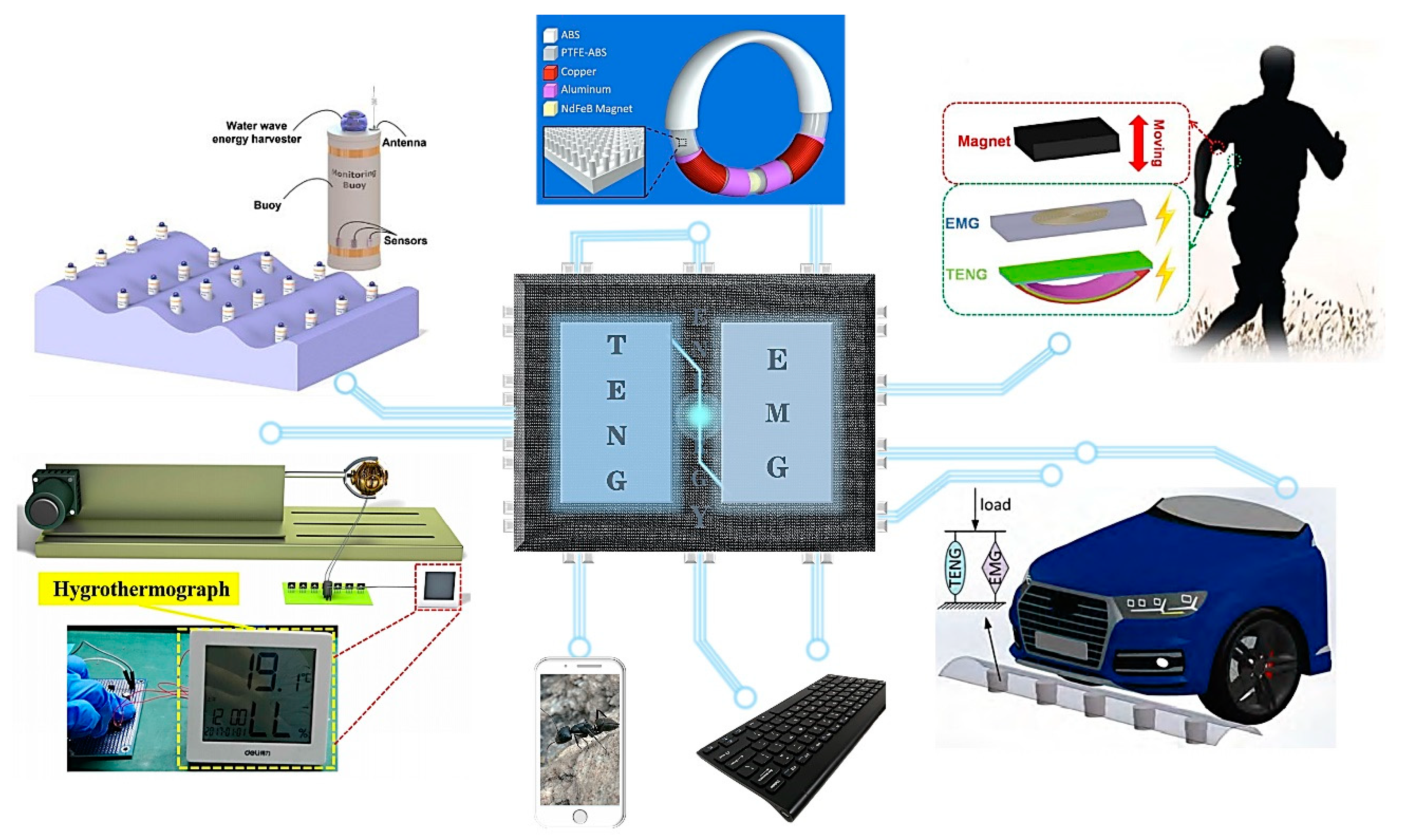
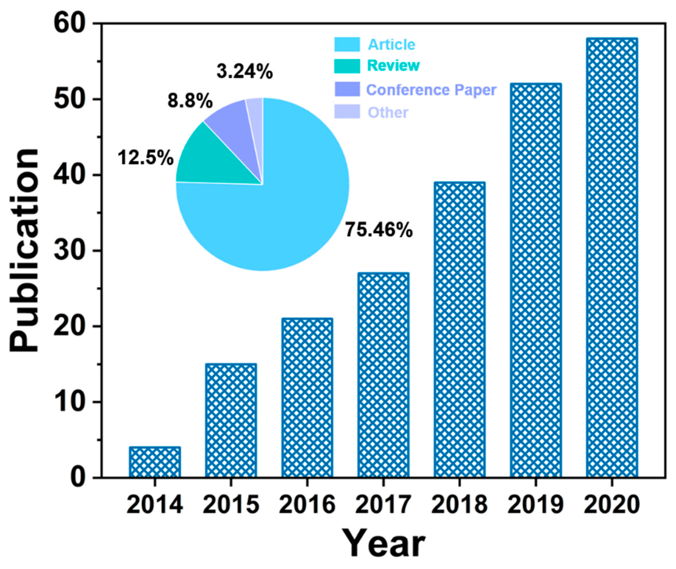
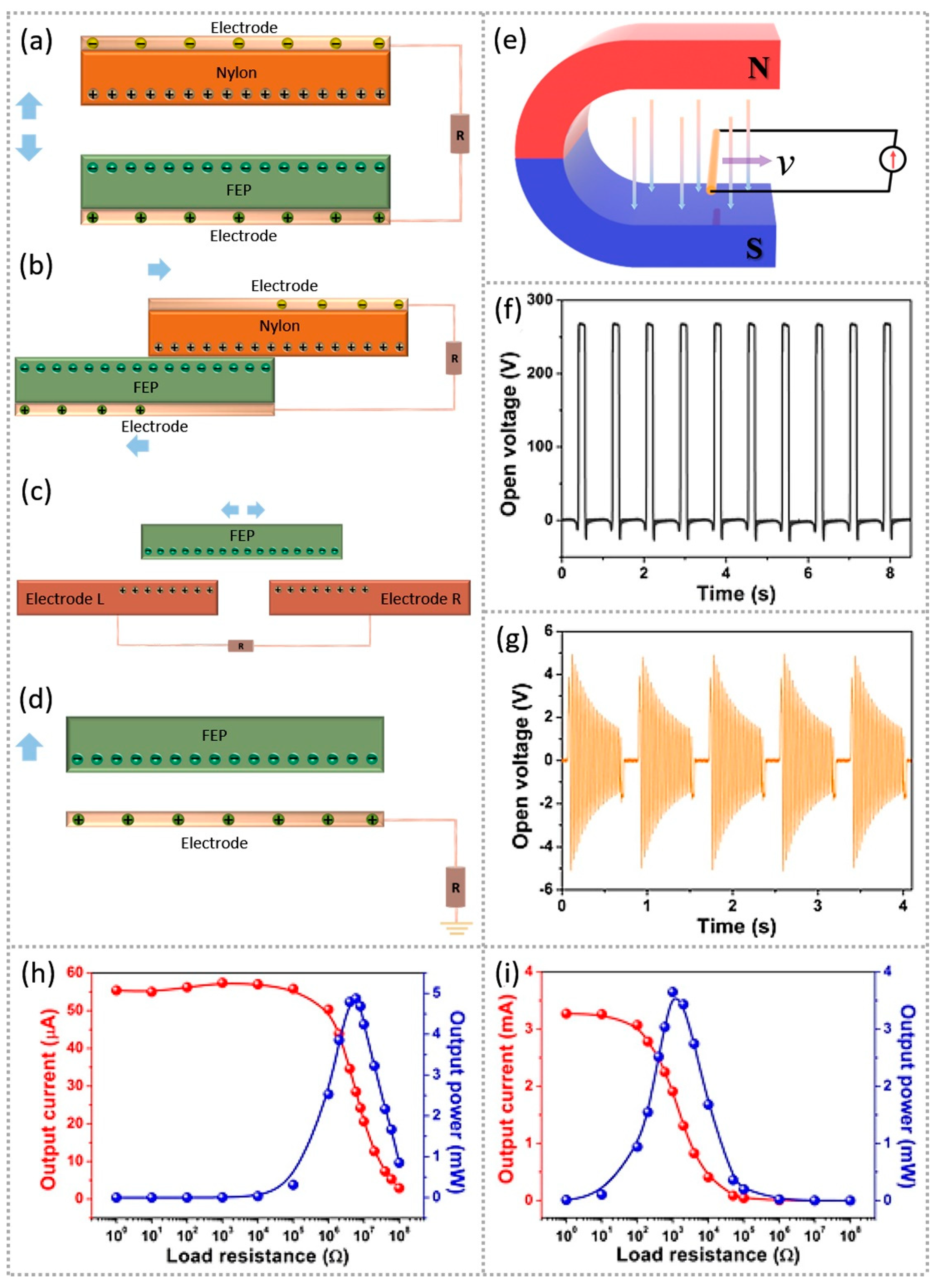
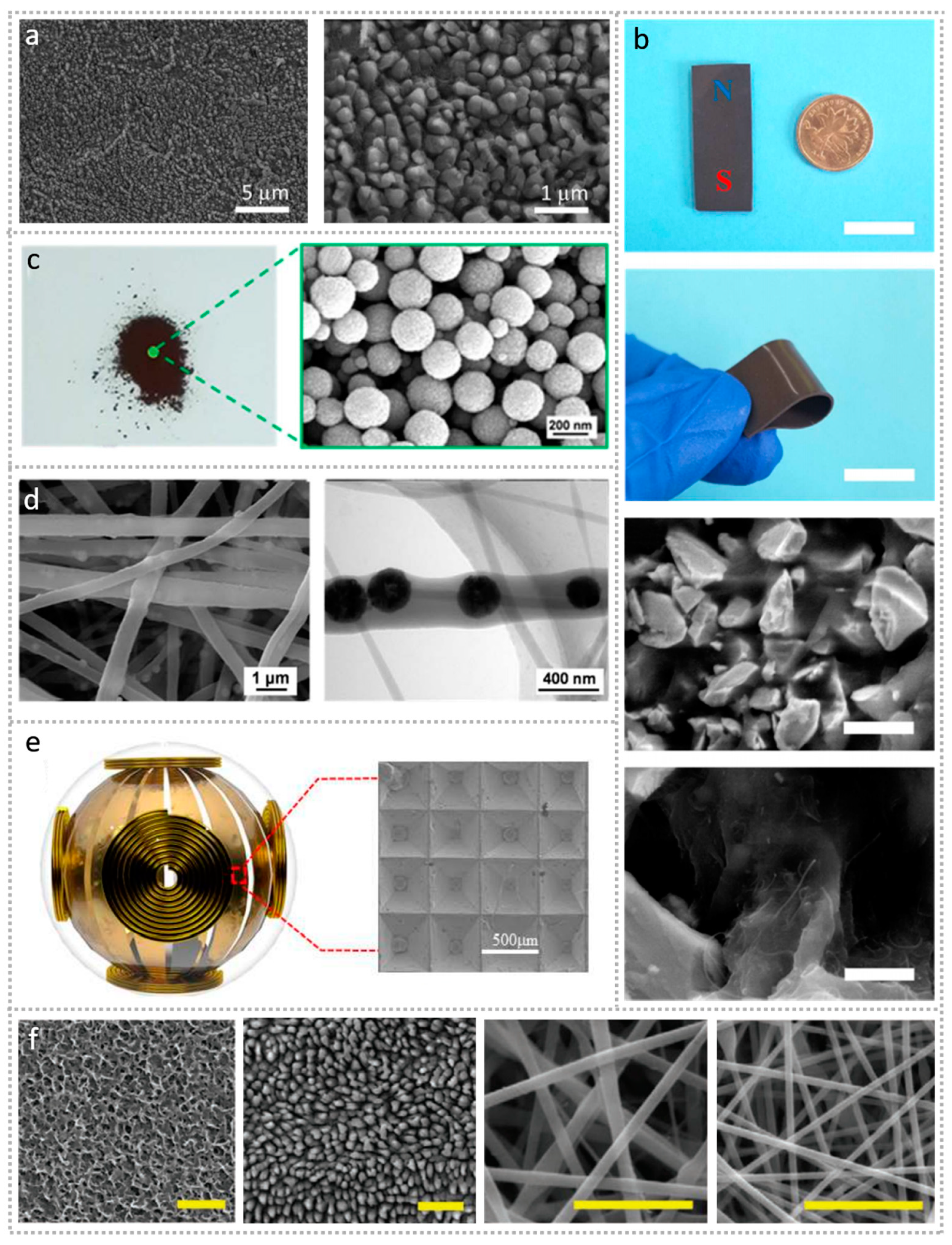
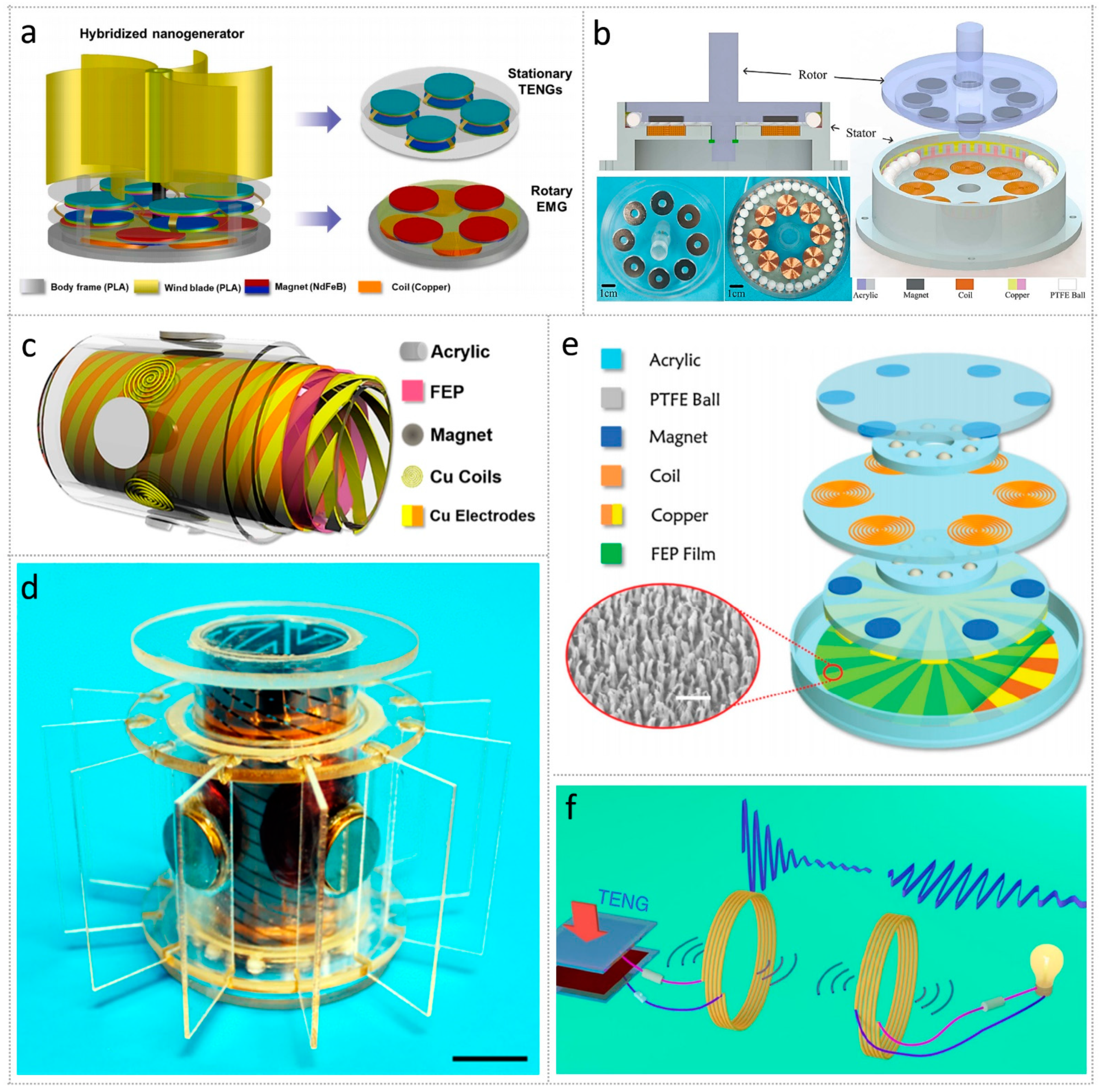
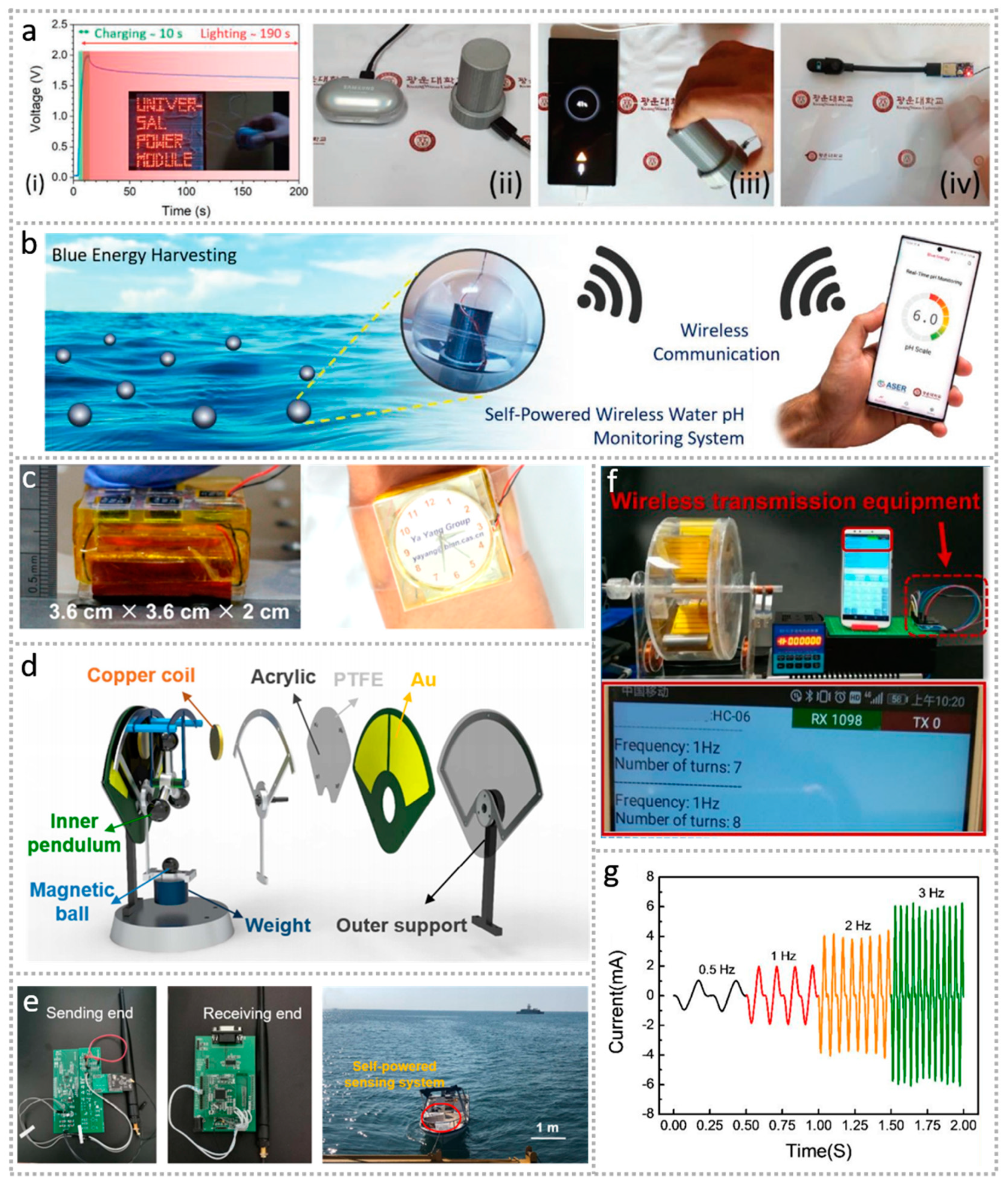
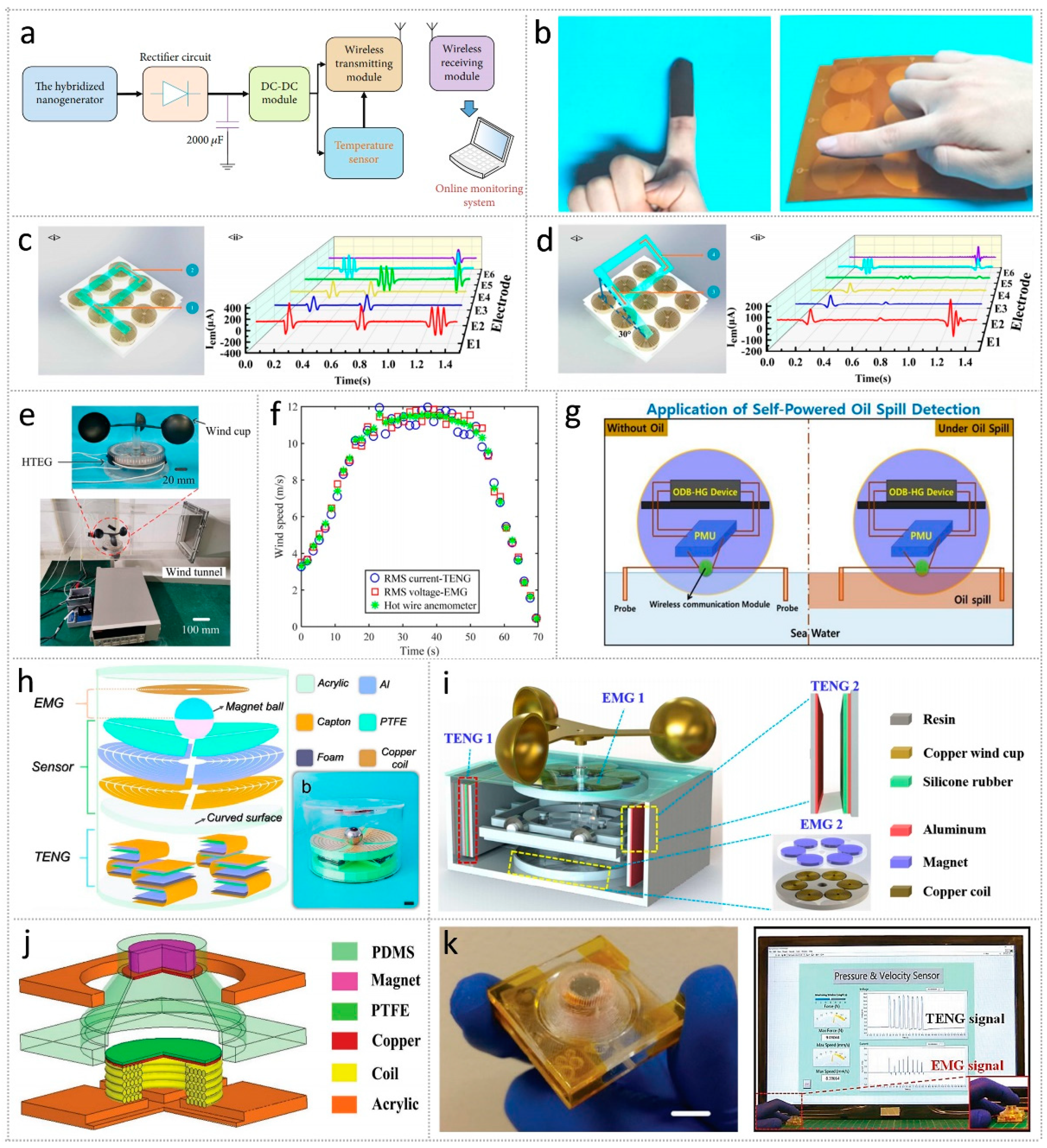
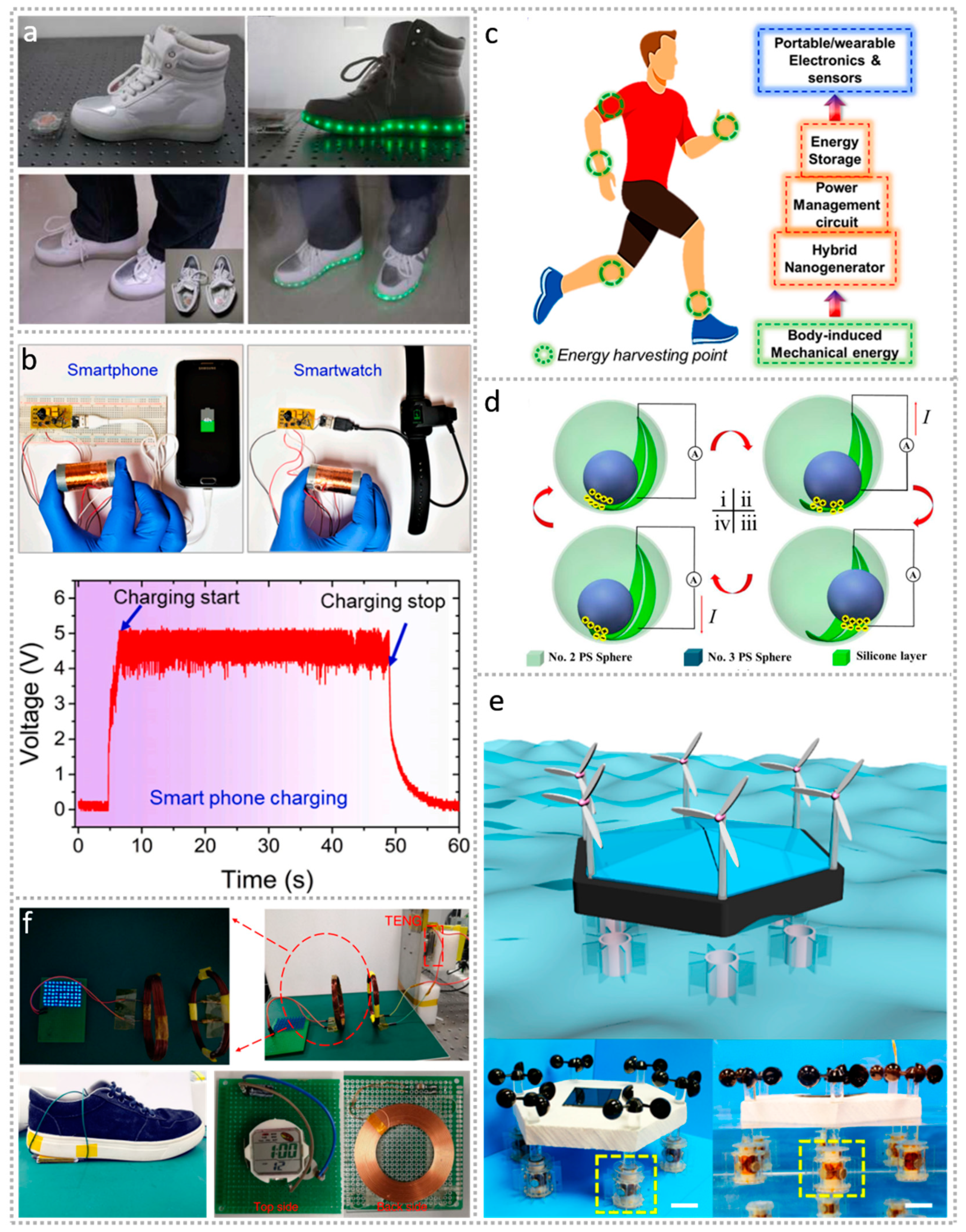
Table 1.
Typical electrical properties of various modes of TENG.
| Modes of TENG | Article | Short-Circuit Current | Open-Circuit Voltage | Peak Power |
|---|---|---|---|---|
| vertical contact–separation mode | Rolling friction contact–separation mode hybrid triboelectric nanogenerator for mechanical energy harvesting and self-powered multifunctional sensors | 1.94 μA/cm2 | 32 V | 0.15 mW/cm2 |
| in-plane sliding mode | High performance floating self-excited sliding triboelectric nanogenerator for micro-mechanical energy harvesting | 76 μA | 470 V | 34.68 mW |
| freestanding-triboelectric-layer mode | Multi-grating triboelectric nanogenerator for harvesting low-frequency ocean wave energy | 60 μA | 140 V | 4.2 mW/m2 |
| single-electrode mode | Water-dielectric single electrode mode triboelectric nanogenerators for ocean wave impact energy harvesting | 5 μA | 7.3 V | 19.12 μW |
Table 2.
The magnitude of input power, output power, energy conversion efficiency, and the volume of EMG-TENG.
Table 2.
The magnitude of input power, output power, energy conversion efficiency, and the volume of EMG-TENG.
| Mechanical Energy Source Types | Article | Maximum Output Power (TENG/EMG) | Hybrized Peak Power | Volume | Energy Conversion Efficiency |
|---|---|---|---|---|---|
| human motions | Appl. Energy 2020, 279, 115799 [119] | 171.13 μW 102.12 mW | 102.29 mW | Ø: ~26 mm h: ~50.5 mm | - |
| winds | ACS Nano 2015, 9, 4553–4562 [95] | 3.5 mW 1.8 mW | 14.6 kW/m3 | 6.7 × 4.5 × 2 cm | |
| wave energy | Research 2021, 2021, 5963293 [93] | 470 μW 523 mW | - | Ø: ~86 mm h: ~80 mm | ~48.48% |
| wind and water-flow energies | Nano Energy 2021, 85, 105974 [99] | 1568 mW kg−1 386 mW kg−1 | 40.65 mW | Ø: ~80 mm h: ~65 mm | - |
Ø is diameter, and h is height.
Publisher’s Note: MDPI stays neutral with regard to jurisdictional claims in published maps and institutional affiliations. |
© 2021 by the authors. Licensee MDPI, Basel, Switzerland. This article is an open access article distributed under the terms and conditions of the Creative Commons Attribution (CC BY) license (https://creativecommons.org/licenses/by/4.0/).
Share and Cite
MDPI and ACS Style
Xu, L.; Hasan, M.A.M.; Wu, H.; Yang, Y. Electromagnetic–Triboelectric Hybridized Nanogenerators. Energies 2021, 14, 6219. https://0-doi-org.brum.beds.ac.uk/10.3390/en14196219
AMA Style
Xu L, Hasan MAM, Wu H, Yang Y. Electromagnetic–Triboelectric Hybridized Nanogenerators. Energies. 2021; 14(19):6219. https://0-doi-org.brum.beds.ac.uk/10.3390/en14196219
Chicago/Turabian StyleXu, Lin, Md Al Mahadi Hasan, Heting Wu, and Ya Yang. 2021. "Electromagnetic–Triboelectric Hybridized Nanogenerators" Energies 14, no. 19: 6219. https://0-doi-org.brum.beds.ac.uk/10.3390/en14196219
Note that from the first issue of 2016, this journal uses article numbers instead of page numbers. See further details here.