
Power Management of a Hybrid Micro-Grid with Photovoltaic Production and Hydrogen Storage
by
 , , , and
Fabrice K/bidi
1,* ,
,
Cédric Damour
1,
Dominique Grondin
1,
Mickaël Hilairet
2,3 and
and
Michel Benne
1 1
Laboratoire d’Energétique, d’Electronique et Procédés (LE2P)—Energy Lab, University of La Réunion, 15, Avenue René Cassin CS 92003, CEDEX 9, 97744 Saint-Denis, France
2
FEMTO-ST Institute, University of Bourgogne Franche-Comte, CNRS, Rue Ernest Thierry Mieg, 90010 Belfort, France
3
FCLAB, University of Bourgogne Franche-Comte, CNRS, Rue Ernest Thierry Mieg, 90010 Belfort, France
*
Author to whom correspondence should be addressed.
Energies 2021, 14(6), 1628; https://0-doi-org.brum.beds.ac.uk/10.3390/en14061628
Submission received: 12 February 2021
/
Revised: 5 March 2021
/
Accepted: 9 March 2021
/
Published: 15 March 2021
(This article belongs to the Special Issue Design, Diagnosis and Control and Social Acceptance of Battery, Solar Cell and Fuel Cell System)
Abstract
:To deal with energy transition due to climate change and a rise in average global temperature, photovoltaic (PV) conversion appears to be a promising technology in sunny regions. However, PV production is directly linked with weather conditions and the day/night cycle, which makes it intermittent and random. Therefore, it makes sense to combine it with Energy Storage Systems (ESS) to ensure long-term energy availability for non-interconnected micro-grids. Among all technological solutions, electrolytic hydrogen produced by renewable energies seems an interesting candidate. In this context, this paper proposes a control strategy dedicated to hydrogen storage integration in micro-grids for a better use of PV production. The objective is to optimize the management of the micro-grid with proton exchange membrane Fuel Cell (FC), alkaline Electrolyzer (El), lithium-ion Batteries Energy Storage System (BESS) and PV, according to the system state and PV production intermittency. First, a control strategy based on a Distributed explicit Model Predictive Control (DeMPC) is developed to define current references for FCs, Els and batteries. Secondly, the performance of the control strategy is validated in simulation and confirmed on a Power-Hardware-in-the-Loop test bench.
1. Introduction
In the past few years, the various actors in the energy field (companies, researchers and public authorities) have highlighted a common interest in electricity generation produced with green energy. A lot of research in the field of renewable energies has made it possible to integrate them into the electrical grid. However, the energy produced by photovoltaic panels and wind turbines depend on climatic conditions, thus leading to high intermittency and random production. As a result, the generation–consumption balance cannot always be ensured, which can impact the electrical grid stability, especially in non-interconnected zones. Therefore, one solution consists of combining them with long-term Energy Storage System (ESS) to deal with the excess or deficit energy [1,2,3]. The most widely used storage systems is batteries. However, these systems have specific drawbacks depending on the technologies [4]. For instance, lead-acid batteries have a high weight and a shorter lifetime than other technologies [5]. Lithium batteries are very expensive and require specific conditions for transport and use due to their chemical composition [5,6]. Among all technological solutions, electrolytic hydrogen produced by renewable energies seems an interesting candidate for a deferred use with Fuel Cell (FC) systems. It has the advantage of a hydrogen production without carbon dioxide emission as well as the decoupling of storage capacity and power. Indeed, battery capacity storage and power depend directly on the number of cells used. In contrast, hydrogen storage capacity depends on the considered technology (e.g., solid, liquid or gaseous), while power generation depends on FC itself. Combining hydrogen and batteries storage can take advantage of both technology: high power density for the batteries and high energy density from the hydrogen system [7]. Nevertheless, FC and Electrolyzer (El) can suffer from severe degradation if their operating conditions are not respected, e.g., fast variations of the current, high and low operating powers, and so on [8,9,10,11]. In this context, ensuring reliable and accurate power response of all the components while respecting proper operating conditions remain a challenge.
Hydrogen storage systems are widely studied for transport applications. In Hilairet et al. [12], authors use the passivity methodology to control a FC and super-capacitor (SC) hybrid system. The controller computes the reference currents for each unit to regulate the Direct Current (DC)bus voltage and ensure good operating conditions of the FC. Simulation and experimental results show good performance. A Mixed Droop Control Strategy to allocate power to the FC and the SCs considering current dynamic constraints is developed in Chen et al. [13]. The control strategy is validated in simulation and in a Hardware-in-the-Loop real-time simulation platform. An Extremum Seeking method is proposed in Zhou et al. [14] to control an FC and battery hybrid system for electrical vehicles. The effectiveness of the control is validated with experimental results.
Hydrogen is also under consideration for micro-grids. In Sun et al. [15], authors propose two basic coordinated control strategies for a hybrid energy system composed of batteries, wind turbines, FCs and photovoltaic panels (PVs) connected to the grid. The performance of the proposed control is assessed in simulation. The authors in Sharma et al. [16] propose a conditional statements power management algorithm with three operation modes in function of the difference between PV and load powers. The hybrid system is composed of FC, batteries and PV. The algorithm compute s the reference currents for each unit of the micro-grid while taking into account constraints on current dynamics of each element. The authors demonstrate the effectiveness of the strategy using simulation and experimentation results. In the same context, in Mane et al. [17] the authors propose a flowchart with conditional statement functions of PV, load, and FC powers, as well as the battery state of charge. Simulation results show the effectiveness of the power management strategy. A multiple-modes power distribution strategy is used in Li et al. [18] for a DC micro-grid composed of batteries, FC, wind turbines, and PV, where the FC power increases in steps of 100 W depending on renewable source availability and load power demand. The strategy is experimentally validated. In Mane et al. [19], the authors proposed a non-linear controller based on Lure–Lyapunov formulation for a hybrid system composed of FC and SCs. Experimental results are provided. Even if several studies have been conducted regarding the integration of hydrogen vector in different systems, few studies take explicitly into account all the component constraints of the micro-grid in the controller.
The main drawback of these approaches is that they do not allow explicit integration of the minimum and maximum current constraints as well as the maximum current dynamics of the FC and the electrolyzer into the controller without deteriorating the stability of the closed-loop system. In this context, in Mariethoz et al. [20] the authors use a Model Predictive Control (MPC) that explicitly incorporates constraints into the controller design. MPC has the advantage of being able to easily manage multi-variable systems and their constraints. In recent years, the existence of mathematical models of power electronics has made it possible to use MPC in electrical systems. However, the computational load makes the implementation difficult with a low time-step. To overcome this issue, the optimization problem can be solved offline by multi-parametric programming to reduce the implementation to a few computations and a look-up table. This approach reduces the computational cost and allows the MPC to be used with a low time-step [21].
This study concerns the integration of hydrogen produced by decarbonated energy from PV panels for a better use of renewable energies in an islanded micro-grid to supply public buildings [22], such as the SAGES project in Mafate, La Réunion. The main issues preventing the use of hydrogen as an energy vector in micro-grids is the low reliability and high cost of this technology due to the brittleness and complex usage. However, an adapted controller allows the respecting of the constraints on the system and to improve the remaining useful life of the components. In this context, a Distributed explicit Model Predictive Control (DeMPC) has been applied to control a complex hydrogen-energy system composed of a FC/El associated with long-term hydrogen storage, batteries for short-term storage and PV panels as main power source. The Power Management System (PMS) explicitly takes into account each unit operating constraints (maximum/minimum current, response time, etc.) [20]. Moreover, it is possible to take into account the architecture of the system in real time when the power electronic topology is reconfigured in case of failure [23] or units (FC or El) commitment in case of power partitioning, as well as to change the tuning parameters according to the FC/El state of health based on diagnosis/prognosis tools [24]. The performance of the PMS is assessed experimentally on a Power-Hardware-In-the-Loop (PHIL) test bench to confirm the effectiveness of the proposition. The main purpose of this work is the integration of the PMS with the DeMPC controller to define the reference currents of the elements in a complex system. The objective of the DeMPC is the control of the DC bus voltage and the State of Charge (SoC) of the battery to ensure the stability of the micro-grid without damaging the FC and the electrolyzer. The principal contributions of this work are:
- The implementation of an DeMPC-based control strategy that explicitly takes into account the constraints of the elements in complex systems such as a micro-grid with a hydrogen system,
- The performance of tests of the control strategy on a PHIL test bench to show the applicability of the strategy on real systems.
2. Power Management System Design and Simulation
2.1. Micro-Grid Modeling
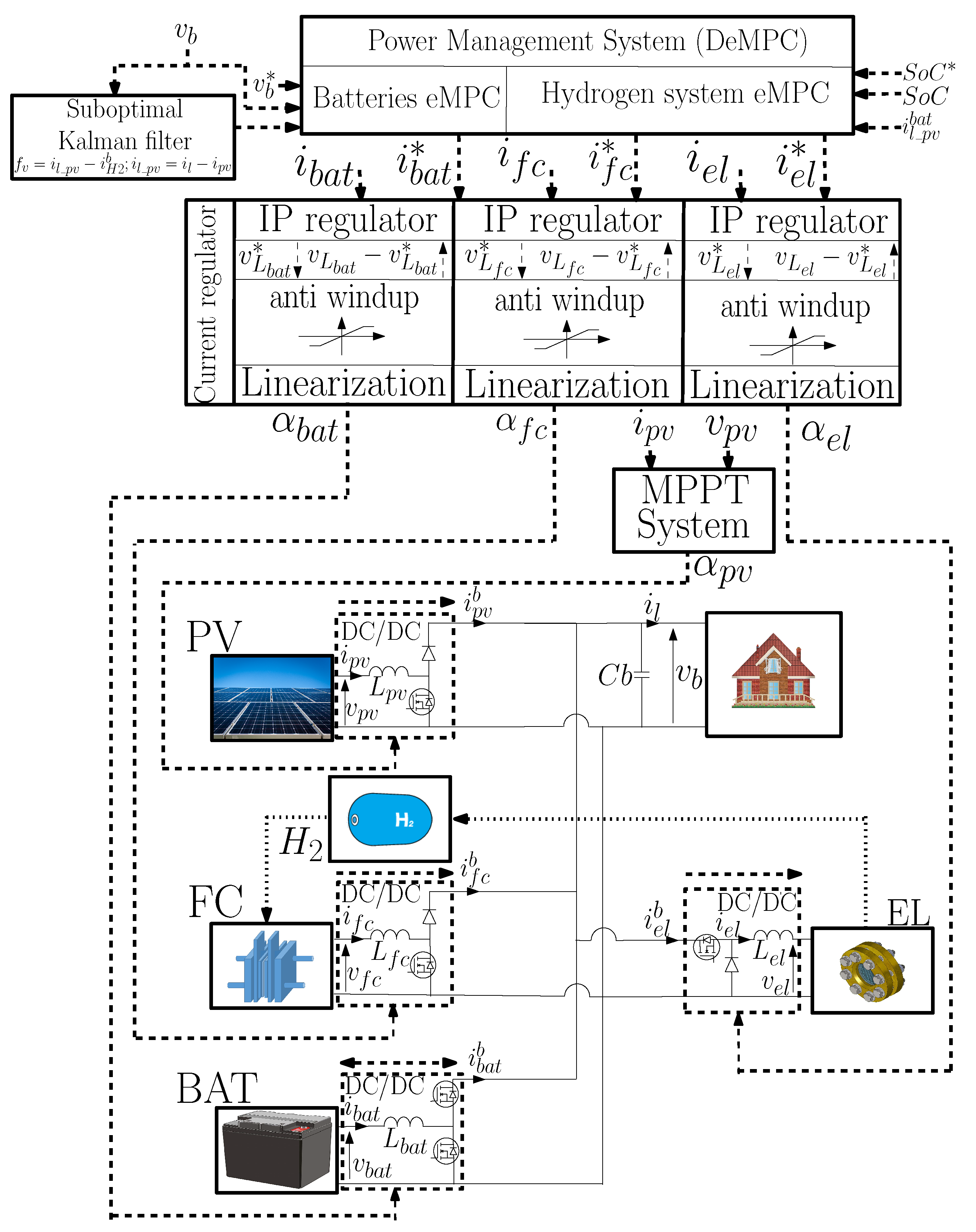
The micro-grid studied in this paper is composed of Batteries Energy Storage System (BESS), PV, a FC stack and an El. Each element is connected to a DC/DC converter as shown in Figure 1.
2.1.1. Photovoltaic Model
2.1.2. Battery Model
2.1.3. Fuel Cell and Electrolyzer Models
The FC voltage is computed based on a 5-order polynomial equation of the FC current obtained from experimental tests on a 1.2 kW, 46 A and 26 V Nexa Ballard FC [12]. In the same way, the El voltage depends on the El current based on [29]. The equation parameters have been fitted based on experimental results of an H2 IGen 300/1/25 manufactured by Vandenborre (currently, Hydrogenics, Mississauga, Canada) 5 kW, 43 V and 120 A Alkaline Electrolyzer.
2.1.4. Overall System Model
2.2. Power Management System Design
The PMS is based on a DeMPC that explicitly takes into account each component specific operating conditions and constraints.
First, the PVs has its proper Maximum Power Point Tracking (MPPT) command [30]. Secondly, the PMS is composed of an outer loop composed of two explicit Model Predictive Controls (eMPC), one for the BESS and another for the hydrogen system composed of the FC, El and hydrogen storage. The inner current control loops with Integral-Proportional (IP) controllers are used and tune so that the inner loops are fast compared to the dynamic of the outer loops based on the DeMPC. Therefore, based on the singular perturbation theorem [31], the system equations for the design of the outer loops (DeMPC) can be simplified as follows [32]:
Here, all currents are supposed to be properly regulated by the inner current control loops. It follows that , and are supposed perfectly regulated and are the inputs of the reduced order system (8) and (9).
2.2.1. BESS eMPC
The BESS eMPC computes the BESS current reference that controls the DC bus voltage. In the system, batteries consume the excess energy and restore it in case of an energy deficit when the other units cannot react. The PV and load currents ( and ) are considered to be perturbations in the eMPC and the difference between these two currents is called for simplification.
- System equations
The battery eMPC is based on the linearized and discretized Equation (8) as follows.
with:
where is the state variable, is the control input and is considered to be a perturbation. is the eMPC sampling time fixed at 500 μs. At the end, the battery reference current value is sent to the battery current controller based on the inversion of Equation (15):
- System constraints
The only constraints taken into account for batteries are the minimum and maximum currents expressed in the DC bus point of view as follows:
- Objective function
The objective function is written in the quadratic form. Its main role is to minimize the error between the DC bus voltage reference and its measured value at each time-step over the prediction horizon (the first term of the objective function in Equation (21). Also, it minimizes the battery current seeing by the bus to stabilize it (second term of the objective function in Equation (21). The objective function is written as:
is the prediction horizon, is the weight of the first objective function criterion and its value is fixed to respect the reference tracking while ensuring the battery current stability. If is too high, then there may be significant variations of between and . Its value is set to get as close as possible to the reference value while ensuring a minimum fluctuation in .
2.2.2. Hydrogen System eMPC
The () system is composed of the FC and the El that does not work at the same time. Its current is considered to be the sum of the FC current and the El current Equation (23) computed by the eMPC to maintain the battery SoC at a define value. The El current is negative, and the FC current is positive.
- System equations
The hydrogen system eMPC is based on the linearization and discretization of Equation (9) where is the input control. As with the BESS eMPC, the PV and load currents are merged in one variable noted .
with:
where is the state variable, is the control input variable and is considered to be a perturbation. is the eMPC sampling time fixed at 2 ms. FC and El current reference values are sent to the FC and El current controllers based on the inversion of Equations (26) and (28) respectively:
- System constraints
Due to the design and physical phenomena into FC and El, specific operating conditions (response time, maximum power, etc.) need to be respected to avoid premature ageing. The eMPC needs to take into account the maximum and minimum currents (31) and the maximum and minimum current ramp rates (32). These parameters need to be written linearly to be integrated in the eMPC Equations (33)–(35):
- Objective function
Like the BESS eMPC, the objective function is written in the quadratic form. The main criterion is to ensure the reference tracking of the (first part of the objective function). In the second part, the variation is minimized to limit the charge and discharge of the battery. The third criterion minimizes the difference between the system current seeing by the battery ( system current supplied to the battery) and the DC bus current seeing by batteries (current from batteries supplied to the DC bus). This is to bring the battery current to zero and to maintain the battery when the is close to its reference.
- Parameters setting
The FC and El current references depend on the system current reference value . If , it is assigned to the FC, and . Vice versa if it assigned to the El, and . The condition statement is summarized as shown on the Algorithm 1.
 |
The maximum and minimum system currents are set to , = .
2.2.3. Sub-Optimal Kalman Filter
Due to the current sensor cost and the distance between the load and the generator in a micro-grid, the load current is considered to be an unmeasured variable to reduce the number of sensors and improve the reliability. Here, it is estimated with a sub-optimal Kalman filter based on the measurement of the DC bus voltage.
where is considered to be an unknown input called fv, which is assumed to be nearly constant during one sampling period, i.e., . It follows that fv is estimated based on this linear state space model:
is determined with and the estimated value fv. can be used in Equation (10) and in (22) and (36).
2.2.4. Design Tools
2.3. Simulation Results
The system represented in Figure 1 is tested with the DeMPC to validate the control strategy before experimental tests. The system is simulated with a step time equal to 50 μs. The reference is equal to the initial (50%) and the DC bus voltage reference is set to 70 V.
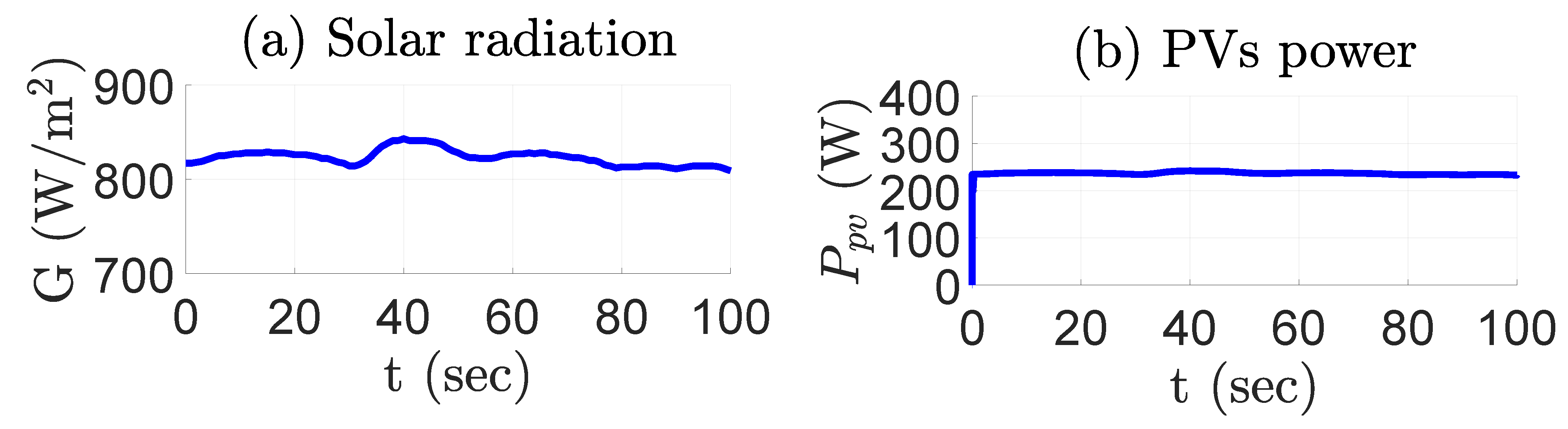
Figure 2 shows the PV system output power according to the solar radiation and the ambient air temperature (considered to be constant at 30 C). The solar radiation data are based on a measurement campaign with a sampling step of 1s carried out on the UFR science building at the Moufia site of the University of La Réunion. Result of the PV output power simulation is consistent with the expected results.
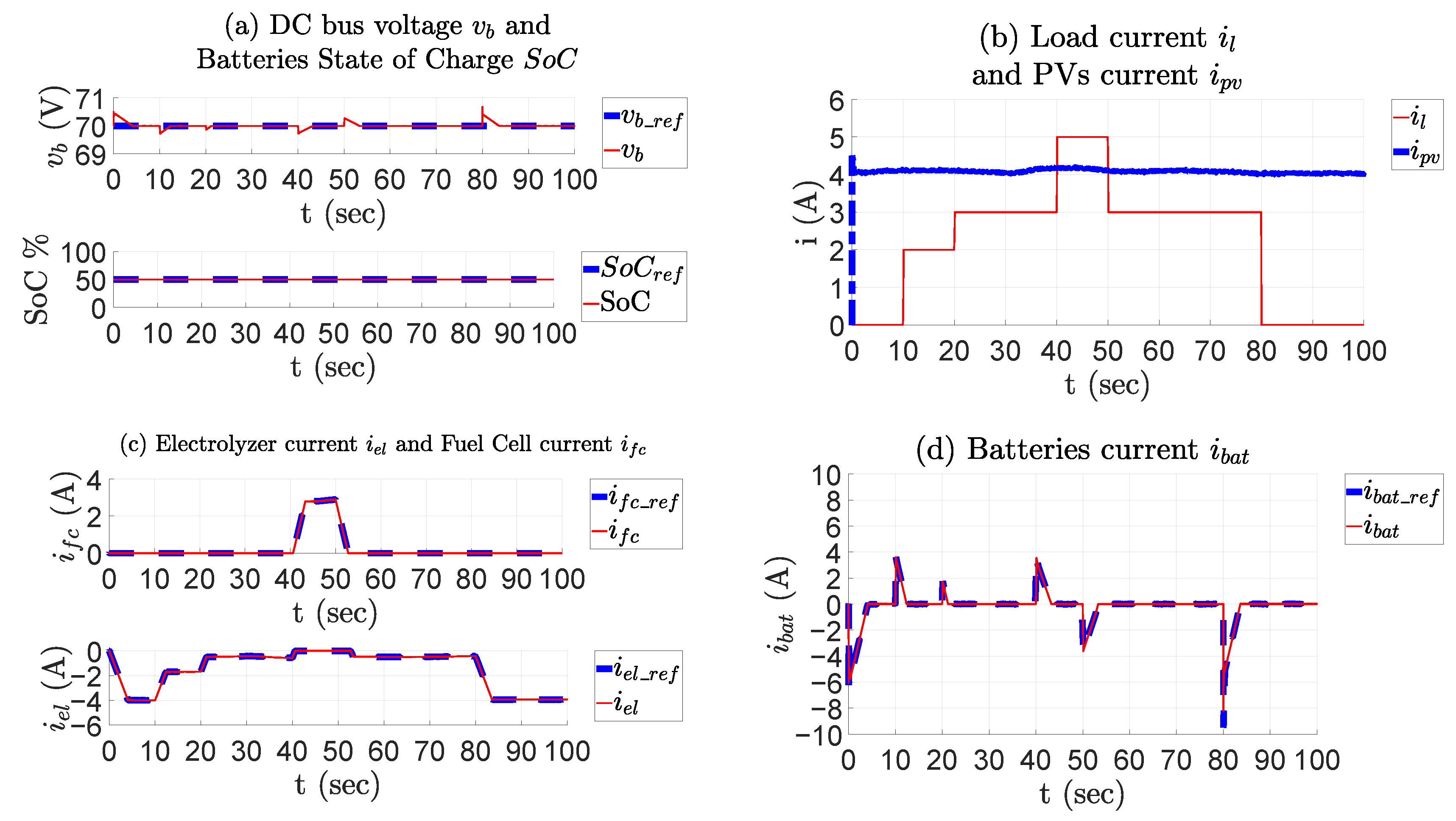
Figure 3 represents the simulation results of the DeMPC and shows that the DC bus voltage reference tracking is correctly performed (between −0.4% and +0.95% of the reference). Also, the FC and El currents maximum ramp are respected, and batteries react to the high variation of the load or the PV production. The variation is insignificant due to the short simulation time. Between 0 to 40 s and 50 to 100 s, the PV power is higher than the load power. In this duration, the El is running (sub-zero current). At 0, 50 and 80 s respectively, the DC bus voltage increases due to the surplus production. The battery absorbs excess production while the El current increases progressively in respect to the ramp rate current to bring back the battery current to zero. At 10, 20 and 40 s respectively, the battery provides the load when the load power increase and the El current decrease progressively in respect with the ramp rate current. This is to bring back the battery current to zero. In the opposite case, between 40 and 50 s, the PV power is lower than the load power and at 40 s the DC bus voltage decrease due to the production deficit. At 40 s, the battery provides the load while the FC current increases progressively in respect to the ramp rate current to bring back the battery current to 0. At 50 s, the battery absorbs the FC current to let it decrease progressively and bring back the battery current to 0. At 80 s, a higher current peak can be observed. This peak is due to the higher difference between the PV current and the load current and due to the step time choose for the battery eMPC [32]. Simulation shows that the proposed strategy give s excellent results in terms of DC bus voltage regulation while taking into account elements operation constraints.
Compared to the simulation results in [13] with a mixed droop control strategy, the error on the DC bus voltage induced by a load current variation is lower and the FC, battery, and electrolyzer current variation is more linear.
3. Experimentation
3.1. Procedure
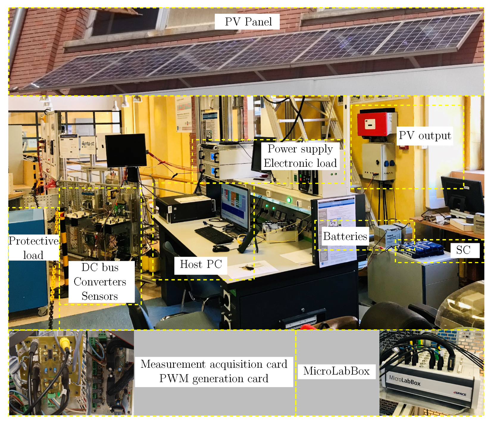
Experimental tests were carried out on a Power Hardware-In-the-Loop (PHIL) test bench shown in Figure 4. The parameters of the test bench system are available in Appendix A. It is composed of three 12 V AGM batteries and two 165 W PV modules with their converters. As a first step, to reduce the test bench cost and complexity, the fuel cell power output (FC and converter) is emulated with a programmable supply (reference: EA-PSI 9080-340). For the same reason, the power load requirement and the electrolyzer power load (El and converter) are emulated with an electronic load (reference: EA-ELR 9080-510). The controller runs on a dSPACE DS1202 board and the measurements are made with a DS1302 board.
3.2. Results
At the experimentation beginning, the load current is null, and the PV is connected to the system. The load cycle begins when all currents are stabilized. As for the simulation, the DC bus voltage reference tracking is correctly performed (between −2.43% and +0.62% of the DC bus voltage reference, Cf. Figure 5). The experimental results show the control strategy ability to control a real system. The results are consistent with those expected after the simulation. The maximum FC and El currents ramp rate are respected. From 0 to approximately 30 s and approximately 85 to 100 s, the PV power is higher than the load power. In this duration, the El is running (sub-zero current). At 0 and between 80 and 90 s, the DC bus voltage increased due to the surplus production. The battery absorbs excess production while the El current increases progressively in respect to the ramp rate current to bring back the battery current to zero. Between 20 and 30 s, the battery provides the load when the load power increase and the El current decrease progressively in respect with the ramp rate current. This is to bring back the battery current to zero. In the opposite case, between 30 and 90 s, the PV power is lower than the load power and at 40s the DC bus voltage and decrease due to the production deficit. At 30 s and 50 s, the battery provides the load while the FC current increase progressively in respect to the ramp rate current to bring back the battery current to 0. At 60 s and between 80 and 90 s, the battery absorbs the FC current to let it decrease progressively. The higher oscillation that can be observed in the DC bus voltage and the battery current compared to the simulation is due to the order reduction made for the system equations.
4. Discussion
Compared to the initial work in [20], PV panels and an electrolyzer have been added to the system to complete the work and test the strategy for a micro-grid configuration. The experimental results show the ability of the proposed strategy to manage an H2 system with hydrogen storage, hydrogen production from the electrolyzer and electricity production from the FC. Moreover, the fluctuations of the battery current are lower than those of the SC current in the initial work. Finally, compared to other control strategies in the literature, the use of eMPC does not result in any slowdown near the reference, such as regular controllers where the dynamic is governed by first- or second-order differential equations [13,16,32]. With the presented strategy, the current evolution is more rectilinear when the PV production or load consumption changes. The constraints on the current ramp rates are strictly respected for the FC and the electrolyzer to improve the remaining useful time. This feature allows the chemical and physical characteristics of the FC and the electrolyzer to be taken into account to use them more effectively. Moreover, the eMPC can be reconfigured on-line to take into account a modification of the power source topology in case of failure [23] or units (FC or El) commitment in case of power partitioning. In addition to this, on-line tuning parameters are also possible based on FC/El state of health founded on diagnosis/prognosis indicators [24].
5. Conclusions
In this paper, a Power Management System architecture for a micro-grid composed of proton exchange membrane fuel cell, alkaline electrolyzer, li-ion batteries and photovoltaic panels has been designed. Based on distributed explicit model predictive control, the Power Management System defines current reference of the fuel cell, the electrolyzer and the batteries while explicitly taking into account all component operating conditions and constraints. The effectiveness of the control strategy is validated in simulation and on a Power Hardware-In-the-Loop test bench. The average error in the DC bus voltage in steady state is about 0.02% in simulation and the experimental results confirm this performance. The ability of the explicit model predictive control to ensure voltage regulation in the presence of disturbances is therefore confirmed. The respect of the constraints of the components according to the operating conditions (ramp current, etc.) is also confirmed.
Many perspectives of this work are considered. We can cite the integration of an Energy Management System (EMS) combined with the proposed PMS developed in this work. The main objective of the EMS is the optimization of the engagement plan of the FC and the electrolyzer to take into account operating constraints and external conditions: e.g., minimum/maximum operating currents, minimum operating time, load and PV power forecasting.
Author Contributions
Conceptualization, F.K., C.D., D.G., M.H., M.B.; methodology, F.K., C.D., D.G., M.H., M.B.; software, F.K., C.D., M.H.; validation, F.K., C.D., M.H.; formal analysis, C.D., M.H., F.K.; resources, M.H., D.G., M.B.; writing—original draft preparation, F.K., C.D., D.G., M.H., M.B.; writing—review and editing, F.K., C.D., D.G., M.H., M.B; supervision, M.H., M.B.; project administration, M.H., M.B.; funding acquisition, M.H., M.B. All authors have read and agreed to the published version of the manuscript.
Funding
This research work was funded by the ERDF (“European Regional Development Fund”) and the Region Council of La Réunion.
Institutional Review Board Statement
Not applicable.
Informed Consent Statement
Not applicable.
Data Availability Statement
Not applicable.
Conflicts of Interest
The authors declare no conflict of interest.
Appendix A. System Parameters
| Batteries | |||
| Nominal capacity | 18 Ah | Max charging current | 15 A |
| Nominal voltage | 36V | Max discharging current | 15 A |
| PVs (1000 ) | |||
| Power at Pmax | 165 W | 1 | |
| Voltage at Pmax | 68.8 V | Current at Pmax | 4.8 A |
| Electrolyzer | Fuel Cell | ||
| max production | 1 | Power at Pmax | 1200 W |
| Nominal voltage | 86 V | Nominal voltage | 26 V |
| Nominal current | 120 A | Nominal current | 46 A |
| DC/DC converter | |||
| 100 mH | 100 mH | ||
| 1 mH | 1 mH | ||
| DC bus | |||
| 19.8 μ | DC bus voltage reference | 70 V | |
| MPC | |||
| 500 μ | 15 × 10 | ||
| 2 ms | 5 × 10 | ||
| 5 | 50 | ||
| 3 | |||
References
- Michaelson, D.; Mahmood, H.; Jiang, J. A Predictive Energy Management System Using Pre-Emptive Load Shedding for Islanded Photovoltaic Microgrids. IEEE Trans. Ind. Electron. 2017, 64, 5440–5448. [Google Scholar] [CrossRef]
- Sechilariu, M.; Wang, B.; Locment, F. Building Integrated Photovoltaic System With Energy Storage and Smart Grid Communication. IEEE Trans. Ind. Electron. 2013, 60, 1607–1618. [Google Scholar] [CrossRef]
- Chau, T.K.; Yu, S.S.; Fernando, T.; Iu, H.H.C. Demand-Side Regulation Provision From Industrial Loads Integrated With Solar PV Panels and Energy Storage System for Ancillary Services. IEEE Trans. Ind. Inform. 2018, 14, 5038–5049. [Google Scholar] [CrossRef]
- Slaughter, A. Electricity Storage: Technologies, Impacts, and Prospects. 2015. Available online: https://www2.deloitte.com/content/dam/Deloitte/us/Documents/energy-resources/us-er-electric-storage-paper.pdf (accessed on 12 April 2017).
- Bukhari, S.M.A.S.; Maqsood, J.; Baig, M.Q.; Ashraf, S.; Khan, T.A. Comparison of Characteristics—Lead Acid, Nickel Based, Lead Crystal and Lithium Based Batteries. In Proceedings of the 17th UKSim-AMSS IEEE International Conference on Modelling and Simulation, Cambridge, UK, 25–27 March 2015; pp. 444–450. [Google Scholar] [CrossRef]
- Battke, B.; Schmidt, T.S.; Grosspietsch, D.; Hoffmann, V.H. A Review and Probabilistic Model of Lifecycle Costs of Stationary Batteries in Multiple Applications. Renew. Sustain. Energy Rev. 2013, 25, 240–250. [Google Scholar] [CrossRef]
- Zhang, Y.; Lundblad, A.; Campana, P.E.; Yan, J. Comparative Study of Battery Storage and Hydrogen Storage to Increase Photovoltaic Self-Sufficiency in a Residential Building of Sweden. Energy Procedia 2016, 103, 268–273. [Google Scholar] [CrossRef]
- Zhang, T.; Wang, P.; Chen, H.; Pei, P. A Review of Automotive Proton Exchange Membrane Fuel Cell Degradation under Start-Stop Operating Condition. Appl. Energy 2018, 223, 249–262. [Google Scholar] [CrossRef]
- Fletcher, T.; Thring, R.; Watkinson, M. An Energy Management Strategy to Concurrently Optimise Fuel Consumption & PEM Fuel Cell Lifetime in a Hybrid Vehicle. Int. J. Hydrog. Energy 2016, 41, 21503–21515. [Google Scholar] [CrossRef] [Green Version]
- Godula-Jopek, A.; Stolten, D. Hydrogen Production: By Electrolysis; Agata Godula-Jopek; Wiley VCH: Weinheim, Germany, 2015. [Google Scholar]
- Carmo, M.; Fritz, D.L.; Mergel, J.; Stolten, D. A Comprehensive Review on PEM Water Electrolysis. Int. J. Hydrogen Energy 2013, 38, 4901–4934. [Google Scholar] [CrossRef]
- Hilairet, M.; Ghanes, M.; Béthoux, O.; Tanasa, V.; Barbot, J.P.; Normand-Cyrot, D. A Passivity—Based Controller for Coordination of Converters in a Fuel Cell System. Control. Eng. Pract. 2013, 21, 1097–1109. [Google Scholar] [CrossRef] [Green Version]
- Chen, J.; Song, Q. A Decentralized Dynamic Load Power Allocation Strategy for Fuel Cell/Supercapacitor-Based APU of Large More Electric Vehicles. IEEE Trans. Ind. Electron. 2019, 66, 865–875. [Google Scholar] [CrossRef]
- Zhou, D.; Al-Durra, A.; Matraji, I.; Ravey, A.; Gao, F. Online Energy Management Strategy of Fuel Cell Hybrid Electric Vehicles: A Fractional-Order Extremum Seeking Method. IEEE Trans. Ind. Electron. 2018, 65, 6787–6799. [Google Scholar] [CrossRef]
- Sun, L.; Wu, G.; Xue, Y.; Shen, J.; Li, D.; Lee, K.Y. Coordinated Control Strategies for Fuel Cell Power Plant in a Microgrid. IEEE Trans. Energy Convers. 2018, 33, 1–9. [Google Scholar] [CrossRef]
- Sharma, R.K.; Mishra, S. Dynamic Power Management and Control of a PV PEM Fuel-Cell-Based Standalone Ac/Dc Microgrid Using Hybrid Energy Storage. IEEE Trans. Ind. Appl. 2018, 54, 526–538. [Google Scholar] [CrossRef]
- Mane, S.; Kadam, P.; Lahoti, G.; Kazi, F.; Singh, N.M. Optimal Load Balancing Strategy for Hybrid Energy Management System in DC Microgrid with PV, Fuel Cell and Battery Storage. In Proceedings of the 2016 IEEE International Conference on Renewable Energy Research and Applications (ICRERA), Birmingham, UK, 20–23 November 2016; pp. 851–856. [Google Scholar] [CrossRef]
- Li, C.; Lin, C.; Chang-Chien, L. Energy Management Strategy for Renewable Backup Supply. In Proceedings of the 2017 IEEE Second International Conference on DC Microgrids (ICDCM), Bamberg, Germany, 27–29 June 2017; pp. 577–581. [Google Scholar] [CrossRef]
- Mane, S.; Mejari, M.; Kazi, F.; Singh, N. Improving Lifetime of Fuel Cell in Hybrid Energy Management System by Lure–Lyapunov-Based Control Formulation. IEEE Trans. Ind. Electron. 2017, 64, 6671–6679. [Google Scholar] [CrossRef]
- Mariethoz, S.; Bethoux, O.; Hilairet, M. A Distributed Model Predictive Control Scheme for Reducing Consumption of Hybrid Fuel Cell Systems. In Proceedings of the IECON 2012—38th Annual Conference on IEEE Industrial Electronics Society, Montreal, QC, Canada, 25–28 October 2012. [Google Scholar] [CrossRef]
- Vazquez, S.; Leon, J.I.; Franquelo, L.G.; Rodriguez, J.; Young, H.A.; Marquez, A.; Zanchetta, P. Model Predictive Control: A Review of Its Applications in Power Electronics. IEEE Ind. Electron. Mag. 2014, 8, 16–31. [Google Scholar] [CrossRef]
- Directory of Projects in France, Cirque de Mafate (Reunion Island) (in French: Annuaire Des Projets En France, Cirque de Mafate (La Réunion). Available online: http://www.smartgrids-cre.fr/index.php?p=cirquedemafate (accessed on 20 April 2020).
- K/bidi, F.; Damour, C.; Grondin, D.; Hilairet, M.; Benne, M. Model Predictive Control for Micro Grid Stabilisation in Case of Loss of Units. In Proceedings of the 2019 IEEE 58th Conference on Decision and Control (CDC), Nice, France, 11–13 December 2019; pp. 3266–3271. [Google Scholar] [CrossRef]
- Kong, S.; Bressel, M.; Hilairet, M.; Roche, R. Advanced Passivity-Based, Aging-Tolerant Control for a Fuel Cell/Super-Capacitor Hybrid System. Control. Eng. Pract. 2020, 105, 104636. [Google Scholar] [CrossRef]
- Tian, H.; Mancilla-David, F.; Ellis, K.; Muljadi, E.; Jenkins, P. A Cell-to-Module-to-Array Detailed Model for Photovoltaic Panels. Solar Energy 2012, 86, 2695–2706. [Google Scholar] [CrossRef]
- Rasool, F.; Drieberg, M.; Badruddin, N.; Mahinder Singh, B.S. PV Panel Modeling with Improved Parameter Extraction Technique. Sol. Energy 2017, 153, 519–530. [Google Scholar] [CrossRef]
- TENESOL Module TE1300-1700. Available online: http://www.cmacpower.co.za/te-1300-te-1700-tenesol-brochure.htm (accessed on 22 January 2018).
- Chen, M.; Rincon-Mora, G. Accurate Electrical Battery Model Capable of Predicting Runtime and I–V Performance. IEEE Trans. Energy Convers. 2006, 21, 504–511. [Google Scholar] [CrossRef]
- Dieguez, P.; Ursua, A.; Sanchis, P.; Sopena, C.; Guelbenzu, E.; Gandia, L. Thermal Performance of a Commercial Alkaline Water Electrolyzer: Experimental Study and Mathematical Modeling. Int. J. Hydrog. Energy 2008, 33, 7338–7354. [Google Scholar] [CrossRef]
- MPPT Algorithm. Available online: https://www.mathworks.com/discovery/mppt-algorithm.html (accessed on 22 January 2018).
- Kokotovic, P.; Khali, H.K.; O’Reilly, J. Singular Perturbation Methods in Control: Analysis and Design; Society for Industrial and Applied Mathematics, SIAM: Philadelphie, PA, USA, 1986. [Google Scholar]
- Hilairet, M.; Bethoux, O.; Ghanes, M.; Tanasa, V.; Barbot, J.P.; Normand-Cyrot, M.D. Experimental Validation of a Sampled-Data Passivity-Based Controller for Coordination of Converters in a Fuel Cell System. IEEE Trans. Ind. Electron. 2015, 62, 5187–5194. [Google Scholar] [CrossRef]
- Lofberg, J. YALMIP: A Toolbox for Modeling and Optimization in MATLAB. In Proceedings of the IEEE International Symposium on Computer Aided Control Systems Design Conference, Taipei, Taiwan, 2–4 September 2004; pp. 284–289. [Google Scholar] [CrossRef]
- Herceg, M.; Kvasnica, M.; Jones, C.N.; Morari, M. Multi-Parametric Toolbox 3.0. In Proceedings of the European Control Conference, Zurich, Switzerland, 17–19 July 2013; pp. 502–510. [Google Scholar]
Figure 1.
Micro-grid structure scheme.

Figure 2.
Simulation: (a) Solar radiation, (b) PV power.

Figure 3.
Simulation: , (a) DC bus voltage and batteries , (b) load and photovoltaics currents, (c) fuel cell and electrolyzer current and (d) batteries energy storage system current.
Figure 3.
Simulation: , (a) DC bus voltage and batteries , (b) load and photovoltaics currents, (c) fuel cell and electrolyzer current and (d) batteries energy storage system current.

Figure 4.
Power-Hardware-In-the-Loop test bench.

Figure 5.
Experimentation: , (a) DC bus voltage and batteries , (b) load and photolvoltaics current, (c) fuel cell and electrolyzer current and (d) batteries energy storage system current.
Figure 5.
Experimentation: , (a) DC bus voltage and batteries , (b) load and photolvoltaics current, (c) fuel cell and electrolyzer current and (d) batteries energy storage system current.

Publisher’s Note: MDPI stays neutral with regard to jurisdictional claims in published maps and institutional affiliations. |
© 2021 by the authors. Licensee MDPI, Basel, Switzerland. This article is an open access article distributed under the terms and conditions of the Creative Commons Attribution (CC BY) license (http://creativecommons.org/licenses/by/4.0/).
Share and Cite
MDPI and ACS Style
K/bidi, F.; Damour, C.; Grondin, D.; Hilairet, M.; Benne, M. Power Management of a Hybrid Micro-Grid with Photovoltaic Production and Hydrogen Storage. Energies 2021, 14, 1628. https://0-doi-org.brum.beds.ac.uk/10.3390/en14061628
AMA Style
K/bidi F, Damour C, Grondin D, Hilairet M, Benne M. Power Management of a Hybrid Micro-Grid with Photovoltaic Production and Hydrogen Storage. Energies. 2021; 14(6):1628. https://0-doi-org.brum.beds.ac.uk/10.3390/en14061628
Chicago/Turabian StyleK/bidi, Fabrice, Cédric Damour, Dominique Grondin, Mickaël Hilairet, and Michel Benne. 2021. "Power Management of a Hybrid Micro-Grid with Photovoltaic Production and Hydrogen Storage" Energies 14, no. 6: 1628. https://0-doi-org.brum.beds.ac.uk/10.3390/en14061628
Note that from the first issue of 2016, this journal uses article numbers instead of page numbers. See further details here.