
Passive Small Direct Alcohol Fuel Cells for Low-Power Portable Applications: Assessment Based on Innovative Increments since 2018


Abstract
:1. Introduction
2. DMFCs: Single Cells (Acidic or Alkaline) and Stacks
2.1. Acidic DMFCs
2.2. Alkaline DMFCs
2.3. DMFC Stacks

| Type | [MeOH]/M | Membrane | Anode | Cathode | Operating T | OCV (mV)c | Max. P (mW·cm−2) | Refs. |
|---|---|---|---|---|---|---|---|---|
| Single-Button | 1 | Nafion® 117 | 4 (mg·cm−2) PtRu/C, 3DG | 2.0 (mg·cm−2) Pt/C, CP | RT (n.d.) | ~500 * | 4.78 | [92] |
| Single | 4 | Nafion® 117 | 4 (mg·cm−2) Pt-Ru Black | 2.0 (mg·cm−2) Pt Black | RT (n.d.) | ~650 * | 5.93 | [94] |
| Single-CFSF | 4 | Nafion® 117 | 4 (mg·cm−2) Pt-Ru, CP | 2.0 (mg·cm−2) Pt/C, CP (w/MPL) | 26 °C | ~500 * | 18.4 | [97] |
| Single-CNW | 2 | Nafion® 117 | 4 (mg·cm−2) Pt-Ru, CP | 2.0 (mg·cm−2) Pt, CP (w/MPL) | 25 °C | ~780 * | 27.53 | [99] |
| Single | 2 | Nafion® 117 | 4 (mg·cm−2) Pt-Ru, CP | 2.0 (mg·cm−2) Pt, CP (w/MPL) | 25 °C | ~750 * | 17.93 | [99] |
| Single-oNovel | 4 | Nafion® 117 | (Commercial electrode) | (Commercial electrode) | 23 °C | ~550 * | ~18.5 * | [100] |
| Single-eNovel | 4 | Nafion® 117 | (Commercial electrode) | (Commercial electrode) | 23 °C | ~550 * | ~17.0 * | [100] |
| Single-oCon | 4 | Nafion® 117 | (Commercial electrode) | (Commercial electrode) | 23 °C | ~570 * | ~17.5 * | [100] |
| Single-oCPNovel | 14 | Nafion® 117 | (Commercial electrode) | (Commercial electrode) | 23 °C | (n.d.) | 13.2 | [100] |
| Single- rGO | 4 | Nafion® 117 | (Commercial electrode) | 2.0 (mg·cm−2) Pt/C, SSFF-rGO | 25 °C | ~600 * | 25.04 | [102] |
| Single | 2 | Nafion® 117 | (Commercial electrode) | 2.0 (mg·cm−2) Pt/C, CP | 25 °C | ~580 * | 20.54 | [102] |
| Single-3D GF | 3 | Nafion® 117 | 4 (mg·cm−2) Pt-Ru, CP | 2.0 (mg·cm−2) Pt/C, CP (w/3D GF) | 25 °C | ~750 * | 27.6 | [103] |
| Single | 3 | Nafion® 117 | 4 (mg·cm−2) Pt-Ru, CP | 2.0 (mg·cm−2) Pt/C, CP | 25 °C | ~650 * | 19.4 | [103] |
| Single | 7 | Nafion® 117 | 3 (mg·cm−2) Pt-Ru, CC (w/MPL) | 1.3 (mg·cm−2) Pt, CC | 20 °C | ~650 | 5.23 | [105] |
| Single | 2 | Nafion® 117 | 3 (mg·cm−2) Pt-Ru, CC (w/MPL) | 1.3 (mg·cm−2) Pt, CC | 20 °C | ~650 * | 3.14 | [106] |
| Single | 5 | Nafion® 117 | 3 (mg·cm−2) Pt-Ru, CC (w/MPL) | 1.3 (mg·cm−2) Pt, CC | 20 °C | ~720 * | 3.00 | [107,108] |
| Single | 4 | Nafion® 115 | 4 (mg·cm−2) Pt-Ru/C, CC (w/MPL) | 2 (mg·cm−2) Pt/C, CC (w/MPL) | 25–27 °C | ~550 * | 5.865 | [109] |
| Single | 2 | Nafion® 117 | 4 (mg·cm−2) Pt-Ru Black | 4 (mg·cm−2) Pt Black | RT (n.d.) | ~464 * | 12.05 | [110] |
| Single-A | 3 | Nafion® 117 | (n.d.) (mg·cm−2) Pt-Ru | (n.d.) (mg·cm−2) Pt | RT (n.d.) | ~600 * | 18.3 | [111] |
| Single-B | 4 | Nafion® 117 | (n.d.) (mg·cm−2) Pt-Ru | (n.d.) (mg·cm−2) Pt | RT (n.d.) | ~570 * | 15.4 | [111] |
| Single | 10 | Nafion® 117 | 4 (mg·cm−2) Pt-Ru/C, CC | 4 (mg·cm−2) Pt/C, CC | RT (n.d.) | 602 | 26.614 | [112] |
| Single-SA | 2 | PEM (n.d.) | (n.d.), CC | (n.d.), CC | RT (n.d.) | 650 | 16.56 | [113] |
| Single | 2 | PEM (n.d.) | (n.d.), CC | (n.d.), CC | RT (n.d.) | 650 | 15.37 | [113] |
| Single-SCS | 2 | Nafion® 117 | (n.d.) (mg·cm−2) Pt-Ru | (n.d.) (mg·cm−2) Pt | 60 °C | ~750 * | 52.16 | [114] |
| Single | 2 | Nafion® 117 | (n.d.) (mg·cm−2) Pt-Ru | (n.d.) (mg·cm−2) Pt | 20 °C | ~750 * | 20.8 | [114] |
| Single | 4 | Nafion® 117 | 2 (mg·cm−2) Pt-Ru, CP | 4 (mg·cm−2) Pt, CP | 25 °C | (n.d.) | 14.91 | [116] |
| Single-MEMS/T | 7 | Nafion® 117 | 3.5 (mg·cm−2) Pt-Ru, CP | 3.5 (mg·cm−2) Pt, CP | 25 °C | ~700 * | 6.64 | [118] |
| Single-MEMS/R | 7 | Nafion® 117 | 3.5 (mg·cm−2) Pt-Ru, CP | 3.5 (mg·cm−2) Pt, CP | 25 °C | ~575 * | 3.90 | [118] |
| Single-MEMS/Si | 2 | Nafion® 117 | (n.d.) (mg·cm−2) Pt/CNTs, HLS | (n.d.) (mg·cm−2) Pt/CNTs, THS | RT (n.d.) | 501 | 0.186 | [119] |
| Single-MEMS/CP | 2 | Nafion® 117 | (n.d.) (mg·cm−2) Pt, CP | (n.d.) (mg·cm−2) Pt, CP | RT (n.d.) | 265 | 0.042 | [119] |
| Single-MEA1 | 4 | Nafion® 117 | 4 (mg·cm−2) Pt-Ru/C, CC | 2 (mg·cm−2) Pt, CC | RT (n.d.) | ~530 * | ~2.50 * | [126] |
| Single-MEA2 | 4 | Nafion® 117 | 4 (mg·cm−2) (Pt-Ru/C + Pt-Ru/black), CC | 2 (mg·cm−2) Pt, CC | RT (n.d.) | ~570 * | 3.36 | [126] |
| Single-MEA2 | 3 | Nafion® 117 | 4 (mg·cm−2) (Pt-Ru/C + Pt-Ru/black), CC | 2 (mg·cm−2) Pt, CC | RT (n.d.) | ~580 * | 3.872 | [126] |
| Single-MEA2/LE | 5 | Nafion® 117 | 4 (mg·cm−2) (Pt-Ru/C + Pt-Ru/black), CC | 2 (mg·cm−2) Pt, CC | RT (n.d.) | ~650 * | ~5.25 * | [126] |
| Single-SPUT. | 4 | Nafion® 117 | 1.0 (mg·cm−2) RuSPUTTERED-Pt/C, CP | 1.0 (mg·cm−2) Pt/C, CP | RT (n.d.) | 417 | 3.28 | [132] |
| Single | 4 | Nafion® 117 | 1.0 (mg·cm−2) Pt/C, CP | 1.0 (mg·cm−2) Pt/C, CP | RT (n.d.) | 520 | 3.01 | [132] |
| Single-NCNT | 3 | Nafion® 117 | 4 (mg·cm−2) Pt-Ru/NCNT, CP (w/MPL) | 2.0 (mg·cm−2) Pt/NCNT, CP (w/MPL) | RT (n.d.) | 730 | 26.1 | [134] |
| Single-TiO2-CNF | 3 | Nafion® 117 | 2 (mg·cm−2) PtRu/TiO2-CNF, CC | 2 (mg·cm−2) Pt/C, CC | RT (n.d.) | ~500 * | 3.8 | [135,136] |
| Single | 3 | Nafion® 117 | 2 (mg·cm−2) PtRu/C, CC | 2 (mg·cm−2) Pt/C, CC | RT (n.d.) | ~450 * | 2.2 | [135,136] |
| Single | 3 | Nafion® 117 | 8 (mg·cm−2) Pt-Ru Black/CB, CC | 8 (mg·cm−2) Pt Black, CC | RT (n.d.) | ~680 * | 11.10 | [137] |
| Single | 5 | Nafion® 117 | 8 (mg·cm−2) Pt-Ru Black/CB, CC | 8 (mg·cm−2) Pt Black, CC | RT (n.d.) | ~650 * | 10.8 | [137] |
| Single-CNF | 3 | Nafion® 117 | 8 (mg·cm−2) Pt-Ru Black/CNF, CC | 8 (mg·cm−2) Pt Black, CC | RT (n.d.) | ~620 * | 13.17 | [137] |
| Single-CNF | 5 | Nafion® 117 | 8 (mg·cm−2) Pt-Ru Black/CNF, CC | 8 (mg·cm−2) Pt Black, CC | RT (n.d.) | 480 | 9.98 | [137] |
| Single-TiO2 | 3 | Nafion® 117 | 8 (mg·cm−2) Pt-Ru Black/TiO2, CC | 8 (mg·cm−2) Pt Black, CC | RT (n.d.) | ~500 * | 7.44 | [137] |
| Single-TiO2 | 5 | Nafion® 117 | 8 (mg·cm−2) Pt-Ru Black/TiO2, CC | 8 (mg·cm−2) Pt Black, CC | RT (n.d.) | ~600 * | 7.11 | [137] |
| Single-TiO2-CB | 3 | Nafion® 117 | 8 (mg·cm−2) Pt-Ru Black/TiO2-CB, CC | 8 (mg·cm−2) Pt Black, CC | RT (n.d.) | ~660 * | 11.47 | [137] |
| Single-TiO2-CB | 5 | Nafion® 117 | 8 (mg·cm−2) Pt-Ru Black/TiO2-CB, CC | 8 (mg·cm−2) Pt Black, CC | RT (n.d.) | 630 | 10.10 | [137] |
| Single-TiO2-CNF | 3 | Nafion® 117 | 8 (mg·cm−2) Pt-Ru Black/TiO2-CNF, CC | 8 (mg·cm−2) Pt Black, CC | RT (n.d.) | ~640 * | 10.73 | [137] |
| Single-TiO2-CNF | 5 | Nafion® 117 | 8 (mg·cm−2) Pt-Ru Black/TiO2-CNF, CC | 8 (mg·cm−2) Pt Black, CC | RT (n.d.) | 560 | 10.42 | [137] |
| Single-CNC | 2 | Nafion® 117 | 2 (mg·cm−2) PtRu/CNC, CC | 2 (mg·cm−2) Pt/C, CC | RT (n.d.) | ~500 * | 3.35 | [138] |
| Single | 2 | Nafion® 117 | 2 (mg·cm−2) PtRu/C, CC | 2 (mg·cm−2) Pt/C, CC | RT (n.d.) | ~430 * | 1.95 | [138] |
| Single | (5% and KOH 10%) | A 006 Tokuyama | 2.0 (mg·cm−2) Pt/C, CP | 2.0 (mg·cm−2) Pt/C, CP | RT (n.d.) | ~450 * | ~1.2 * | [139] |
| Single-NFKP | (5% and KOH 10%) | A 006 Tokuyama | 2.0 (mg·cm−2) Pt/C, CP | 2.0 (mg·cm−2) NiCo/NFKP, CP | RT (n.d.) | ~500 * | ~0.9 * | [139] |
| Single-NRGO | 3 and KOH 1 M | A 006 Tokuyama | 2 (mg·cm−2) Pt/C, CP | 5 (mg·cm−2) NRGO, CP | RT (n.d.) | 681 | 4.332 | [141] |
| Single | 1.5 and KOH 1 M | A 006 Tokuyama | 2 (mg·cm−2) Pt/C, CP | 5 (mg·cm−2) Pt/C, CP | RT (n.d.) | 645 | 1.818 | [141] |
| Single | 2 | Nafion® 117 | 4 (mg·cm−2) Pt/Ru/Ti | 2 (mg·cm−2) Pt/C, CP (w/MPL) | RT (n.d.) | 496 | 2.7 | [145] |
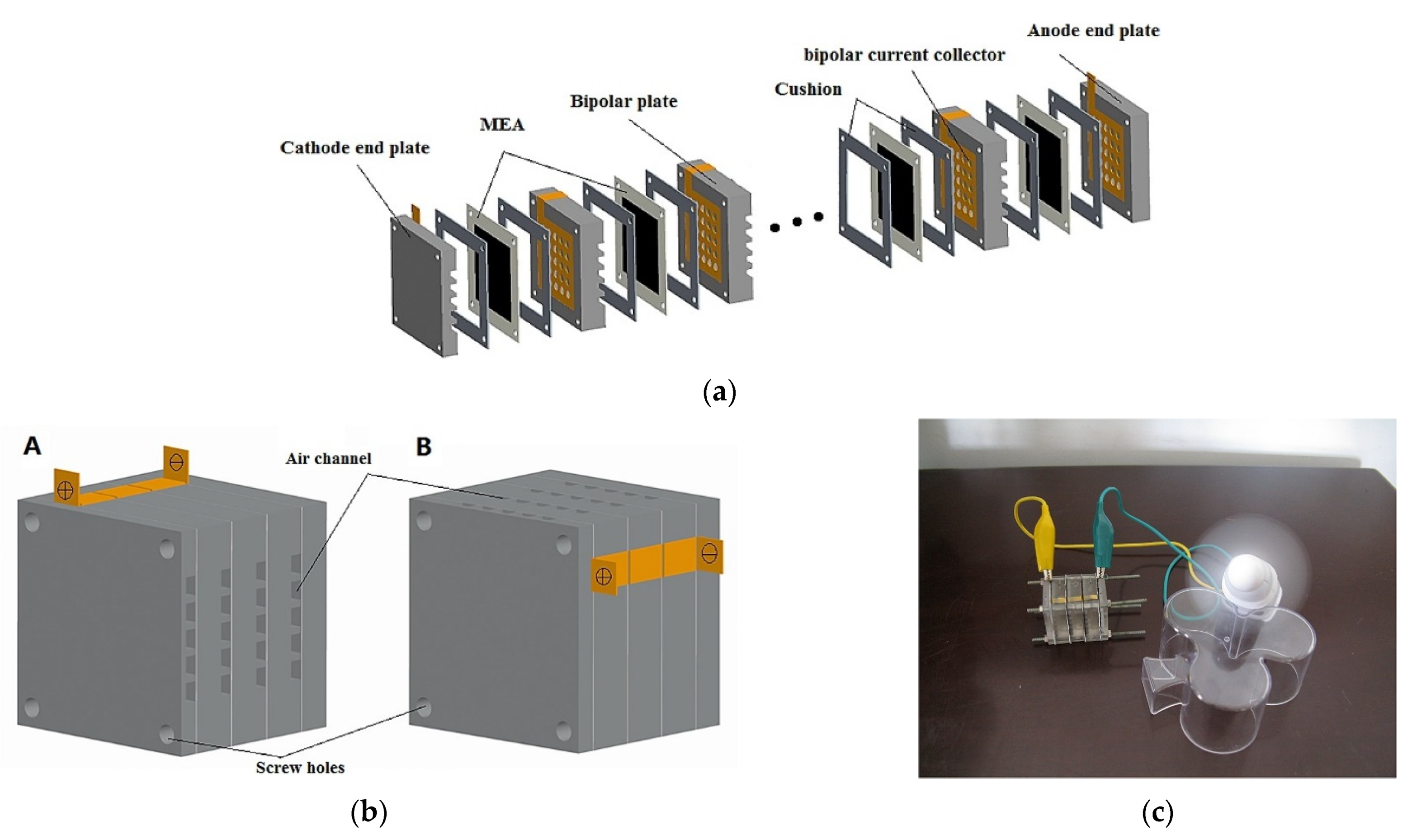
| Stack (2 cells) | 2 | Nafion® 117 | 4 (mg·cm−2) Pt/Ru/Ti | 2 (mg·cm−2) Pt/C, CP (w/MPL) | RT (n.d.) | 1000 | 2.5 | [145] |
| Stack (6 cells) | 2 | Nafion® 117 | 4 (mg·cm−2) Pt/Ru/Ti | 2 (mg·cm−2) Pt/C, CP (w/MPL) | RT (n.d.) | 2900 | 1.7 | [145] |
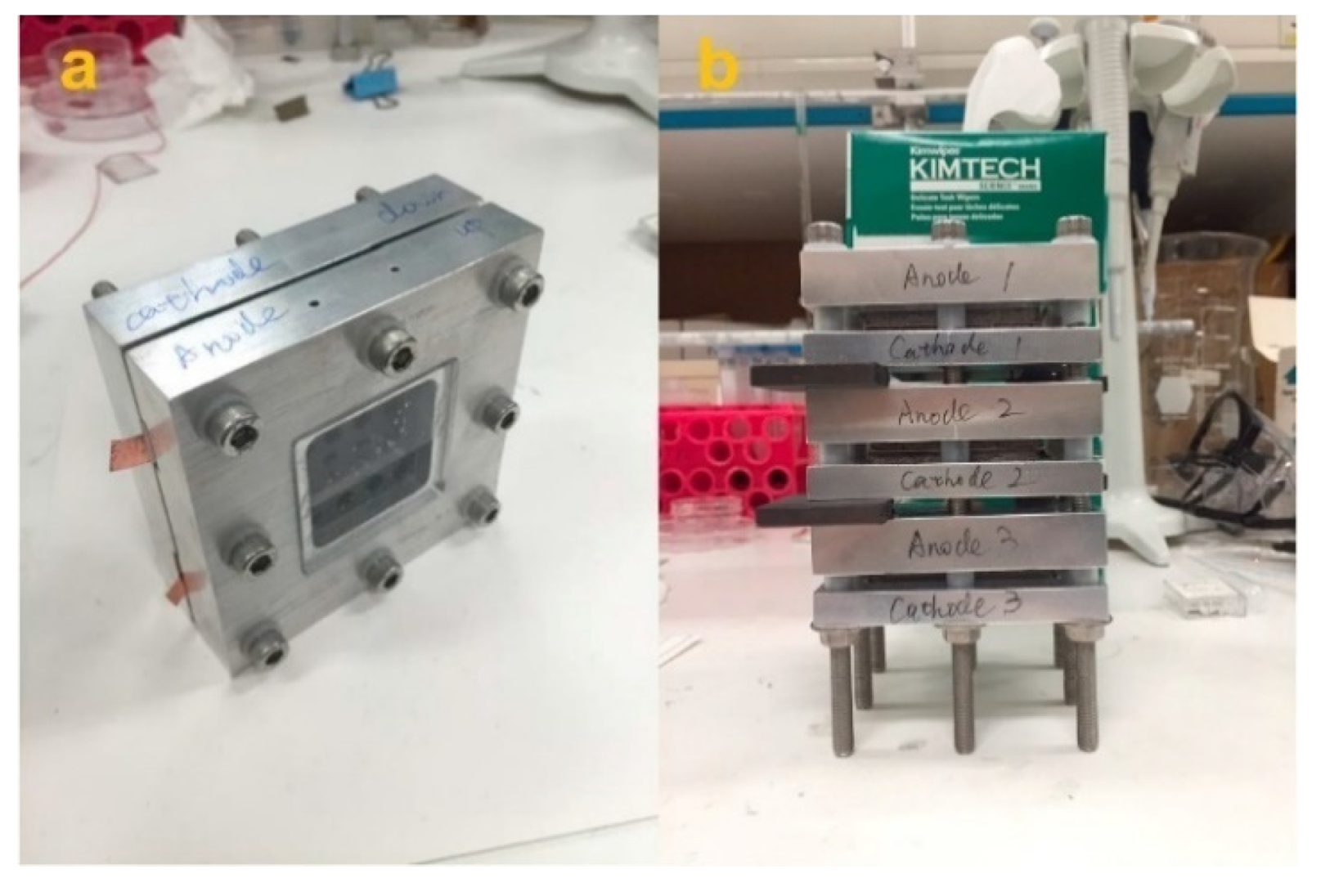
| Stack (4 cells) BP | 3 | PEM (n.d.) | 4 (mg·cm−2) (n.d.), CP | 2 (mg·cm−2) (n.d.), CP | 20 °C | 1260 | 18.7 | [147] |
| Stack (3 cells) MPC16 | 6 | Nafion® 117 | 1.0 (mg·cm−2) Pt/Ru/C, CP | 1.0 (mg·cm−2) Pt/C, CP | 80 °C | 1340 | 25.24 | [148] |
| Single-MPC16 | 6 | Nafion® 117 | 1.0 (mg·cm−2) Pt/Ru/C, CP | 1.0 (mg·cm−2) Pt/C, CP | 85 °C | 452 | 7.91 | [148] |
| Single-MPC9 | 4 | Nafion® 117 | 1.0 (mg·cm−2) Pt/Ru/C, CP | 1.0 (mg·cm−2) Pt/C, CP | 85 °C | 480 | 5.17 | [148] |
3. Other Alcohols and Alternative Oxidants
3.1. Ethanol
3.2. Other Alcohols
3.3. Alternative Oxidants
| Type | Fuel/Oxidant | Membrane | Anode | Cathode | Operating T | OCV (mV) | Max. P (mW·cm−2) | Refs. |
|---|---|---|---|---|---|---|---|---|
| Single | Ethanol 4 M/air | Nafion® 115 | 4 (mg·cm−2) PtRu/C, CC (w/MPL) | 2.0 (mg·cm−2) Pt/C, CC (w/MPL) | 60 °C | ~480 * | 1.124 | [24] |
| Single | Ethanol 2 M and KOH 2 M/air | A201 Tokuyama | 1.3 (mg·cm−2) Pd/C, CP | 2 (mg·cm−2) FeCo/NC, CP | RT (n.d.) | 860 | 28 | [65] |
| Single | Methanol 10% and KOH 2 M/air | A201 Tokuyama | n.d. (mg·cm−2) FeCo@Fe@Pd/CNT-OH, NiF | n.d. (mg·cm−2) FeCo/C, CC | 16 °C | 763 | 21.63 | [155] |
| Single | Methanol 10% and KOH 2 M/air | A201 Tokuyama | n.d. (mg·cm−2) Pd/CNT-OH, NiF | n.d. (mg·cm−2) FeCo/C, CC | 16 °C | 716 | 7.69 | [155] |
| Single | Ethanol 10% and KOH 2 M/air | A201 Tokuyama | n.d. (mg·cm−2) FeCo@Fe@Pd/CNT-OH, NiF | n.d. (mg·cm−2) FeCo/C, CC | 16 °C | 741 | 23.26 | [155] |
| Single | Ethanol 10% and KOH 2 M/air | A201 Tokuyama | n.d. (mg·cm−2) Pd/CNT-OH, NiF | n.d. (mg·cm−2) FeCo/C, CC | 16 °C | 611 | 5.12 | [155] |
| Single | Ethanol 1 M and KOH 1 M/air | A201 Tokuyama | 1.5 (mg·cm−2) Pd/C, NiF | n.d. (mg·cm−2) FeCo/C, CP | 25 °C | 470 | 18 | [160] |
| Single | Ethanol 1 M and KOH 1 M/air | A201 Tokuyama | 1.5 (mg·cm−2) Pd-NiO/C, NiF | n.d. (mg·cm−2) PdC/C, CP | 25 °C | 680 | 26 | [160] |
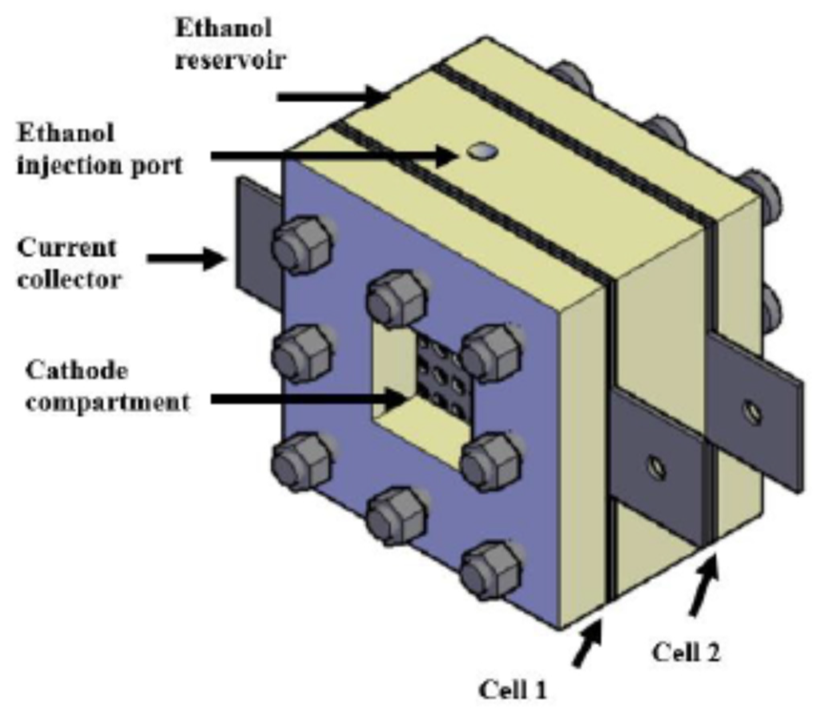
| Stack (2 cells) | Ethanol 2 M/air | Nafion® 115 | 2.0 (mg·cm−2) Pt-Sn/C, CC | 0.5 (mg·cm−2) Pt/C, CC | RT (n.d.) | 1243 | 1.516 | [162] |
| Single | Methanol 4 M and 2-propanol 2 M/air | Nafion® 115 | 4 (mg·cm−2) PtRu/C, CC (w/MPL) | 2 (mg·cm−2) Pt/C, CC (w/MPL) | 25–27 °C | ~510 * | 3.707 | [164] |
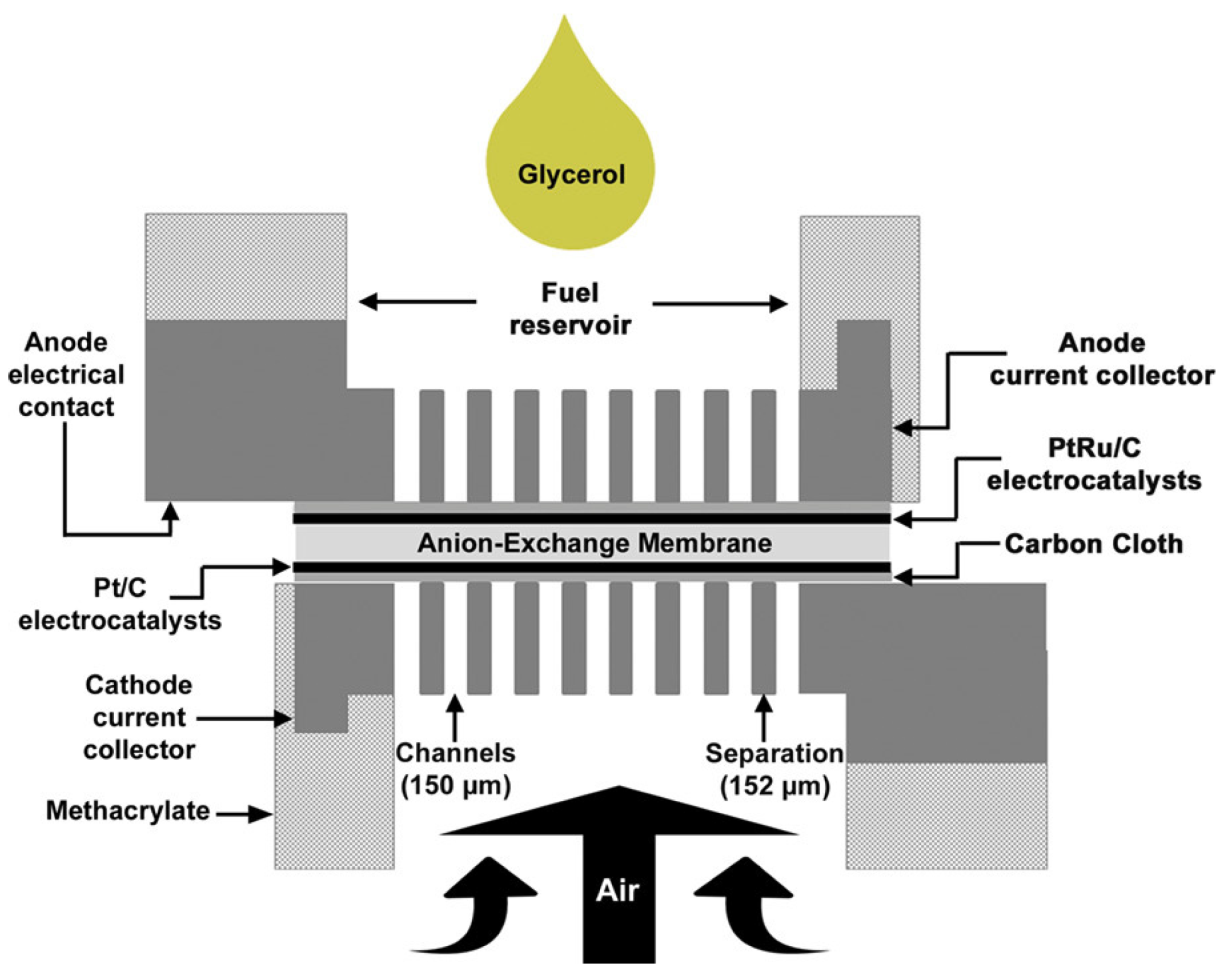
| Single | Glycerol 2 M and NaOH 5 M/air | FAA-3 FumaTech | 1.0 (mg·cm−2) PdAu/VGCNF, CC (w/MPL) | 1.0 (mg·cm−2) Pt/C, CC (w/MPL) | 25 °C | (n.d.) | 3.9 | [168] |
| Single | Glycerol 0.1 M and KOH 0.3 M/air | A201 Tokuyama | 1 (mg·cm−2) PtRu/C, CC | 1 (mg·cm−2) Pt/C, CC | RT (n.d.) | ~600 | 1.008 | [169] |
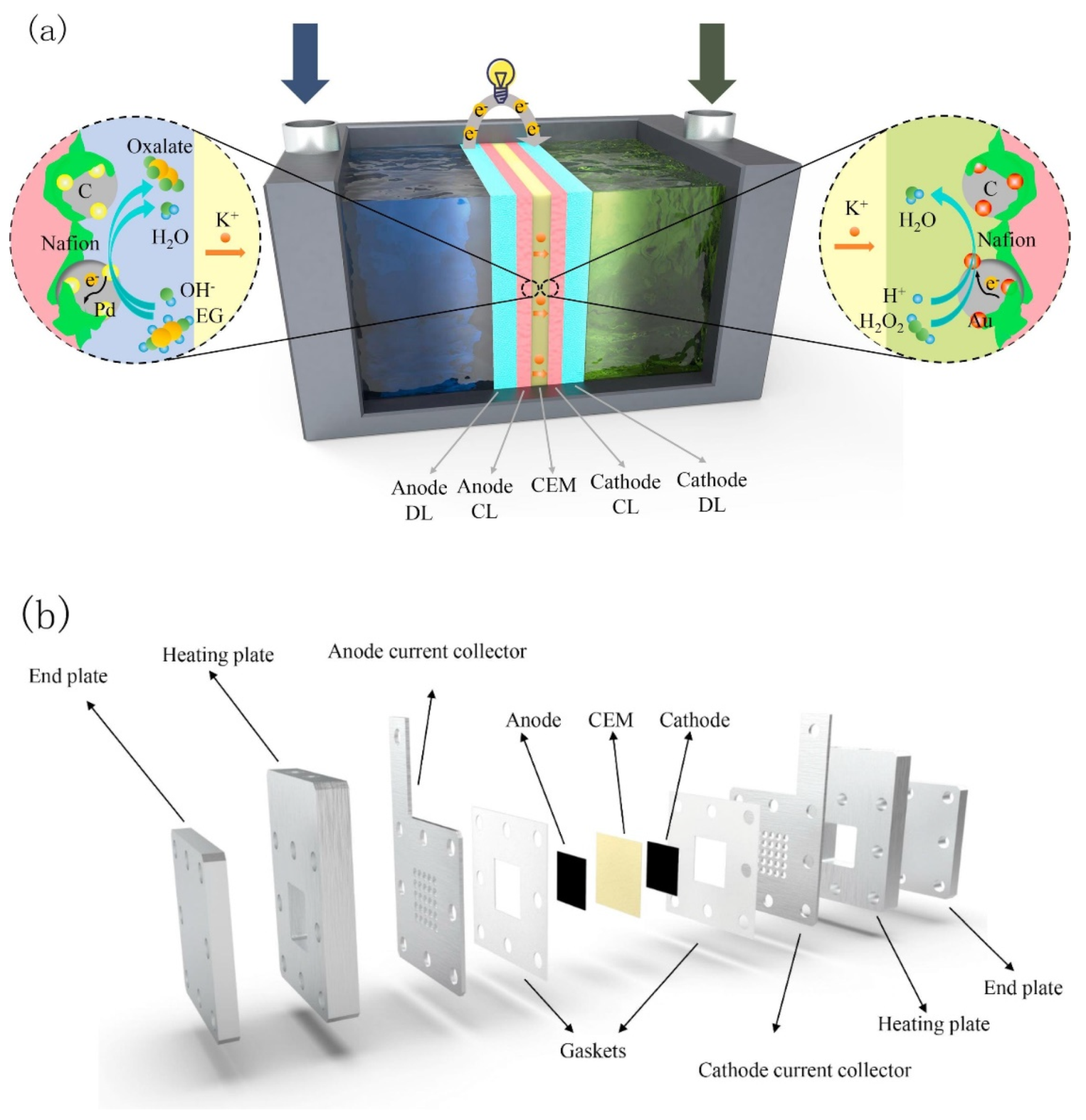
| Single | EG 5 M and KOH 9 M/H2O2 4 M and H2SO4 1 M | Nafion® 211 | 1.0 (mg·cm−2) Pd/C, CC | 2.66 (mg·cm−2) Au/C, CC | 60 °C | 1580 | 65.8 | [172] |
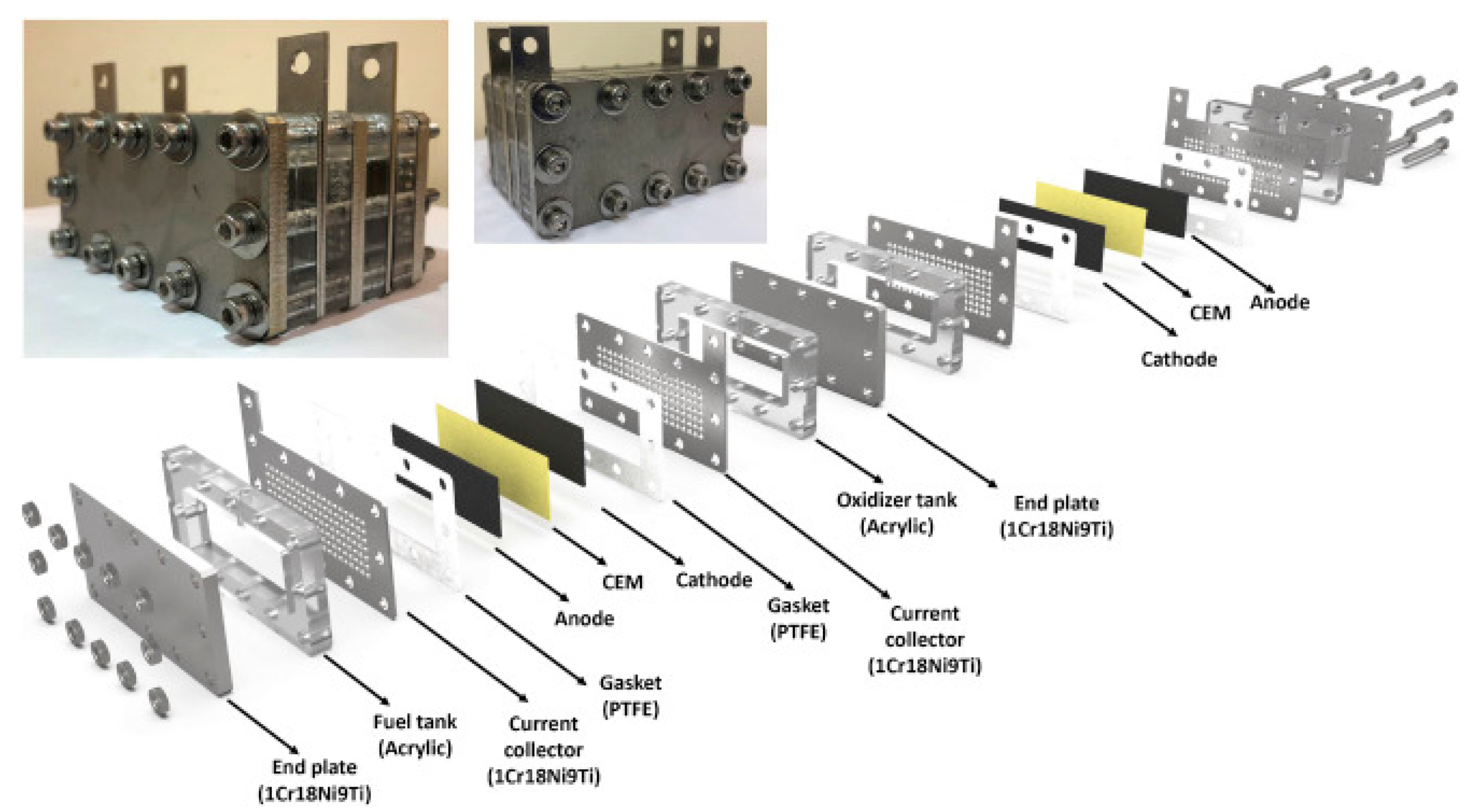
| Stack (2 cells) | EG 5 M and KOH 9 M/H2O2 4 M and H2SO4 1 M | Nafion® 211 | 1.0 (mg·cm−2) Pd/C, CC | 2.75 (mg·cm−2) Au/C, CC | RT (n.d.) | 3000 | 24.5 | [174] |
| Single | Methanol 6 M/H2O2 30% and H2SO4 2 M | Nafion® 115 | 3 (mg·cm−2) PtRu, CC | 6.7 (mg·cm−2) PB/rGO, CC | 85 °C | 600 | 20.5 | [177] |
| Single | EG 1 M and NaOH 4 M/H2O2 5 M and HCl 1.5 M | Nafion® 117 | (n.d.) (mg·cm−2) AuCeO2/C | (n.d.) (mg·cm−2) Pt | 60 °C | ~800 * | 17.30 | [176] |
| Single | Glycerol 1 M and NaOH 4 M/H2O2 5 M and HCl 1.5 M | Nafion® 117 | (n.d.) (mg·cm−2) AuCeO2/C | (n.d.) (mg·cm−2) Pt | 60 °C | ~800 * | 22.96 | [176] |
| Catalyst | DAFC Type | Faradaic Efficiency (%) |
|---|---|---|
| FeCo@Fe@Pd/CNT-OH | AEM-PS-DMFC | 40.48 |
| Pd/CNT-OH | AEM-PS-DMFC | 6.92 |
| FeCo@Fe@Pd/CNT-OH | AEM-PS-DEFC | 86.75 |
| Pd/CNT-OH | AEM-PS-DEFC | 15.65 |
4. Concluding Remarks
Author Contributions
Funding
Conflicts of Interest
Abbreviations
| 3D GF | Three-dimensional graphene frameworks |
| 3DG | Three-dimensional graphene |
| AA | Alkaline–acid |
| ABS | Acrylonitrile butadiene styrene |
| ACL | Anode catalyst layer |
| ACR | Alcohol concentration ratio |
| ADL | Anode diffusion layer |
| AEMs | Anion-exchange membranes |
| AOR | Alcohol oxidation reaction |
| BPs | Bipolar plates |
| CB | Carbon black |
| CC | Carbon cloth |
| CCL | Cathode catalyst layer |
| CCs | Current collectors |
| CDL | Cathode diffusion layer |
| CFSF | Copper fiber sintered felt |
| CGCOB | Crude glycerol from cooking oil biodiesel |
| CGSOB | Crude glycerol from sunflower oil biodiesel |
| CH | Circular-hole array |
| CL | Catalyst layer |
| CNCs | Carbon nanocages |
| CNF | Carbon nanofiber |
| CNT-OH | Carboxylated multiwalled carbon nanotubes |
| CNTs | Carbon nanotubes |
| CNWs | Carbon nanofiber webs |
| CP | Carbon paper |
| CP | Circle pattern |
| CQDs | Carbon quantum dots |
| DAFCs | Direct alcohol fuel cells |
| DEFCs | Direct ethanol fuel cells |
| DEGHPFC | Direct ethylene glycol–hydrogen peroxide fuel cell |
| DFT | Density functional theory |
| DGHPFC | Direct glycerol–hydrogen peroxide fuel cell |
| DMFCs | Direct methanol fuel cells |
| DMHPFC | Direct methanol–hydrogen peroxide fuel cell |
| EEC | Equivalent electric circuit |
| EG | Ethylene glycol |
| EIS | Electrochemical impedance spectroscopy |
| EOR | Ethanol oxidation reaction |
| EtOH | Ethanol |
| G | Glycerol |
| GDL | Gas diffusion layer |
| GO | Graphene oxide |
| GOR | Glycerol oxidation reaction |
| GQDs | Graphene quantum dots |
| HLS | Hill-like structure |
| HPG | High-purity glycerol |
| HPOR | Hydrogen peroxide reduction reaction |
| HPRR | Hydrogen peroxide reduction reaction |
| HSP | Horizontal stripe pattern |
| KP | Karrapo |
| LE | Liquid electrolyte |
| MCDM | Multicriteria decision making |
| MEA | Membrane electrode assembly |
| MEMS | Microelectromechanical systems |
| MeOH | Methanol |
| MOC | Methanol crossover |
| MPC | Magnesia phosphate cement |
| MPL | Microporous layer |
| NiF | Nickel foam |
| NPs | Nanoparticles |
| NRGO | Nitrogen-doped reduced graphene oxide |
| OCV | Open-circuit voltage |
| ORR | Oxygen reduction reaction |
| PAN | Polyacrylonitrile |
| PB | Prussian Blue |
| PC | Polycarbonate |
| PCB | Printed circuit board |
| PD | Power density |
| PEG | Poly(ethylene glycol) |
| PEM | Polymer electrolyte membrane or proton exchange membrane |
| PEMFCs | Polymer electrolyte membrane fuel cells |
| PF | Parallel fence |
| PFr | Pore-former |
| PGM | Platinum group metal |
| PMG | Precious metal group |
| PMMA | Polymethylmethacrylate |
| PS-DAFCs | Passive small direct alcohol fuel cells |
| PS-DMFCs | Passive small direct methanol fuel cells |
| PSO | Particle swarm optimization |
| Pt | Platinum |
| PTFE | Polytetrafluoroethylene |
| rGO | reduced GO |
| RSM | Response surface methodology |
| RT | Room temperature |
| SAP | Super absorbent polymer |
| SCS | Silicone heating sheet |
| SDSS | Sodium dihexyl sulfosuccinate |
| SEM | Scanning electron microscopy |
| SPDG | Saponification process-derived glycerol |
| SS | Stainless steel |
| SSFF | Stainless-steel fiber felt |
| THS | Through-hole silicon |
| UAVs | Unmanned aerial vehicles |
| UAVs | Unmanned aerial vehicles |
| VGCNF | Vapor-grown carbon nanofiber |
| VSP | Vertical strip pattern |
| WML | Water management layer |
References
- IEA. World Energy Outlook 2019 Executive Summary, 2019. Available online: https://iea.blob.core.windows.net/assets/1f6bf453-3317-4799-ae7b-9cc6429c81d8/English-WEO-2019-ES.pdf (accessed on 3 January 2022).
- FCH2JU. Hydrogen Roadmap Europe: A sustainable pathway for the European Energy Transition, 978-92-9246-332-8, 2019. Available online: https://www.fch.europa.eu/sites/default/files/Hydrogen%20Roadmap%20Europe_Report.pdf (accessed on 12 January 2022).
- Krishan, O.; Suhag, S. An updated review of energy storage systems: Classification and applications in distributed generation power systems incorporating renewable energy resources. Int. J. Energy Res. 2019, 43, 6171–6210. [Google Scholar] [CrossRef]
- Staffell, I.; Scamman, D.; Velazquez Abad, A.; Balcombe, P.; Dodds, P.E.; Ekins, P.; Shah, N.; Ward, K.R. The role of hydrogen and fuel cells in the global energy system. Energy Environ. Sci. 2019, 12, 463–491. [Google Scholar] [CrossRef] [Green Version]
- Sazali, N.; Wan Salleh, W.N.; Jamaludin, A.S.; Mhd Razali, M.N. New Perspectives on Fuel Cell Technology: A Brief Review. Membranes 2020, 10, 99. [Google Scholar] [CrossRef] [PubMed]
- Goor, M.; Menkin, S.; Peled, E. High power direct methanol fuel cell for mobility and portable applications. Int. J. Hydrog. Energy 2019, 44, 3138–3143. [Google Scholar] [CrossRef]
- Mohammed, H.; Al-Othman, A.; Nancarrow, P.; Tawalbeh, M.; Assad, M.E.H. Direct hydrocarbon fuel cells: A promising technology for improving energy efficiency. Energy 2019, 172, 207–219. [Google Scholar] [CrossRef]
- Bollella, P.; Lee, I.; Blaauw, D.; Katz, E. A Microelectronic Sensor Device Powered by a Small Implantable Biofuel Cell. ChemPhysChem 2020, 21, 120–128. [Google Scholar] [CrossRef] [Green Version]
- Xiao, X.; Xia, H.-Q.; Wu, R.; Bai, L.; Yan, L.; Magner, E.; Cosnier, S.; Lojou, E.; Zhu, Z.; Liu, A. Tackling the Challenges of Enzymatic (Bio)Fuel. Cells. Chem. Rev. 2019, 119, 9509–9558. [Google Scholar] [CrossRef]
- Sá, M.; Brandão, L. Non-enzymatic direct glucose fuel cells (DGFC): A novel principle towards autonomous electrochemical biosensors. Int. J. Hydrogen Energy 2019, 45, 29749–29762. [Google Scholar] [CrossRef]
- Xu, Q.; Zhang, F.; Xu, L.; Leung, P.; Yang, C.; Li, H. The applications and prospect of fuel cells in medical field: A review. Renew. Sustain. Energy Rev. 2017, 67, 574–580. [Google Scholar] [CrossRef]
- Da Silva, L.M.; Cesar, R.; Moreira, C.M.; Santos, J.H.; De Souza, L.G.; Pires, B.M.; Vicentini, R.; Nunes, W.; Zanin, H. Reviewing the fundamentals of supercapacitors and the difficulties involving the analysis of the electrochemical findings obtained for porous electrode materials. Energy Storage Mater. 2019, 27, 555–590. [Google Scholar] [CrossRef]
- Shaari, N.; Kamarudin, S.K.; Bahru, R.; Osman, S.H.; Md Ishak, N.A.I. Progress and challenges: Review for direct liquid fuel cell. Int. J. Energy Res. 2021, 45, 6644–6688. [Google Scholar] [CrossRef]
- Sharaf, O.Z.; Orhan, M.F. An overview of fuel cell technology: Fundamentals and applications. Renew. Sustain. Energy Rev. 2014, 32, 810–853. [Google Scholar] [CrossRef]
- Alias, M.; Kamarudin, S.; Zainoodin, A.; Masdar, M. Active direct methanol fuel cell: An overview. Int. J. Hydrogen Energy 2020, 45, 19620–19641. [Google Scholar] [CrossRef]
- Pinto, A.M.F.R.; Oliveira, V.B.; Falcão, D.S. Direct Alcohol Fuel Cells for Portable Applications Fundamentals, Engineering and Advances; Elsevier Science: Amsterdam, The Netherlands, 2018. [Google Scholar]
- Falcão, D.; Silva, R.; Rangel, C.; Pinto, A. Performance of an Active Micro Direct Methanol Fuel Cell Using Reduced Catalyst Loading MEAs. Energies 2017, 10, 1683. [Google Scholar] [CrossRef] [Green Version]
- Fadzillah, D.; Kamarudin, S.; Zainoodin, M.; Masdar, M. Critical challenges in the system development of direct alcohol fuel cells as portable power supplies: An overview. Int. J. Hydrogen Energy 2019, 44, 3031–3054. [Google Scholar] [CrossRef]
- Xia, Z.; Zhang, X.; Sun, H.; Wang, S.; Sun, G. Recent advances in multi-scale design and construction of materials for direct methanol fuel cells. Nano Energy 2019, 65, 104048. [Google Scholar] [CrossRef]
- Ong, B.; Kamarudin, S.; Basri, S. Direct liquid fuel cells: A review. Int. J. Hydrogen Energy 2017, 42, 10142–10157. [Google Scholar] [CrossRef]
- Yahya, N.; Kamarudin, S.; Karim, N.; Masdar, M.S.; Loh, K.; Lim, K. Durability and performance of direct glycerol fuel cell with palladium-aurum/vapor grown carbon nanofiber support. Energy Convers. Manag. 2019, 188, 120–130. [Google Scholar] [CrossRef]
- Azam, A.M.I.N.; Lee, S.H.; Masdar, M.S.; Zainoodin, A.M.; Kamarudin, S.K. Parametric study on direct ethanol fuel cell (DEFC) performance and fuel crossover. Int. J. Hydrogen Energy 2019, 44, 8566–8574. [Google Scholar] [CrossRef]
- Yong, Y.; Azam, A.; Masdar, M.; Zainoodin, A.; Kamarudin, S. Anode structure with double-catalyst layers for improving the direct ethanol fuel cell performance. Int. J. Hydrogen Energy 2019, 45, 22302–22314. [Google Scholar] [CrossRef]
- Shrivastava, N.K.; Chadge, R.B.; Ahire, P.; Giri, J.P. Experimental investigation of a passive direct ethanol fuel cell. Ionics 2019, 25, 719–726. [Google Scholar] [CrossRef]
- Oliveira, V.; Pereira, J.; Pinto, A. Modeling of passive direct ethanol fuel cells. Energy 2017, 133, 652–665. [Google Scholar] [CrossRef]
- An, L.; Zhao, T.; Li, Y. Carbon-neutral sustainable energy technology: Direct ethanol fuel cells. Renew. Sustain. Energy Rev. 2015, 50, 1462–1468. [Google Scholar] [CrossRef]
- Kamarudin, M.Z.F.; Kamarudin, S.K.; Masdar, M.S.; Daud, W.R.W. Review: Direct ethanol fuel cells. Int. J. Hydrog. Energy 2013, 38, 9438–9453. [Google Scholar] [CrossRef]
- de Sá, M.; Pinto, A.; Oliveira, V. Passive direct methanol fuel cells as a sustainable alternative to batteries in hearing aid devices–An overview. Int. J. Hydrogen Energy 2022, 47, 16552–16567. [Google Scholar] [CrossRef]
- Carneiro, L.P.; Ferreira, N.S.; Tavares, A.P.; Pinto, A.M.; Mendes, A.; Sales, M.G.F. A passive direct methanol fuel cell as transducer of an electrochemical sensor, applied to the detection of carcinoembryonic antigen. Biosens. Bioelectron. 2020, 175, 112877. [Google Scholar] [CrossRef] [PubMed]
- Larminie, J.; Dicks, A. Fuel Cell Systems Explained, 2nd ed.; John Wiley & Sons Ltd.: England, UK, 2003. [Google Scholar]
- Zhao, T. Micro Fuel Cells—Principles and Applications; Elsevier Inc.: San Diego, CA, USA, 2009. [Google Scholar]
- Kjeang, E.; Djilali, N.; Sinton, D. Chapter 3—Advances in Microfluidic Fuel Cells. In Micro Fuel Cells, Principles and Applications; Academic Press: Cambridge, MA, USA, 2009; pp. 99–139. [Google Scholar]
- Falcão, D.; Oliveira, V.; Rangel, C.; Pinto, A. Review on micro-direct methanol fuel cells. Renew. Sustain. Energy Rev. 2014, 34, 58–70. [Google Scholar] [CrossRef] [Green Version]
- Agnolucci, P. Economics and market prospects of portable fuel cells. Int. J. Hydrogen Energy 2007, 32, 4319–4328. [Google Scholar] [CrossRef]
- Siwal, S.; Thakur, S.; Zhang, Q.; Thakur, V. Electrocatalysts for electrooxidation of direct alcohol fuel cell: Chemistry and applications. Mater. Today Chem. 2019, 14, 100182. [Google Scholar] [CrossRef]
- Zheng, Y.; Wan, X.; Cheng, X.; Cheng, K.; Dai, Z.; Liu, Z. Advanced Catalytic Materials for Ethanol Oxidation in Direct Ethanol Fuel Cells. Catalysts 2020, 10, 166. [Google Scholar] [CrossRef] [Green Version]
- Mansor, M.; Timmiati, S.N.; Lim, K.L.; Wong, W.Y.; Kamarudin, S.K.; Kamarudin, N.H.N. Recent progress of anode catalysts and their support materials for methanol electrooxidation reaction. Int. J. Hydrogen Energy 2019, 44, 14744–14769. [Google Scholar] [CrossRef]
- Tong, Y.; Yan, X.; Liang, J.; Dou, S.X. Metal-Based Electrocatalysts for Methanol Electro-Oxidation: Progress, Opportunities, and Challenges. Small 2019, 17, e1904126. [Google Scholar] [CrossRef] [PubMed]
- Zhao, X.; Liu, Q.; Li, Q.; Chen, L.; Mao, L.; Wang, H.; Chen, S. Two-dimensional electrocatalysts for alcohol oxidation: A critical review. Chem. Eng. J. 2020, 400, 125744. [Google Scholar] [CrossRef]
- Wu, F.; Zhang, L.; Lai, J.; Luque, R.; Niu, W.; Xu, G. Modulating the oxophilic properties of inorganic nanomaterials for electrocatalysis of small carbonaceous molecules. Nano Today 2019, 29, 100802. [Google Scholar] [CrossRef]
- Zhang, J.; Lu, S.; Xiang, Y.; Jiang, S.P. Intrinsic Effect of Carbon Supports on the Activity and Stability of Precious Metal Based Catalysts for Electrocatalytic Alcohol Oxidation in Fuel Cells: A Review. ChemSusChem 2020, 13, 2484–2502. [Google Scholar] [CrossRef]
- Ren, X.; Lv, Q.; Liu, L.; Liu, B.; Wang, Y.; Liu, A.; Wu, G. Current progress of Pt and Pt-based electrocatalysts used for fuel cells. Sustain. Energy Fuels 2020, 4, 15–30. [Google Scholar] [CrossRef]
- Hu, C.; Zhou, Y.; Xiao, M.; Yu, G. Precise size and dominant-facet control of ultra-small Pt nanoparticles for efficient ethylene glycol, methanol and ethanol oxidation electrocatalysts. Int. J. Hydrogen Energy 2020, 45, 4341–4354. [Google Scholar] [CrossRef]
- Yao, D.; Zhang, W.; Ma, Q.; Xu, Q.; Pasupathi, S.; Su, H. Achieving high Pt utilization and superior performance of high temperature polymer electrolyte membrane fuel cell by employing low-Pt-content catalyst and microporous layer free electrode design. J. Power Sources 2019, 426, 124–133. [Google Scholar] [CrossRef]
- Zhang, L.; Doyle-Davis, K.; Sun, X. Pt-Based electrocatalysts with high atom utilization efficiency: From nanostructures to single atoms. Energy Environ. Sci. 2019, 12, 492–517. [Google Scholar] [CrossRef]
- Singh, K.; Tetteh, E.B.; Lee, H.-Y.; Kang, T.-H.; Yu, J.-S. Tailor-Made Pt Catalysts with Improved Oxygen Reduction Reaction Stability/Durability. ACS Catal. 2019, 9, 8622–8645. [Google Scholar] [CrossRef]
- Ercolano, G.; Cavaliere, S.; Rozière, J.; Jones, D.J. Recent developments in electrocatalyst design thrifting noble metals in fuel cells. Curr. Opin. Electrochem. 2018, 9, 271–277. [Google Scholar] [CrossRef]
- Du, L.; Prabhakaran, V.; Xie, X.; Park, S.; Wang, Y.; Shao, Y. Low-PGM and PGM-Free Catalysts for Proton Exchange Membrane Fuel Cells: Stability Challenges and Material Solutions. Adv. Mater. 2020, 33, 1908232. [Google Scholar] [CrossRef] [PubMed]
- Kosmala, T.; Bibent, N.; Sougrati, M.T.; Dražić, G.; Agnoli, S.; Jaouen, F.; Granozzi, G. Stable, Active, and Methanol-Tolerant PGM-Free Surfaces in an Acidic Medium: Electron Tunneling at Play in Pt/FeNC Hybrid Catalysts for Direct Methanol Fuel Cell Cathodes. ACS Catal. 2020, 10, 7475–7485. [Google Scholar] [CrossRef]
- Shi, Q.; He, Y.; Bai, X.; Wang, M.; Cullen, D.A.; Lucero, M.; Zhao, X.; More, K.L.; Zhou, H.; Feng, Z.; et al. Methanol tolerance of atomically dispersed single metal site catalysts: Mechanistic understanding and high-performance direct methanol fuel cells. Energy Environ. Sci. 2020, 13, 3544–3555. [Google Scholar] [CrossRef]
- Baricci, A.; Bisello, A.; Serov, A.; Odgaard, M.; Atanassov, P.; Casalegno, A. Analysis of the effect of catalyst layer thickness on the performance and durability of platinum group metal-free catalysts for polymer electrolyte membrane fuel cells. Sustain. Energy Fuels 2019, 3, 3375–3386. [Google Scholar] [CrossRef]
- Shao, Y.; Dodelet, J.; Wu, G.; Zelenay, P. PGM-Free Cathode Catalysts for PEM Fuel Cells: A Mini-Review on Stability Challenges. Adv. Mater. 2019, 31, e1807615. [Google Scholar] [CrossRef]
- Xu, X.; Xia, Z.; Zhang, X.; Sun, R.; Sun, X.; Li, H.; Wu, C.; Wang, J.; Wang, S.; Sun, G. Atomically dispersed Fe-N-C derived from dual metal-organic frameworks as efficient oxygen reduction electrocatalysts in direct methanol fuel cells. Appl. Catal. B Environ. 2019, 259, 118042. [Google Scholar] [CrossRef]
- Xia, Z.; Xu, X.; Zhang, X.; Li, H.; Wang, S.; Sun, G. Anodic engineering towards high-performance direct methanol fuel cells with non-precious-metal cathode catalysts. J. Mater. Chem. A 2020, 8, 1113–1119. [Google Scholar] [CrossRef]
- Osmieri, L.; Pezzolato, L.; Specchia, S. Recent trends on the application of PGM-free catalysts at the cathode of anion exchange membrane fuel cells. Curr. Opin. Electrochem. 2018, 9, 240–256. [Google Scholar] [CrossRef]
- Zhang, L.; Wilkinson, D.P.; Liu, Y.; Zhang, J. Progress in nanostructured (Fe or Co)/N/C non-noble metal electrocatalysts for fuel cell oxygen reduction reaction. Electrochim. Acta 2018, 262, 326–336. [Google Scholar] [CrossRef]
- Vecchio, C.L.; Serov, A.; Romero, H.; Lubers, A.; Zulevi, B.; Aricò, A.; Baglio, V. Commercial platinum group metal-free cathodic electrocatalysts for highly performed direct methanol fuel cell applications. J. Power Sources 2019, 437, 226948. [Google Scholar] [CrossRef]
- Abdelkareem, M.A.; Sayed, E.; Mohamed, H.O.; Obaid, M.; Rezk, H.; Chae, K.-J. Nonprecious anodic catalysts for low-molecular-hydrocarbon fuel cells: Theoretical consideration and current progress. Prog. Energy Combust. Sci. 2020, 77, 100805. [Google Scholar] [CrossRef]
- de Sá, M.H.; Moreira, C.S.; Pinto, A.M.F.R.; Oliveira, V.B. Recent advances in nanocatalysts (NCs): Design development challenges for DMFC. J. Energy Chem. 2022; Submitted. [Google Scholar]
- Sebastián, D.; Serov, A.; Matanovic, I.; Artyushkova, K.; Atanassov, P.; Arico’, A.S.; Baglio, V. Insights on the extraordinary tolerance to alcohols of Fe-N-C cathode catalysts in highly performing direct alcohol fuel cells. Nano Energy 2017, 34, 195–204. [Google Scholar] [CrossRef] [Green Version]
- Sebastián, D.; Serov, A.; Artyushkova, K.; Gordon, J.; Atanassov, P.; Aricò, A.S.; Baglio, V. High Performance and Cost-Effective Direct Methanol Fuel Cells: Fe-N-C Methanol-Tolerant Oxygen Reduction Reaction Catalysts. ChemSusChem 2016, 9, 1986–1995. [Google Scholar] [CrossRef]
- Martinez, U.; Babu, S.K.; Holby, E.F.; Chung, H.T.; Yin, X.; Zelenay, P. Progress in the Development of Fe-Based PGM-Free Electrocatalysts for the Oxygen Reduction Reaction. Adv. Mater. 2019, 31, e1806545. [Google Scholar] [CrossRef]
- Ehelebe, K.; Ashraf, T.; Hager, S.; Seeberger, D.; Thiele, S.; Cherevko, S. Fuel cell catalyst layer evaluation using a gas diffusion electrode half-cell: Oxygen reduction reaction on Fe-N-C in alkaline media. Electrochem. Commun. 2020, 116, 106761. [Google Scholar] [CrossRef]
- Osmieri, L.; Escudero-Cid, R.; Armandi, M.; Videla, A.M.; Fierro, J.L.G.; Ocón, P.; Specchia, S. Fe-N/C catalysts for oxygen reduction reaction supported on different carbonaceous materials. Performance in acidic and alkaline direct alcohol fuel cells. Appl. Catal. B Environ. 2017, 205, 637–653. [Google Scholar] [CrossRef]
- Osmieri, L.; Zafferoni, C.; Wang, L.; Videla, A.H.A.M.; Lavacchi, A.; Specchia, S. Polypyrrole-Derived Fe−Co−N−C Catalyst for the Oxygen Reduction Reaction: Performance in Alkaline Hydrogen and Ethanol Fuel Cells. ChemElectroChem 2018, 5, 1954–1965. [Google Scholar] [CrossRef]
- Osmieri, L.; Escudero-Cid, R.; Videla, A.H.M.; Ocón, P.; Specchia, S. Application of a non-noble Fe-N-C catalyst for oxygen reduction reaction in an alkaline direct ethanol fuel cell. Renew. Energy 2018, 115, 226–237. [Google Scholar] [CrossRef] [Green Version]
- Mustain, W.E.; Chatenet, M.; Page, M.; Kim, Y.S. Durability challenges of anion exchange membrane fuel cells. Energy Environ. Sci. 2020, 13, 2805–2838. [Google Scholar] [CrossRef]
- Gottesfeld, S.; Dekel, D.R.; Page, M.; Bae, C.; Yan, Y.; Zelenay, P.; Kim, Y.S. Anion exchange membrane fuel cells: Current status and remaining challenges. J. Power Sources 2018, 375, 170–184. [Google Scholar] [CrossRef]
- Krewer, U.; Weinzierl, C.; Ziv, N.; Dekel, D.R. Impact of carbonation processes in anion exchange membrane fuel cells. Electrochim. Acta 2018, 263, 433–446. [Google Scholar] [CrossRef]
- Ziv, N.; Mustain, W.E.; Dekel, D.R. The Effect of Ambient Carbon Dioxide on Anion-Exchange Membrane Fuel Cells. ChemSusChem 2018, 11, 1136–1150. [Google Scholar] [CrossRef]
- Mustain, W.E. Understanding how high-performance anion exchange membrane fuel cells were achieved: Component, interfacial, and cell-level factors. Curr. Opin. Electrochem. 2018, 12, 233–239. [Google Scholar] [CrossRef]
- Pan, Z.; An, L.; Zhao, T.; Tang, Z. Advances and challenges in alkaline anion exchange membrane fuel cells. Prog. Energy Combust. Sci. 2018, 66, 141–175. [Google Scholar] [CrossRef]
- Sarapuu, A.; Kibena-Põldsepp, E.; Borghei, M.; Tammeveski, K. Electrocatalysis of oxygen reduction on heteroatom-doped nanocarbons and transition metal–nitrogen–carbon catalysts for alkaline membrane fuel cells. J. Mater. Chem. A 2018, 6, 776–804. [Google Scholar] [CrossRef]
- An, L.; Zhao, T. Transport phenomena in alkaline direct ethanol fuel cells for sustainable energy production. J. Power Sources 2017, 341, 199–211. [Google Scholar] [CrossRef]
- Borghei, M.; Laocharoen, N.; Kibena-Põldsepp, E.; Johansson, L.-S.; Campbell, J.; Kauppinen, E.; Tammeveski, K.; Rojas, O.J. Porous N,P-doped carbon from coconut shells with high electrocatalytic activity for oxygen reduction: Alternative to Pt-C for alkaline fuel cells. Appl. Catal. B Environ. 2017, 204, 394–402. [Google Scholar] [CrossRef]
- Kanninen, P.; Borghei, M.; Hakanpää, J.; Kauppinen, E.I.; Ruiz, V.; Kallio, T. Temperature dependent performance and catalyst layer properties of PtRu supported on modified few-walled carbon nanotubes for the alkaline direct ethanol fuel cell. J. Electroanal. Chem. 2017, 793, 48–57. [Google Scholar] [CrossRef] [Green Version]
- Ozoemena, K.I. Nanostructured platinum-free electrocatalysts in alkaline direct alcohol fuel cells: Catalyst design, principles and applications. RSC Adv. 2016, 6, 89523–89550. [Google Scholar] [CrossRef] [Green Version]
- Li, Y.; Zhao, T. A passive anion-exchange membrane direct ethanol fuel cell stack and its applications. Int. J. Hydrogen Energy 2016, 41, 20336–20342. [Google Scholar] [CrossRef]
- Varcoe, J.R.; Atanassov, P.; Dekel, D.R.; Herring, A.M.; Hickner, M.A.; Kohl, P.A.; Kucernak, A.R.; Mustain, W.E.; Nijmeijer, K.; Scott, K.; et al. Anion-exchange membranes in electrochemical energy systems. Energy Environ. Sci. 2014, 7, 3135–3191. [Google Scholar] [CrossRef] [Green Version]
- Ramaswamy, N.; Mukerjee, S. Alkaline Anion-Exchange Membrane Fuel Cells: Challenges in Electrocatalysis and Interfacial Charge Transfer. Chem. Rev. 2019, 119, 11945–11979. [Google Scholar] [CrossRef] [PubMed]
- Zakaria, K.; McKay, M.J.; Thimmappa, R.; Hasan, M.; Mamlouk, M.; Scott, K. Direct Glycerol Fuel Cells: Comparison with Direct Methanol and Ethanol Fuel Cells. ChemElectroChem 2019, 6, 2578–2585. [Google Scholar] [CrossRef]
- Yan, X.; Zhao, T.; An, L.; Zhao, G.; Shi, L. A direct methanol–hydrogen peroxide fuel cell with a Prussian Blue cathode. Int. J. Hydrogen Energy 2016, 41, 5135–5140. [Google Scholar] [CrossRef]
- An, L.; Zhao, T.; Zeng, L.; Yan, X. Performance of an alkaline direct ethanol fuel cell with hydrogen peroxide as oxidant. Int. J. Hydrogen Energy 2014, 39, 2320–2324. [Google Scholar] [CrossRef]
- Pan, Z.; An, L.; Wen, C. Recent advances in fuel cells based propulsion systems for unmanned aerial vehicles. Appl. Energy 2019, 240, 473–485. [Google Scholar] [CrossRef]
- Wang, J.; Wang, H.; Fan, Y. Techno-Economic Challenges of Fuel Cell Commercialization. Engineering 2018, 4, 352–360. [Google Scholar] [CrossRef]
- Wang, J. System integration, durability and reliability of fuel cells: Challenges and solutions. Appl. Energy 2017, 189, 460–479. [Google Scholar] [CrossRef]
- Sgroi, M.F.; Zedde, F.; Barbera, O.; Stassi, A.; Sebastián, D.; Lufrano, F.; Baglio, V.; Aricò, A.S.; Bonde, J.L.; Schuster, M. Cost Analysis of Direct Methanol Fuel Cell Stacks for Mass Production. Energies 2016, 9, 1008. [Google Scholar] [CrossRef]
- Dutta, K. Direct Methanol Fuel Cell Technology, 1st ed.; Elsevier: Amsterdam, The Netherlands, 2020; p. 564. [Google Scholar]
- Yuda, A.; Ashok, A.; Kumar, A. A comprehensive and critical review on recent progress in anode catalyst for methanol oxidation reaction. Catal. Rev. 2020, 64, 126–228. [Google Scholar] [CrossRef]
- Samimi, F.; Rahimpour, M.R. Chapter 14—Direct Methanol Fuel Cell. In Methanol Science and Engineering; Elsevier: Amsterdam, The Netherlands, 2018; pp. 381–397. [Google Scholar] [CrossRef]
- Chen, X.; Li, T.; Shen, J.; Hu, Z. From structures, packaging to application: A system-level review for micro direct methanol fuel cell. Renew. Sustain. Energy Rev. 2017, 80, 669–678. [Google Scholar] [CrossRef]
- Zhu, Y.; Gao, L.; Li, J. A Novel Button-Type Micro Direct Methanol Fuel Cell with Graphene Diffusion Layer. Micromachines 2019, 10, 658. [Google Scholar] [CrossRef] [Green Version]
- Zhu, Y.; Zhang, X.; Li, J.; Qi, G. Three-dimensional graphene as gas diffusion layer for micro direct methanol fuel cell. Int. J. Mod. Phys. B 2018, 32, 1850145. [Google Scholar] [CrossRef]
- Abdullah, F.A.; Kamarudin, S.K.; Zainoodina, A.M.; Masdar, M.S. Parametric Studies of Direct Methanol Fuel Cell under Different Modes of Operation. J. Kejuruter. 2020, 32, 159–164. [Google Scholar] [CrossRef]
- Yuan, W.; Su, X.; Zhuang, Z.; Huang, S.; Wang, A.; Tang, Y. Forced under-rib water removal by using expanded metal mesh as flow fields for air-breathing direct methanol fuel cells. Int. J. Hydrogen Energy 2018, 43, 19711–19720. [Google Scholar] [CrossRef]
- Wang, A.; Yuan, W.; Huang, S.; Tang, Y.; Chen, Y. Structural effects of expanded metal mesh used as a flow field for a passive direct methanol fuel cell. Appl. Energy 2017, 208, 184–194. [Google Scholar] [CrossRef]
- Yuan, W.; Han, F.; Chen, Y.; Chen, W.; Hu, J.; Tang, Y. Enhanced Water Management and Fuel Efficiency of a Fully Passive Direct Methanol Fuel Cell with Super-Hydrophilic/-Hydrophobic Cathode Porous Flow-Field. J. Electrochem. Energy Convers. Storage 2018, 15, 031003. [Google Scholar] [CrossRef]
- Hu, J.; Yuan, W.; Chen, W.; Xu, X.; Tang, Y. Fabrication and characterization of superhydrophobic copper fiber sintered felt with a 3D space network structure and their oil–water separation. Appl. Surf. Sci. 2016, 389, 1192–1201. [Google Scholar] [CrossRef]
- Yuan, W.; Fang, G.; Li, Z.; Chen, Y.; Tang, Y. Using Electrospinning-Based Carbon Nanofiber Webs for Methanol Crossover Control in Passive Direct Methanol Fuel Cells. Materials 2018, 11, 71. [Google Scholar] [CrossRef] [PubMed] [Green Version]
- Li, Y.; Zhang, X.; Yuan, W.; Zhang, Y.; Liu, X. A novel CO2 gas removal design for a micro passive direct methanol fuel cell. Energy 2018, 157, 599–607. [Google Scholar] [CrossRef]
- Wang, Y.; Liu, X.W.; Zhang, H.F.; Zhou, Z.P. Fabrication of self-healing super-hydrophobic surfaces on aluminium alloy substrates. AIP Adv. 2015, 5, 041314. [Google Scholar] [CrossRef] [Green Version]
- Xue, R.; Zhang, Y.; Zhong, S.; Liu, X. A hydrophobic layer-based water feedback structure for passive μ-DMFC. Microelectron. Eng. 2018, 190, 57–62. [Google Scholar] [CrossRef]
- Yuan, W.; Zhang, X.; Hou, C.; Zhang, Y.; Wang, H.; Liu, X. Enhanced water management via the optimization of cathode microporous layer using 3D graphene frameworks for direct methanol fuel cell. J. Power Sources 2020, 451, 227800. [Google Scholar] [CrossRef]
- Deng, H.; Zhou, J.; Zhang, Y. A Trilaminar-Catalytic Layered MEA Structure for a Passive Micro-Direct Methanol Fuel Cell. Micromachines 2021, 12, 381. [Google Scholar] [CrossRef] [PubMed]
- Braz, B.; Oliveira, V.; Pinto, A. Optimization of a passive direct methanol fuel cell with different current collector materials. Energy 2020, 208, 118394. [Google Scholar] [CrossRef]
- Braz, B.; Moreira, C.; Oliveira, V.; Pinto, A. Effect of the current collector design on the performance of a passive direct methanol fuel cell. Electrochim. Acta 2019, 300, 306–315. [Google Scholar] [CrossRef]
- Braz, B.; Oliveira, V.; Pinto, A. Experimental studies of the effect of cathode diffusion layer properties on a passive direct methanol fuel cell power output. Int. J. Hydrogen Energy 2019, 44, 19334–19343. [Google Scholar] [CrossRef]
- Braz, B.A.; Oliveira, V.B.; Pinto, A.M.F.R. Experimental Evaluation of the Effect of the Anode Diffusion Layer Properties on the Performance of a Passive Direct Methanol Fuel Cell. Energies 2020, 13, 5198. [Google Scholar] [CrossRef]
- Munjewar, S.S.; Thombre, S.B. Effect of current collector roughness on performance of passive direct methanol fuel cell. Renew. Energy 2019, 138, 272–283. [Google Scholar] [CrossRef]
- Zuo, K.; Yuan, Z.; Cao, C.; Hao, Y. The mass transport based on convection effects in a passive DMFC under open-circuit conditions. Int. J. Hydrogen Energy 2018, 43, 23463–23474. [Google Scholar] [CrossRef]
- Yuan, Z.; Zhang, M.; Zuo, K.; Ren, Y. The effect of gravity on inner transport and cell performance in passive micro direct methanol fuel cell. Energy 2018, 150, 28–37. [Google Scholar] [CrossRef]
- Yuan, Z.; Zuo, K.; Cao, C.; Chen, S.; Chuai, W.; Guo, Z. The whole process, bubble dynamic analysis in two-phase transport of the passive miniature direct methanol fuel cells. J. Power Sources 2019, 416, 9–20. [Google Scholar] [CrossRef]
- Yuan, Z.; Chuai, W.; Guo, Z.; Tu, Z.; Kong, F. The Self-Adaptive Fuel Supply Mechanism in Micro DMFC Based on the Microvalve. Micromachines 2019, 10, 353. [Google Scholar] [CrossRef] [Green Version]
- Yuan, Z.; Chuai, W.; Guo, Z.; Tu, Z.; Kong, F. Investigation of self-adaptive thermal control design in passive direct methanol fuel cell. Energy Storage 2019, 1, 64. [Google Scholar] [CrossRef] [Green Version]
- Yuan, Z.; Chuai, W.; Guo, Z.; Tu, Z.; Kong, F. Thermal Layout Analysis and Design of Direct Methanol Fuel Cells on PCB Based on Novel Particle Swarm Optimization. Micromachines 2019, 10, 641. [Google Scholar] [CrossRef] [Green Version]
- Wang, L.; Yin, L.; Yang, W.; Cheng, Y.; Wen, F.; Liu, C.; Dong, L.; Wang, M. Evaluation of structural aspects and operation environments on the performance of passive micro direct methanol fuel cell. Int. J. Hydrogen Energy 2021, 46, 2594–2605. [Google Scholar] [CrossRef]
- Wang, L.; Zhang, Y.; An, Z.; Huang, S.; Zhou, Z.; Liu, X. Non-isothermal modeling of a small passive direct methanol fuel cell in vertical operation with anode natural convection effect. Energy 2013, 58, 283–295. [Google Scholar] [CrossRef]
- Rao, A.S.; Rashmi, K.R.; Manjunatha, D.V.; Jayarama, A.; Pinto, R. Enhancement of power output in passive micro-direct methanol fuel cells with optimized methanol concentration and trapezoidal flow channels—IOPscience. J. Micromech. Microeng. 2019, 29, 075006. [Google Scholar] [CrossRef]
- Yang, C.-R.; Lu, C.-W.; Fu, P.-C.; Cheng, C.; Chiou, Y.-C.; Lee, R.-T.; Tseng, S.-F. Performance evaluation of μDMFCs based on porous-silicon electrodes and methanol modification. Energy 2020, 192, 116666. [Google Scholar] [CrossRef]
- Abdelkareem, M.A.; Allagui, A.; Sayed, E.; Assad, M.E.H.; Said, Z.; Elsaid, K. Comparative analysis of liquid versus vapor-feed passive direct methanol fuel cells. Renew. Energy 2018, 131, 563–584. [Google Scholar] [CrossRef]
- Abdelkareem, M.A.; Sayed, E.T.; Nakagawa, N. Significance of diffusion layers on the performance of liquid and vapor feed passive direct methanol fuel cells. Energy 2020, 209, 118492. [Google Scholar] [CrossRef]
- Oliveira, V.; Pereira, J.; Pinto, A. Effect of anode diffusion layer (GDL) on the performance of a passive direct methanol fuel cell (DMFC). Int. J. Hydrogen Energy 2016, 41, 19455–19462. [Google Scholar] [CrossRef]
- Nakajima, A. Design of hydrophobic surfaces for liquid droplet control. NPG Asia Mater. 2011, 3, 49–56. [Google Scholar] [CrossRef] [Green Version]
- Zuo, K.; Yuan, Z. Design and experimental analysis of a dual-cavity high-concentration adaptive passive micro direct methanol fuel cell. Int. J. Energy Res. 2021, 45, 5359–5368. [Google Scholar] [CrossRef]
- Lu, G.; Ning, F.; Wei, J.; Li, Y.; Bai, C.; Shen, Y.; Li, Y.; Zhou, X. All-solid-state passive direct methanol fuel cells with great orientation stability and high energy density based on solid methanol fuels. J. Power Sources 2020, 450, 227669. [Google Scholar] [CrossRef]
- Boni, M.; Surapaneni, S.R.; Golagani, N.S.; Manupati, S.K. Experimental investigations on the effect of current collector open ratio on the performance of a passive direct methanol fuel cell with liquid electrolyte layer. Chem. Pap. 2021, 75, 27–38. [Google Scholar] [CrossRef]
- Boni, M.; Rao, S.S.; Srinivasulu, G.N. Influence of intermediate liquid electrolyte layer on the performance of passive direct methanol fuel cell. Int. J. Green Energy 2019, 16, 1475–1484. [Google Scholar] [CrossRef]
- Ramli, Z.A.C.; Kamarudin, S.K. Platinum-Based Catalysts on Various Carbon Supports and Conducting Polymers for Direct Methanol Fuel Cell Applications: A Review. Nanoscale Res. Lett. 2018, 13, 1–25. [Google Scholar] [CrossRef] [Green Version]
- Ishak, N.; Kamarudin, S.; Timmiati, S.; Karim, N.; Basri, S. Biogenic platinum from agricultural wastes extract for improved methanol oxidation reaction in direct methanol fuel cell. J. Adv. Res. 2020, 28, 63–75. [Google Scholar] [CrossRef] [PubMed]
- Shaari, N.; Kamarudin, S.K. Current status, opportunities, and challenges in fuel cell catalytic application of aerogels. Int. J. Energy Res. 2019, 43, 2447–2467. [Google Scholar] [CrossRef]
- Shaari, N.; Kamarudin, S.K.; Bahru, R. Carbon and graphene quantum dots in fuel cell application: An overview. Int. J. Energy Res. 2021, 45, 1396–1424. [Google Scholar] [CrossRef]
- Jeong, W.; Chang, I.; Ryu, S.; Zheng, C.; Cha, S.W.; Park, T. Cost-effective and durable Ru-sputtered Pt/C-based membrane–electrode assembly for passive direct methanol fuel cells. AIP Adv. 2019, 9, 095016. [Google Scholar] [CrossRef]
- Jeong, W.; Cho, G.Y.; Cha, S.W.; Park, T. Surface Roughening of Electrolyte Membrane for Pt- and Ru-Sputtered Passive Direct Methanol Fuel Cells. Materials 2019, 12, 3969. [Google Scholar] [CrossRef] [Green Version]
- Fard, H.F.; Khodaverdi, M.; Pourfayaz, F.; Ahmadi, M.H. Application of N-doped carbon nanotube-supported Pt-Ru as electrocatalyst layer in passive direct methanol fuel cell. Int. J. Hydrogen Energy 2020, 45, 25307–25316. [Google Scholar] [CrossRef]
- Abdullah, N.; Kamarudin, S.K.; Shyuan, L.K. Novel Anodic Catalyst Support for Direct Methanol Fuel Cell: Characterizations and Single-Cell Performances. Nanoscale Res. Lett. 2018, 13, 1–13. [Google Scholar] [CrossRef] [Green Version]
- Abdullah, N.; Kamarudin, S.; Shyuan, L.; Karim, N. Synthesis and optimization of PtRu/TiO2-CNF anodic catalyst for direct methanol fuel cell. Int. J. Hydrogen Energy 2019, 44, 30543–30552. [Google Scholar] [CrossRef]
- Alias, M.; Kamarudin, S.; Zainoodin, A.; Masdar, M. Structural mechanism investigation on methanol crossover and stability of a passive direct methanol fuel cell performance via modified micro-porous layer. Int. J. Energy Res. 2021, 45, 12928–12943. [Google Scholar] [CrossRef]
- Ramli, Z.A.C.; Kamarudin, S.K.; Basri, S.; Zainoodin, A.M. The potential of novel carbon nanocages as a carbon support for an enhanced methanol electro-oxidation reaction in a direct methanol fuel cell. Int. J. Energy Res. 2020, 44, 10071–10086. [Google Scholar] [CrossRef]
- Golmohammadi, F.; Amiri, M. Fabrication of MEA from Biomass-Based Carbon Nanofibers Composited with Nickel-Cobalt Oxides as a New Electrocatalyst for Oxygen Reduction Reaction in Passive Direct Methanol Fuel Cells. Electrocatalysis 2020, 11, 485–496. [Google Scholar] [CrossRef]
- Amiri, M.; Golmohammadi, F. Biomass derived hierarchical 3D graphene framework for high performance energy storage devices. J. Electroanal. Chem. 2019, 849, 113388. [Google Scholar] [CrossRef]
- Farzaneh, A.; Goharshadi, E.K.; Gharibi, H.; Saghatoleslami, N.; Ahmadzadeh, H. Insights on the superior performance of nanostructured nitrogen-doped reduced graphene oxide in comparison with commercial Pt/C as cathode electrocatalyst layer of passive direct methanol fuel cell. Electrochim. Acta 2019, 306, 220–228. [Google Scholar] [CrossRef]
- Farzaneh, A.; Saghatoleslami, N.; Goharshadi, E.K.; Gharibi, H.; Ahmadzadeh, H. 3-D mesoporous nitrogen-doped reduced graphene oxide as an efficient metal-free electrocatalyst for oxygen reduction reaction in alkaline fuel cells: Role of π and lone pair electrons. Electrochim. Acta 2016, 222, 608–618. [Google Scholar] [CrossRef]
- Ismail, A.; Kamarudin, S.K.; Daud, W.R.W.; Masdar, S.; Hasran, U.A. Development of optimisation model for direct methanol fuel cells via cell integrated network. Int. J. Hydrog. Energy 2019, 44, 30606–30617. [Google Scholar] [CrossRef]
- Fang, S.; Liu, Y.; Zhao, C.; Huang, L.; Zhong, Z.; Wang, Y. Polarization analysis of a micro direct methanol fuel cell stack based on Debye-Hückel ionic atmosphere theory. Energy 2021, 222, 119907. [Google Scholar] [CrossRef]
- Abraham, B.G.; Chetty, R. Design and fabrication of a quick-fit architecture air breathing direct methanol fuel cell. Int. J. Hydrogen Energy 2021, 46, 6845–6856. [Google Scholar] [CrossRef]
- Abraham, B.G.; Bhaskaran, R.; Chetty, R. Electrodeposited Bimetallic (PtPd, PtRu, PtSn) Catalysts on Titanium Support for Methanol Oxidation in Direct Methanol Fuel Cells. J. Electrochem. Soc. 2020, 167, 024512. [Google Scholar] [CrossRef]
- Wang, L.; Yuan, Z.; Wen, F.; Cheng, Y.; Zhang, Y.; Wang, G. A bipolar passive DMFC stack for portable applications. Energy 2017, 144, 587–593. [Google Scholar] [CrossRef]
- Hao, W.; Ma, H.; Sun, G.; Li, Z. Magnesia phosphate cement composite bipolar plates for passive type direct methanol fuel cells. Energy 2019, 168, 80–87. [Google Scholar] [CrossRef]
- Hao, W.; Ma, H.; Lu, Z.; Sun, G.; Li, Z. Design of magnesium phosphate cement based composite for high performance bipolar plate of fuel cells. RSC Adv. 2016, 6, 56711–56720. [Google Scholar] [CrossRef]
- Ma, H.; Xu, B. Potential to design magnesium potassium phosphate cement paste based on an optimal magnesia-to-phosphate ratio. Mater. Des. 2017, 118, 81–88. [Google Scholar] [CrossRef]
- Raso, O.S.M.A.; Navarro, E.; Leo, T.J. Selection of thermoplastic polymers for use as bipolar plates in direct methanol fuel cell applications. Mater. Des. 2019, 183, 108148. [Google Scholar] [CrossRef]
- Abdelkareem, M.A.; Elsaid, K.; Wilberforce, T.; Kamil, M.; Sayed, E.T.; Olabi, A. Environmental aspects of fuel cells: A review. Sci. Total Environ. 2021, 752, 141803. [Google Scholar] [CrossRef]
- Elsaid, K.; Abdelfatah, S.; Elabsir, A.M.A.; Hassiba, R.J.; Ghouri, Z.K.; Vechot, L. Direct alcohol fuel cells: Assessment of the fuel’s safety and health aspects. Int. J. Hydrogen Energy 2021, 46, 30658–30668. [Google Scholar] [CrossRef]
- Pereira, J.; Falcão, D.; Oliveira, V.; Pinto, A. Performance of a passive direct ethanol fuel cell. J. Power Sources 2014, 256, 14–19. [Google Scholar] [CrossRef]
- Fashedemi, O.O.; Mwonga, P.V.; Miller, H.A.; Maphanga, R.R.; Vizza, F.; Ozoemena, K.I. Performance of Pd@FeCo Catalyst in Anion Exchange Membrane Alcohol Fuel Cells. Electrocatalysis 2021, 12, 295–309. [Google Scholar] [CrossRef]
- Fashedemi, O.O.; Julies, B.; Ozoemena, K.I. Synthesis of Pd-coated FeCo@Fe/C core–shell nanoparticles: Microwave-induced ‘top-down’ nanostructuring and decoration. Chem. Commun. 2013, 49, 2034–2036. [Google Scholar] [CrossRef]
- Fashedemi, O.O.; Ozoemena, K.I. Enhanced methanol oxidation and oxygen reduction reactions on palladium-decorated FeCo@Fe/C core–shell nanocatalysts in alkaline medium. Phys. Chem. Chem. Phys. 2013, 15, 20982–20991. [Google Scholar] [CrossRef]
- Fashedemi, O.O.; Ozoemena, K.I. Comparative electrocatalytic oxidation of ethanol, ethylene glycol and glycerol in alkaline medium at Pd-decorated FeCo@Fe/C core-shell nanocatalysts. Electrochim. Acta 2014, 128, 279–286. [Google Scholar] [CrossRef]
- Fashedemi, O.O.; Miller, H.A.; Marchionni, A.; Vizza, F.; Ozoemena, K.I. Electro-oxidation of ethylene glycol and glycerol at palladium-decorated FeCo@Fe core–shell nanocatalysts for alkaline direct alcohol fuel cells: Functionalized MWCNT supports and impact on product selectivity. J. Mater. Chem. A 2015, 3, 7145–7156. [Google Scholar] [CrossRef] [Green Version]
- Fuku, X.; Modibedi, M.; Matinise, N.; Mokoena, P.; Xaba, N.; Mathe, M. Single step synthesis of bio-inspired NiO/C as Pd support catalyst for dual application: Alkaline direct ethanol fuel cell and CO2 electro-reduction. J. Colloid Interface Sci. 2019, 545, 138–152. [Google Scholar] [CrossRef] [PubMed]
- Khalil, M.; Kadja, G.T.; Ilmi, M.M. Advanced nanomaterials for catalysis: Current progress in fine chemical synthesis, hydrocarbon processing, and renewable energy. J. Ind. Eng. Chem. 2020, 93, 78–100. [Google Scholar] [CrossRef]
- Ekdharmasuit, P. Performance and Ethanol Crossover of Passive Direct Ethanol Fuel Cell Stack. E3S Web Conf. 2020, 141, 01008. [Google Scholar] [CrossRef]
- Gojkovic, S.; Tripkovic, A.; Stevanovic, R. Mixtures of methanol and 2-propanol as a potential fuel for direct alcohol fuel cells. J. Serbian Chem. Soc. 2007, 72, 1419–1425. [Google Scholar] [CrossRef]
- Munjewar, S.S.; Thombre, S.B.; Patil, A.P. Passive direct alcohol fuel cell using methanol and 2-propanol mixture as a fuel. Ionics 2019, 25, 2231–2241. [Google Scholar] [CrossRef]
- Coutanceau, C.; Baranton, S.; Kouamé, R.S.B. Selective Electrooxidation of Glycerol into Value-Added Chemicals: A Short Overview. Front. Chem. 2019, 7, 100. [Google Scholar] [CrossRef]
- Antolini, E. Glycerol Electro-Oxidation in Alkaline Media and Alkaline Direct Glycerol Fuel Cells. Catalysts 2019, 9, 980. [Google Scholar] [CrossRef] [Green Version]
- Othman, P.N.A.M.; Karim, N.A.; Kamarudin, S.K. Research and innovation in the electrocatalyst development toward glycerol oxidation reaction. Int. J. Energy Res. 2021, 45, 12693–12727. [Google Scholar] [CrossRef]
- Yahya, N.; Kamarudin, S.K.; Karim, N.A.; Basri, S.; Zanoodin, A.M. Nanostructured Pd-Based Electrocatalyst and Membrane Electrode Assembly Behavior in a Passive Direct Glycerol Fuel Cell. Nanoscale Res. Lett. 2019, 14, 1–17. [Google Scholar] [CrossRef]
- Olivares-Ramírez, J.M.; Dector, A.; Bañuelos-Días, J.A.; Amaya-Cruz, D.M.; Ortiz-Verdín, A.; Jiménez-Sandoval, O.; Sabaté, N.; Esquivel, J.P. Evaluation of a Passive Anion-Exchange Membrane Micro Fuel Cell Using Glycerol from Several Sources. Fuel Cells 2019, 19, 10–18. [Google Scholar] [CrossRef] [Green Version]
- Pan, Z.; Huang, B.; An, L. Performance of a hybrid direct ethylene glycol fuel cell. Int. J. Energy Res. 2019, 43, 2583–2591. [Google Scholar] [CrossRef]
- Pan, Z.; Bi, Y.; An, L. A cost-effective and chemically stable electrode binder for alkaline-acid direct ethylene glycol fuel cells. Appl. Energy 2020, 258, 114060. [Google Scholar] [CrossRef]
- Pan, Z.; Bi, Y.; An, L. Performance characteristics of a passive direct ethylene glycol fuel cell with hydrogen peroxide as oxidant. Appl. Energy 2019, 250, 846–854. [Google Scholar] [CrossRef]
- Pan, Z.; Bi, Y.; An, L. Mathematical modeling of direct ethylene glycol fuel cells incorporating the effect of the competitive adsorption. Appl. Therm. Eng. 2019, 147, 1115–1124. [Google Scholar] [CrossRef]
- Pan, Z.; Zhuang, H.; Bi, Y.; An, L. A direct ethylene glycol fuel cell stack as air-independent power sources for underwater and outer space applications. J. Power Sources 2019, 437, 226944. [Google Scholar] [CrossRef]
- An, L.; Zhao, T.; Chai, Z.; Zeng, L.; Tan, P. Modeling of the mixed potential in hydrogen peroxide-based fuel cells. Int. J. Hydrogen Energy 2014, 39, 7407–7416. [Google Scholar] [CrossRef]
- Kepenienė, V.; Stagniūnaitė, R.; Balčiūnaitė, A.; Tamašauskaitė-Tamašiūnaitė, L.; Norkus, E. Microwave-assisted synthesis of a AuCeO2/C catalyst and its application for the oxidation of alcohols in an alkaline medium. New J. Chem. 2020, 44, 18308–18318. [Google Scholar] [CrossRef]
- Lu, B.; Yuan, W.; Su, X.; Zhuang, Z.; Ke, Y.; Tang, Y. Passive Direct Methanol–Hydrogen Peroxide Fuel Cell with Reduced Graphene Oxide–Supported Prussian Blue as Catalyst. Energy Technol. 2020, 8, 1901360. [Google Scholar] [CrossRef]


| Field | Fuel | Products | Manufacturer | Characteristics |
|---|---|---|---|---|
| Laptop | Methanol | CD-ROM-sized fuel cell pack | Antig Technology | Electric power of 45 W for 8 h of normal laptop use |
| Methanol | A laptop docking station | Samsung | Maximum output of 20 W | |
| Methanol | Battery charger | Panasonic | Provided between 10 W and 20 W of power with 200 mL of methanol | |
| Methanol | Fuel cell notebook PCs | Antig Technology & Toshiba | Produced power of 10 W and voltage of 7.2 V | |
| Military/industrial | Methanol | Off-grid power generators | SFC Energy | Power output of 500 W |
| Methanol | Army field power pack | SFC Energy | Power output of 250 W for the larger unit at 12 or 24 V and 100 W at 28 V for the smaller one | |
| Methanol | Portable generators, chargers, and batteries | SFC Energy | Capacity of 50 W | |
| Medical | Methanol | Hearing aid | Danish Technological Institute (DTI)/WIDEX® | Supply 2.5 mW continuously for 24 h at a voltage above 350 mV with less than 200 μL of methanol |
| Telecommunication | Methanol | Battery charger | Antig Technology | Power output 3 W and voltage of 5.5 V |
| Methanol | Dynario™ (Battery charger) | Toshiba | Power output of 2 W with a single injection of 14 mL of concentrated methanol solution | |
| Methanol | Mobile and remote power source | Neah Power System | Power density level exceeding 80 mW/cm2 | |
| Others | Ethanol | Power pack | NDC Power | Power output of 3–250 W and operational time 3700 h |
| Methanol | Bio-energy discovery kit | Horizon Fuel Cell Technology | Generated power of 10 mW | |
| Methanol | Mobile audio player | Toshiba and Hitachi | Capacity of 100 mW for 35 h player usage with single 3.5 mL or 300 mW for 60 h with single 10 mL of concentrated methanol solution |
Publisher’s Note: MDPI stays neutral with regard to jurisdictional claims in published maps and institutional affiliations. |
© 2022 by the authors. Licensee MDPI, Basel, Switzerland. This article is an open access article distributed under the terms and conditions of the Creative Commons Attribution (CC BY) license (https://creativecommons.org/licenses/by/4.0/).
Share and Cite
de Sá, M.H.; Pinto, A.M.F.R.; Oliveira, V.B. Passive Small Direct Alcohol Fuel Cells for Low-Power Portable Applications: Assessment Based on Innovative Increments since 2018. Energies 2022, 15, 3787. https://0-doi-org.brum.beds.ac.uk/10.3390/en15103787
de Sá MH, Pinto AMFR, Oliveira VB. Passive Small Direct Alcohol Fuel Cells for Low-Power Portable Applications: Assessment Based on Innovative Increments since 2018. Energies. 2022; 15(10):3787. https://0-doi-org.brum.beds.ac.uk/10.3390/en15103787
Chicago/Turabian Stylede Sá, Maria H., Alexandra M. F. R. Pinto, and Vânia B. Oliveira. 2022. "Passive Small Direct Alcohol Fuel Cells for Low-Power Portable Applications: Assessment Based on Innovative Increments since 2018" Energies 15, no. 10: 3787. https://0-doi-org.brum.beds.ac.uk/10.3390/en15103787