
Magnetic Circuit Design and Experiment of Novel Lorentz Magnetic Bearing with Double Air Gap
1
School of Mechanical Engineering, Tiangong University, Tianjin 300387, China
2
Institute of Precision Electromagnetic Equipment and Advanced Measurement Technology, Beijing Institute of Petrochemical Technology, Beijing 102617, China
*
Author to whom correspondence should be addressed.
Energies 2022, 15(13), 4830; https://0-doi-org.brum.beds.ac.uk/10.3390/en15134830
Submission received: 6 March 2022
/
Revised: 27 June 2022
/
Accepted: 28 June 2022
/
Published: 1 July 2022
(This article belongs to the Special Issue Design and Control of Flywheel Energy Storage Systems)
Abstract
:A uniform magnetic density distribution in the air gap is key for the Lorentz magnetic bearing to achieve high precision control and large torque output. To overcome the small magnetic field strength in an explicit magnetic bearing and a high magnetic density fluctuation rate in an implicit Lorentz magnetic bearing, a second air gap design method is proposed based on the maximum magnetic density distribution in the winding area. A novel Lorentz bearing with a double second air gap is designed. The maximum magnetic field strength in the winding area is calculated by the finite element method, and the structure of the double second air gap is designed. To reduce the calculation error of the magnetic field strength, the division of the reluctance by the magnetic induction line is proposed. The reluctance calculation formula is given. Based on Ohm’s law, the calculation of the magnetic field strength is obtained. Finally, a prototype of the novel Lorentz magnetic bearing is made. The magnetic field strength in the winding area and the magnetic density fluctuation rate are measured with a magnetic density measurement instrument. The maximum magnetic flux density in the winding area is 0.631 T, and the magnetic field strength is 0.58%. Less difference is found between the measurement result and the finite element result.
1. Introduction
A spacecraft’s high-precision and high-stability is guaranteed by attitude control, and the attitude control is mainly realized by the reaction propulsion system, the magnetic torque device, the inertial actuator, etc. [1]. The inertial actuators are widely used in long-term spacecraft working as they have the advantages of not consuming working fluids, generating more precise control moments and so on [2]. The inertial actuators rotor has two types of support methods: mechanical bearing support and magnetic bearing support. The output torque accuracy of the rotor of the mechanical bearing support was interfered by the friction torque, mechanical vibration and viscous torque, which restricts the application of the spacecraft attitude control. On the contrary, the output torque accuracy of the rotor of the magnetic bearing support has a high output torque accuracy as on the friction torque, mechanical vibration and viscous torque. The inertial actuators, whose rotors are supported by a magnetic bearing, include a magnetic reaction flywheel [3], a magnetic biased momentum wheel [4], a magnetic levitation control moment gyroscope [5], a magnetic levitation control, a sensitive gyroscope and so on [6]. The magnetic reaction flywheel and the biased momentum wheel are mainly used in small spacecraft attitude stability control as they have a high-precision output control torque by changing their rotor speed. The magnetic levitation control moment gyroscope was used for attitude control of large spacecrafts and attitude maneuver of medium-sized spacecrafts, as a large gyro control moment with a low torque accuracy functions by driving the high-speed rotor precession through the frame motor. The magnetic levitation control and sensitive gyroscope is a novel inertial actuator. By using a magnetic levitation configuration combining spherical magnetic bearings and Lorentzian magnetic bearings, it has the attitude control of a magnetic levitation control moment gyro, the attitude sensitivity of a rotor rate gyro and vibration angular rate detection and suppression. The three-loop fusion attitude control was used to achieve spacecraft attitude with ultra-precision, ultra-stability, ultra-sensitivity and ultra-static attitude control. For all these magnetic inertial actuators, the Lorenz magnetic bearing is the core component to achieve an ultra-precise and ultra-sensitive attitude control for magnetic inertial actuators [7].
Lorentz magnetic bearings are magnetic bearings that use Lorentz force to output force and torque, which were first used in quartz accelerometers to achieve acceleration sensitivity [8]. The magnetic field strength at the air gap is small as only a single-sided magnet was used. It also can’t be used as an actuator. To improve the output force, a single-turn Lorentz magnetic bearing was designed by Bosch Arma [9]. By reducing the width of the winding area, a high-precision sensitivity function was achieved. To enhance the magneto-dynamic potential, a single-sided double-turn Lorentz magnetic bearing based on the single-turn magnet steel Lorentz magnetic was developed by Alcatel [10]. By increasing the number of permanent magnet rings and the magnetisation length, the magnetic bearing has a larger deflection stiffness. Based on the literature [11], a Lorentz magnetic bearing with a double side and a double ring magnet was developed by Beihang. By analyzing the air gap flux of the bearing, the air gap radial flux model was established, and then the control torque could be calculated with the model. In the literature [12], the cylindrical permanent magnets were replaced by the trapezoidal permanent magnets to improve the magnetic induction intensity of the air gap and increase the output control torque of the bearing. As the air gap of Lorentz magnetic bearings in the references [13] is cylindrical, they do not meet the requirements of large-angle control. To improve the deflection angle of the bearing, spherical permanent magnets were used. With a spherical gap, the deflection angle of the bearing can be reached ± 2°. An external permanent magnet was used in the Lorentz magnetic bearing in the literature [14], which led a severe magnetic leakage at the pole edge and reduced the magnetic density uniformity in the air gap region. To solve the problem above, the permanent magnet built-in method was adopted in the literature [15]. Based on the method used in the literature [16], the magnetic flux was improved by combining magnets and changing the arrangement of magnets. With a uniform magnetic density distribution, the output torque of the magnetic bearing was also enhanced.
In this paper, a novel Lorentz magnetic bearing with a double second air gap was designed. By optimising the size of the double second air gap, the magnetic density fluctuation in the air gap region is reduced and the magnetic field strength is increased. The magnetic circuit model and the output torque model of the new magnetic bearing are established through theoretical analysis. A bearing prototype is manufactured. The magnetic field distribution pattern at the air gap of the prototype is measured by a magnetic density measurement. The measured and simulated data are compared to verify the reliability of the magnetic circuit model and the output torque model. The results show that the error between the model calculations and the experimental measurements is only 0.56%
2. Analysis of Lorentz Magnetic Bearing Scheme and Its Circuit
2.1. Magnetic Bearing Scheme
As shown in Figure 1, the novel Lorentz magnetic bearing has a two second air gap to improve the magnetic flux density and decrease the magnetic density fluctuation in the winding area. The combined magnet magnetisation scheme was driven. Six different kinds of permanent magnetic were applied to new bearings, and the novel magnetic bearing was mainly composed of a permanent magnet, magnetic guide rings, magnetic separator rings, paramagnetic rings and winding coils. The permanent magnets can be divided into six types. The magnetization in the y-axis direction was realized by the inner permanent magnet and the outer permanent magnet. The magnetization in the x-axis direction was realized by the outer upper spherical permanent magnets, the outer lower spherical permanent magnet, the inner upper spherical permanent magnet and the inner lower spherical permanent magnet. The magnetic guide rings were used to link the permanent magnets in the X and Y directions.
2.2. Analysis of the Magnetic Circuit
The equivalent magnetic circuit method was used to solve the magnetic density in the winding area using a traditional solution. However, this method includes the reluctance of the area where the magnetic induction lines do not pass through. To solve this problem, the reluctance was divided by the area through which the magnetic induction lines pass. By this method, the calculation results of magnetic density are improved. The magnetic reluctance of the magnetic bearings can be divided into 33 regions as shown in Figure 2.
Regions 1–6 are the coercive force of permanent magnets, which are respectively recorded as R1-R6 and displayed in Figure 2 in a clockwise direction. Region 9 is the magnetic reluctance of the air gap region, which is composed of the passing region of the winding coil, the upper region of the winding coil and the lower region of the winding coil. Regions 13, 14, 27 and 28 are paramagnetic regions, adjacent to the permanent magnet, which can significantly reduce the magnetic density fluctuation of Region 9. Regions 12, 15, 29 and 26 are magnetic conduction areas, which link the six permanent magnets to reduce the magnetic resistance of the main magnetic circuit. The other areas are unavoidable areas, which are marked as Ri according to the serial number of the divided area, where i is the area number of the divided area. hi is the height of each divided reluctance. ri is the radius of each conductive magnet and each permanent magnet. According to the position of the divided area, the magnetic circuit diagram of the magnetic bearing is obtained. The equivalent magnetic circuit diagram is shown in Figure 3.
The following expression can be obtained according to Ohm’s law of magnetic circuitry:
where Φi is the magnetic flux of the magnetic circuit, Ri is the magnetoresistance and Fi is the magnetomotive force of the permanent magnets. Ri is calculated as follows:
The main magnetic circuit flux can be expressed as:
where Φrs, Φr, Φrx is the magnetic flux passing through the upper winding coil, the winding and the lower r winding coil. Then, the magnetic flux density in the winding area can be obtained:
where Brs, Br, Brx is the magnetic flux density of the upper end of the winding coil, the winding and the lower end of winding coil. Ars, Ar and Arx are the equivalent cross-sectional areas of the upper winding coil, the winding coil and the lower winding coil.
3. Finite Element Analysis and Experiment
3.1. Finite Element Analysis
The magnetic flux density in the air gap is a key actor in the Lorentz magnetic bearing. To verify the model of the magnetic circuit and obtain the maximum magnetic flux density in the air gap, a finite element analysis is used. With the software ANSYS, the magnetic flux density in the air gap is analyzed. The material of the permanent magnet is set as NdFeB35, and the magnetization direction of the permanent magnet is set as x-axis and y-axis respectively. The permeability of the air gap is set as vacuum permeability. The magnet conductor is set as 1J50. Figure 4 shows the magnetic density cloud of the novel magnetic bearing. It can be seen from the figure that the distribution of the magnetic flux density in the air gap is relatively uniform, but the upper and lower ends of the air gap has a significant fluctuation.
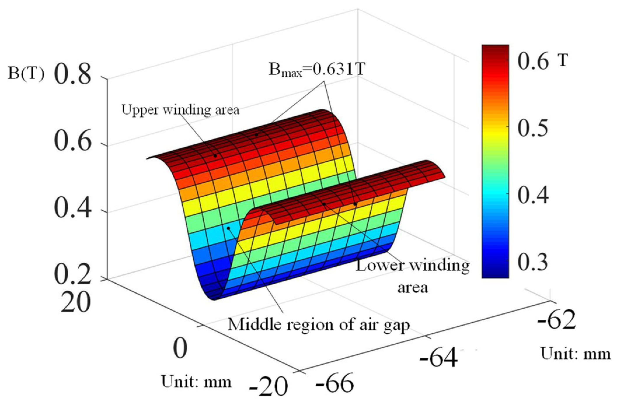
To extract the magnetic flux density in the winding air gap, the maximum magnetic flux density in the upper winding air gap is 0.6315 T, and the maximum magnetic flux density in the lower winding air gap is −0.6315 T. As the direction of the coil current is opposite in the two regions, the direction change of the magnet flux density will not affect the output force or the torque of the novel magnetic bearing.
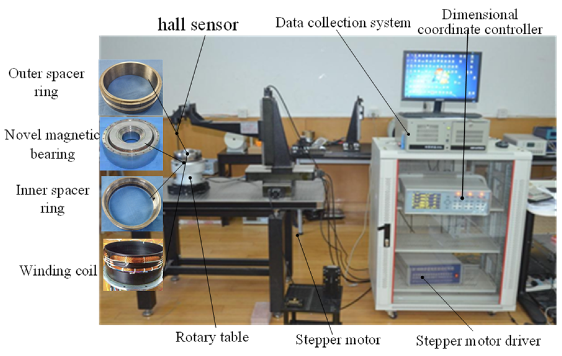
3.2. Experiment
Based on the calculation model and the mechanical structure, a prototype of the novel magnetic bearing was manufactured. The magnetic flux density in the winding region was experimentally measured by a magnetic density measuring machine. As shown in Figure 5, the magnetic bearing is fixed in a non-magnetic chuck. The magnetic density Hall sensor was adjusted by a stepper motor in the Z-axis direction of the measurement table to a different place of the winding area in the magnetic bearing. The experimental result is shown in Figure 6. It can be seen from the figure that the magnetic field at the air gap of the novel Lorentz magnetic bearing is symmetrically distributed, and the maximum magnetic flux density in the air gap area of the upper winding area is 0.631 T.
Table 1 is the comparison of the maximum magnetic flux density and its fluctuation in the winding area measured by three different experiments with reference [17]. It is shown that the maximum magnetic flux density in the winding area increased and its fluctuation reduced to 0.585% as the existence of the double second air gap disappeared.
Table 1 shows the comparison of the maximum magnetic flux density and its fluctuation in the winding area measured by three different experiments with reference [17]. It can be seen from Table 1 that the maximum magnetic field density in the winding area is significantly increased and the magnetic density fluctuation rate is reduced to 0.585% in the novel Lorentz magnetic bearing, which is 0.615 T and 0.9% in reference [17].
4. Conclusions
In this paper, a novel Lorentz magnetic bearing was designed. With the double second air gap, it overcomes the disadvantage of large air gap flux density fluctuation. It has a maximum magnetic flux density of 0.631 T, which is approximately 0.615 T in a traditional Lorentz magnetic bearing. The magnetic density fluctuation rate is only approximately 0.56%. The mathematical model to calculate the air gap magnetic field intensity in the Lorentz magnetic bearing winding area is established. A prototype of the novel magnetic bearing was manufactured, and the experiment of the magnetic density was carried out. The maximum magnetic field density is 0.631 T, which was measured in the experiment. The experimental result is consistent with the simulation result, which verifies the effectiveness of the double second air gap.
Author Contributions
Conceptualization, S.C. and P.N.; methodology, S.C.; software, W.W.; validation, S.C., J.L. and Q.L.; formal analysis, S.S.; investigation, S.S.; resources, P.N.; data curation, S.C.; writing—original draft preparation, S.C.; writing—review and editing, S.C.; visualization, S.S.; supervision, Q.L.; project administration, P.N.; funding acquisition, Q.L. All authors have read and agreed to the published version of the manuscript.
Funding
Research was funded by the Beijing Natural Fund (grant nos. 3212004) and Award Cultivation Foundation from the Beijing Institute of Petrochemical Technology (grant nos. BIPTACF-007). The research was funded by the Joint Doctoral Program of Beijing Institute of Petrochemical Technology.
Institutional Review Board Statement
Not applicable.
Informed Consent Statement
Not applicable.
Data Availability Statement
Not applicable.
Conflicts of Interest
The authors declare no conflict of interest.
References
- Zhu, X.; Chen, J.; Zhu, Z.H. Adaptive learning observer for spacecraft attitude control with actuator fault. Aerosp. Sci. Technol. 2021, 108, 106389. [Google Scholar] [CrossRef]
- Deng, R.Q.; Zhao, Y.; Fang, J.C.; Zhang, D.C. Disturbance characteristics analysis of magnetically suspended and mechanical flywheel. J. Astronaut. 2016, 37, 917–923. [Google Scholar]
- Tang, J.; Zhao, X.; Wang, Y.; Cui, X. Adaptive neural network control for rotor’s stable suspension of Vernier-gimballing magnetically suspended flywheel. Proc. Inst. Mech. Eng. 2019, 233, 1017–1029. [Google Scholar] [CrossRef]
- Peng, C.; Cai, K.; Deng, Z.; Li, K. Vibration Torque Suppression for Magnetically Suspended Flywheel Using Improved Synchronous Rotating Frame Transformation. Shock. Vib. 2019, 2019, 3607164. [Google Scholar] [CrossRef]
- Liu, B.; Fang, J.; Liu, G.; Fan, Y. Unbalance vibration control and experiment research of magnetically suspended flywheels. J. Mech. Eng. 2010, 46, 188–194. [Google Scholar] [CrossRef]
- Xia, C.; Cai, Y.; Ren, Y. Stable control method for rotor tilt channel in magnetically suspended control and sensing gyro. Control. Theory Appl. 2020, 7, 1535–1543. [Google Scholar]
- Xiang, B.; Tang, J. Suspension and titling of vernier-gimballing magnetically suspended flywheel with conical magnetic bearing and Lorentz magnetic bearing. Mechatronics 2015, 28, 46–54. [Google Scholar] [CrossRef]
- Foote, S.A.; Grindeland, D.B. Model QA3000 Q-Flex accelerometer high performance test results. IEEE Aerosp. Electron. Syst. Mag. 1992, 7, 59–67. [Google Scholar] [CrossRef]
- Xu, G.P.; Tian, W.F.; Qian, L. EMD- and SVM-based temperature drift modeling and compensation for a dynamically tuned gyroscope (DTG). Mech. Syst. Signal Process. 2007, 21, 3182–3188. [Google Scholar] [CrossRef]
- Chassoulier, D.; Chillet, C.; Delamare, J.; Yonnet, J.-P. Magnetic Centering Bearing with High-Amplitude Tilt Control. U.S. Patent 6384500B1, 7 May 2002. [Google Scholar]
- Gerlach, B.; Ehinger, M.; Knut Raue, H.; Seiler, R. Gimballing magnetic bearing reaction wheel with digital controller. In Proceedings of the 6th International ESA Conference on Guidance, Navigation and Control Systems, San Francisco, CA, USA, 17–20 October 2005; pp. 1–6. [Google Scholar]
- Wei, Z.; Zu, J.W. Analysis of Nonlinear Dynamics for a Rotor-Active Magnetic Bearing System with Time-Varying Stiffness: Part I—Formulation and Local Bifurcations. Int. J. Non-Linear Mech. 2003, 116, 631–640. [Google Scholar]
- Xu, G.; Cai, Y.; Yuan, R.; Xin, C.; Liu, Q. Application of a New Lorentz Force-type Magnetic Bearing in Tilting Control for Magnetically Suspended Control & Sensitive Gyroscope with Cross Sliding Mode Control. J. Aerosp. Technol. Manag. 2017, 59, 107–109. [Google Scholar]
- Yin, Z.; Cai, Y.; Wang, W.; Ren, Y. A lorentz force magnetic bearing design method with composite magnetic steel and siperimposed magnetic field. J. Astronaut. 2018, 39, 56–64. [Google Scholar]
- Liu, Q.; Zhao, Y.; Wang, W.; Wu, B.; Hu, D. An Implicit Lorentz Force Deflected Magnetic Bearing with U-Shaped Polymagnetic Effect. CN Patent 106763187A, 31 May 2017. [Google Scholar]
- Xu, G.; Cai, Y.; Ren, Y.; Fan, Y.; Sun, J.; Zhao, H. Design and analysis on uniformity of magnetic flux density in Lorentz force-type magnetic bearing. J. Beijing Univ. Aeronaut. Astronaut. 2017, 43, 559–566. [Google Scholar]
- Liu, Q.; Wang, Q.; Li, H.; Peng, C.; Xu, K.; Ren, Y. Improved design of Lorentz force-type magnetic bearings for magnetically suspended gimballing flywheels. J. Power Electron. 2021, 21, 603–615. [Google Scholar] [CrossRef]
Figure 1.
The magnetic circuit direction and structure of the novel Lorentzian magnetic bearing. (a) Magnetic circuit direction, (b) Structure of the novel bearing.
Figure 1.
The magnetic circuit direction and structure of the novel Lorentzian magnetic bearing. (a) Magnetic circuit direction, (b) Structure of the novel bearing.

Figure 2.
Magnetic reluctance classification.

Figure 3.
Magnetic bearing circuit diagram.

Figure 4.
Novel magnetic bearing magnetic density cloud map.

Figure 5.
Experiment of the measurement magnetic density.

Figure 6.
Result of the magnetic flux density measurement.


Table 1.
Magnetic density comparison.
| Reference [17] | Lorentz Magnetic Bearing | |
|---|---|---|
| Maximum B | 0.615 T | 0.631 T |
| Fluctuation | 0.9% | 0.58% |
Publisher’s Note: MDPI stays neutral with regard to jurisdictional claims in published maps and institutional affiliations. |
© 2022 by the authors. Licensee MDPI, Basel, Switzerland. This article is an open access article distributed under the terms and conditions of the Creative Commons Attribution (CC BY) license (https://creativecommons.org/licenses/by/4.0/).
Share and Cite
MDPI and ACS Style
Cao, S.; Niu, P.; Wang, W.; Liu, Q.; Li, J.; Sheng, S. Magnetic Circuit Design and Experiment of Novel Lorentz Magnetic Bearing with Double Air Gap. Energies 2022, 15, 4830. https://0-doi-org.brum.beds.ac.uk/10.3390/en15134830
AMA Style
Cao S, Niu P, Wang W, Liu Q, Li J, Sheng S. Magnetic Circuit Design and Experiment of Novel Lorentz Magnetic Bearing with Double Air Gap. Energies. 2022; 15(13):4830. https://0-doi-org.brum.beds.ac.uk/10.3390/en15134830
Chicago/Turabian StyleCao, Shinan, Pingjuan Niu, Wei Wang, Qiang Liu, Jing Li, and Sha Sheng. 2022. "Magnetic Circuit Design and Experiment of Novel Lorentz Magnetic Bearing with Double Air Gap" Energies 15, no. 13: 4830. https://0-doi-org.brum.beds.ac.uk/10.3390/en15134830
Note that from the first issue of 2016, this journal uses article numbers instead of page numbers. See further details here.