
Low–Harmonic Control Strategy of a Dual Three–Phase Synchronous Reluctance Motor Based on Three–Vector Synthesis


School of Electrical and Information Engineering, Jiangsu University, Xuefu Road 301, Zhenjiang 212013, China
*
Author to whom correspondence should be addressed.
Energies 2022, 15(17), 6350; https://0-doi-org.brum.beds.ac.uk/10.3390/en15176350
Submission received: 1 August 2022
/
Revised: 28 August 2022
/
Accepted: 29 August 2022
/
Published: 31 August 2022
(This article belongs to the Special Issue Design and Control of Flywheel Energy Storage Systems)
Abstract
:Dual three–phase synchronous reluctance motors (DTP–SynRM) have the advantages of simple structure, high power density, fast dynamic response, and small torque ripple, and have broad application prospects in flywheel batteries. However, the synchronous reluctance motor has no permanent magnet, and the inductance value will change with the current change in actual operation. Direct torque control (DTC) is more suitable for the control strategy of dual three–phase synchronous reluctance motors because of its low dependence on motor parameters. However, traditional direct torque control uses a large vector control motor within one control period, which can not suppress the inherent 5th and 7th current harmonics in the motor. A new harmonic suppression method is proposed in this paper: that is, using a low harmonic vector to replace a large vector in traditional direct torque control, which can be synthesized by adjusting the action time and order of three adjacent large vectors within one control period. Through this improvement, torque control can have a harmonic suppression effect. The three vector synthesis method can make full use of the existing space voltage vector, and to adapt to different working conditions, two synthesis methods of switching frequency reduction and constant torque response are proposed. An improved direct torque control strategy is obtained by optimizing the design of the switch table using a new vector synthesis method. Finally, the suppression effect of traditional DTC and improved DTC on current harmonics is compared and analyzed. The results show that the direct torque control with low harmonic vector can suppress the harmonic current in x–y subspace, and the current harmonic content is greatly reduced.
1. Introduction
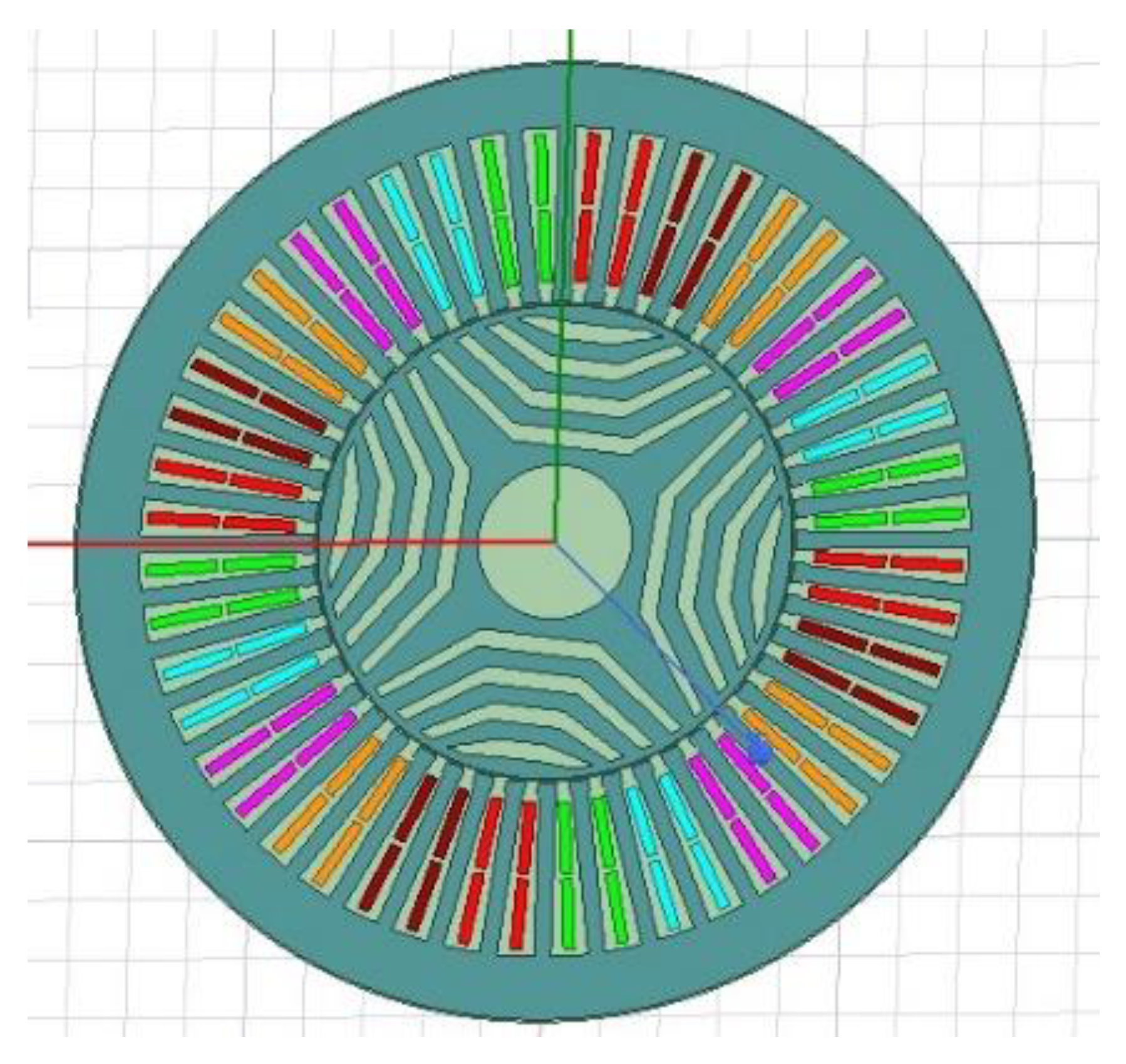
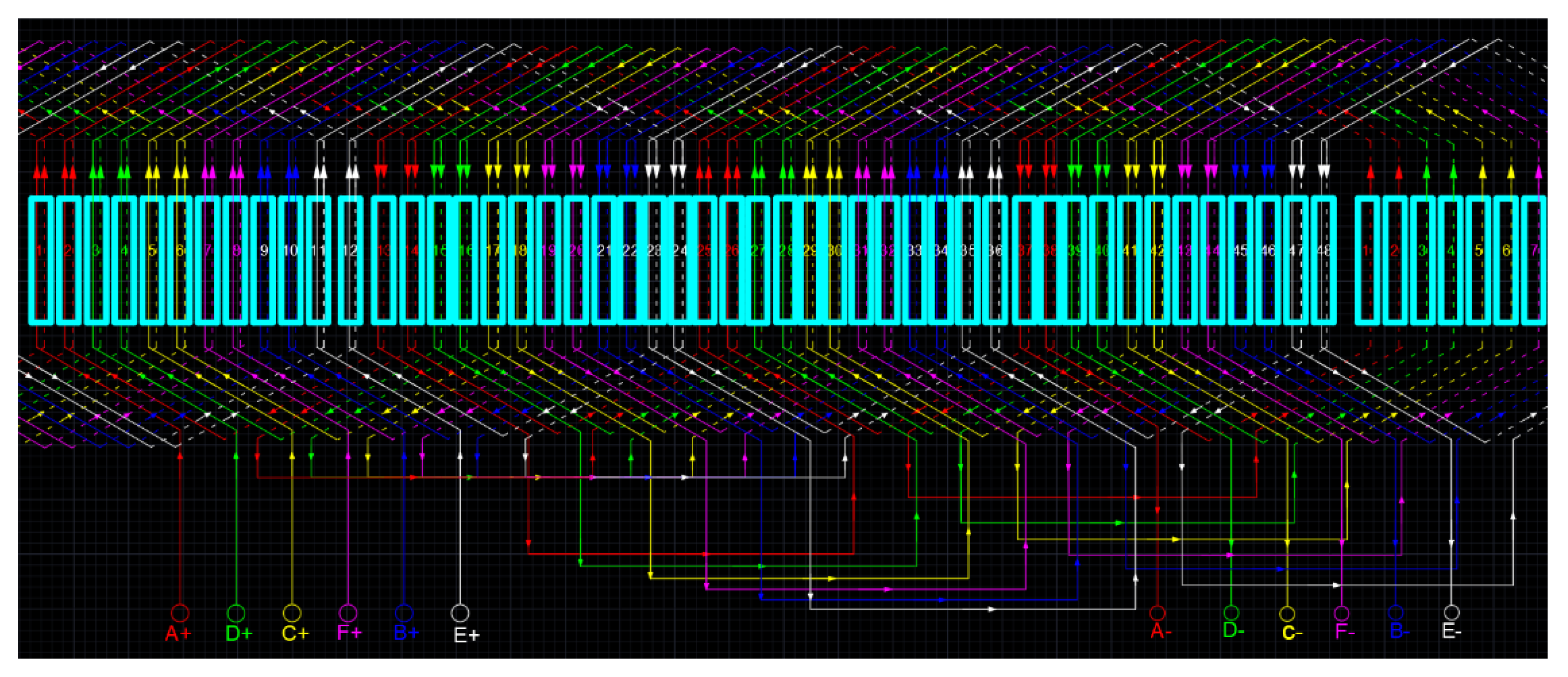
Electric vehicles have the advantages of no pollution, low noise and high efficiency [1], but the power batteries and fuel cells used in electric vehicles have low power density, poor regenerative braking effect, low safety factor, and short cycle life defects [2], which hinder the further promotion of electric vehicles. The flywheel battery has the advantages of no pollution, fast response, high transmission efficiency, and high power density [3]. In combination with high specific energy batteries, it can make up for the shortcomings of traditional power batteries and further improve the performance of electric vehicles. The DTP–SynRM is also called a six–phase synchronous reluctance motor. The stator and rotor magnetic core structure is shown in Figure 1. The motor winding design adopts a double–layer winding structure, as shown in Figure 2. The rotor is a multi–layer magnetic barrier structure without permanent magnets. Its main advantages are simple structure, high reliability, small torque ripple and high power density [4]. The DTP–SynRM can realize low–voltage and high–power operation [5], which overcomes the shortcoming of the permanent magnet synchronous motor that produces a large flywheel standby loss and the shortcoming of the switched reluctance motor’s large torque ripple. It can improve the overall efficiency and dynamic response performance of the flywheel battery, and is suitable as a flywheel motor. Synchronous reluctance motors have been used in flywheel batteries, which have obvious advantages over asynchronous motors and show application prospects [6].
The DTP–SynRM selected in this paper has an asymmetrical winding structure, and the 5th and 7th harmonic magnetomotive forces during operation are cancelled to generate the 5th and 7th current harmonics [7,8]. This harmonic problem is inherent to the asymmetric winding structure and can only be compensated by a control strategy. At present, the control strategies for dual three–phase motors mainly include vector control [9,10,11,12] and direct torque control [13,14,15,16,17]. Because there is no permanent magnet on the rotor of a dual three–phase synchronous reluctance motor, the magnetic saturation of the d–axis has a great influence on its inductance; its value will decrease with the increase in current. By contrast, direct torque control is less affected by the variation in motor parameters. Therefore, it is more suitable for dual three–phase synchronous reluctance motors.
Compared with the three–phase motor, the dual three–phase motor has 64 space voltage vectors, which have the characteristics of multi–dimensional sub–planes. The combination of space vectors is more flexible, which helps to reduce flux and torque pulsation. The direct torque control in Refs. [13,14] is only controlled in the fundamental wavelet plane, which has the problem of a large harmonic component of current. Literature [15] introduced a disturbance observer to suppress harmonics, but the observer design relies on the mathematical model of the motor. In Refs. [16,17], the closed–loop strategy of SVPWM is used to suppress harmonics, and the calculation amount and complexity of the system are greatly increased. Refs. [18,19,20] proposed a harmonic suppression strategy for a dual–phase permanent magnet synchronous machine (PMSM) based on a proportional resonance controller and quasi–proportional resonance (QPR) cascade PI, but the control system is too complex. Refs. [21,22] use current predictive control to suppress harmonics, but the control effect depends on an accurate discrete mathematical model.
Although the above control strategy suppresses the harmonics, it does not consider the influence of the improved scheme on the dynamic response of the motor. At the same time, it increases the system complexity and the amount of calculation, depends on the motor parameters, and loses the advantages of simple structure, high reliability, and little influence from motor parameters. In this paper, an improved direct torque control strategy is proposed, which retains the advantages of simple structure and good dynamic performance while suppressing the stator current harmonics. By optimizing the switching table and making full use of the space voltage vector, both the harmonic suppression effect and the dynamic response performance of the motor are considered. Improved schemes suitable for high–speed and high–performance control are proposed, respectively.
The structure of this article is as follows. The second section describes the mathematical model of the motor using the vector space decoupling (VSD) technology and analyzes the mechanism of harmonic generation. The third section introduces the traditional DTC scheme. In Section 4, by analyzing the influence of inverter vectors on torque generation and stator flux linkage in different subspaces, an improved switching table and vector synthesis scheme are proposed. In Section 5, simulation results are given to verify the effectiveness of the proposed strategy. In Section 6, the effectiveness of the proposed harmonic suppression strategy is verified by experiments. Finally, the seventh part summarizes the conclusion.
2. Harmonic Mechanism Analysis
The DTP–SynRM is equivalent to a six–dimensional system that has the characteristics of high–order, nonlinear and strong coupling. By employing the VSD technique, the original six–dimensional system can be decomposed into three two–dimensional uncoupled subspaces: α–β, x–y, and o1–o2. The fundamental components of the machine variables (voltage, current, or flux) and the harmonics of order k = 12m ± 1 (m = 1, 2, 3, …) are mapped to the α–β subspace, while the harmonics with k = 6m ± 1 (m = 1, 3, 5, …) are transformed into the x–y subspace. The zero–sequences with k = 3m (m = 1, 3, 5, …) are located in the o1–o2 subspace to form the classical zero sequence components.
For ease of study, the motor windings are assumed to have a sinusoidal distribution, ignoring magnetic saturation, leakage inductance, and core losses. At this time, the DTP–SynRM model in the rotating coordinate system can be described. The voltage equation in the α–β subspace is
The voltage equation in the x–y subspace is
The electromagnetic torque is
The mechanical equation is
where Ld, Lq are d–axis and q–axis inductances. R is the stator resistance. pn is the number of pole pairs. ωe is the electrical angular velocity. Te is the electromagnetic torque. TL is the load torque. J is the moment of inertia. B is the viscous friction coefficient.
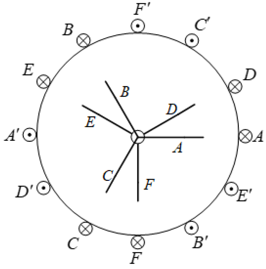
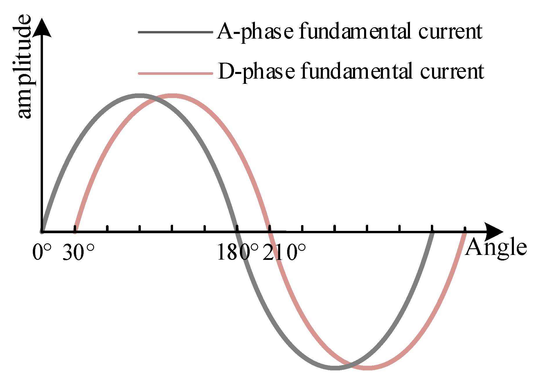
The DTP–SynRM with phase shift of 30° is adopted in this paper. The neutral point isolation of two sets of three–phase windings has a difference of 30° in space, as shown in Figure 3.
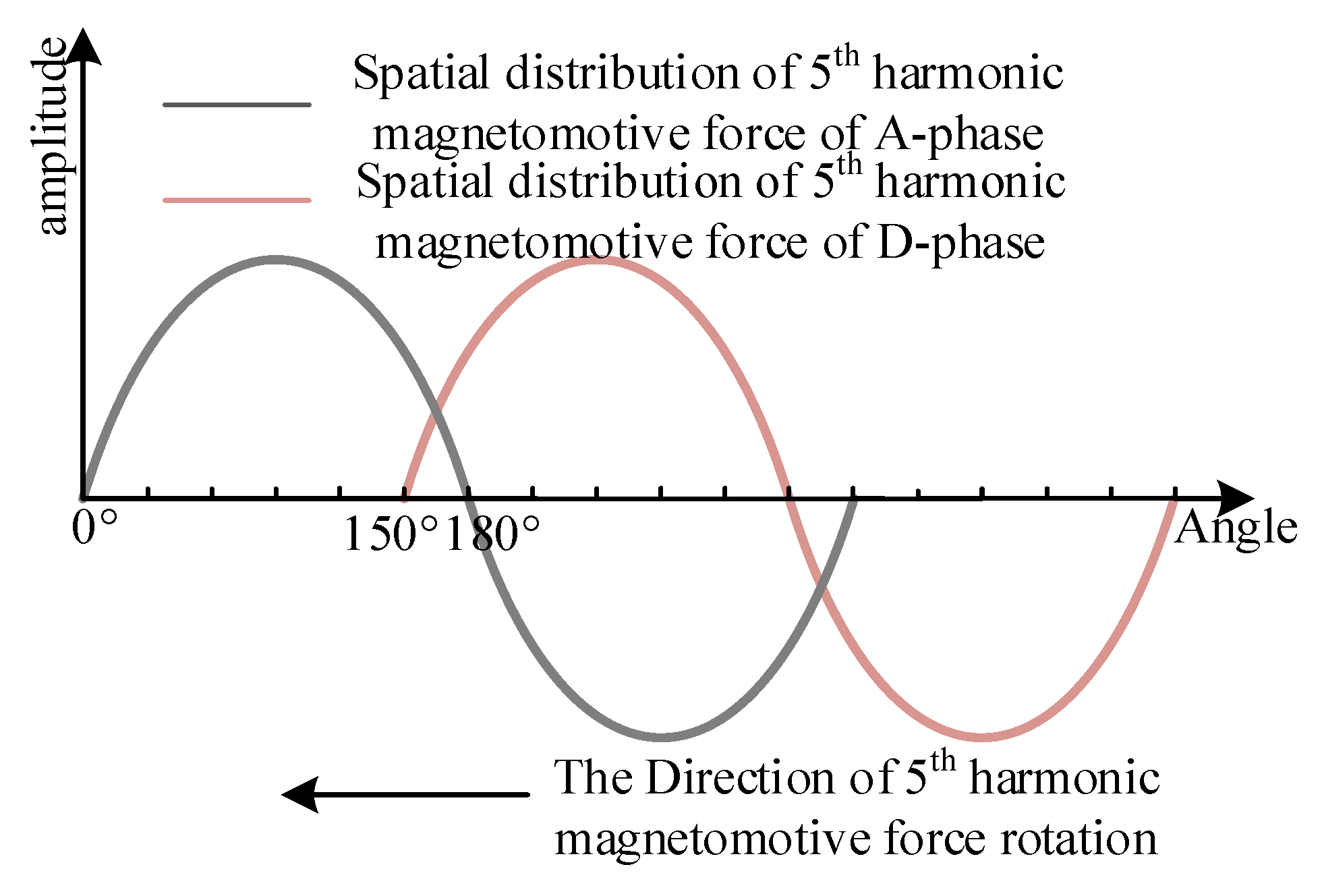
The spatial distribution of the 5th harmonic magnetomotive force in the motor differs by 150° electrical angle, as shown in Figure 4. Because the phase difference between the two sets of winding currents of the double three–phase motor is 30°, the space–time distribution of the 5th harmonic magnetomotive forces is 180° and offsets each other. Similarly, the phase difference in the spatial distribution of the 7th harmonic magnetomotive force, which is opposite to the rotation direction of the 5th harmonic magnetomotive force, is also a 150° electrical angle. The phase difference of the two sets of winding currents of the double three–phase motor is 30°, and the electrical angle also causes the space–time distribution difference of the 7th harmonic magnetomotive forces to be 180° and offset each other. In the DTP–SynRM, there will be no 5th and 7th harmonic rotating magnetic field, corresponding to the x–y subspace; the 5th and 7th harmonic impedance is very small. However, there are the 5th and 7th harmonics in the phase voltage of the winding, which will make the stator current of the motor contain a large number of 5th and 7th harmonics. These harmonic currents will cause additional losses to reduce the overall operating efficiency of the flywheel battery.
3. Traditional DTC
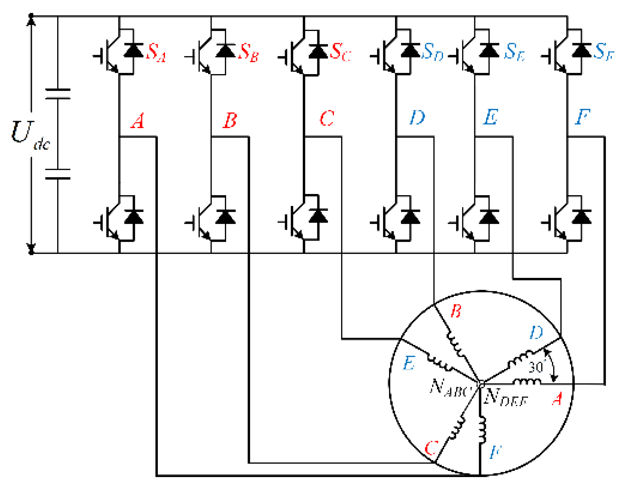
In this paper, a six–phase voltage source inverter is used to control the DTP–SynRM. The two sets of three–phase windings of the motor, which are respectively denoted as ABC and DEF, are spaced apart by 30° electrical angles, as shown in Figure 5.
The six–phase inverter, which is rich in control resources, has 64 space voltage vectors. Coordinate transformation (5) can be used to decouple the vector space and decompose the voltage vector of the dual three–phase motor into three mutually orthogonal subspaces: α–β, x–y, and o1–o2. The α–β subspace is called the fundamental wave subspace, and the corresponding component forms a rotating magnetomotive force in the air gap to participate in electromechanical energy conversion. The x–y subspace is called the harmonic subspace, and the corresponding components are 6k ± 1 (k = 1, 3, 5…) harmonic components, which do not generate electromagnetic torque. The harmonic content of the current is less when the component of the harmonic subspace is smaller. The o1–o2 subspace is called the zero sequence subspace. When the inverter adopts the neutral point isolation connection method in Figure 5, the component mapped onto the zero–sequence subspace is zero.
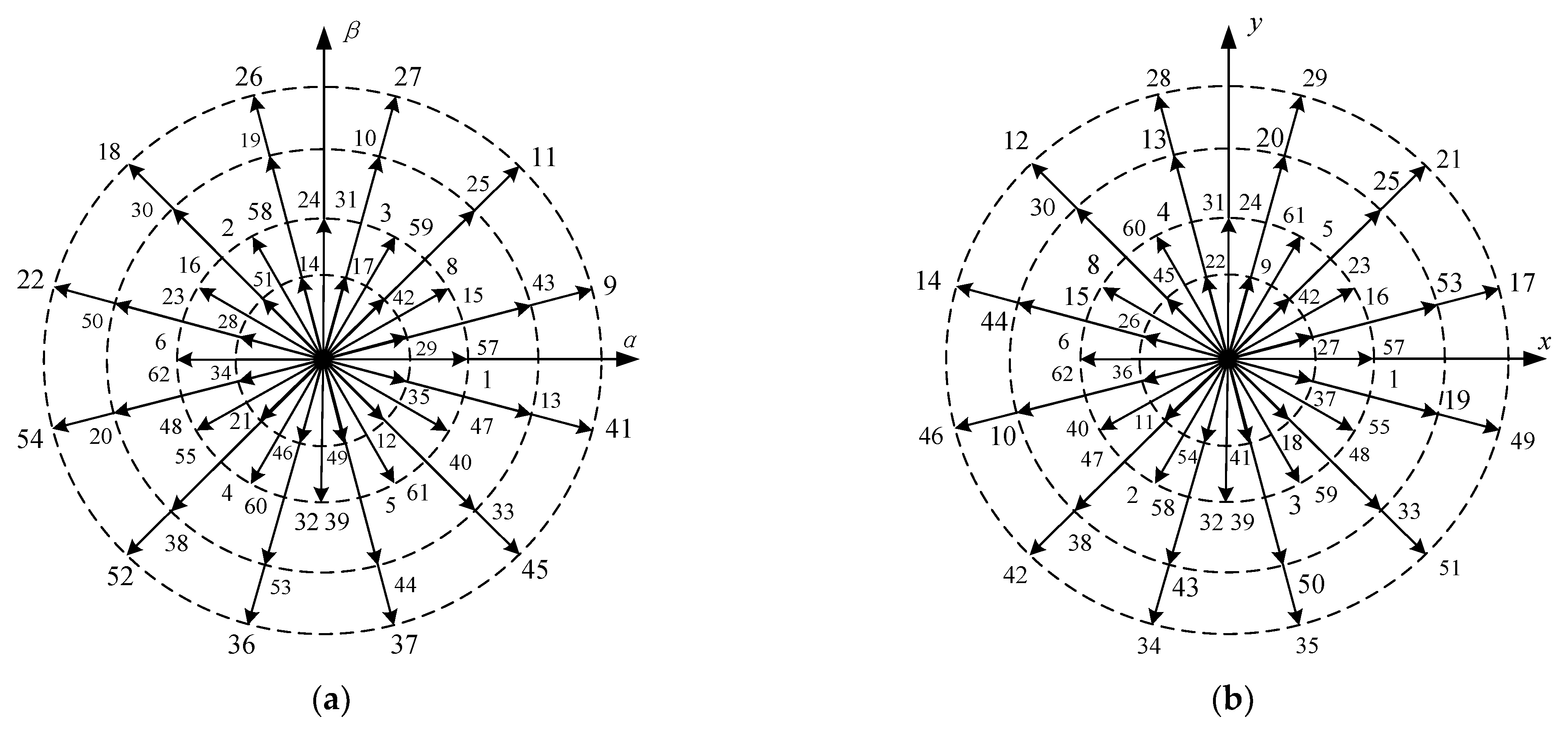
After decoupling the vector space of DTP–SynRM used in the current study, the 64 space voltage vectors are mapped onto the fundamental wave and harmonic subspaces, as shown in Figure 4 and Figure 6. The space voltage vector in each subspace contains 60 non–zero vectors and 4 zero vectors. The 60 nonzero vectors can be divided into 4 groups in accordance with their amplitude: large, medium, original, and small vectors. Each space voltage vector is numbered with a six–bit binary number converted into a decimal number, i.e., SF, SE, SD, SC, SB, and SA, from high to low. For each bit, “1” indicates that the upper bridge arm is turned on, while “0” indicates that the lower bridge arm is turned on. For example, when the A and D two–phase upper bridge arms and the remaining four–phase lower bridge arms are turned on, the corresponding binary number is 001001, which is converted into a decimal number of 9. The latter is space voltage vector 9 in Figure 7.
A one–to–one correspondence exists between the 64 space voltage vectors in the fundamental and harmonic subspaces. The 12 outermost large vectors in the fundamental subspace correspond to the 12 small vectors in the harmonic subspace. Suppose that the angle between the 12 large vectors of the fundamental wave subspace and the α–axis is θ1 and the angle between the corresponding vector and the x–axis in the harmonic subspace of this vector is θ2. Then, θ2 = 5θ1. For example, the angle between space voltage vector 9 and the α–axis is 15° and the angle between vector 9 and the x–axis in the harmonic subspace is 75°, as shown in Figure 7.
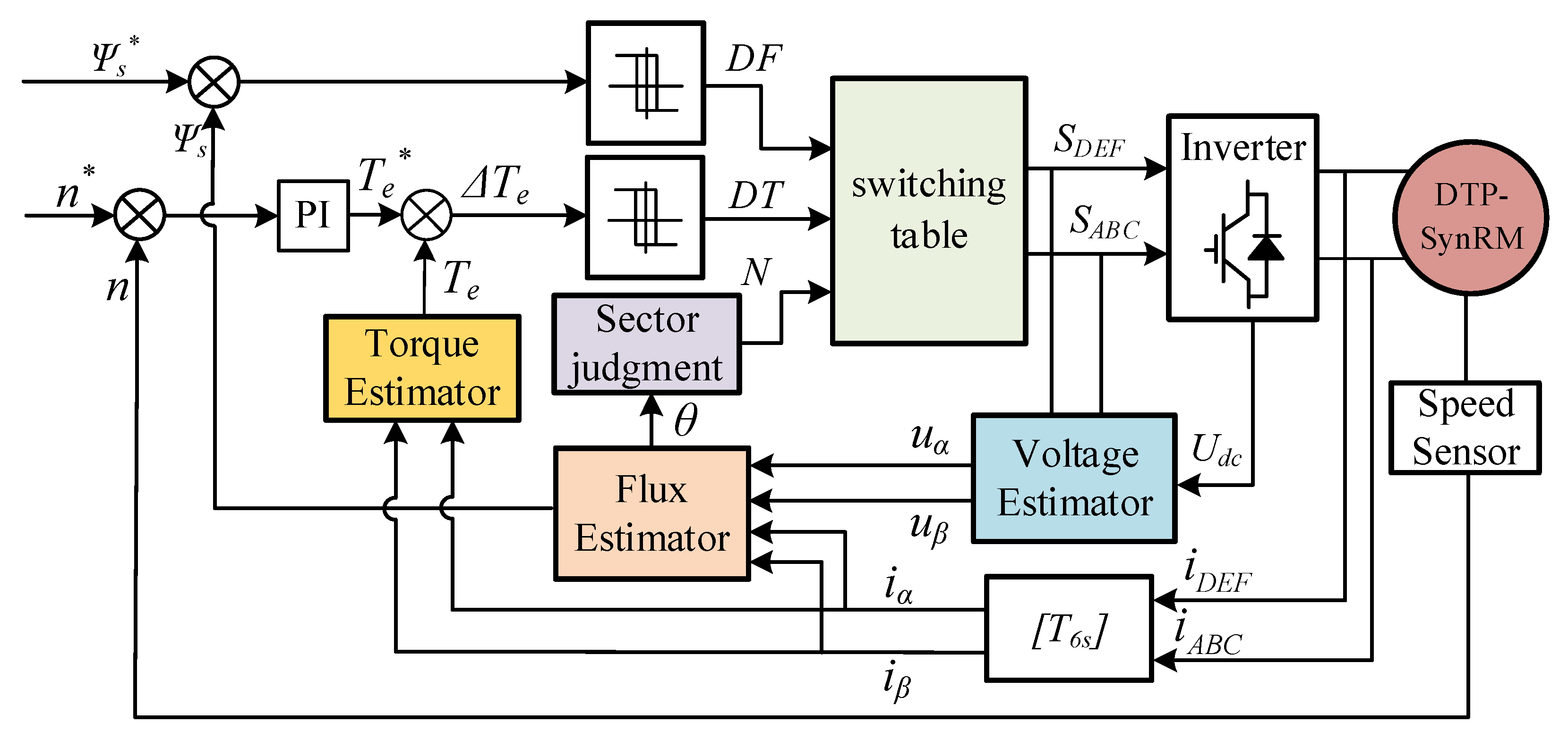
In traditional DTC, only one vector control motor is selected in each case, and it is mapped onto a small vector in the harmonic subspace. However, harmonic voltages caused by small vectors also generate large harmonic currents due to the small harmonic impedance in the harmonic subspace of a DTP–SynRM. The DTC of the DTP–SynRM includes modules, such as sector judgment, flux estimator, torque estimator, and switch table design. The principle block diagram is depicted in Figure 8.
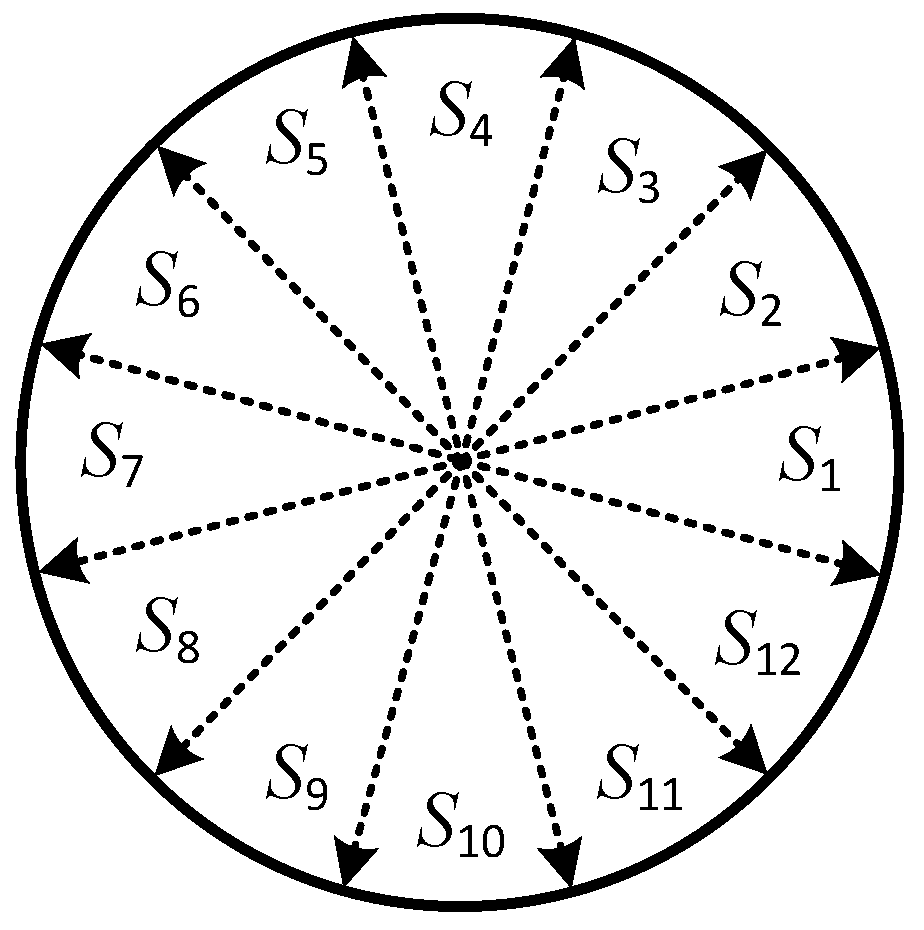
In this paper, 12 large vectors are divided into 12 sectors, as shown in Figure 9. This method can keep the control effect of torque and flux linkage unchanged for each vector in one sector.
The stator flux linkage is calculated by the back EMF integral method, which can be expressed as
The torque is calculated as
where t is sampling period, Usα and Usβ are the stator voltage components of the α–β subspace, isα and isβ are the stator current components of the α–β subspace, ψs is flux observation amplitude, φ is stator flux position angle, ψsα and ψsβ are flux linkage estimate, iα and iβ are current estimate, and np is the pole–pairs of motor.
After the difference between the estimated flux and torque and the given value, the hysteresis comparator is input to obtain the torque state value DT and the flux state value DF. Traditional DTC selects an appropriate large vector through three variables: state value DT, state value DF and sector number n. The advantage of using a large vector is that the DC voltage is highly utilized and the amplitude of the harmonic vector mapped to the harmonic subspace is small.
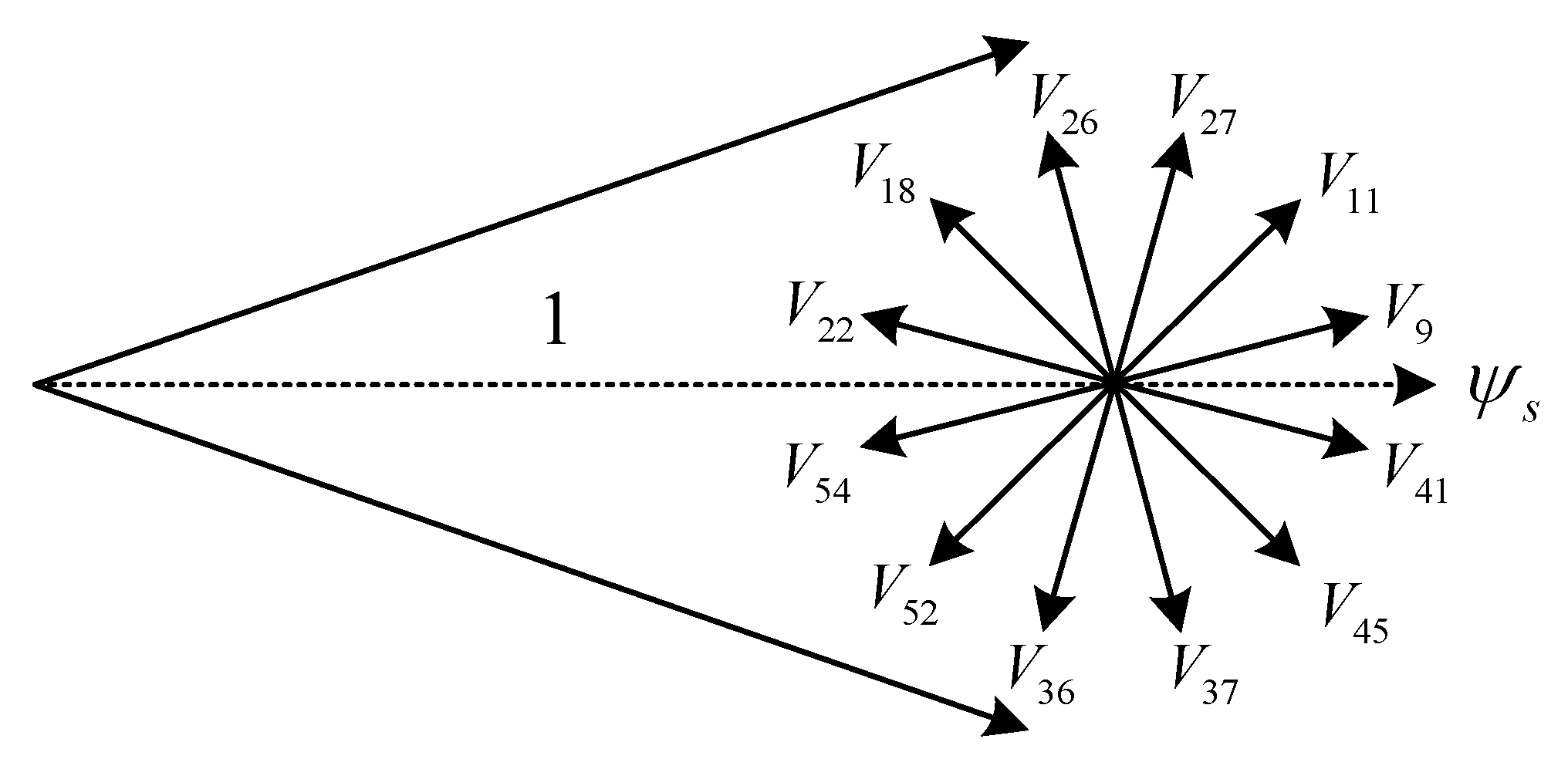
Presenting sector 1 as an example, counterclockwise is selected as the positive direction of motor rotation, and the direction outside the circle is the positive direction of flux increase. In sector 1, if the torque and flux increase at the same time, the space voltage vectors that can be selected are V9, V11 and V27, as shown in Figure 10.
The difference between the three vectors is that the response speed is different. The smaller the projection length of the vector on the flux axis, the faster the response to the torque and the slower the response to the flux. In Figure 10, vector V27 has the fastest response to torque and the slowest response to flux linkage, and V9 has the slowest response to torque and the fastest response to flux linkage. The response speed of V11 is the middle value. To increase torque and reduce flux linkage, V26, V18 and V22 space voltage vectors can be selected, and the selection method for other cases is similar.
The control effect of space voltage vector on torque and flux linkage in 12 sectors is analyzed. Taking the fastest torque response as the selection standard of the same function vector, the traditional switch table shown in Table 1 can be obtained. The disadvantage of the switch table is that there are harmonic vectors in the harmonic subspace, and the motor has large 5th and 7th harmonics during operation, which increases the loss of the fly–wheel battery.
4. Improved DTC
The difference between the improved DTC and traditional DTC is that the control requirements in the fundamental and harmonic subspaces must be considered simultaneously. The current harmonics in improved DTC can be suppressed after the vector space is decoupled and when the selected space voltage vector can meet the torque and flux linkage control requirements in the fundamental wave subspace and can cancel each other after being mapped onto the harmonic subspace.
Presenting vectors V41, V9, and V11 as examples, the mapping of three adjacent large vectors in the fundamental wave subspace onto the harmonic subspace is illustrated in Figure 11. The mappings of vectors V41, V9, and V11 onto the harmonic subspace are v41, v9, and v11, respectively. v11 leads v9 by 150°, and v41 lags v9 by 150°. The components of the harmonic subspace can be cancelled by controlling the action time of the three vectors within one control period Ts.
Suppose that the action time of vector V9 is Tmid, and that of vectors V41 and V11 is Tsid. In accordance with the trigonometric function relationship, the component of the harmonic subspace is zero when (11) is satisfied. The action time of three adjacent vectors should also satisfy.
Thus, the action time of three adjacent vectors is
The low–harmonic control vectors of M1–M12 can be obtained, as shown in Table 2, by combining three adjacent vectors in accordance with the preceding method.
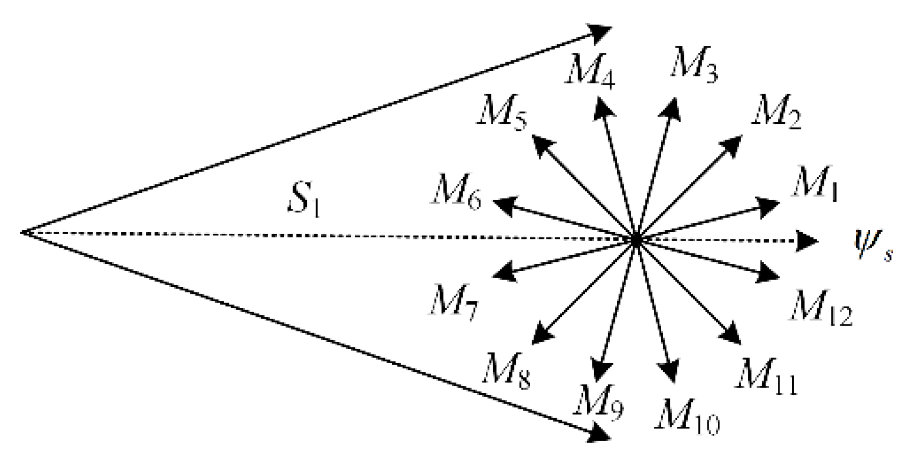
In accordance with the torque state value DT, the flux link state value DF, and the sector value n, the improved DTC selects a low–harmonic vector from the 12 low–harmonic vectors, which can control the motor without generating harmonics. Sector 1 is presented as an example; when the torque and flux linkage need to be increased at the same time, the optional vectors are M1, M2 and M3, as shown in Figure 12. In traditional DTC, the fastest torque response is taken as the standard, and the vector M3 is selected. Vector M3 is composed of vectors V11, V27 and V26. Vector V26 increases the torque but reduces the flux linkage, which cannot fully meet the control requirements.
Therefore, the improved DTC proposed in this paper takes the fast torque response as the standard, and M2 is selected. Vector M2 is composed of vectors V9, V11 and V27, all of which can fully meet the control requirements of torque and flux linkage. This method makes full use of the vectors with the same function but different response speed, which can not only meet the control requirements of the motor, but also realize the suppression of current harmonics. After analyzing all 12 sectors, the harmonic suppression switch table shown in Table 3 can be obtained.
Although the harmonic suppression switch table has been determined, the method of low–harmonic vector synthesis can also be optimized. The switching sequence diagram of each phase–switching device when synthesizing low–harmonic vectors can be drawn on the basis of Table 2.
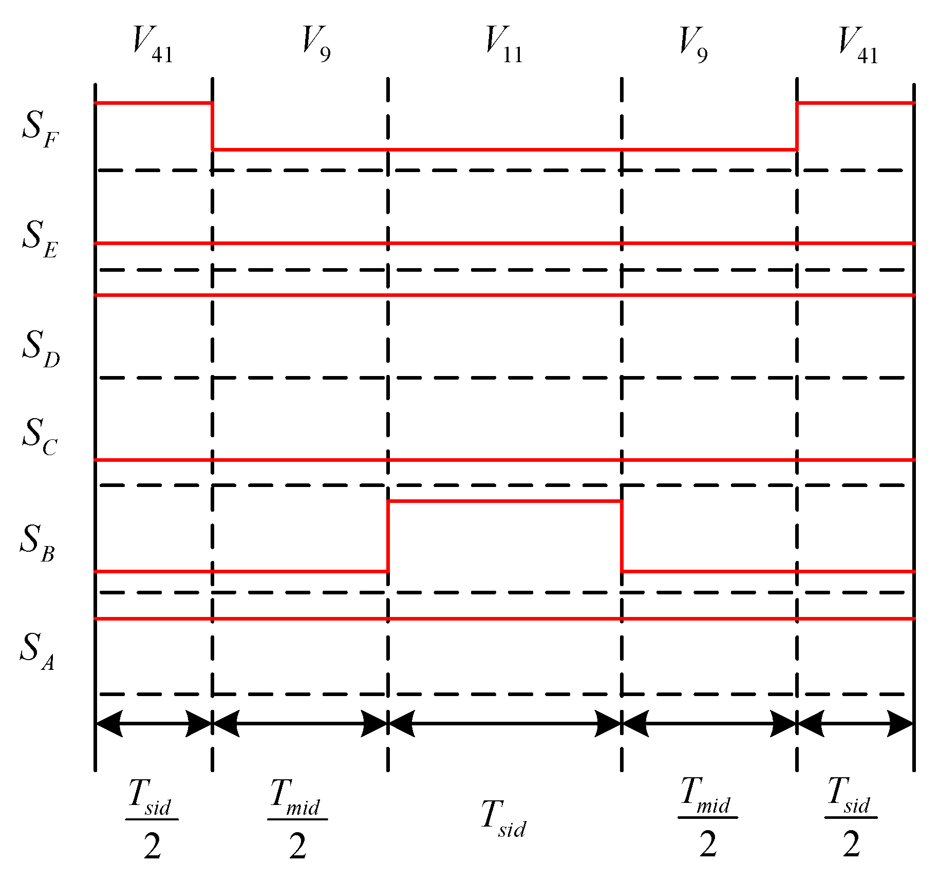
M1 is presented as an example, as shown in Figure 13. To reduce harmonics as much as possible, simultaneous changes in the switching states of the two phases should be avoided. Thus, partial vector action time is divided into two halves to make the output waveform symmetrical. The switching diagram of the switching sequence process of replacing V9 with M1 synthesized by V41, V9, and V11 is presented in Figure 13. The output of this scheme is a five–segment PWM wave, which is easier to implement by hardware than the seven–segment PWM. The 11 other low–harmonic vectors can also obtain the optimization scheme of switching frequency reduction.
To reduce the switching frequency of the device, the switching sequence in Figure 13 is adjusted to obtain the switching sequence shown in Figure 14. In the switching sequence of Figure 14, the switching frequency of phase B is reduced to half of the original.
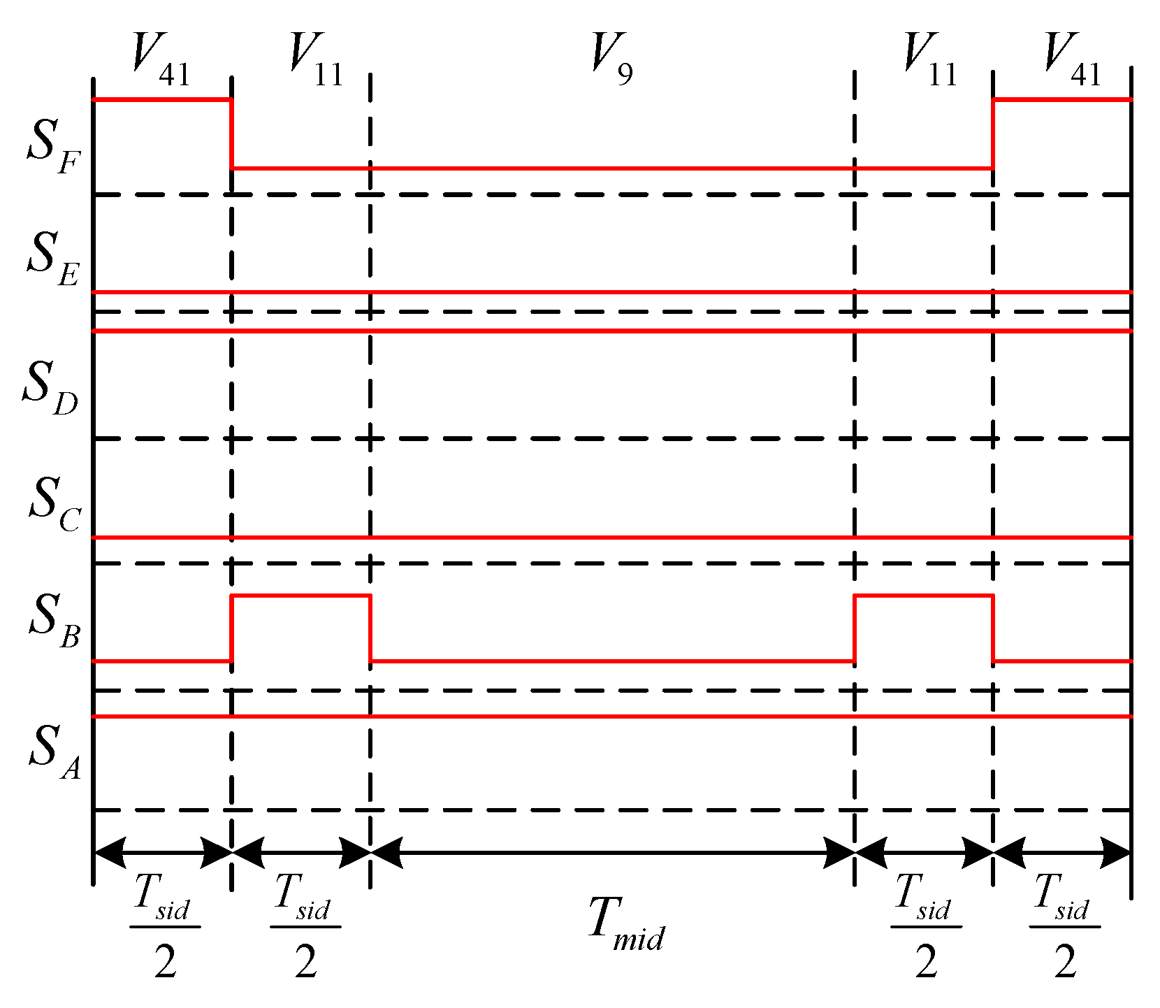
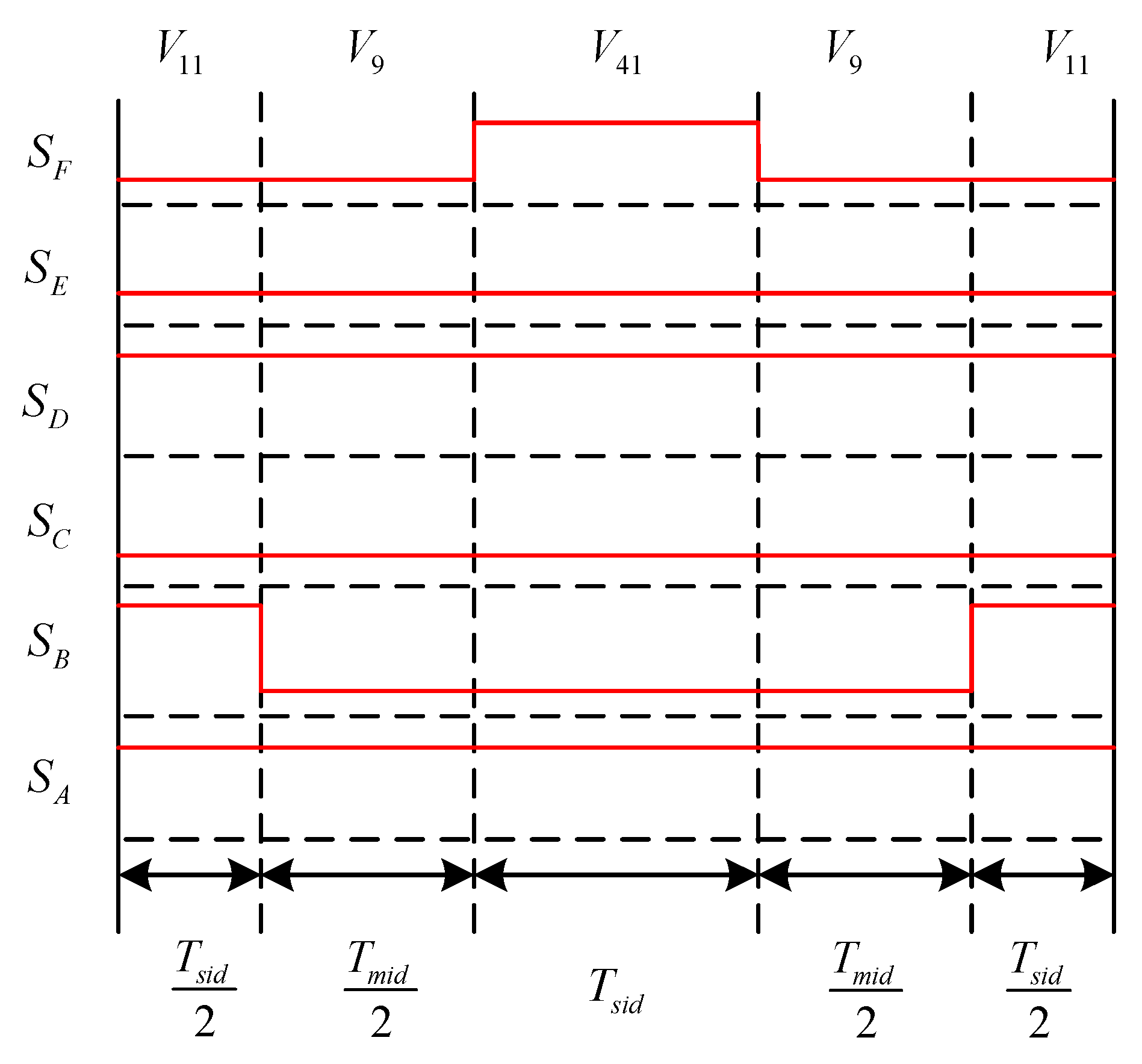
The switching sequence in Figure 14 uses the vector sequence V41, V9 and V11 when synthesizing M1. V41 has the slowest torque response speed, which will lead to the reduction of the torque response speed of the synthesized M1. Adjusting the vector order again yields the switch sequence synthesis table, as shown in Figure 15. In Figure 15, the vector sequence is V11, V9 and V41. V11 has the fastest response to torque, and the resultant M1 torque response speed remains unchanged. This avoids sacrificing torque performance to suppress harmonics. The 11 other low–harmonic vectors can also obtain the optimization scheme with constant torque response speed.
Therefore, two optimization schemes are proposed in this paper, namely the switching frequency reduction scheme and the torque response invariant scheme.
5. Simulation
To verify the effectiveness of the harmonic suppression strategy proposed in this study, a DTP–SynRM control system was built on the MATLAB platform. The parameters of the motor used in the simulation are shown in Table 4.
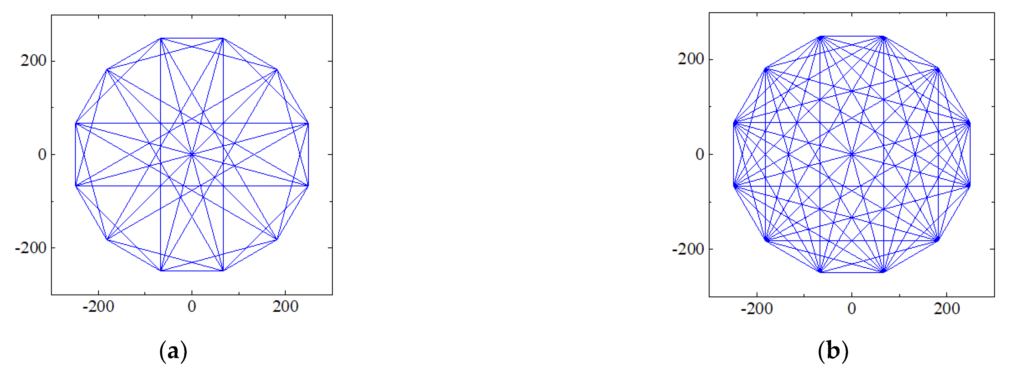
The voltage vector simulation of the DTC system of the DTP–SynRM is illustrated in Figure 16. After adopting the low–harmonic vector, the density of the voltage vector is three times that of the original, which verifies the feasibility of three–vector synthesis of the low–harmonic vector.
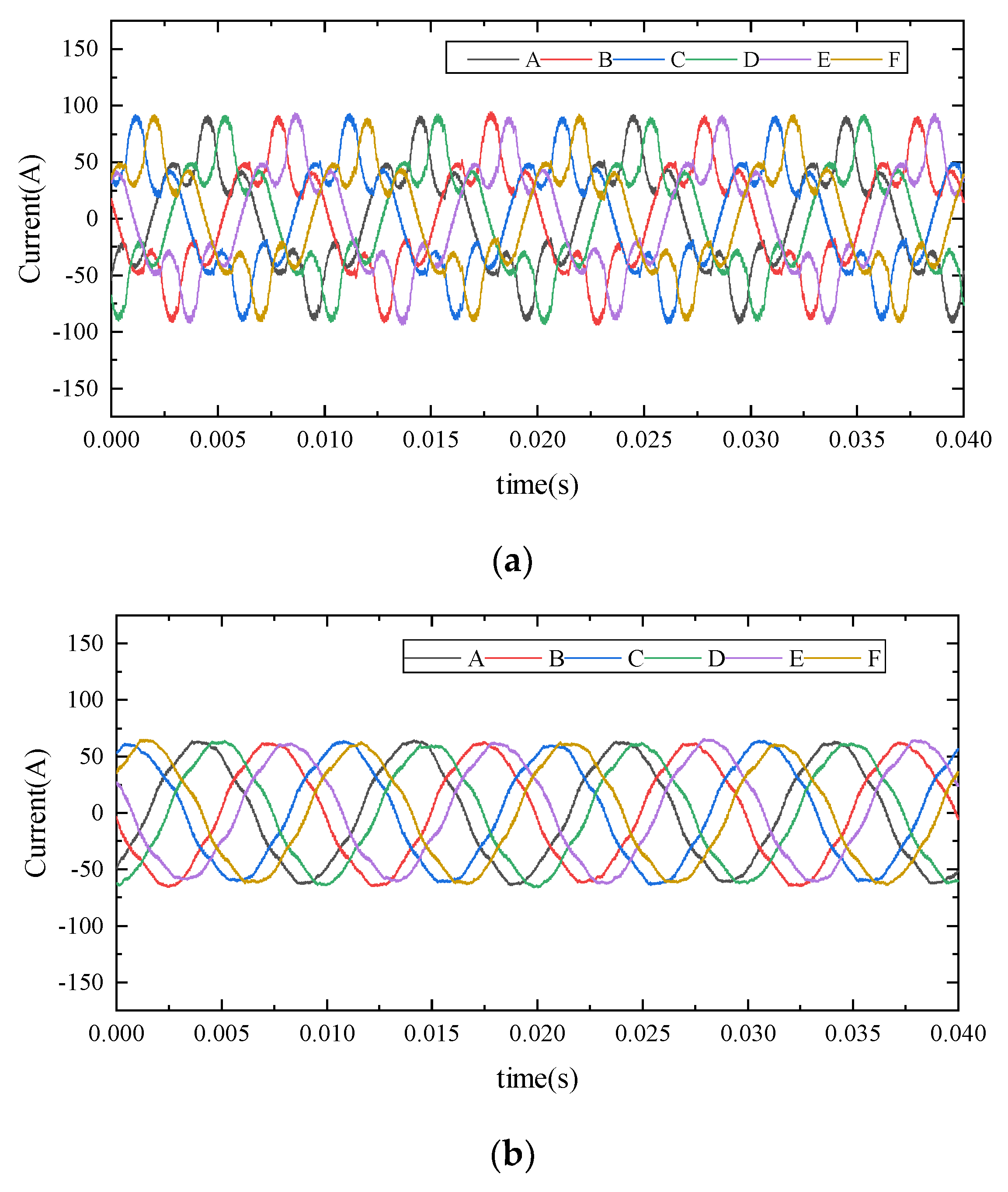
The six–phase current simulation of the DTP–SynRM’s DTC system is depicted in Figure 17. After adopting a low–harmonic vector, the current becomes closer to the sine wave.
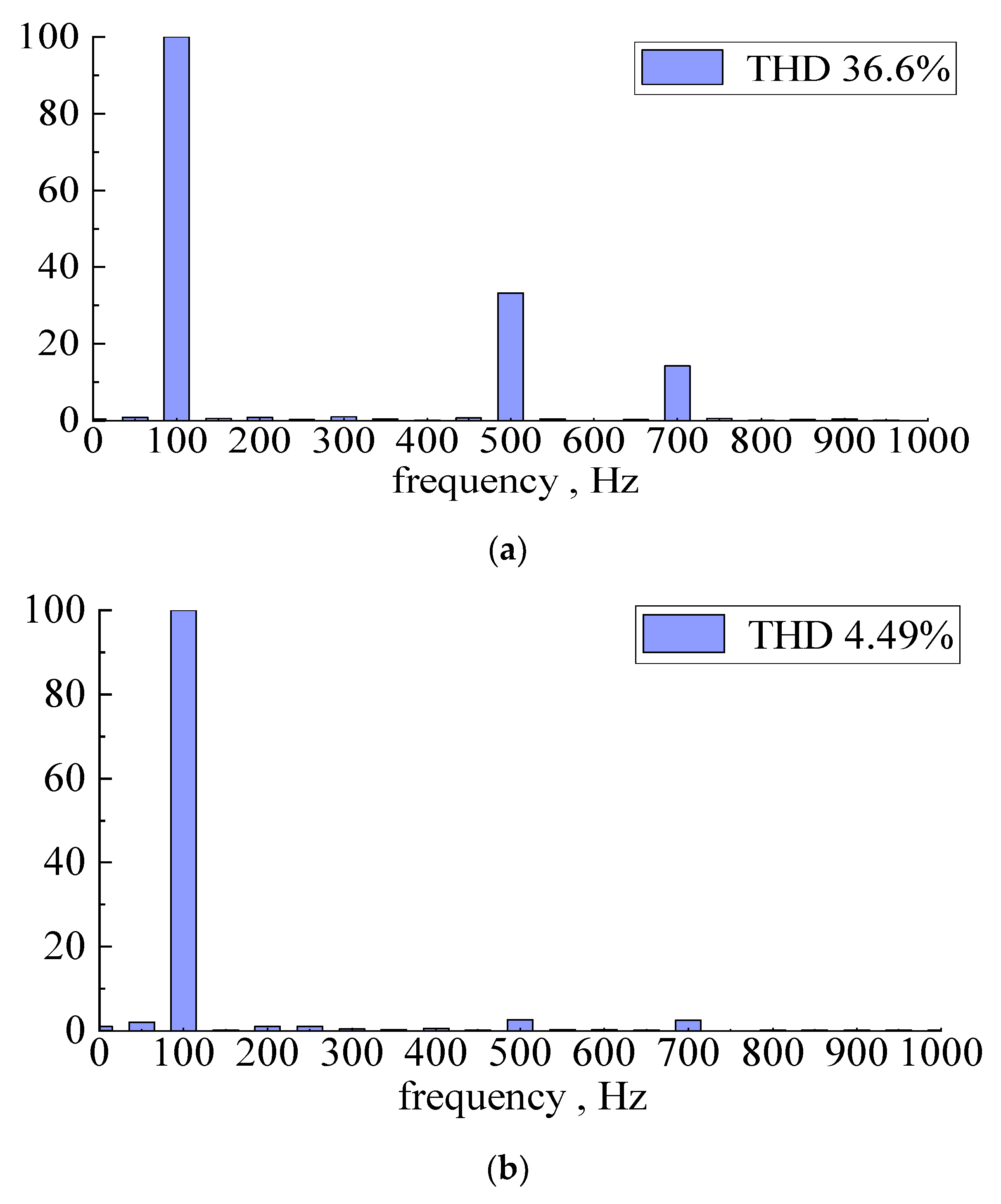
In the simulation, the given speed is 3000 r/min, the fundamental frequency of the motor is 100 Hz, and the phase current fast Fourier transform (FFT) analysis results are presented in Figure 16. After replacing the large vector with a low–harmonic vector, the current harmonic content decreases from 36.6% to 4.49%, as shown in Figure 18. The harmonic suppression effect is remarkable.
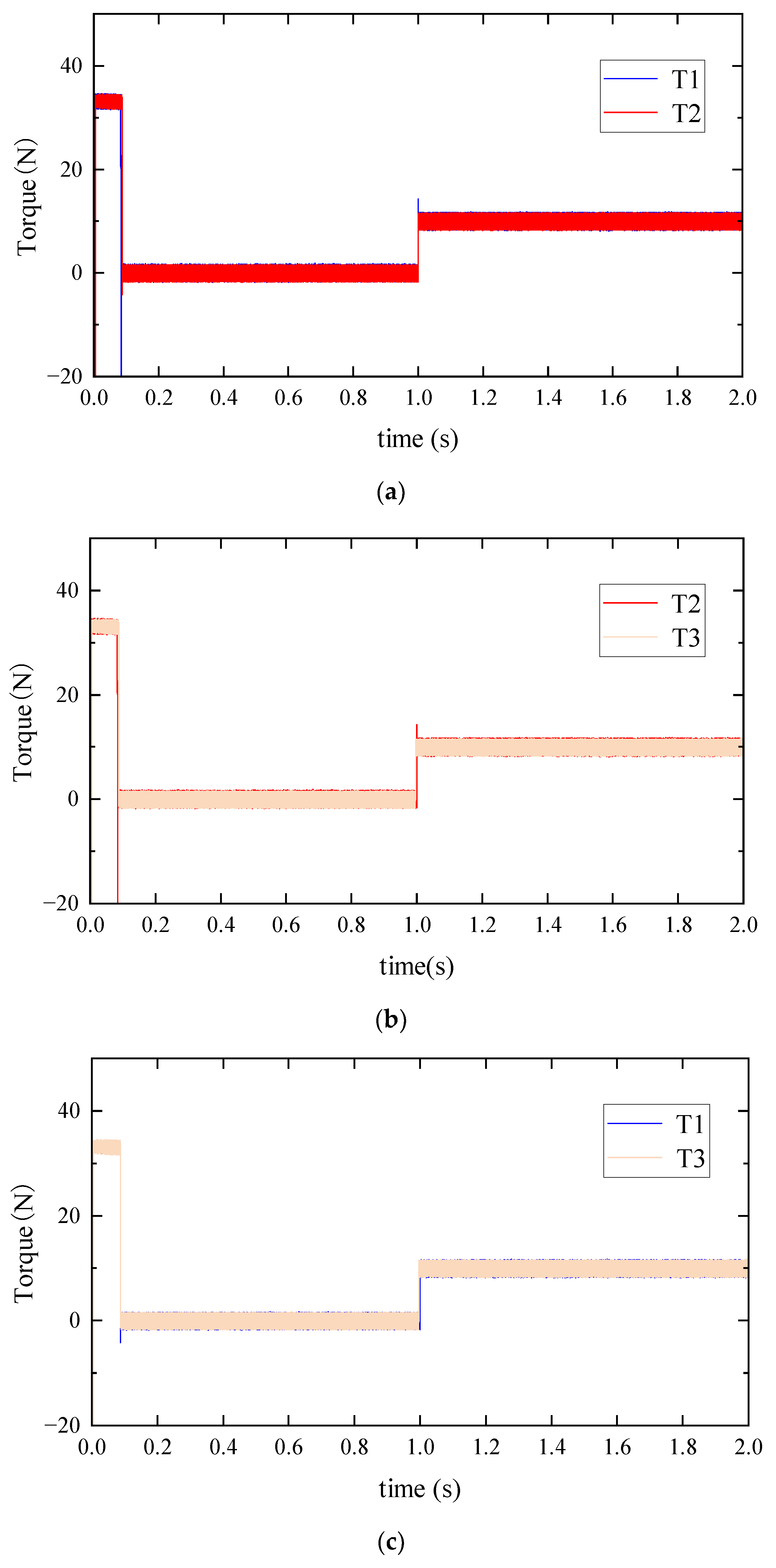
The torque response simulation of the direct torque control of the dual–phase synchronous reluctance motor is shown in Figure 19. Figure 19a is a comparison diagram of torque responses T1 and T2 when the motor is controlled by a large vector and low–harmonic vector. Under the same PI parameters, there is obvious overshoot in the torque response T2 using the low–harmonic vector. When the given torque changes suddenly in 0.1 s and 1 s, the dynamic response performance of the torque decreases. Figure 19b is a comparison diagram of torque response T2 and T3 when the motor is controlled by a low–harmonic vector and improved low–harmonic vector. Improved low–harmonic vectors optimize vector synthesis order. The torque response T3 has no obvious overshoot at 0.1 s and 1 s, and the dynamic response performance of the torque recovers. Figure 19c is a comparison diagram of torque response T1 and T3 when using a large vector and improved low–harmonic vector control motor. When the given torque changes suddenly at 0.1 s and 1 s, the overshoot of torque response T1 and T3 is not obvious, and the dynamic response is the same. This proves that the torque dynamic response performance can be restored to the same as the large vector by optimizing the sequence of low–harmonic vector synthesis.
6. Experimental Verification
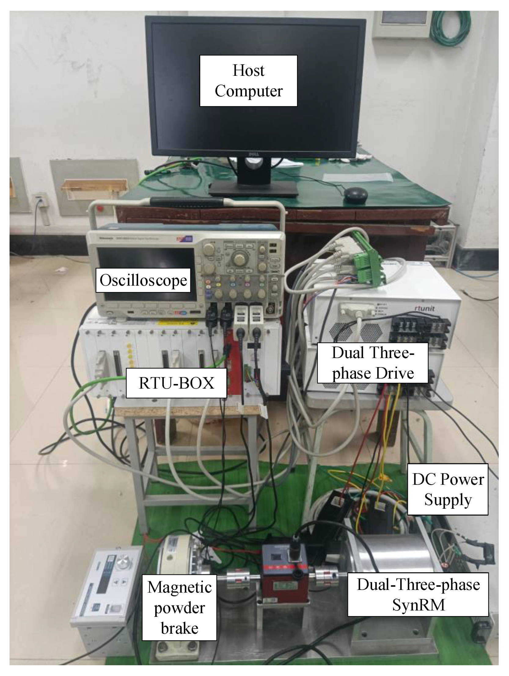
In order to verify the effectiveness of the harmonic suppression strategy, an experimental platform for DTP–SynRM, as shown in Figure 20, was built. The experimental platform consists of a host computer, dual three–phase synchronous reluctance motor, dual three–phase drive, DC power supply, oscilloscope, and RTU–BOX digital controller.
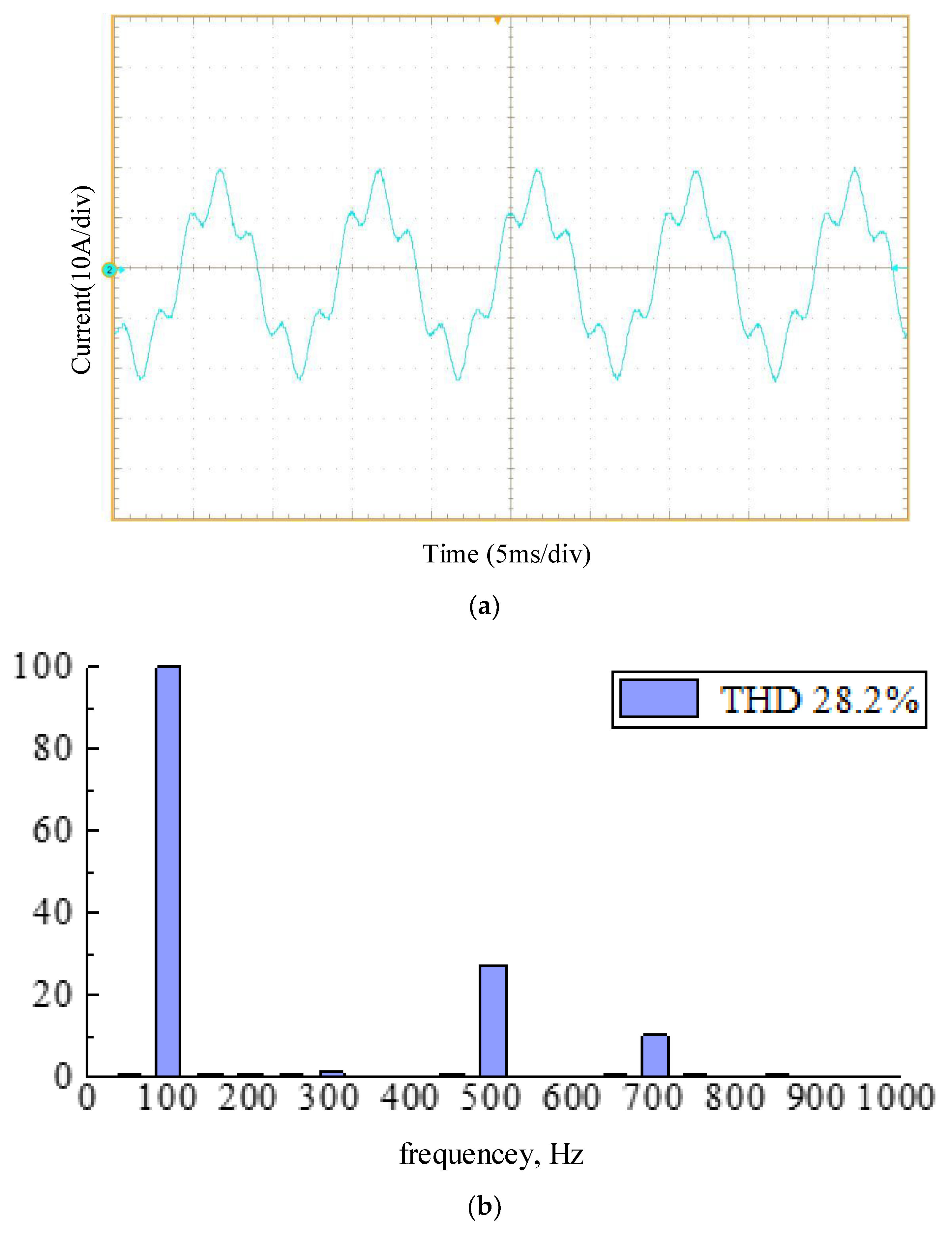
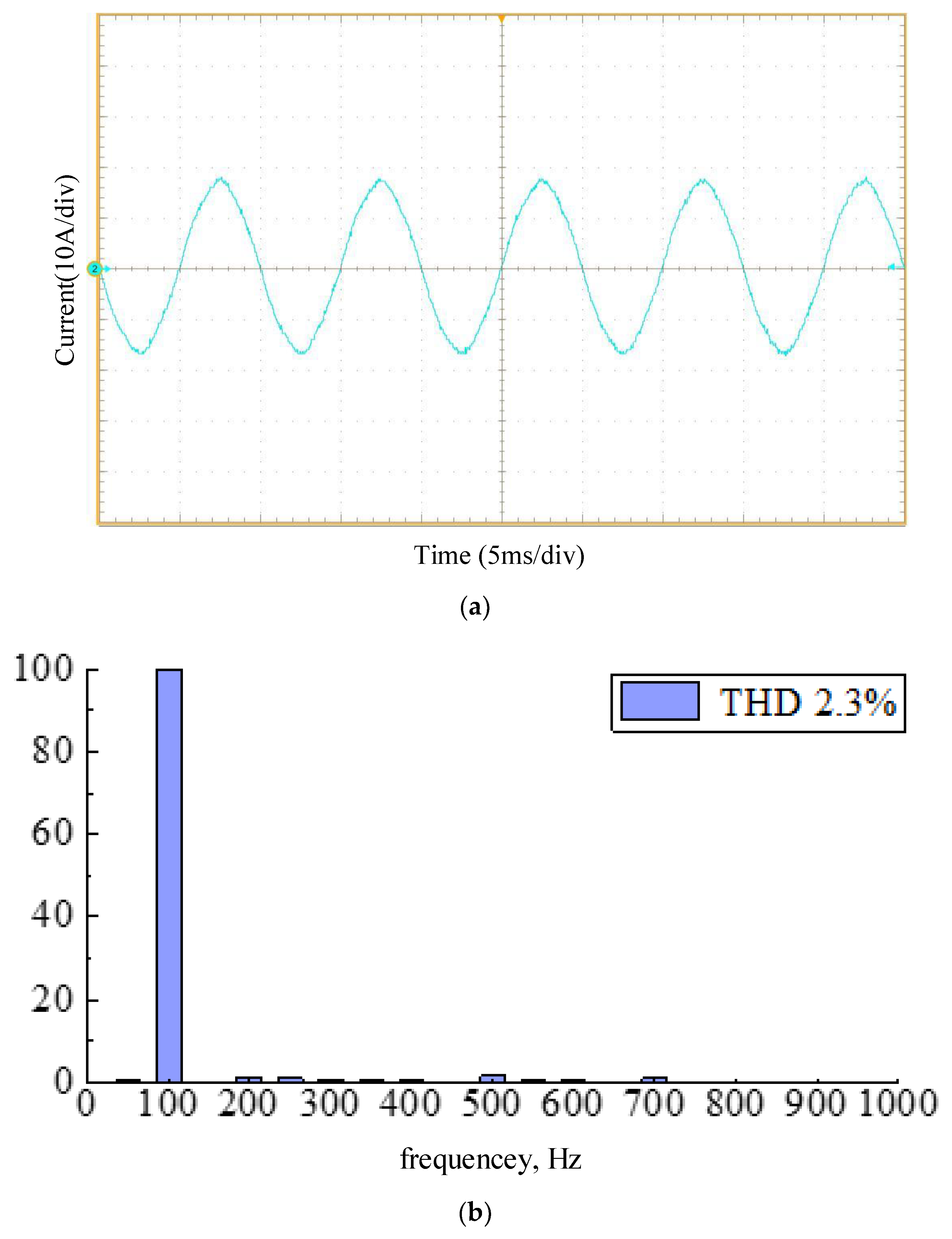
Figure 21 and Figure 22 show the current waveforms of traditional DTC and improved DTC. The traditional DTC applied to the DTP–SynRM has obvious distortion of the current waveform, which indicates that the current contains more harmonics. After FFT analysis, it can be seen that the harmonic content is 28.2%. In the improved direct torque control, the current waveform is more sine wave, and the harmonic content is reduced to 2.6%. The effectiveness of the harmonic suppression strategy can be proved by comparison.
7. Conclusions
DTP–SynRM low–harmonic DTC based on three vector synthesis retains the characteristics of a simple direct torque control structure. It makes full use of three adjacent torque and voltage vectors with the same flux control effect, which has the least dependence on motor parameters. The low–harmonic vector is synthesized to suppress harmonics, and it exhibits the advantages of small calculation amount, easy implementation, and good harmonic suppression effect.
On this basis, the vector sequence in low–harmonic vector synthesis is optimized, and two optimization schemes are proposed: switching frequency reduction type and torque response unchanged type. These two schemes are suitable for high–speed and high–performance control of flywheel batteries, respectively. Finally, the effectiveness of the harmonic suppression strategy is verified by comparative experiments.
Author Contributions
Investigation, Q.W.; Project administration, Y.H.; Software, Y.L., Q.W. and F.Y.; Supervision, Y.H.; Visualization, F.Y.; Writing—original draft, Y.L. All authors have read and agreed to the published version of the manuscript.
Funding
This work was sponsored by National Natural Science Foundation of China (51877101), Key Research and Development Program of Jiangsu Province (BE2021094), Priority Academic Program Development of Jiangsu Higher Education Institutions (PAPD-2018-87).
Institutional Review Board Statement
Not applicable.
Informed Consent Statement
Not applicable.
Data Availability Statement
Not applicable.
Conflicts of Interest
The authors declare no conflict of interest.
References
- Zhang, Z.X. Research on the design of electric vehicle motor drive control system. Times Auto 2022, 14, 127–129. [Google Scholar]
- Zhang, W.Y.; Yang, H.K.; Zhu, R.Q. Analysis of key technologies and technical bottlenecks of flywheel battery for electric vehicles. Proc. CSEE 2018, 38, 5568–5581. [Google Scholar]
- Chen, Y.A.; Gan, S.L.; Zhou, J.H. Energy storage technology of flywheel. Power Technol. 2016, 40, 1718–1721. [Google Scholar]
- Xu, X.; Wang, Y.; Shen, J. Direct Torque Control-Space Vector Modulation Control Strategy of Synchronous Reluctance Motor Based on Maximum Torque Per-Ampere. Trans. China Electrotech. Soc. 2020, 35, 246–254. [Google Scholar]
- Zhou, C.P.; Su, J.Y.; Yang, G.J. Harmonic currents suppression in direct torque control of dual threephase permanent magnet synchronous motor. Electr. Mach. Control 2015, 19, 46–53. [Google Scholar]
- Moghaddam, H.A.; Vahedi, A.; Ebrahimi, S.H. Design Optimization of Transversely Laminated Synchronous Reluctance Machine for Flywheel Energy Storage System Using Response Surface Methodology. IEEE Trans. Ind. Electron. 2017, 64, 9748–9757. [Google Scholar] [CrossRef]
- Chen, X.; Zhou, Y.Z.; Chen, Y.H.; Zhong, T.Y. A new type of SVM–DTC applied to dual–phase PMSM. Power Electron. Technol. 2020, 54, 108–112. [Google Scholar]
- Wang, Y.; Song, W.; Ruan, Z.; Yan, Y. Current Harmonic Suppression Technology for Dual Three–Phase Permanent Magnet Synchronous Motor. In Proceedings of the 2019 IEEE 3rd International Electrical and Energy Conference (CIEEC), Beijing, China, 7–9 September 2019; Volume 72, pp. 678–682. [Google Scholar]
- Zhao, Y.F.; Li, T.A. Space vector PWM control of dual three–phase induction machine using vector space decompostion. IEEE Trans. Ind. Appl. 1995, 31, 1100–1109. [Google Scholar] [CrossRef]
- Yang, J.B.; Yang, G.J.; Li, T.C. Modeling and vector control for dual three–phase PMSM. Electr. Mach. Control 2010, 14, 1–7. [Google Scholar]
- Yu, Y.; Gao, L. 24–Sector space vector decomposition for a dual three–phase PMSM. In Proceedings of the 2014 17th International Conference on Electrical Machines and Systems (ICEMS), Hangzhou, China, 22–25 October 2014; pp. 1601–1606. [Google Scholar] [CrossRef]
- Eldeeb, H.M.; Abdel-Khalik, A.S.; Kullick, J. Pre- and Postfault Current Control of Dual three–phase Reluctance Synchronous Drives. IEEE Trans. Ind. Electron. 2020, 67, 3361–3373. [Google Scholar] [CrossRef]
- Levi, E.; Bojoi, R.; Profumo, F. Multiphase induction motor drives–a technology status review. IET Electr. Power Appl. 2007, 1, 489–516. [Google Scholar] [CrossRef]
- Zheng, L.; Fletcher, J.E.; Williams, B.W. A Novel Direct Torque Control Scheme for a Sensorless Five-Phase Induction Motor Drive. IEEE Trans. Ind. Electron. 2011, 58, 503–513. [Google Scholar] [CrossRef]
- Karttunen, J.; Kallio, S.; Peltoniemi, P.; Silventoinen, P. Current harmonic compensation in dual three–phase PMSMs using a disturbance observer. IEEE Trans. Ind. Electron. 2016, 63, 583–594. [Google Scholar] [CrossRef]
- Wu, L.; Li, J.; Lu, Y.; He, K. Strategy of Synchronized SVPWM for Dual Three–Phase Machines in Full Modulation Range. IEEE Trans. Power Electron. 2022, 37, 3272–3282. [Google Scholar] [CrossRef]
- Shaikh, M.S.; Maurya, R. Performance Investigation on SVPWM Sequences Based on Reduced Common–Mode Voltage in Dual Three–Phase Asymmetrical Machine. IEEE Trans. Energy Convers. 2021, 36, 2884–2893. [Google Scholar]
- Zhang, W.; Chen, B.J.; Zhang, P. Harmonic current suppression technology for dual three–phase permanent magnet synchronous motors. J. Electr. Mach. Control 2015, 19, 23–28. [Google Scholar]
- Mai, Z.Q.; Xiao, F.; Liu, J.L.; Zhang, W.W. Harmonic current suppression strategy of dual three–phase permanent magnet synchronous motor based on quasi proportional resonance cascade PI. J. Electrotech. 2018, 33, 5751–5759. [Google Scholar]
- Ruan, Z.H.; Song, W.X.; Yan, Y. Current Harmonic Suppression for Dual three–phase Permanent Magnet Synchronous Motor Drives. J. IEEE Access 2019, 7, 143888–143898. [Google Scholar] [CrossRef]
- Ye, D.; Li, J.; Qu, R. Variable Switching Sequence PWM Strategy of Dual Three–Phase Machine Drive for High–Frequency Current Harmonic Suppression. IEEE Trans. Power Electron. 2020, 35, 4984–4995. [Google Scholar] [CrossRef]
- Liu, S.; Liu, C.; Huang, Y.; Xiao, Y. Direct Modulation Pattern Control for Dual Three–Phase PMSM Drive System. IEEE Trans. Ind. Electron. 2022, 69, 110–120. [Google Scholar] [CrossRef]
Figure 1.
Motor stator and rotor magnetic core design.

Figure 2.
Motor winding design drawing.

Figure 3.
Spatial distribution of two sets of windings of dual three–phase motor.

Figure 4.
Spatial distribution of 5th harmonic magnetomotive force in two sets of windings.

Figure 5.
Six–phase inverter connected to DTP–SynRM.

Figure 6.
Current phase difference between two sets of windings.

Figure 7.
Dual three–phase motor space voltage vector distribution diagram. (a) Space voltage vector diagram of the fundamental subspace. (b) Space voltage vector diagram of the harmonic subspace.
Figure 7.
Dual three–phase motor space voltage vector distribution diagram. (a) Space voltage vector diagram of the fundamental subspace. (b) Space voltage vector diagram of the harmonic subspace.

Figure 8.
Principle block diagram of DTC of DTP–SynRM.

Figure 9.
Sector division.

Figure 10.
Space voltage vector selection of sector 1.

Figure 11.
Three adjacent large vectors in the fundamental wave subspace mapped onto the harmonic subspace.
Figure 11.
Three adjacent large vectors in the fundamental wave subspace mapped onto the harmonic subspace.

Figure 12.
Selection of space voltage vector in sector 1.

Figure 13.
Switch sequence during M1 synthesis.

Figure 14.
Switching sequence when M1 reduces switching frequency synthesis.

Figure 15.
Switching sequence when M1 is synthesized with constant torque response speed.

Figure 16.
Space voltage vector simulation diagram. (a) Traditional DTC space voltage vector simulation diagram. (b) Low–harmonic DTC space voltage vector simulation diagram.
Figure 16.
Space voltage vector simulation diagram. (a) Traditional DTC space voltage vector simulation diagram. (b) Low–harmonic DTC space voltage vector simulation diagram.

Figure 17.
Dual three–phase current simulation diagram. (a) Traditional DTC current simulation diagram. (b) Low–harmonic DTC current simulation diagram.
Figure 17.
Dual three–phase current simulation diagram. (a) Traditional DTC current simulation diagram. (b) Low–harmonic DTC current simulation diagram.

Figure 18.
Current FFT analysis simulation diagram. (a) Traditional DTC current FFT analysis simulation diagram. (b) Low–harmonic DTC current FFT analysis simulation diagram.
Figure 18.
Current FFT analysis simulation diagram. (a) Traditional DTC current FFT analysis simulation diagram. (b) Low–harmonic DTC current FFT analysis simulation diagram.

Figure 19.
Torque response simulation diagram. (a) Comparison of large vector torque response and low–harmonic vector torque response. (b) Comparison of low–harmonic vector torque response and improved low–harmonic vector torque response. (c) Comparison of large vector torque response and improved low harmonic vector torque response.

Figure 20.
DTP–SynRM experimental platform.

Figure 21.
Traditional DTC current experimental waveform. (a) Traditional DTC current experimental diagram. (b) Traditional DTC current FFT analysis diagram.
Figure 21.
Traditional DTC current experimental waveform. (a) Traditional DTC current experimental diagram. (b) Traditional DTC current FFT analysis diagram.

Figure 22.
Improved DTC current experimental waveform. (a) Improved DTC current experimental diagram. (b) Improved DTC current FFT analysis diagram.
Figure 22.
Improved DTC current experimental waveform. (a) Improved DTC current experimental diagram. (b) Improved DTC current FFT analysis diagram.


Table 1.
Traditional DTC switch table.
| n | S1 | S2 | S3 | S4 | S5 | S6 | |
|---|---|---|---|---|---|---|---|
| DF = 1 | DT = 1 | V27 | V26 | V18 | V22 | V54 | V52 |
| DT = 0 | V37 | V45 | V41 | V9 | V11 | V27 | |
| DF = 0 | DT = 1 | V26 | V18 | V22 | V54 | V52 | V36 |
| DT = 0 | V36 | V37 | V45 | V41 | V9 | V11 | |
| n | S7 | S8 | S9 | S10 | S11 | S12 | |
| DF = 1 | DT = 1 | V36 | V37 | V45 | V41 | V9 | V11 |
| DT = 0 | V26 | V18 | V22 | V54 | V52 | V36 | |
| DF = 0 | DT = 1 | V37 | V45 | V41 | V9 | V11 | V27 |
| DT = 0 | V27 | V26 | V18 | V22 | V54 | V52 |
Table 2.
Low–harmonic vector synthesis table.
| Large Vector | Three Vectors Used in Synthesis | Low–Harmonic Vector | ||
|---|---|---|---|---|
| V9 | V41 | V9 | V11 | M1 |
| V11 | V9 | V11 | V27 | M2 |
| V27 | V11 | V27 | V26 | M3 |
| V26 | V27 | V26 | V18 | M4 |
| V18 | V26 | V18 | V22 | M5 |
| V22 | V18 | V22 | V54 | M6 |
| V54 | V22 | V54 | V52 | M7 |
| V52 | V54 | V52 | V36 | M8 |
| V36 | V52 | V36 | V37 | M9 |
| V67 | V36 | V37 | V45 | M10 |
| V45 | V37 | V45 | V41 | M11 |
| V41 | V45 | V41 | V9 | M12 |
Table 3.
Harmonic suppression switch table.
| n | S1 | S2 | S3 | S4 | S5 | S6 | |
|---|---|---|---|---|---|---|---|
| DF = 1 | DT = 1 | M2 | M3 | M4 | M5 | M6 | M7 |
| DT = 0 | M11 | M12 | M1 | M2 | M3 | M4 | |
| DF = 0 | DT = 1 | M5 | M6 | M7 | M8 | M9 | M10 |
| DT = 0 | M8 | M9 | M10 | M11 | M12 | M1 | |
| n | S7 | S8 | S9 | S10 | S11 | S12 | |
| DF = 1 | DT = 1 | M8 | M9 | M10 | M11 | M12 | M1 |
| DT = 0 | M5 | M6 | M7 | M8 | M9 | M10 | |
| DF = 0 | DT = 1 | M11 | M12 | M1 | M2 | M3 | M4 |
| DT = 0 | M2 | M3 | M4 | M5 | M6 | M7 |
Table 4.
Motor parameter table.
| Motor Parameters | Numerical Value |
|---|---|
| Inverter DC link voltage | 300 V |
| Fundamental frequency | 100 Hz |
| Number of pole pairs | 2 |
| d–axis inductance | 0.0276 mH |
| q–axis inductance | 0.014 mH |
| Stator resistance (per phase) | 0.2 Ω |
| Moment of inertia | 0.0486 kg·m2 |
| Base speed | 3000 rpm |
Publisher’s Note: MDPI stays neutral with regard to jurisdictional claims in published maps and institutional affiliations. |
© 2022 by the authors. Licensee MDPI, Basel, Switzerland. This article is an open access article distributed under the terms and conditions of the Creative Commons Attribution (CC BY) license (https://creativecommons.org/licenses/by/4.0/).
Share and Cite
MDPI and ACS Style
Huang, Y.; Liu, Y.; Wang, Q.; Yang, F. Low–Harmonic Control Strategy of a Dual Three–Phase Synchronous Reluctance Motor Based on Three–Vector Synthesis. Energies 2022, 15, 6350. https://0-doi-org.brum.beds.ac.uk/10.3390/en15176350
AMA Style
Huang Y, Liu Y, Wang Q, Yang F. Low–Harmonic Control Strategy of a Dual Three–Phase Synchronous Reluctance Motor Based on Three–Vector Synthesis. Energies. 2022; 15(17):6350. https://0-doi-org.brum.beds.ac.uk/10.3390/en15176350
Chicago/Turabian StyleHuang, Yonghong, Yihang Liu, Qicuan Wang, and Fan Yang. 2022. "Low–Harmonic Control Strategy of a Dual Three–Phase Synchronous Reluctance Motor Based on Three–Vector Synthesis" Energies 15, no. 17: 6350. https://0-doi-org.brum.beds.ac.uk/10.3390/en15176350
Note that from the first issue of 2016, this journal uses article numbers instead of page numbers. See further details here.