
Design and Optimization Method with Independent Radial and Axial Capacity for 3-DOF Magnetic Bearings in Flywheel
1
School of Electrical and Information Engineering, Changzhou Institute of Technology, Changzhou 212031, China
2
School of Mechanical Engineering and Rail Transit, Changzhou University, Changzhou 213164, China
*
Author to whom correspondence should be addressed.
Energies 2023, 16(1), 483; https://0-doi-org.brum.beds.ac.uk/10.3390/en16010483
Submission received: 11 November 2022
/
Revised: 25 December 2022
/
Accepted: 29 December 2022
/
Published: 1 January 2023
(This article belongs to the Special Issue Design and Control of Flywheel Energy Storage Systems)
Abstract
:The six-pole radial–axial hybrid magnetic bearing (RAHMB) has the advantages of small space and low power consumption, making it suitable for flywheel batteries. The bearing capacity and the volume are the main specifications of magnetic bearings that should be considered comprehensively. In this work, the six-pole RAHMB was used in a horizontal flywheel battery. As the axial bearing capacity is relatively smaller than the radial bearing capacity, a design method with independent radial and axial bearing capacity is proposed, and the parameters are optimized to minimize the volume. The mathematical model of six-pole RAHMB was derived from the equivalent magnetic circuit method. The relationships between bearing capacity, biased flux density, saturation flux density and the section area of magnetic poles were analyzed. The basic principle of the design method with independent radial and axial bearing capacity is to determine which five of the variables are preferred. According to the design method, one radial or axial biased flux density should be optimized to minimize the volume, and the genetic algorithm (GA) was adopted to search for the optimal value. The structural parameters were designed based on the optimized value of biased flux density. The total volume of the six-pole RAHMB was reduced by 24%. A 3D finite element (FE) model was built. The analysis results and experimental results show that the proposed design and the optimization method are feasible and valid.
1. Introduction
Given their qualities of no friction, no wear, no lubrication, high speed, high precision and long service life, magnetic bearings are increasingly widely used in various types of rotating machinery, such as air blowers, compressors, turbine generators, turbomolecular pumps, flywheel batteries, control moment gyros, etc. [1,2,3,4,5,6].
The magnetically levitated flywheel has the advantages of high efficiency, high power density, high energy storage density, fast charging and discharging, long service life and no pollution [7]. The structure of one axial magnetic bearing and two radial magnetic bearings is commonly used in flywheel systems [8]. To reduce the volume, weight and power loss, permanent biased magnetic bearings and combined radial–axial magnetic bearings (CRAMB) have received more and more attention [9]. To improve the performance and better meet engineering requirements of the magnetic suspension compressor, the CRAMB is optimized by the method of multi-objective optimization in which the volume, axial length, suspension force and eddy current loss are all considered [2]. A novel CRAMB in a large-scale magnetically suspended control moment gyro (MSCMG) was designed to reduce the weight, volume and power consumption of the MSCMG [10]. The electrical machine and magnetic bearing were both taken into account in the objective function of the genetic algorithm to optimize a high-speed electrical machine [11]. A heteropolar radial hybrid magnetic bearing (HMB) in the flywheel energy storage system was optimized by considering second air-gap length, permanent magnet (PM) height, width and other key parameters [12]. A 300,000 r/min magnetically levitated reaction wheel was presented, which consists of a slotless, bearingless motor and ironless radial and axial magnetic bearing [13]. A multiphysics global design method for a magnetic bearing supporting electrical machine is proposed in [1]. A design method of a six-pole HMB considering the variable stiffness caused by rotor eccentricity is proposed in [14]. The force density of the three-pole magnetic bearing was improved up to 15.5% by the design method based on the exact control current and optimal biased field calculation [15]. The comprehensive sensitivity was analyzed and the cross-factor variance analysis was considered when optimizing the three-degree-of-freedom magnetic bearing by the Kriging model and the non-dominated Sorting Genetic Algorithm (GA) [16]. An analytical model was built to design the cycloid magnetic gear, and the parameters were optimized by establishing objective function and constraint function based on the analytical model [17].
The radial–axial hybrid magnetic bearing (RAHMB) combines radial and axial magnetic bearing into one component and the biased flux is generated by PM, so it has the advantages of small space, small axial length, small diameter and low power consumption [18]. In particular, the six-pole RAHMB can be driven by a three-phase power converter, which has been widely used in motor driving.
Most of the design and optimization methods mentioned above mainly focus on the dimension of structural parameters for better performance in weight, volume, suspension force, loss and other factors. However, when designing the initial parameters, the coupling between radial bearing capacity and axial bearing capacity and how to appropriately deal with the coupling have not been reported. In this article, a horizontal flywheel is designed with a six-pole RAHMB. As the radial bearing capacity is much larger than the axial bearing capacity, a design and an optimization method with independent radial and axial bearing capacities for a six-pole RAHMB are proposed. Firstly, the mathematical model of the six-pole RAHMB is derived based on the equivalent magnetic circuit method. Then, the relationships between maximum suspension force, biased flux density, saturation flux density and section area of magnetic poles are analyzed. We found that there are eight variables which are constrained by three functions, namely the radial bearing capacity, the axial bearing capacity and the relationship between radial and axial biased flux. As only five variables can be set freely, the radial and axial bearing capacities may be coupled with each other if the radial and axial biased and saturation flux densities are set according to the material properties. So, the radial and axial bearing capacities should be set first to ensure that they are independent from each other to satisfy the requirement of horizontal flywheel. Among the remaining four variables of flux density, three of them can be set freely, and the principle of setting which three variables preferentially is proposed. During the design, one of the radial or axial biased flux densities should be set last, and the value should be optimized to minimize the volume and maximize the suspension force. So, the objective function is derived and the GA is applied to optimize the last variable. Finally, we analyzed the performance of the optimized results by finite element (FE) simulation and experiments.
2. Mathematical Model of the Six-Pole RAHMB
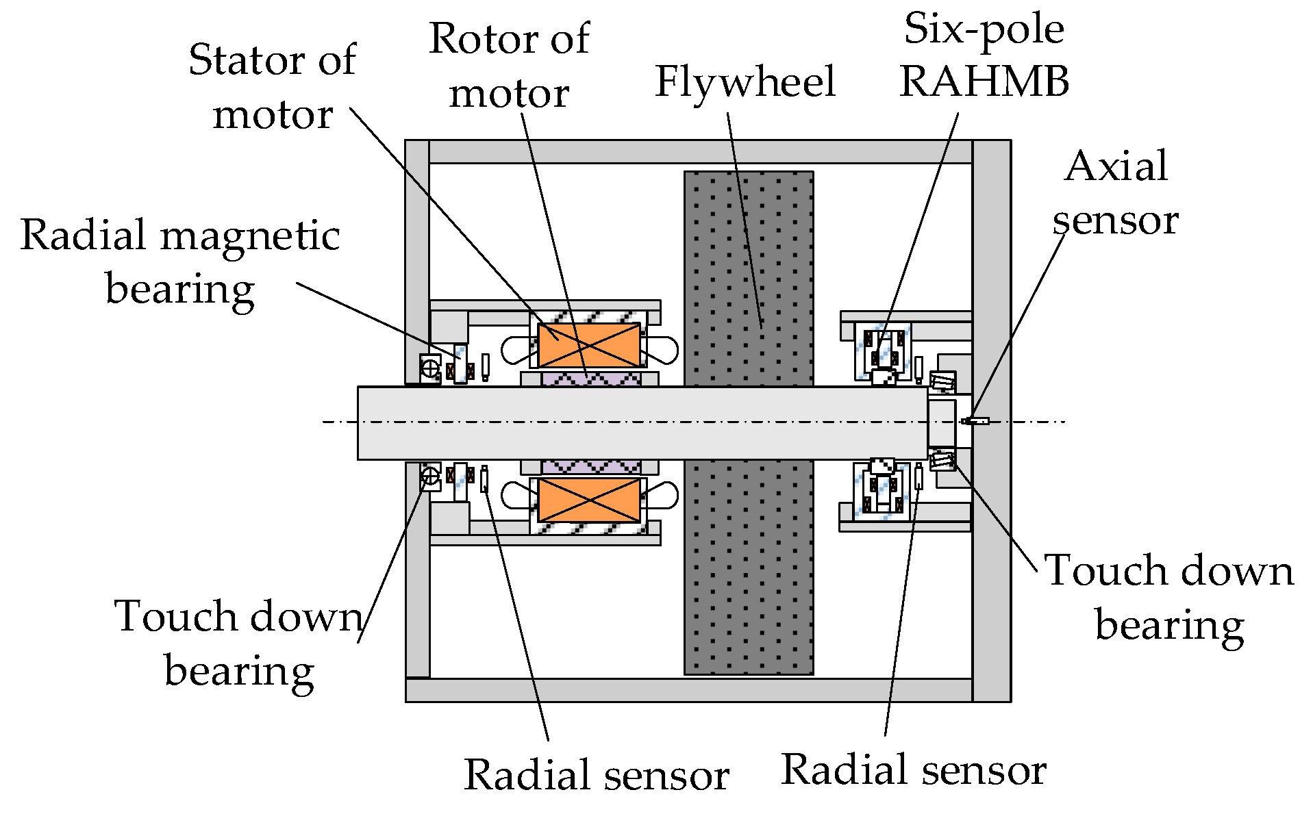
The main structure diagram of a flywheel battery is shown in Figure 1. The six-pole RAHMB is placed on the left end of the flywheel battery. The total weight of the flywheel rotor and rotating shaft is 15 kg, which is borne by the two radial magnetic bearings. So, the radial bearing capacity was set to 200 N considering a certain margin. The axial part of the six-pole RAHMB is used to control the axial eccentricity of the rotor, which needs a smaller bearing capacity; thus, the axial bearing capacity was set to 100 N. The following optimization of six-pole RAHMB is based on the demand of the axial and radial bearing capacities above.
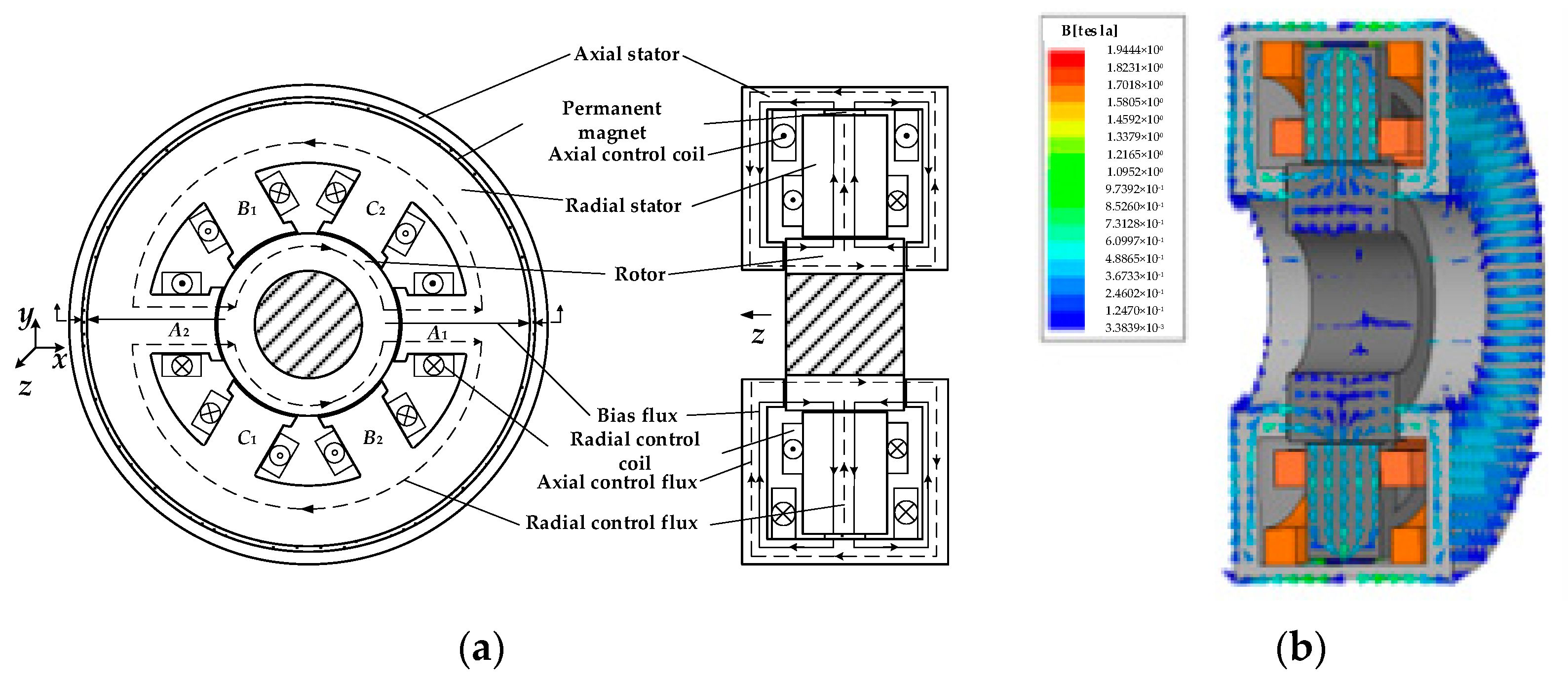
The six-pole RAHMB consists of axial stator, radial stator, PM, rotor, radial control coils and axial control coils, as shown in Figure 2a. The PM is annular and magnetized along the radial direction. The biased flux generated by PM flows out from the outer torus and then flows into the axial stator. The axial stator is composed of one cylinder, two discs and two annular axial magnetic poles. The biased flux flows from axial magnetic poles into the axial air gap between the rotor and axial stator, flows through the radial air gap and radial stator, and finally flows back to the inner torus of PM. The vector diagram of flux path in the six-pole RAHMB is shown in Figure 2b. The radial control flux generated by radial control coils flows in the loop of radial stator, radial air gap and rotor. The axial control flux generated by axial control coils flows in the loop of axial stator, axial air gap and rotor. The radial/axial control flux and the biased flux are superimposed in one radial/axial air gap and are offset in the opposite radial/axial air gap; thus, the suspension forces along the radial/axial magnetic poles are generated.
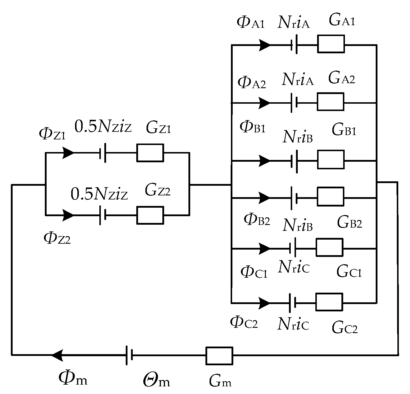
Assuming that the magnetic fields in the magnetic poles are uniform and neglecting the flux leakage and reluctance of iron, the equivalent magnetic circuit of the six-pole RAHMB can be obtained, as shown in Figure 3.
In Figure 3, the Θm is the magnetomotive force of PM, Φm is the flux of PM, NZ represents the total turns of left and right axial control coils and iZ is the axial control current. ΦZ1 and ΦZ2 are the fluxes of left and right axial air gaps, respectively. ΦA1, ΦA2, ΦB1, ΦB2, ΦC1 and ΦC2 are the fluxes in the six radial air gaps. iA, iB and iC are the three phase control currents. Gm is the permeance of the PM. GZ1 and GZ2 are the permeances of left and right axial air gaps, respectively. GA1, GA2, GB1, GB2, GC1 and GC2 are the permeances of six radial air gaps. The permeances of the air gaps and PM can be given by
where μ0 is the vacuum permeability; Sm is the sectional area of PM; lm is the magnetization length of PM; SZ and Sr are the sectional areas of axial and radial magnetic poles, respectively; δZ and δr are the lengths of axial and radial air gaps, respectively; z is the axial displacement of rotor; and x and y are the displacement of the rotor along the two radial coordinate axes, respectively.
The fluxes in the axial air gaps can be derived as follows:
where Φrcoup = NriA(GA1 − GA2) + NriB(GB1 − GB2) + NriC(GC1 − GC2), Grsum = GA1 + GA2 + GB1 + GB2 + GC1 + GC2 and GZsum = GZ1 + GZ2.
The fluxes in the radial air gaps can be derived as follows:
where ΦZcoup = 0.5NZiZ(GZ1 − GZ2).
The magnetic force of radial and axial magnetic poles can be calculated by
3. Design Method with Independent Radial and Axial Bearing Capacity
3.1. Relationship between Radial and Axial Bearing Capacity and Flux Density
The bearing capacity analysis is based on the assumptions that the rotor is in the center position, the permeances of each radial air gap are equal and the permeances of each axial air gap are equal, which means GA1 = GA2 = GB1 = GB2 = GC1 = GC2 = Gr0 and GZ1 = GZ2 = GZ0.
When the control current is zero, the flux densities of air gaps are the biased flux density, and the fluxes of axial air gaps can be expressed by
where BZ0 is the axial biased flux density in axial air gaps.
When the axial control current is maximized, namely iZmax, the flux density of the Z1 axial air gap is BZS, which is set as the axial saturated flux density; the flux of axial air gap Z1 can be derived as follows:
The first term of Equation (6) is equal to the biased flux in Equation (5). The relationship between the maximum axial control current iZmax and axial biased and saturated flux density can be derived as follows:
Then, the flux in axial air gap Z2 can be calculated as follows:
So, according to Equations (6) and (8), the relationship between axial bearing capacity and axial biased and saturated flux density can be derived as follows:
The analysis of radial bearing capacity is similar to axial bearing capacity. Taking an A-phase magnetic pole as an example, the radial biased fluxes without control current can be expressed by
where Br0 is the radial biased flux density in radial air gaps.
When the control current of an A-phase magnetic pole is maximized, namely irmax, the flux in air gaps A1 and A2 can be calculated by
where BrS is the radial saturated flux density.
As the radial control coils of the six-pole RAHMB are driven by a three-phase converter, the control current of B and C phases would be −0.5irmax to generate the maximum radial suspension force. So, the flux in B- and C-phase air gaps can be calculated as follows:
Projecting the forces of six radial magnetic poles onto the x-axis, the maximum suspension force in the x direction can be derived as follows:
As the biased flux is generated by PM, the sum of biased flux in axial air gaps is equal to the sum of biased flux in the radial air gap, which can be expressed by
3.2. Design Principle
In Equations (9), (13) and (14), there are eight variables, namely Frmax, FZmax, Br0, BrS, BZ0, BZS, Sr and SZ; five of them can be determined freely. The magnetic bearing must satisfy the demand of the radial and axial bearing capacity, which means the Frmax and FZmax must be set first. Finally, the sectional areas of axial and radial magnetic poles Sr and SZ would be calculated. So, among the remaining four variables of flux density, Br0, BrS, BZ0 and BZS, three of them can be selected freely and the last one must be calculated. The principle of which three flux density variables to be determined first is as follows: if 2Frmax > FZmax, the radial saturation flux density BrS should be selected according to the saturated flux density of rotor and stator material. The radial biased flux density is half of the radial saturation flux density, i.e., Br0 = 0.5BrS. The axial biased flux density BZ0 should be optimized to obtain a smaller volume and larger bearing capacity; if 2Frmax < FZmax, the axial saturated flux BZS should be selected first, the axial biased flux density is half the axial saturated flux density, BZ0 = 0.5BZS and the radial biased flux density should be optimized.
4. The Biased Flux Density Optimization
As the radial bearing capacity is 200 N, the axial max bearing capacity is 100 N. So, the radial saturated and biased flux density should be selected first. Considering the nonlinearity of stator material, the saturated flux density is set as 0.8 T. The radial saturated flux density BrS should be 0.8 T and the radial biased flux density Br0 should be 0.4 T. According to Equation (13), the area of radial magnetic poles can be calculated as
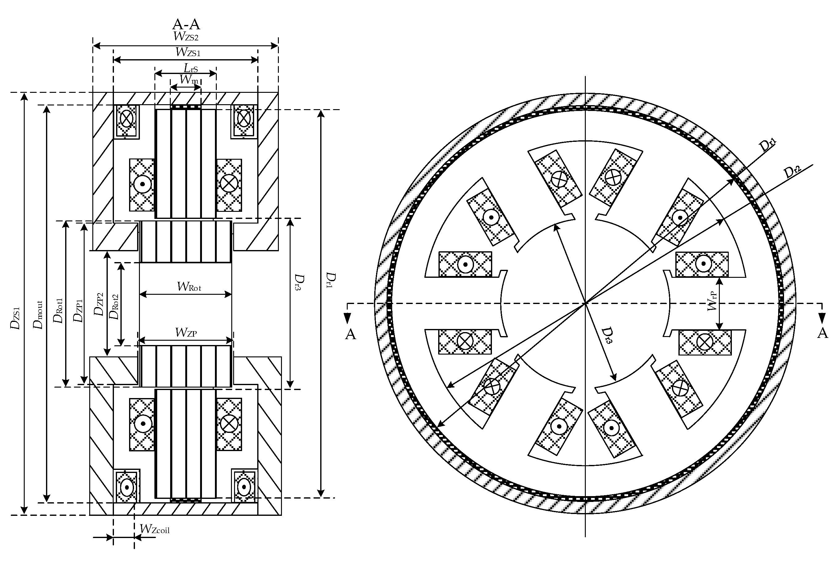
The structural parameters are shown in Figure 4, and the parameters of the radial stator and rotor can be designed based on Sr, as shown in Table 1.
4.1. Objective Function
The optimization principle of axial biased flux density is that the larger the BZ0 is, the smaller the area of axial magnetic poles is and the smaller the volume is; however, when the rotor is off-center, the larger the force generated by the eccentric of rotor is and the smaller the suspension force is.
According to the above principle, the first objective function is the relationship between volume and axial biased flux density. As the parameters of radial stator have been designed, the volume is mainly dependent on the axial stator, which is designed based on the area of axial magnetic poles. According to Equation (14), the area of axial magnetic poles can be deduced:
The outer diameter of axial magnetic poles DZP1 should be smaller than the outer diameter of rotor DRot1, so the outer diameter of axial magnetic poles can be calculated by
According to DZP1 and SZ, the inner diameter of axial magnetic poles DZP2 can be calculated by
The width of the axial stator (WZS2) is the sum of the width of the rotor (WRot), axial air gaps (δZ), the axial width of control coils (Wcoil) and the thickness of the axial stator disk (WZSdisc). As the thickness of the axial stator disk should be at least larger than the width of the axial magnetic poles to avoid saturation in the axial stator disk, the width of the axial stator (WZS2) can be expressed by
To avoid saturation, the outer diameter of the axial stator (DZS1) can be calculated as
The first objective function is the total volume of the six-pole RAHMB, which can be calculated by
The second objective function is the maximum magnetic force when the rotor is at the maximum eccentricity (−0.5δZ) in the axial direction. In this condition, the axial control current is maximized (NZiZmax) and the flux in axial air gaps can be calculated as follows:
Substituting Equations (7) and (16) into (22), the second objective function of the axial bearing capacity when the rotor is at maximum eccentricity can be calculated as follows:
4.2. Constraints
The axial biased flux density should be larger than 0 and smaller than the saturated flux density, which is set as 0.8 T. The constraint can be expressed by
4.3. Optimization of Axial Biased Flux Density
The GA is adopted to optimize the axial biased flux density. The genetic algorithm mainly consists of the following steps: (1) the population should be initialized; (2) the fitness of individuals is calculated; (3) the high-fitness individuals are selected from the current population by the roulette method; (4) new cross individuals are generated by cross operations; (5) new individuals are generated by mutation operations; (6) judge whether to terminate the algorithm by analyzing whether the optimization criteria are met.
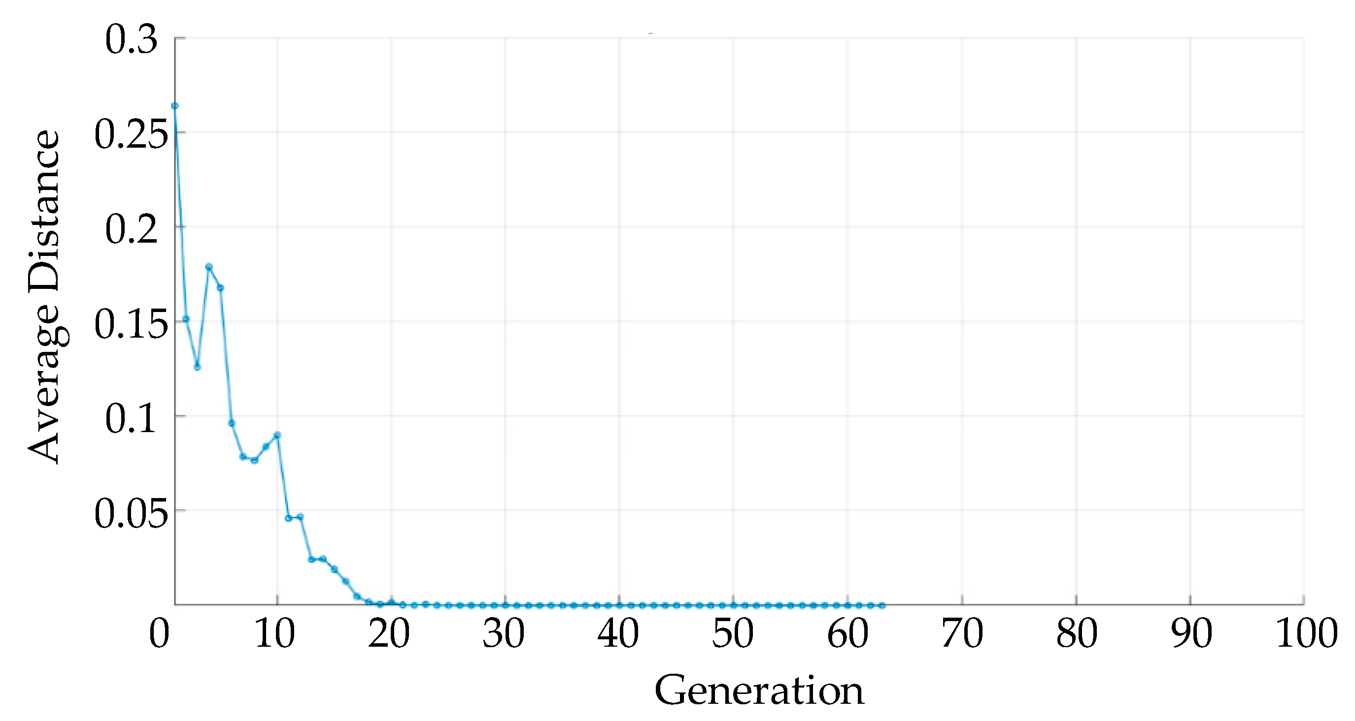
The two objective functions are normalized, and the weighting coefficients of both functions are 0.5. The GA processes were realized in MATLAB, and the optimization results are shown in Figure 5.
The biased flux density reaches the optimal value after 20 generations, and the optimal value is 0.377 T. Then, the parameters of axial stator are designed, as shown in Table 2. In order to compare with the design method proposed in this paper, a set of axial stator parameters were designed based on the traditional design method without independent radial and axial bearing capacity, as shown in Table 2.
The volume of the six-pole RAHMB with and without independent radial and axial bearing capacity is 886,738 mm3 and 1,176,664 mm3, respectively, which means the volume is reduced by 24%.
5. FE Simulation and Analysis
5.1. Biased Flux Density Analysis
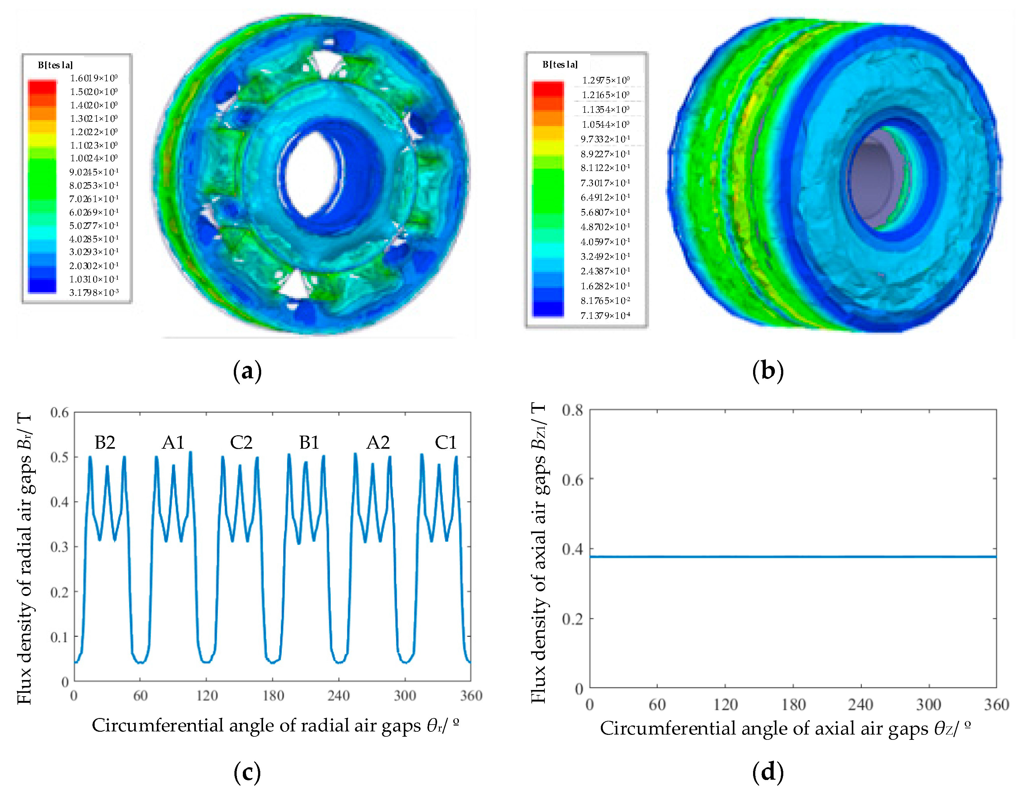
The 3D FE analysis model based on the optimized parameters was built in Maxwell Ansoft. The radial and axial biased flux densities were analyzed and the results are shown in Figure 6. It can be seen that the flux in six radial air gaps and two axial air gaps is uniformly distributed. The average value of radial biased flux density is 0.4 T and the average value of axial biased flux density is 0.377 T, consistent with the design values.
5.2. Radial Maximum Suspension Force Analysis
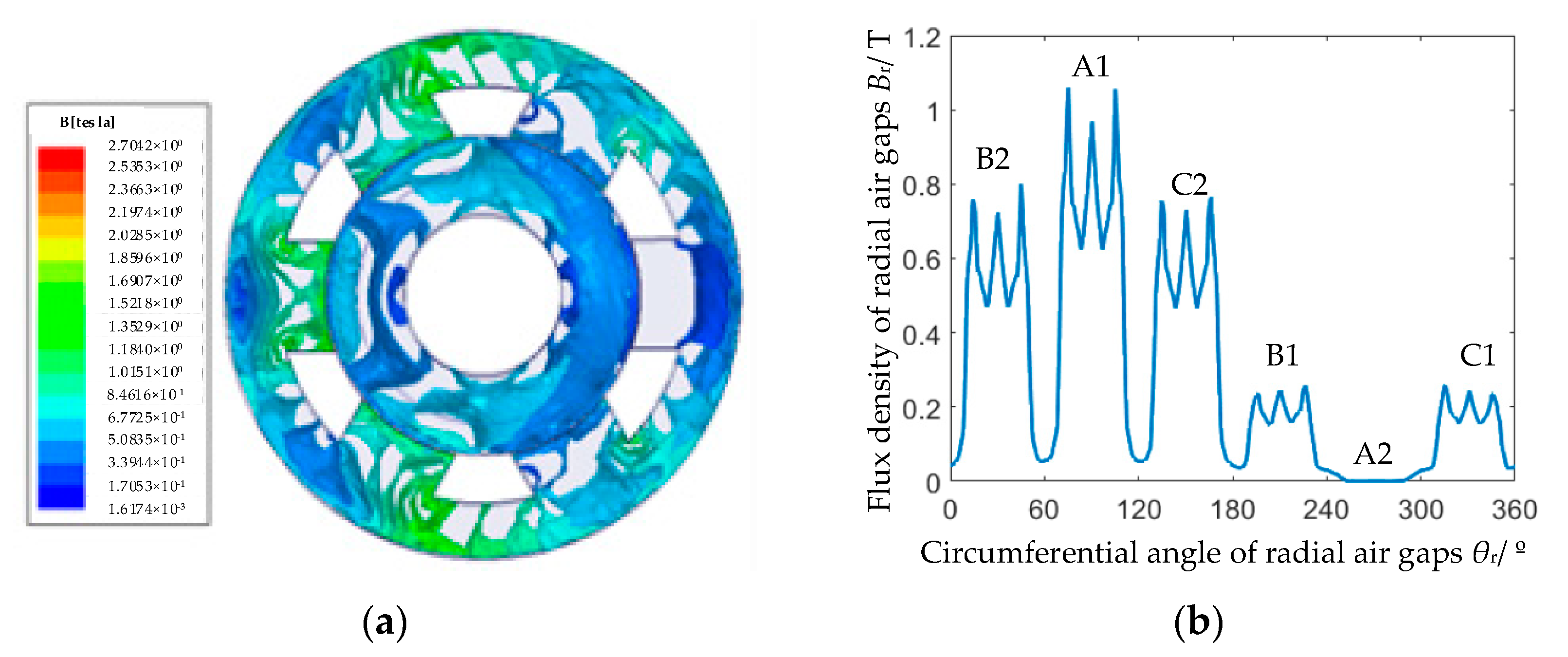
As the maximum current in radial control coils is 160 A, the control current of the A-phase coil is set as 160 A, and that of B and C phases is set as −80 A to validate the performance of the radial bearing capacity. As the axial flux density has little change, only the analysis results of radial flux densities are shown in Figure 7. It can be seen that the average value of flux density in the A1 air gap is 0.79 T, that in the A2 air gap is 0 T, that in the B2 and C2 air gaps is 0.59 T and that in the B1 and C1 air gaps is 0.2 T. The maximum radial bearing force is 210 N, which meets the requirement for the radial bearing capacity.
5.3. Axial Maximum Suspension Force Analysis
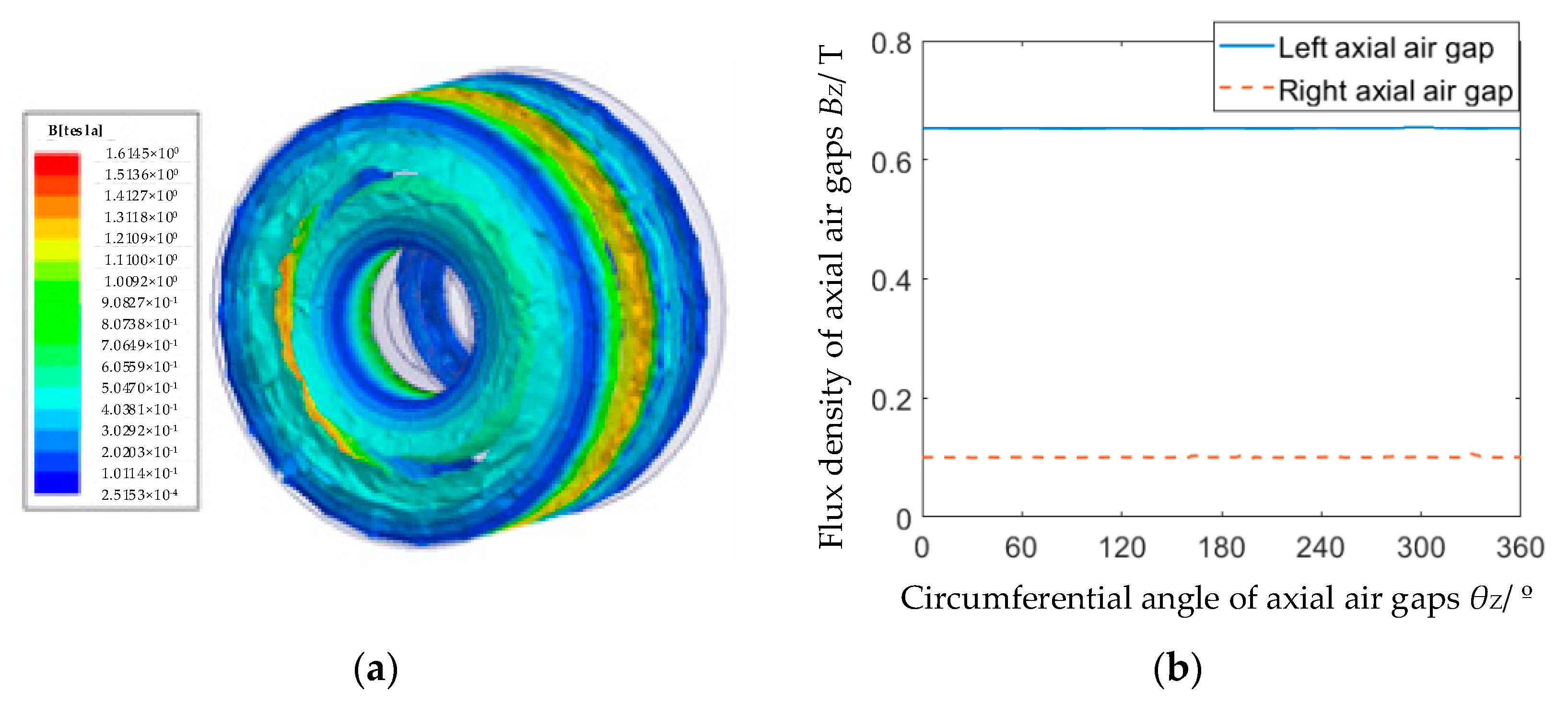
The total control currents in axial coils are set as 80 A to validate the performance of the axial bearing capacity. The flux density results with the maximum axial control current are shown in Figure 8. It can be seen that the flux density of the left axial air gap is 0.66 T, which is similar to the designed value of axial saturation flux density, and the flux density of the right axial air gap is 0.1 T. The maximum axial suspension force is 115 N, which meets the requirement for axial bearing capacity.
6. Experimental Validation
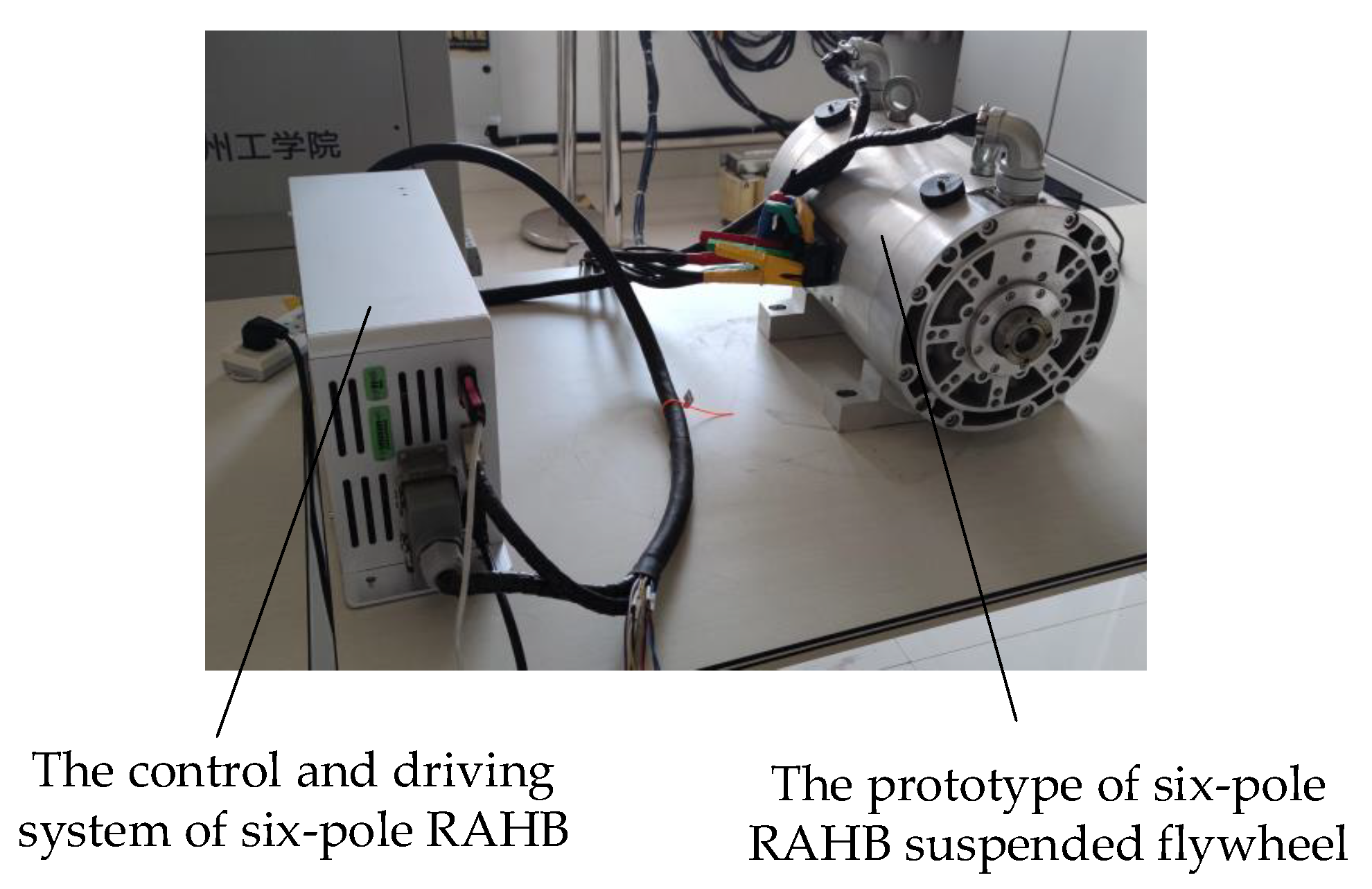
The flywheel system prototype was manufactured based on the designed and optimized parameters, as shown in Figure 9. The axial and radial bearing capacities were tested to validate the correctness of the design and optimization method. As the calculation and simulation results are based on the non-eccentric rotor, the rotor should be fixed in the center of radial and axial displacement when testing the radial and axial bearing capacity. When the turns of radial coils amount to 40, inject 4 A current into A-phase coils and −2 A current into B-phase and C-phase coils to generate the radial bearing capacity. The radial bearing capacity was tested by a pressure sensor and the value was 208 N. When the turns of axial coil amount to 40, inject 2 A current into axial coils. The measurement value of the axial bearing capacity was 110 N. The comparison of experimental results, FE analysis results and calculation results is shown in Table 3, illustrating that the results are consistent with each other.
7. Conclusions
In this work, a mathematical model of a six-pole RAHMB was built by the equivalent magnetic circuit method. The relationships between the bearing capacity in axial and radial directions, saturation flux density in axial and radial air gaps, biased flux density in axial and radial air gaps and the section area of axial and radial magnetic poles were analyzed. We propose the basic principle of first selecting the value of three flux density variables. When selecting the values of the three flux density variables, one of them should be optimized by aiming to minimize volume and maximize the bearing capacity in the condition of rotor eccentricity. So, the optimization process based on the GA algorithm is introduced to obtain the optimal value of flux density. Finally, the FE simulation results are calculated to validate the performance of the parameters designed by the proposed optimal process. The following conclusions can be obtained:
- For a six-pole RAHMB, there are three functions and eight variables in the relationship between the bearing capacity, flux density and section area of magnetic poles. The values of five variables can be determined freely. The axial and radial bearing capacities are the main requirements for the six-pole RAHMB; they are determined by the operating conditions. If the axial bearing capacity is smaller than twice the radial bearing capacity, the radial saturation flux density is determined by the saturation flux density of the material, and the radial biased flux density is half the saturated flux density. The value of the axial biased flux density should be optimized to obtain a smaller volume and larger bearing capacity; otherwise, the axial saturation and biased flux density should be determined according to the material, and the radial biased flux density should be optimized.
- A specific application example is used to illustrate how to optimize the biased flux density. There are two conditions that restrict the value of biased flux density: (1) the larger the biased flux density is, the smaller the volume of the bearing is; (2) the smaller the biased flux density is, the larger the bearing capacity is when the rotor is eccentric. The final optimal value of the axial flux density was 0.377 T, which is a little smaller than half the saturated flux density of the material.
- The simulation results have shown that the radial biased flux density was 0.4 T and the axial biased flux density was 0.377 T, consistent with the design values. The experimental results have shown that the radial bearing capacity was 202 N and the axial bearing capacity was 105 N, which meet the requirements. The total volume of the six-pole RAHMB was reduced by 24% by using the proposed optimization method.
Author Contributions
Formal analysis, J.J. and S.L.; Investigation, P.X. and S.L.; Methodology, J.J.; Software, S.L. and T.X.; Validation, F.J.; Writing—original draft, J.J.; Writing—review and editing, J.D. All authors have read and agreed to the published version of the manuscript.
Funding
This research was funded by the Industry University Research Cooperation Project of Jiangsu Province (BY2019065).
Institutional Review Board Statement
Not applicable.
Informed Consent Statement
Not applicable.
Data Availability Statement
Not applicable.
Conflicts of Interest
The authors declare no conflict of interest.
References
- Wang, K.; Ma, X.; Liu, Q.; Chen, S.H.; Liu, X.Q. Multiphysics global design and experiment of the electric machine with a flexible rotor supported by active magnetic bearing. IEEE/ASME Trans. Mechatron. 2019, 24, 820–831. [Google Scholar] [CrossRef]
- Han, B.C.; Xu, Q.J.; Yuan, Q. Multiobjective Optimization of a combined radial-axial magnetic bearing for magnetically suspended compressor. IEEE Trans. Ind. Electron. 2016, 63, 2284–2293. [Google Scholar]
- Martynenko, G.; Martynenko, V. Modeling of the dynamics of rotors of an energy gas turbine installation using an analytical method for analyzing active magnetic bearing circuits. In Proceedings of the 2020 IEEE KhPI Week on Advanced Technology (KhPIWeek), Kharkiv, Ukraine, 5–10 October 2020. [Google Scholar]
- Toh, C.S.; Chen, S.L. Design and control of a ring-type flywheel battery system with hybrid halbach magnetic bearings. In Proceedings of the 2014 IEEE/ASME International Conference on Advanced Intelligent Mechatronics (AIM), Besancon, France, 8–11 July 2014. [Google Scholar]
- Han, B.C.; Zheng, S.Q.; Le, Y.; Xu, S. Modeling and analysis of coupling performance between passive magnetic bearing and hybrid magnetic radial bearing for magnetically suspended flywheel. IEEE Trans. Magn. 2013, 49, 5356–5370. [Google Scholar] [CrossRef]
- Han, B.C.; Zheng, S.Q.; Wang, Z.; Le, Y. Design, modeling, fabrication, and test of a large-scale single-gimbal magnetically suspended control moment gyro. IEEE Trans. Ind. Electron. 2015, 62, 7424–7435. [Google Scholar] [CrossRef]
- Christopher, D.A.; Beach, R. Flywheel technology development program for aerospace applications. IEEE Aerosp. Electron. Syst. Mag. 1998, 13, 9–14. [Google Scholar] [CrossRef] [PubMed]
- Thelen, R.F.; Herbst, J.D.; Caprio, M.T. A 2MW flywheel for hybrid locomotive power. In Proceedings of the IEEE 58th Vehicular Technology Conference, Orllando, FL, USA, 6–9 October 2003. [Google Scholar]
- Li, X.J.; Palazzolo, A.; Wang, Z.Y. A combination 5-DOF active magnetic bearing for energy storage flywheels. IEEE Trans. Transport. Electron. 2021, 7, 2344–2355. [Google Scholar] [CrossRef]
- Han, B.C.; Zheng, S.Q.; Li, H.T.; Liu, Q. Weight-reduction design based on integrated radial-axial magnetic bearing of a large scale MSCMG for space station application. IEEE Trans. Ind. Electron. 2017, 64, 2205–2214. [Google Scholar] [CrossRef]
- Smirnov, A.; Uzhegov, N.; Sillanpää, T.; Pyrhönen, J.; Pyrhönen, O. High-speed electrical machine with active magnetic bearing system optimization. IEEE Trans. Ind. Electron. 2017, 64, 9876–9885. [Google Scholar] [CrossRef] [Green Version]
- Zhu, R.Z.; Xu, W.; Ye, C.Y.; Zhu, J.G.; Lei, G.; Li, X. Design optimization of a novel heteropolar radial hybrid magnetic bearing using magnetic circuit model. IEEE Trans. Magn. 2018, 54, 8201105. [Google Scholar] [CrossRef]
- Tuysuz, A.; Achtnich, T.; Zwyssig, C.; Kolar, J. A 300,000-r/min magnetically levitated reaction wheel demonstrator. IEEE Trans. Ind. Electron. 2019, 66, 6404–6407. [Google Scholar] [CrossRef]
- Wu, M.Y.; Zhu, H.Q.; Zhang, W.Y. Parameter design of six-pole hybrid magnetic bearing considering variable stiffness. IEEE Trans. Appl. Supercond. 2020, 30, 3603305. [Google Scholar] [CrossRef]
- Hemenway, N.R.; Severson, E.L. Three-pole magnetic bearing design and actuation. IEEE Trans. Ind. Appl. 2020, 56, 6348–6359. [Google Scholar] [CrossRef]
- Jin, Z.J.; Sun, X.D.; Cai, Y.F.; Zhu, J.G.; Lei, G.; Guo, Y.G. Comprehensive sensitivity and cross-factor variance analysis-based multi-objective design optimization of a 3-DOF hybrid magnetic bearing. IEEE Trans. Magn. 2020, 57, 8000204. [Google Scholar] [CrossRef]
- Jørgensen, F.T.; Andersen, T.O.; Rasmussen, P.O. The cycloid permanent magnetic gear. IEEE Trans. Ind. Appl. 2008, 44, 1659–1665. [Google Scholar] [CrossRef]
- McMullen, P.T.; Huynh, C.S.; Hayes, R.J. Combination radial-axial magnetic bearing. In Proceedings of the Seventh International Symposium on Magnetic Bearings, ETH, Zurich, Switzerland, 23–25 August 2000. [Google Scholar]
Figure 1.
The structure diagram of six-pole RAHMB suspended flywheel.

Figure 2.
Structure and flux paths of six-pole RAHMB. (a) Structure of six-pole RAHMB. (b) Vector diagram of flux path in six-pole RAHMB.
Figure 2.
Structure and flux paths of six-pole RAHMB. (a) Structure of six-pole RAHMB. (b) Vector diagram of flux path in six-pole RAHMB.

Figure 3.
The equivalent magnetic circuit of six-pole RAHMB.

Figure 4.
The structure parameters of six-pole RAHMB.

Figure 5.
Average distance between individuals.

Figure 6.
FE analysis results of radial and axial biased flux density. (a) Flux distribution of radial stator and rotor. (b) Flux distribution of axial stator. (c) Flux density in radial air gaps. (d) Flux density in axial air gaps.
Figure 6.
FE analysis results of radial and axial biased flux density. (a) Flux distribution of radial stator and rotor. (b) Flux distribution of axial stator. (c) Flux density in radial air gaps. (d) Flux density in axial air gaps.

Figure 7.
FE analysis results of radial flux density with maximum radial control current. (a) Flux distribution of radial stator and rotor. (b) Flux density in radial air gaps.
Figure 7.
FE analysis results of radial flux density with maximum radial control current. (a) Flux distribution of radial stator and rotor. (b) Flux density in radial air gaps.

Figure 8.
FE analysis results of axial flux density with maximum axial control current. (a) Flux distribution of axial stator. (b) Flux density in axial air gaps.
Figure 8.
FE analysis results of axial flux density with maximum axial control current. (a) Flux distribution of axial stator. (b) Flux density in axial air gaps.

Figure 9.
Prototype of six-pole RAHMB suspended flywheel.


Table 1.
Parameters of radial stator.
| Parameters | Value |
|---|---|
| Radial and axial air gap length δr, δZ/mm | 0.5 |
| Radial saturation flux density BrS/T | 0.8 |
| Radial biased flux density Br0/T | 0.4 |
| The area of radial magnetic poles SrP/mm2 | 524 |
| The max ampere-turns of radial coils Nrirmax/At | 160 |
| Outer diameter of rotor DRot1/mm | 67 |
| Inner diameter of rotor DRot2/mm | 34 |
| Axial width of rotor WRot/mm | 33 |
| The axial length of radial stator LrS/mm | 23 |
| Outer diameter of radial stator yoke Dr1/mm | 111 |
| Inner diameter of radial stator yoke Dr2/mm | 88 |
| Outer diameter of permanent magnet Dmout/mm | 119 |
| Axial width of control coils WZcoil/mm | 6 |
Table 2.
Parameters of axial stator.
| Parameters | Value of the Proposed Design Method | Value without Independent Radial and Axial Bearing Capacity |
|---|---|---|
| Axial biased flux density BZ0/T | 0.377 | 0.4 |
| Axial saturation flux density BZS/T | 0.677 | 0.8 |
| The area of axial magnetic poles SZP/mm2 | 1096 | 1572 |
| Width of axial stator WZS2/mm | 70 | 63 |
| Outer diameter of axial stator DZS1/mm | 127 | 153 |
Table 3.
Comparison of experiment results, FE analysis results and calculation results.
| Results | Radial Bearing Capacity (N) | Axial Bearing Capacity (N) |
|---|---|---|
| Experiment | 208 | 110 |
| FE analysis | 210 | 115 |
| Calculation | 200 | 100 |
Disclaimer/Publisher’s Note: The statements, opinions and data contained in all publications are solely those of the individual author(s) and contributor(s) and not of MDPI and/or the editor(s). MDPI and/or the editor(s) disclaim responsibility for any injury to people or property resulting from any ideas, methods, instructions or products referred to in the content. |
© 2023 by the authors. Licensee MDPI, Basel, Switzerland. This article is an open access article distributed under the terms and conditions of the Creative Commons Attribution (CC BY) license (https://creativecommons.org/licenses/by/4.0/).
Share and Cite
MDPI and ACS Style
Ju, J.; Xu, P.; Li, S.; Xu, T.; Ju, F.; Du, J. Design and Optimization Method with Independent Radial and Axial Capacity for 3-DOF Magnetic Bearings in Flywheel. Energies 2023, 16, 483. https://0-doi-org.brum.beds.ac.uk/10.3390/en16010483
AMA Style
Ju J, Xu P, Li S, Xu T, Ju F, Du J. Design and Optimization Method with Independent Radial and Axial Capacity for 3-DOF Magnetic Bearings in Flywheel. Energies. 2023; 16(1):483. https://0-doi-org.brum.beds.ac.uk/10.3390/en16010483
Chicago/Turabian StyleJu, Jintao, Peng Xu, Shuqing Li, Tong Xu, Fangming Ju, and Jiahui Du. 2023. "Design and Optimization Method with Independent Radial and Axial Capacity for 3-DOF Magnetic Bearings in Flywheel" Energies 16, no. 1: 483. https://0-doi-org.brum.beds.ac.uk/10.3390/en16010483
Note that from the first issue of 2016, this journal uses article numbers instead of page numbers. See further details here.