
An Electromagnetic Var Compensator Suitable for Wind Power Access and Its Control Strategy
by
 ,
,
Xiangwu Yan
1, 
Yan Guo
1,*,
Jiaoxin Jia
1,
Waseem Aslam
2 ,
,
Bingbao Qi
1,
Yang Wang
1 and
Xiaolin Xu
1 1
Key Laboratory of Distributed Energy Storage, Micro-Grid of Hebei Province, North China Electric Power University, No. 619 Yonghua Road, Baoding 071003, China
2
Department of Electrical Engineering, University of Sargodha, Sargodha 40100, Pakistan
*
Author to whom correspondence should be addressed.
Energies 2022, 15(15), 5572; https://0-doi-org.brum.beds.ac.uk/10.3390/en15155572
Submission received: 16 June 2022
/
Revised: 16 July 2022
/
Accepted: 22 July 2022
/
Published: 31 July 2022
(This article belongs to the Special Issue Advanced Technologies in Wind Power Generation)
Abstract
:As the proportion of large-scale wind farms and distributed wind power connected to the power grid increases annually, the effects of their intermittent and random characteristics on the active and reactive power fluctuations of the power grid are becoming increasingly evident, causing frequent voltage fluctuations at the grid-connected point. To solve these problems, this study proposes a new topology of an electromagnetic var compensator (EVC) based on a rotary phase-shifting transformer (RPST). The EVC can work under capacitive and inductive conditions to compensate for inductive and capacitive power, respectively. In accordance with the parallel steady-state mathematical model of the EVC, a double closed-loop control strategy with high precision and considerable robustness is proposed for the EVC on the basis of instantaneous reactive power theory. Finally, simulations show that the topology of the proposed EVC exhibits bidirectional and continuous adjustment capability that can meet the reactive power compensation requirements of power systems with a high percentage of wind power. Compared with the existing reactive power compensation device, the EVC exhibits the advantages of high voltage, large capacity, low cost, strong impact resistance, and good tolerance, imbuing it with great prospects for development.
1. Introduction
In September 2020, the 75th United Nations General Assembly presented the goal of “carbon peaking and neutrality” [1]. To achieve this goal, the proportion of renewable energy represented by wind power connected to the power system is increasing annually, and it will become one of the main power sources of the power system in the future [2,3,4]. With the rapid development of wind power and the gradual increase in its penetration rate, it has brought significant challenges to the voltage control of the power grid [5]. Since the output of wind turbines is highly fluctuated by the randomness of wind speed, the voltage at the grid connection point fluctuates frequently. The voltage drop at the grid-connected point makes the transmission capacity of the grid-connected converter limited; power reverse transmission will cause the voltage to exceed the restriction, becoming a bottleneck problem that restricts the development of wind power [6]. In addition, the dynamic reactive power support capacity of wind turbines is weaker than that of conventional power sources. When the reactive power reserve of the system is insufficient, it is easy to cause voltage collapse, which seriously restricts the ability of the power system to absorb large-capacity wind power. On the other hand, the distributed wind power at the end of the power system also makes the flow direction more complicated [7,8]. Therefore, only by configuring reactive power compensation equipment to meet the reactive power requirements of the system can the voltage be kept within the normal range and the stable operation of the high-proportion wind power system be maintained [9].
Static var compensator (SVC) is the most widely used reactive power compensation equipment in the power system, which has the characteristics of simple installation, low cost and high regulation efficiency. SVC mainly includes two types of thyristor switched capacitors (TSC) and thyristor controlled reactors (TCR) [10,11]. However, TSC can only achieve reactive power classification adjustment due to capacitor switching. TCR can continuously adjust the injected reactive power by changing the trigger angle of the thyristor, so it is often used in conjunction with TSC to absorb excess reactive power compensated by TSC [12,13,14]. However, the power electronics have harmonic problems during regulation, which brings significant challenges to the power quality of the power grid [15]. A static synchronous compensator (STATCOM) based on a voltage source converter (VSC) has been rapidly developed in recent years. STATCOM can not only provide continuous and dynamic reactive power support, but also considerably improve the harmonic problem. However, achieving large-capacity, high-voltage, and widespread use is difficult due to the problem of withstanding high voltage and the high costs of power electronic devices [16,17,18]. Therefore, it is difficult for the existing reactive power compensation device to satisfy the two aspects of precise compensation and low costs at the same time.
Considering that passive devices and STATCOM have complementary advantages, some scholars proposed combining the two devices in a series and parallel to form a hybrid compensation device, which can take into account the compensation effect and equipment cost simultaneously. In [19,20], a composite system composed of multiple groups of TSCs and STATCOM in parallel was proposed; the voltage drop at the parallel point will directly affect the reactive power output of the TSC, causing the reactive power compensation capacity of the entire device to drop rapidly. In [21], the authors proposed that SVC and STATCOM could be connected in parallel. The TCR and TSC must cooperate to achieve large-capacity continuous compensation, further reducing the capacity of STATCOM. However, the control strategy is more complicated due to the interaction among devices. A hybrid compensation device of a thyristor-controlled series compensator (TCSC) in series with STATCOM was proposed in [22,23], while TCSC in parallel with STATCOM was presented in [24]. The TCSC effectively increased the reactive power compensation range of the device but also injected harmonics into the system during the compensation process. A CHB–STATCOM was proposed in [25] that can effectively reduce voltage stress without a transformer and exhibit ideal output characteristics. In [26], an MMC–STATCOM broadband impedance shaping control scheme was developed to improve the stability of wind farms. In addition, some scholars have also presented new ideas. The authors of [27,28] proposed connecting STATCOM to the high-voltage side of the distribution transformer. However, if high-order harmonics are present in the injected current, then problems, such as transformer overheating, winding vibration, and noise, will likely arise.
In the 1990s, GE Corporation of the United States proposed an AC power transmission device based on rotary phase-shifting transformers [29] (RPST), the rotary power flow controller (RPFC). A new power flow model for RPFC was proposed in [30]. The RPFC controls the power flow on the line by adjusting the phase shift angle of the two RPSTs to synthesize an adjustable voltage phasor on the line. Therefore, referring to the working principle of VSC and the voltage synthesis mechanism of RPFC, this paper proposes a new topology of an electromagnetic var compensator (EVC) based on the RPST. The biggest difference between EVC and RPFC is that the former compensates reactive power by changing the current injected into the grid at the parallel point, while the latter changes the series voltage phasor on the line to control the line power flow. EVC exhibits the advantages of continuous and two-way reactive power adjustment capability, high voltage, large capacity, convenient operation and maintenance, economical cost, strong impact resistance, and excellent tolerance.
The primary objectives of this study are as follows:
- (1)
- Proposing the topology of an electromagnetic var compensator (EVC) and analyzing its working principle.
- (2)
- Presenting a reactive power compensation control strategy that is suitable for the EVC.
- (3)
- Verifying the feasibility and effectiveness of the proposed topology and reactive power compensation control strategy through simulations.
2. Model of the EVC Based on Rotary Phase-Shifting Transformer (RPST)
2.1. RPST
RPST is similar in structure to a wound rotor asynchronous motor. A wiring diagram of RPST is shown in Figure 1, where rotor windings A, B, C are connected to the power supply as primary windings while stator windings a, x, b, y, c, z are connected to the load as secondary windings. The primary windings are controlled by a rotor drive device, including the motor, gear and rotor shaft, which rotates at a certain angle to adjust the phase difference of the output voltage relative to the input voltage. Since RPST generally uses multiple pairs of poles, only a small angle rotated can achieve phase adjustment in practical applications, and the adjustment range can reach 180 electrical degrees.
Assume that the RPST is a pair of poles. When the primary windings are connected to the power supply, the excitation current generates a rotating magnetic field in the primary and secondary iron cores and the air gap between them. The rotating magnetic field cuts the primary and secondary windings to generate induced electromotive forces E1, E2, the amplitude of which is proportional to the number of turns of the primary and secondary windings. At the same time, the phase depends on the relative positions of the primary and secondary windings. U1 and U2 are the input and output voltages of the RPST, respectively. When the primary windings rotate by α degrees against the direction of the rotating magnetic field, as shown in Figure 2a, the secondary windings are ahead of the primary windings by α degrees. The following relationship exists:
where ke is the effective turns ratio of the primary and secondary windings. The waveforms of the input and output voltages are shown in Figure 2b, with the secondary voltage u2a, u2b, u2c lagging the α angle of the primary voltage u1a, u1b, u1c.
2.2. Topology of the EVC
Figure 3 shows the topology of the EVC based on RPST. It is composed of two RPSTs, a filter inductor L, and a compensation capacitor C. A1, B1, C1, A2, B2, C2 represent the primary windings of the RPST, and a1, b1, c1, a2, b2, c2 represent the secondary windings of the RPST. is the system equivalent power; is the system equivalent impedance; is the parallel point voltage; and are the primary and secondary side voltages of the EVC; and , , and are the grid-side, wind power side, and compensating currents, respectively. Subscript “x” in the above symbols stands for phase a, b, and c.
A static RPST can be equivalent to a transformer. The voltage amplitudes of the primary and secondary sides are related to the turns ratio of the windings. Meanwhile, the phase shift angle depends on the relative position angle of the primary and secondary windings. Selecting the EVC grid connection point voltage phasor as the reference phasor, when the phase shift angles of the two RPSTs with a fixed number of winding turns are ±α, respectively, a voltage phasor with a fixed phase and continuously adjustable amplitude can be synthesized on both sides of the capacitor to change the reactive power emitted by the compensation capacitor as long as the rotation angle of the rotating mechanism is adjusted. The use of two RPSTs to replace the power electronic device bridge can considerably reduce the investment of the entire equipment. Compared with STATCOM, the unit price of STATCOM is about 75 USD/kVar, and the operating loss is usually 6–8%, while the cost of EVC is only 30 USD/kVar, and the operating loss is generally 2–4%. In addition, EVC can not only realize full compensation for the reactive power of the wind power system, but also has the advantages of high voltage, large capacity, convenient operation and maintenance, good impact resistance and high tolerance.
3. Working Principle of the EVC
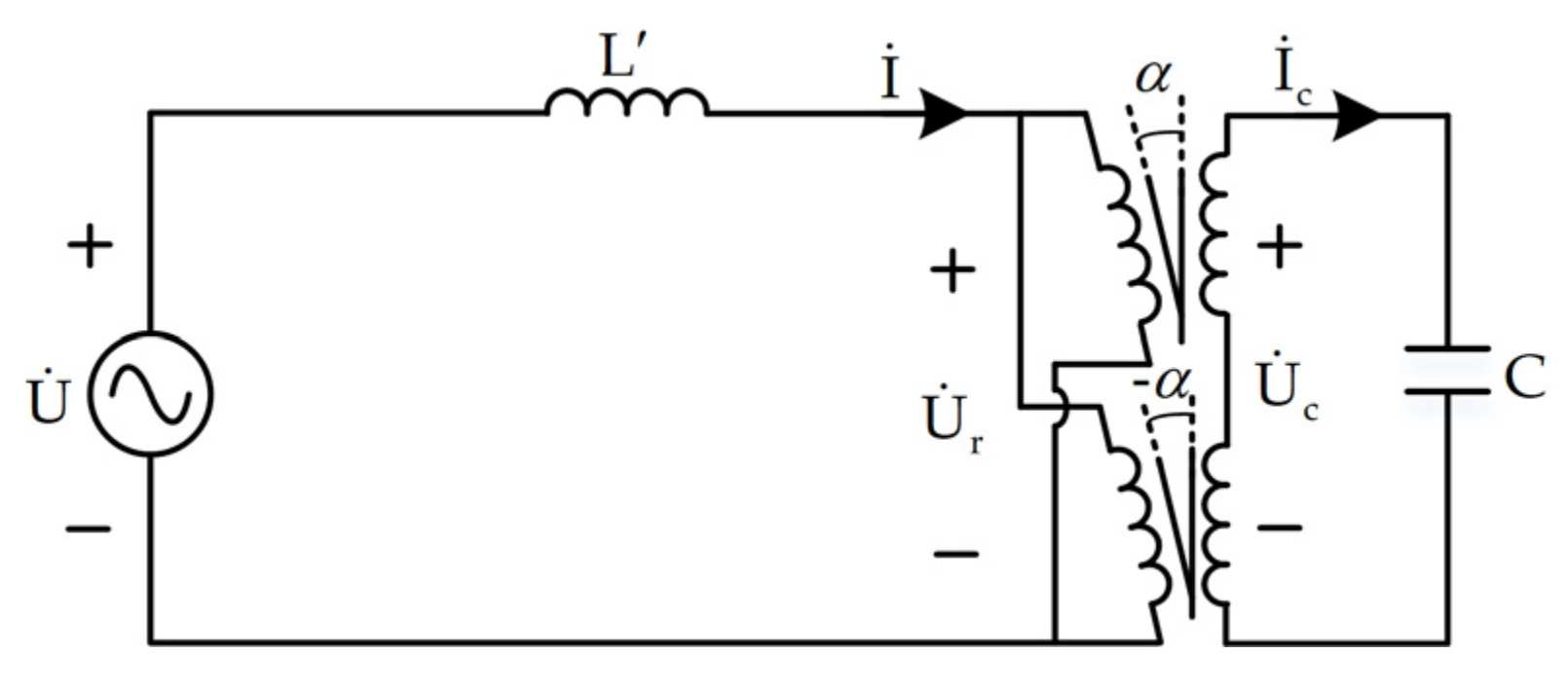
To explain the working principle of the EVC, the single-phase equivalent circuit of the EVC is established as shown in Figure 4. L’ is the equivalent filter inductance that considers the self-inductance of the RPSTs. , and are the EVC’s parallel point voltage, RPST’s primary side voltage, and compensation capacitor’s voltage, respectively. and are the compensation current and capacitor current, respectively. The reference directions of voltage and current are as shown in the figure.
To simplify the study, assume that the turns ratio of primary and secondary windings is 1. The KVL equation is written for the primary side of the circuit:
Since is in phase with the reference voltage phasor , their amplitudes Ur and U are taken when calculating the apparent power S. The later text also follows this method. S of single-phase EVC can be expressed as:
Therefore, the single-phase compensation reactive power is:
It can be seen from the Formula (6) that when U > Ur, Q > 0, EVC absorbs reactive power; when U < Ur, Q < 0, EVC emits reactive power. Hence, EVC can both absorb and emit reactive power, enabling flexible compensation of the reactive power required by the system.
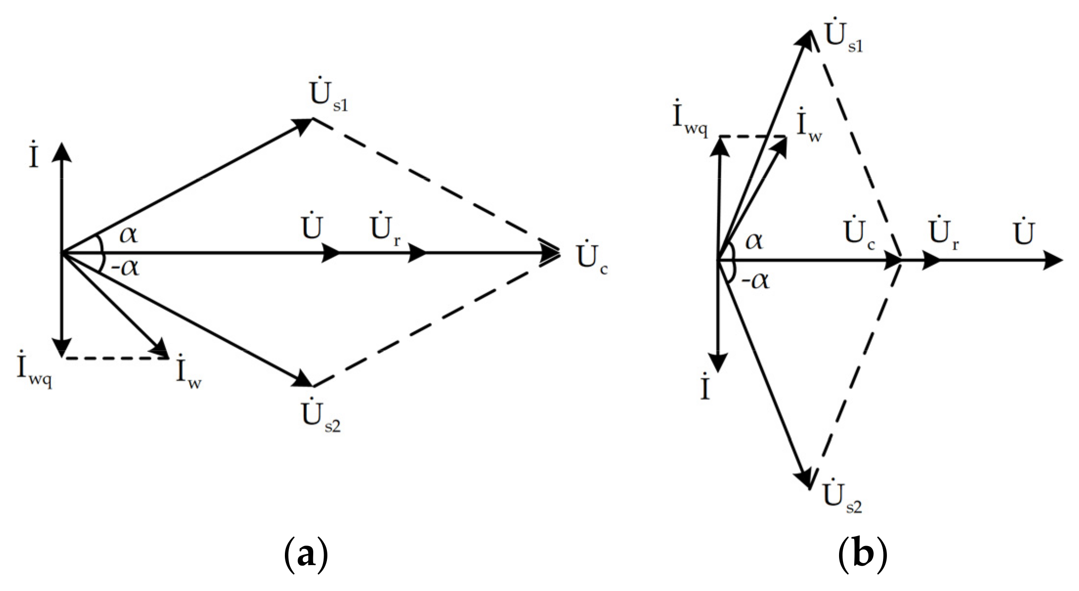
The phasor diagrams of the two ideal operating modes of the EVC are shown in Figure 5. The grid-side parallel point voltage is set as the reference phasor. and are the reactive component of the wind power side current and the compensation current of the EVC, respectively, which must satisfy to maintain the power factor of the grid side at 1. and are the secondary side voltages of the two RPSTs.
Figure 5a shows the ideal capacitive condition of EVC. At this time, the wind power system absorbs reactive power. The primary side voltage of RPST is greater than the parallel point voltage. The compensation current is ahead of the parallel point voltage . EVC presents pure capacitive characteristics on the grid side. Figure 5b shows the ideal inductive condition of EVC. At this time, the wind power system emits reactive power. The RPST primary side voltage is less than the parallel point voltage. The compensation current lags the parallel point voltage . EVC presents pure inductive characteristics on the grid side.
4. Parallel Steady-State Mathematical Model and Control Strategy of the EVC
4.1. Parallel Steady-State Mathematical Model of the EVC
The single-phase equivalent circuit diagram of the EVC connected to the power grid is shown in Figure 6. and are the primary side current of the two RPSTs. TRPST is the voltage transformation ratio of the RPSTs, which is set as 1 to simplify the calculation. α and −α are the phase shift angle of the two RPSTs. The preceding diagram does not consider system resistance loss.
In accordance with the transformer principle, the relationship between the primary and secondary side voltages of the two RPSTs can be expressed as:
On the basis of the principle of vector synthesis, the capacitor voltage is obtained by connecting the secondary windings in series as follows:
In the same manner, the current relationship can be obtained as follows:
From Equation (4), the compensation current of the EVC can be expressed as:
Knowing the capacitor voltage, the reactive power emitted by the capacitor can be obtained as:
According to the compensation current of EVC, the reactive power absorbed by the inductor is:
Thus, the reactive power compensated by the EVC to the grid can be expressed as:
Putting Equations (8) and (10) into Equation (13):
To simplify the calculation, let TRPST be equal to 1. Simplify further:
The latter is ignored due to . After approximate simplification, the relationship among EVC compensation reactive power, grid connection point voltage, primary side voltage and RPST phase shift angle can be obtained as follows:
4.2. Control Strategy
A control strategy of the EVC based on RPST is constructed. A diagram of the control strategy is shown in Figure 7.
The control strategy of the reactive power compensator is implemented in the dq rotating coordinate system. The grid-connected point voltage is fixed on the d axis through a phase-locked loop (PLL). The dq coordinate system rotates at the power grid fundamental angular velocity ω. Decompose Uabc into dq components in this coordinate system:
In the same way, Id, Iq, Icd and Icq can be obtained. The active and reactive power of EVC can be expressed as:
The main design idea of the power control outer loop is to dynamically adjust the reactive component of the secondary current according to the reactive power output by the EVC. To achieve the above purpose, the reactive power control loop can be designed as follows:
where Qref and Q are the reference value and actual value of reactive power of EVC, respectively. KP1 and KI1 are the proportional and integral parameters of the PI controller, separately.
The magnitude and phase of the secondary current phasor are:
where Icdref and Icd are the reference and actual values of the active component of the secondary current. Icqref and Icq are the reference and actual values of the reactive component of the secondary current. KP2 and KI2 are the proportional and integral parameters of the active current inner loop PI controller. KP3 and KI3 are proportional parameters and integral parameters of the reactive current inner loop PI controller.
The capacitance-voltage phasor can be expressed as:
The d-axis component of the capacitor voltage is:
The phase shift angle of RPST is:
In accordance with the reactive power control of the EVC shown in Figure 7, the control system realizes the tracking of compensation reactive Q to reactive command value Qref and secondary reactive current Icq to reactive current command value Icqref through the reactive power outer loop and reactive current inner loop, respectively. This article does not consider the control of the active part of EVC, so in the following analysis, icd = icdref = 0.
5. Simulation Analysis
The three-phase system model of the EVC with a rated voltage of 690 V and a bidirectional compensation capacity of 1 MVar is built in the MATLAB/Simulink simulation platform in accordance with Figure 3. Because the RPST adopts the structure of the wound asynchronous motor in practice, in order to accurately reflect the dynamic characteristics of the EVC, the wound asynchronous motor module is used to simulate the working process of the RPST in the simulation. The rotor speed of the asynchronous motor module is set to 0, and the rotation phase shift angle output by the control strategy is input to the asynchronous motor module. The regulation characteristics of EVC are tested using reactive load instead of wind power system.The simulation system parameters are provided in Table 1.
First, the compensation range of the EVC is tested. Then, the compensation effect of EVC is studied and analyzed in capacitive and inductive operating conditions, respectively.
5.1. Adjustment Range of the EVC
The adjustment range test of the EVC is illustrated in Figure 8. The EVC operates under maximum capacitive conditions with an initial rotor rotation angle of 0°. At this moment, the capacitor voltage is the highest, and the EVC sends out about 1 MVar of reactive power. The rotor rotation angle is adjusted to ±90° at 5 s and switched to the maximum inductive condition. At this moment, the capacitor voltage is close to 0 and the EVC absorbs about 1 MVar of reactive power from the grid. Since a certain margin is considered in the parameter design, the actual compensation range of EVC is slightly larger than ±1 MVar.
5.2. Adjustment Effect Analysis of the EVC
5.2.1. Capacitive Condition
To verify the adjustment effect of the EVC under capacitive condition, the reactive power command Qref is set to −1 MVar. At 0–1 s, the EVC has not yet been put into operation, and the required reactive power is provided by the grid. At this moment, the power factor of the grid side is 0.707. The three-phase voltage and current before compensation are presented in Figure 9a, where the voltage and current of the grid exhibit phase deviation and the current lags behind the voltage. The EVC is put into operation at 1 s to compensate for the inductive reactive power. After the adjustment time ts = 0.66 s, the power factor is increased from 0.707 to 1, and the overshoot σ is 0. The three-phase voltage and current after compensation and power factor are shown in Figure 9b,c, respectively. The tracking of the compensated reactive power Q to the reactive command value Qref is illustrated in Figure 9d. The EVC achieves full compensation for the inductive reactive power after a response time of about 0.7 s, and the steady-state error with the reactive power command value is 0. The secondary-side current component tracking is depicted in Figure 9e. The current reactive component Icq can achieve the tracking of the reactive current command value Icqref. Meanwhile, the current active component is extremely small and does not exceed the current limit.
5.2.2. Inductive Condition
To verify the adjustment effect of the EVC under inductive conditions, the reactive power command Qref is set to 1 MVar. At 0–1 s, the EVC has not yet been put into operation. At this moment, the power factor of the grid side is 0.707. The three-phase voltage and current before compensation are shown in Figure 10a, where the voltage and current of the grid exhibit phase deviation, and the current is ahead of the voltage. The EVC is put into operation at 1 s to compensate for the capacitive reactive power required by the system. After the adjustment time ts = 0.53 s, the power factor is increased from 0.707 to 1, and the overshoot σ = 0. The three-phase voltage and current after compensation and power factor are presented in Figure 10b,c, respectively. The tracking of the compensated reactive power Q to the reactive command value Qref is shown in Figure 10d. The EVC achieves full compensation for the capacitive reactive power after a response time of about 0.8 s, and the steady-state error with the reactive power command value is 0. The secondary-side current component tracking is depicted in Figure 10e. The current reactive component Icq can achieve the tracking of the reactive current command value Icqref. Meanwhile, the current active component is extremely small and does not exceed the current limit.
6. Experimental Verification
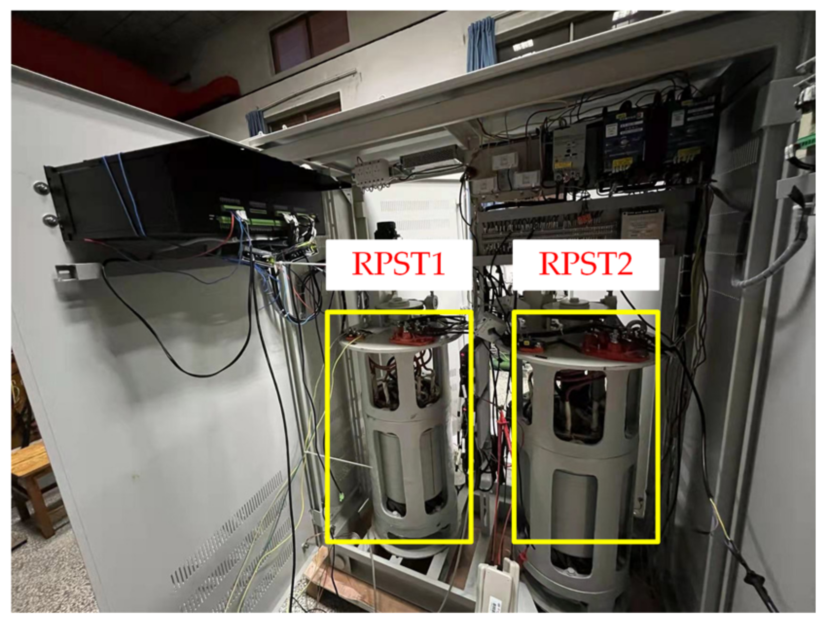
To further verify the validity of the EVC topology proposed in the current work, a 380 V EVC prototype experimental platform is built, as shown in Figure 11. The compensation capacitor is 380 V/6.6 kVar. An open-loop experiment was designed to test the bidirectional compensation range of the EVC by adjusting the phase shift angle of the two RPSTs to verify the effectiveness of the proposed topology.
The initial phase shift angle of the RPSTs is 90°, and the synthetic voltage is 0. Therefore, the reactive power emitted by the capacitor is 0, and the reactive power absorbed by the EVC reaches the maximum value. Then, the phase shift angle of both RPSTs is adjusted to 0°. At this point, the synthesized voltage reaches the maximum value and the EVC emits the maximum reactive power. It can be seen from Figure 12 that the compensation range of EVC can reach ±1 kVar. Figure 12a shows the phase shift angle of the RPSTs. Figure 12b shows the actual reactive power compensation range of the EVC.
7. Conclusions
An EVC based on RPST and suitable for wind power access is proposed in this study. The working principle of the EVC under two typical conditions, i.e., capacitive and inductive, is analyzed. The parallel steady-state mathematical model of the EVC is studied, and a dual closed-loop control strategy with good robustness and high control accuracy is proposed. The effectiveness of the proposed topology and control strategy is verified via simulation. The following conclusions are drawn.
- (1)
- This study proposes a new topology of a shunt reactive power compensation device by replacing the power switching tube bridge of an VSC with RPSTs, which exhibits the features of a simple structure, low costs, no need to provide a separate power supply and isolation transformer, high voltage, and large capacity. The proposed topology can meet the requirements of power systems with a high percentage of wind power for the precise adjustment of reactive power compensation equipment, economic cost, easy operation and maintenance, strong shock resistance, and good tolerance.
- (2)
- Applying the instantaneous reactive power theory, a double closed-loop control strategy for the EVC, including power external and current internal loop controls, is proposed in this work. This strategy exhibits the characteristics of robustness and high control accuracy.
- (3)
- It is verified by simulation that the EVC topology and control strategy proposed in this paper can be applied to the power system with reactive power fluctuation after wind power is connected. The EVC is capable of bidirectional, continuous, and large-capacity compensation. The EVC has the ability to compensate precisely within its rated regulation range, providing new ideas for reactive power compensation devices and their control strategies.
For the experiments, only the single-machine experiment on the EVC was carried out; the subsequent grid-connected experiments need to be further researched and verified.
Author Contributions
Conceptualization, Y.G., X.Y. and J.J.; methodology, Y.G., X.Y. and J.J.; software, Y.G.; validation, Y.G.; data curation, Y.G.; writing—original draft preparation, Y.G.; writing—review and editing, Y.G., W.A., B.Q., Y.W. and X.X. All authors have read and agreed to the published version of the manuscript.
Funding
This research was funded by general projects of the Beijing Natural Science Foundation (3212037); State Grid Hebei Province Science and Technology Project “Research and Application of Digital Precision Regulation Technology for Voltage and Flow of Xiong’an Urban Distribution Network” (SGHEDK00DYJS2000286).
Acknowledgments
The authors of the article appreciate the referees for their valuable suggestions, which contributes to improving the paper.
Conflicts of Interest
The authors declare no conflict of interest.
References
- Zhao, X.; Ma, X.; Chen, B.; Shang, Y.; Song, M. Challenges toward carbon neutrality in China: Strategies and countermeasures. Resour. Conserv. Recycl. 2022, 176, 105959. [Google Scholar] [CrossRef]
- Liu, Z.; Guo, J.; Wu, D.; Fan, G.; Ge, H. Two-phase collaborative optimization and operation strategy for a new distributed energy system that combines multi-energy storage for a nearly zero energy community. Energy Convers. Manag. 2021, 230, 113800. [Google Scholar] [CrossRef]
- Liu, J.; Zhou, Y.; Li, Y.; Lin, G.; Zu, W.; Cao, Y.; Qiao, X.; Sun, C.B.; Cao, Y.; Rehtanz, C. Modelling and analysis of radial distribution network with high penetration of renewable energy considering the time series characteristics. IET Gener. Transm. Distrib. 2020, 14, 2800–2809. [Google Scholar] [CrossRef]
- Liao, H. Review on Distribution Network Optimization under Uncertainty. Energies 2019, 12, 3369. [Google Scholar] [CrossRef] [Green Version]
- Von Appen, J.; Stetz, T.; Braun, M.; Schmiegel, A. Local voltage control strategies for pv storage systems in distribution grids. IEEE Trans. Smart Grid. 2014, 5, 1002–1009. [Google Scholar] [CrossRef]
- Aziz, T.; Ketjoy, N. PV penetration limits in low voltage networks and voltage variations. IEEE Access 2017, 5, 16784–16792. [Google Scholar] [CrossRef]
- Chen, S.X.; Eddy, Y.S.F.; Gooi, H.B.; Wang, M.Q.; Lu, S.F. A centralized reactive power compensation system for LV distribution networks. IEEE Trans. Power Syst. 2014, 30, 274–284. [Google Scholar] [CrossRef]
- Chen, B.; Zhang, C.; Zeng, W.; Xue, G.; Tian, C.; Yuan, J. Electrical magnetic hybrid power quality compensation system for V/V traction power supply system. IET Power Electron. 2015, 9, 62–70. [Google Scholar] [CrossRef]
- Pijarski, P.; Kacejko, P. Methods of simulated annealing and particle swarm applied to the optimization of reactive power flow in electric power systems. Adv. Electr. Comput. Eng. 2018, 18, 43–48. [Google Scholar] [CrossRef]
- Wan, Y.; Murad, M.A.A.; Liu, M.; Milano, F. Voltage frequency control using SVC devices coupled with voltage dependent loads. IEEE Trans. Power Syst. 2019, 34, 1589–1597. [Google Scholar] [CrossRef]
- Duan, C.; Fang, W.; Jiang, L.; Niu, S. FACTS devices allocation via sparse optimization. IEEE Trans. Power Syst. 2016, 31, 1308–1319. [Google Scholar] [CrossRef] [Green Version]
- Ko, W.H.; Gu, J.C. Design and application of a thyristor switched capacitor bank for a high harmonic distortion and fast changing single-phase electric welding machine. IET Power Electron. 2016, 9, 2751–2759. [Google Scholar] [CrossRef]
- Hemmati, R.; Faraji, H.; Beigvand, N.Y. Multi objective control scheme on DFIG wind turbine integrated with energy storage system and FACTS devices: Steady-state and transient operation improvement. Int. J. Electr. Power Energy Syst. 2022, 135, 107519. [Google Scholar] [CrossRef]
- Das, S.; Chatterjee, D.; Goswami, S.K. Tuned-TSC based SVC for reactive power compensation and harmonic reduction in unbalanced distribution system. IET Gener. Transm. Distrib. 2018, 12, 571–585. [Google Scholar] [CrossRef]
- Velásquez, R.M.A.; Lara, J.V.M. Harmonic failure in the filter of static var compensator. Eng. Fail. Anal. 2020, 107, 104207. [Google Scholar] [CrossRef]
- Farivar, G.; Townsend, C.; Hredzak, B.; Pou, J.; Agelidis, V. Passive reactor compensated cascaded H-bridge multilevel LC-StatCom. IEEE Trans. Power Electron. 2017, 32, 8338–8348. [Google Scholar] [CrossRef] [Green Version]
- Abd-Elazim, S.M.; Ali, E.S. Imperialist competitive algorithm for optimal STATCOM design in a multimachine power system. Int. J. Electr. Power Energy Syst. 2016, 76, 136–146. [Google Scholar] [CrossRef]
- Abd-Elazim, S.M.; Ali, E.S. Optimal location of STATCOM in multimachine power system for increasing loadability by cuckoo search algorithm. Int. J. Electr. Power Energy Syst. 2016, 80, 240–251. [Google Scholar] [CrossRef]
- Wei, T.; Mao, C.; Lu, J.; Wang, D.; Wang, Q.; Wu, W. Low cost hybrid reactive power compensator using coordination control strategies. IET Gener. Transm. Distrib. 2016, 10, 1805–1814. [Google Scholar] [CrossRef]
- Shuai, Z.; Luo, A.; Shen, Z.J.; Zhu, W.; Lv, Z.; Wu, C. A dynamic hybrid var compensator and a two-level collaborative optimization compensation method. IEEE Trans. Power Electron. 2009, 24, 2091–2100. [Google Scholar] [CrossRef]
- Li, M.; Li, W.; Zhao, J.; Chen, W.; Yao, W. Three-layer coordinated control of the hybrid operation of static var compensator and static synchronous compensator. IET Gener. Transm. Distrib. 2016, 10, 2185–2193. [Google Scholar] [CrossRef]
- Wang, L.; Chi-Seng, L.; Man-Chung, W. A hybrid-STATCOM with wide compensation range and low DC-link voltage. IEEE Trans. Ind. Electron. 2016, 63, 3333–3343. [Google Scholar] [CrossRef]
- Rahmani, S.; Hamadi, A.; Al-Haddad, K.; Dessaint, L.A. A combination of shunt hybrid power filter and thyristor-controlled reactor for power quality. IEEE Trans. Ind. Electron. 2013, 61, 2152–2164. [Google Scholar] [CrossRef]
- Wang, L.; Lam, C.S.; Wong, M.C. Hybrid structure of static var compensator and hybrid active power filter (SVC//HAPF) for medium-voltage heavy loads compensation. IEEE Trans. Ind. Electron. 2018, 65, 4432–4442. [Google Scholar] [CrossRef]
- Hu, P.; Guerrero, J.M.; He, Z. Design and analysis of a transformerless STATCOM based on hybrid cascaded multilevel converter. Int. J. Electr. Power Energy Syst. 2018, 104, 694–704. [Google Scholar] [CrossRef] [Green Version]
- Zhang, Y.; Wang, Y.; Zhang, D.; Chen, X.; Gong, C. Broadband Impedance Shaping Control Scheme of MMC-based STATCOM for Improving the Stability of the Wind Farm. IEEE Trans. Power Electron. 2021, 36, 10278–10292. [Google Scholar] [CrossRef]
- Lai, J.; Yin, X.; Zhang, Z.; Wang, Z.; Yin, X. System modeling and cascaded passivity based control for distribution transformer integrated with static synchronous compensator. Int. J. Electr. Power Energy Syst. 2019, 113, 1035–1046. [Google Scholar] [CrossRef]
- Wang, C.; Yin, X.; Zhe, Z.; Wen, M. A Novel compensation technology of static synchronous compensator integrated with distribution transformer. IEEE Trans. Power Deliv. 2013, 28, 1032–1039. [Google Scholar] [CrossRef]
- Larsen, E.V. Power Flow Control with Rotary Transformers. U.S. Patent 5,841,267, 24 November 1998. [Google Scholar]
- Haddadi, A.M.; Kazemi, A. Optimal power flow control by rotary power flow controller. Adv. Electr. Comput. Eng. 2011, 11, 79–86. [Google Scholar] [CrossRef]
Figure 1.
Wiring diagram of RPST.

Figure 2.
Windings position and voltage relationship: (a) Windings position; (b) Voltage relationship.
Figure 2.
Windings position and voltage relationship: (a) Windings position; (b) Voltage relationship.

Figure 3.
Topology of the EVC based on RPST.

Figure 4.
Single-phase equivalent circuit diagram.

Figure 5.
Phasor diagram of two ideal operating modes. (a) capacitive condition; (b) inductive condition.
Figure 5.
Phasor diagram of two ideal operating modes. (a) capacitive condition; (b) inductive condition.

Figure 6.
System single-phase equivalent circuit.

Figure 7.
Control strategy diagram of the EVC.

Figure 8.
Adjustment range.

Figure 9.
Simulation results of the adjustment effect of the EVC under capacitive condition: (a) The three-phase voltage and current before compensation; (b) The three-phase voltage and current after compensation; (c) Power factor; (d) Reactive power; (e) The secondary-side currents.
Figure 9.
Simulation results of the adjustment effect of the EVC under capacitive condition: (a) The three-phase voltage and current before compensation; (b) The three-phase voltage and current after compensation; (c) Power factor; (d) Reactive power; (e) The secondary-side currents.

Figure 10.
Simulation results of the adjustment effect of the EVC under inductive condition: (a) The three-phase voltage and current before compensation; (b) The three-phase voltage and current after compensation; (c) Power factor; (d) Reactive power; (e) The secondary-side currents.
Figure 10.
Simulation results of the adjustment effect of the EVC under inductive condition: (a) The three-phase voltage and current before compensation; (b) The three-phase voltage and current after compensation; (c) Power factor; (d) Reactive power; (e) The secondary-side currents.


Figure 11.
Test prototype.

Figure 12.
Single-machine verification results: (a) Phase shift angle of the RPSTs; (b) Reactive power compensation range of the EVC.
Figure 12.
Single-machine verification results: (a) Phase shift angle of the RPSTs; (b) Reactive power compensation range of the EVC.


Table 1.
Simulation of system parameters.
| Parameter | Value |
|---|---|
| Power voltage es/V | 690 |
| Power Equivalent Impedance Zs/Ω | 0.01 + j1 × 10−5 |
| Inductance L/mH | 0.11 |
| RPST rated capacity/MVA | 2 |
| RPST rated voltage/V | 690 |
| RPST stator side impedance (pu) Zs | 0.01 + j0.11 |
| RPST rotor side impedance (pu) Zr | 0.01 + j0.11 |
| RPST magnetizing inductance (pu) Lm | 3.36 |
| Capacitance C/mF | 3.68 |
| Scale factor of power outer-loop controller Kp_Q | 0.1 |
| Integral factor of power outer-loop controller Ki_Q | 3 |
| Scale factor of active current controller Kp_d | 0.1 |
| Integral factor of active current controller Ki_d | 20 |
| Scaling factor of reactive current controller Kp_q | 0.1 |
| Integral factor of reactive current controller Ki_q | 20 |
Publisher’s Note: MDPI stays neutral with regard to jurisdictional claims in published maps and institutional affiliations. |
© 2022 by the authors. Licensee MDPI, Basel, Switzerland. This article is an open access article distributed under the terms and conditions of the Creative Commons Attribution (CC BY) license (https://creativecommons.org/licenses/by/4.0/).
Share and Cite
MDPI and ACS Style
Yan, X.; Guo, Y.; Jia, J.; Aslam, W.; Qi, B.; Wang, Y.; Xu, X. An Electromagnetic Var Compensator Suitable for Wind Power Access and Its Control Strategy. Energies 2022, 15, 5572. https://0-doi-org.brum.beds.ac.uk/10.3390/en15155572
AMA Style
Yan X, Guo Y, Jia J, Aslam W, Qi B, Wang Y, Xu X. An Electromagnetic Var Compensator Suitable for Wind Power Access and Its Control Strategy. Energies. 2022; 15(15):5572. https://0-doi-org.brum.beds.ac.uk/10.3390/en15155572
Chicago/Turabian StyleYan, Xiangwu, Yan Guo, Jiaoxin Jia, Waseem Aslam, Bingbao Qi, Yang Wang, and Xiaolin Xu. 2022. "An Electromagnetic Var Compensator Suitable for Wind Power Access and Its Control Strategy" Energies 15, no. 15: 5572. https://0-doi-org.brum.beds.ac.uk/10.3390/en15155572
Note that from the first issue of 2016, this journal uses article numbers instead of page numbers. See further details here.