1. Introduction
In 2017, wind power generation accounted for 5.6% of global energy demand and showed an increasing trend [
1]. A doubly fed induction generator (DFIG) can realize the decoupling of active- and reactive-power control, and has become one of the mainstream models of wind farms at present [
2]. However, a problem is that the rotor speed of the DFIG cannot respond to changes in system frequency. This leads to a decrease in the equivalent rotational inertia of the system, which will reduce the safety of the power grid, thus increasing its potential risks [
3]. The United Kingdom blackout accident that occurred on 9 August 2019, occurred because during the system fault, the rotor speed of the DFIG could not respond to the change in system frequency, resulting in excessive rotor current, which caused the wind turbines of the Hornsea Wind Farm to go off-grid at a large-scale [
4].
The stability of motors has always been an important problem to be solved urgently in electric power research, and the excitation control of generators has attracted great attention from experts and scholars. One study [
5] compares the dynamic models of constant-speed and variable-speed induction generators, and analyzes the corresponding dynamic characteristics when there is power grid disturbance. When a three-phase short-circuit fault occurs, the dynamic characteristics of generator excitation system are analyzed in reference [
6], the characteristics of excitation models are compared, and the main factors affecting the stability of excitation model system are deeply discussed. With the further research on excitation control systems, the authors in [
7], based on nonlinear control theory, optimize a generator excitation system, use particle swarm optimization algorithm to optimize the phase parameters of a generator controller, put forward the design of a nonlinear super-spiral synovial excitation controller by output feedback, continuously enhance the stability of the system, and give suggestions to stabilize the system speed accordingly. The study in [
8] analyzes the shortcomings of particle swarm optimization, and adopts an improved particle swarm optimization algorithm combining crossover strategy and adaptive inertia weight strategy to improve the control of a synchronous generator excitation control system.
With the further development of research, one study [
9] proposed that, after adopting an AC excitation generator, due to the effect of AC excitation, the generator can keep synchronism with the system even if the generator rotor runs asynchronously. Additionally, because doubly fed induction generators can surpass the limitation of synchronous generators and realize asynchronous synchronous operation, the research on excitation control of corresponding generators has also developed rapidly. According to the power angle-characteristic equation of DFIGs in the literature [
10], it is concluded that DFIGs are determined by the rotor excitation current, so it can be concluded that DFIGs can change the generator rotor speed or active power by changing the excitation current frequency to achieve asynchronous stable operation. Another study [
11] puts forward a new excitation control method, which does not need to control the parameters of the motor, and is of great significance for eliminating the influence caused by the change in the speed of the prime mover. In addition, with the development of a power network, the complex working conditions it faces are increasing gradually. When three-phase short-circuit fault occurs in power network voltage, the rotor voltage and current of doubly fed induction generators will increase significantly [
12]. For the influence caused by a light voltage drop, the method of demagnetization control can be adopted, and the DC component of the stator flux can be attenuated by a crossing operation, so as to achieve the effect of limiting voltage drop [
13]. Through the above research, the rotor speed and active power output of doubly fed induction generators can be adjusted by excitation control, which lays a foundation for further digging into the huge inertia kinetic energy support of doubly fed induction generators.
In this paper, taking advantage of the asynchronous and synchronous operation of doubly fed induction generators, so that the speed of the generator can be controlled by excitation, the transient change process of doubly fed induction generators during three-phase short circuit is analyzed in principle, and the “active power transient frequency characteristic” of doubly fed wind generators is put forward according to its frequency characteristic curve. Through simulation and experiments, a single machine-infinite bus system platform with a doubly fed wind turbine is built, and it is verified that this unit is beneficial to motor stability under its unique control mode, thus improving the stability of the whole system.
3. Active Transient Frequency Characteristics of Doubly Fed Induction Generator
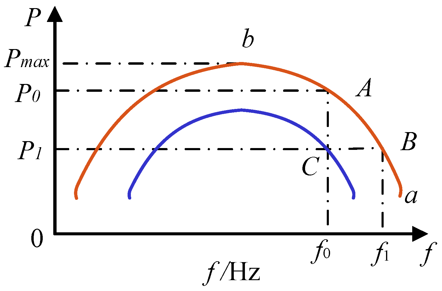
According to the frequency characteristics of the useful power of the generator, the relationship between the mechanical power of the generator and the rotor speed without automatic speed regulation system can be obtained:
Among them, all the above variables are nominal values,
c1,
c2,
d1,
d2 are constants, usually
c1 = 2
c2,
d1 = 2
d2 and Formula (2) can be expressed by the curve in
Figure 1.
Mechanical power is the product of torque and angular velocity, which means that these are two main factors affecting mechanical power. As shown in
Figure 1, when the speed is very low, even if the torque on the impeller is increased, it does not mean that the mechanical power can be increased, because at this time, the angular velocity is not increased. With the increasing angular velocity, the impeller speed is gradually accelerated; at this time, the angular velocity makes it difficult to track the impeller speed well, and the mechanical power will be reduced accordingly. Therefore, when the generator runs under rated conditions, the mechanical power reaches the maximum, that is, the product of torque and angular velocity is the maximum. According to the static frequency characteristics of the comprehensive load of the system, the generator can only run stably in the ab section of the curve shown in
Figure 1.
When the generator suffers from interference such as a short circuit, as the mechanical energy input to the DFIG is inconsistent with the electrical energy output, the rotating speed of the rotor will increase. At this time, as shown in
Figure 1, the rotor will move from point A to point B. At this time, the rotating speed of the motor will increase continuously. However, with the increasing rotating speed of the motor, the expected air inlet speed of the motor does not match, and it is difficult to track the rotating speed of the impeller, so the torque will decrease, which finally shows that the mechanical power decreases, and the acceleration process of the rotor is accompanied by the conversion of kinetic energy. Therefore, there must be a dynamic equilibrium point on the curve of segment ab shown in
Figure 1, which makes the output active power of the generator set equal to the input mechanical power, and is temporarily identified as point B. When the transient process is over, the speed can be set to the initial value by using the governor automatic adjustment, that is, the speed can be restored from point B to point C. In the process of adjustment, the full transient process should be satisfied: the acceleration area is less than or equal to the deceleration area, so as to ensure the stability of the power supply system and the effective control of the whole transient process. The performance of the governor itself and its inertia will not affect the active-power characteristics of the prime mover.
The power angle-characteristic equation of the DFIG [
10] is
The DFIG power angle-characteristic equation is similar to that of the traditional synchronous generator, but the difference is that the no-load electromotive force
Eq’ is determined by the rotor excitation current formed by the combined voltage of the external given excitation voltage
Ur and the rotor slip-induced electromotive force
Er [
10]. So, it can be concluded that the DFIG can change the generator rotor speed or active power by changing the excitation current frequency to achieve asynchronous stable operation. Therefore, in the transient process, the doubly fed induction generator can make the rotor of the generator run asynchronously due to AC excitation, and the DFIG keeps synchronization with the system. This characteristic is called the “active power transient frequency characteristic” of the doubly fed induction generator. In
Figure 2, the abscissa is the rotor speed, and the ordinate is the active power. When it is at point A, the purpose of the active-power transient frequency characteristic is to reduce the active power by increasing the rotor speed of the DFIG, and the rotor current I
r value corresponding to the active power will decrease. Once the rotor current decreases, the fault ride-through can be realized.
In the case of short-circuit fault, the changes in the synchronous generator and doubly fed induction generator can be compared. If the generator is connected with the system through a transformer through a double-circuit line, the system runs stably at point a in
Figure 3 (the power angle is
δ0), and the output power P
0 of the synchronous generator is consistent with the output power P
T of the prime mover. When a short-circuit fault occurs, according to the power characteristic curve, the power output of the synchronous unit immediately drops to P
II. Because of the inertia of the generator rotor, the angle
δ0 relative to the bus voltage of the infinite system does not change, so the output power of the synchronous machine suddenly changes from the operating point a to the operating point b, but at this time, the mechanical power P
T output by the prime mover does not change, so excess power will be generated in the system, and the more serious the fault situation, the more obvious the amplitude reduction in the P
II power curve. Under a three-phase short-circuit fault, the P
II curve is a straight line with a zero ordinate. Under the action of excess torque, the rotor speed of the generator accelerates, which increases correspondingly compared with the synchronous speed and the relative angle δ, and the operating point b moves to the point c. If the fault persists, the generator will continue to accelerate due to the excess torque, which will eventually lead to the system being out of step.
In case of a sudden system three-phase short circuit, the faulty line should be eliminated in time. After the relay protection device acts quickly, the power characteristic curve of the generator changes to P
III, which suddenly changes from point c to point e, and the rotor speed is restrained because the output power of the generator is greater than the mechanical power of the prime mover. However, because the rotor speed is larger than the synchronous speed at this time, the relative angle δ increases accordingly. If the braking point of the synchronous speed is point f, δ will not increase at this time. However, as the electromagnetic power is greater than the mechanical power at this time, the rotating speed of the rotor decreases continuously, and the relative angle δ also decreases, and the operating point f will move in the directions of operating points e and k. When point k is not reached, the rotor speed decreases continuously and is lower than the synchronous speed. When the speed of the rotor reaches point k, δ will also decrease due to the low speed of the rotor. When the speed exceeds point k, the electromagnetic power will be lower than the mechanical power, and then the speed of the rotor will be improved. Therefore, there will be oscillation at the operating point, and finally, the generator will stop at operating point k due to energy loss and damping. The corresponding change curve is shown in
Figure 4.
In case of extreme working conditions, the rotor speed reaches a very high speed before the fault line is cut off. Then, when the fault is cut off and reaches point f, as shown in
Figure 3, the rotor speed will still be higher than the synchronous speed and will continue to reach point h. In the absence of full recovery, once the operating point crosses point h, the torque acceleration will further increase the speed, the acceleration will increase with it, and the relative angle δ will also continuously increase, resulting in the final system instability, as shown in
Figure 5.
The difference between the doubly fed induction generator and the synchronous generator studied in this paper is:
The doubly fed induction generator can satisfy the power angle-characteristic equation at any slip rate. Adjusting the excitation current frequency ensures
Ne +
Nm and No are the same, and the relative angle δ can remain in the k→h domain shown in
Figure 3. By absorbing its acceleration energy in the process of δ
0→δ
c, the residual energy Δ
P (Δ
P = acceleration area–deceleration area) can be transformed into the kinetic energy of the rotor.
The doubly fed induction generator has “active power transient frequency characteristics”. As shown in
Figure 6, when the rotor speed exceeds the moderate value, the mechanical power P
T of the prime mover will decrease. When the deceleration area defg is less than the acceleration area abcd, while the generator rotor continues to accelerate, the mechanical power P
T input to the generator decreases, as shown in
Figure 6, which is equivalent to reducing the acceleration area and increasing the deceleration area, thus reaching a new balance point.
When a three-phase short-circuit fault suddenly occurs in one circuit of the receiving end, the imbalance between the mechanical power input to the generator and the active power output at this time leads to an increase in the rotor speed. According to the flywheel effect of rotor kinetic energy, the rotating speed of the synchronous generator sets changes in the range of 0.96–1 pu during the system frequency modulation, in which 0.96 pu corresponds to the rotating speed of the synchronous machine when the system frequency is at the lower limit of 48 Hz, and the maximum rotor kinetic energy that can be absorbed by synchronous generator sets is:
where
J is the moment of inertia of the unit,
E0 is the initial speed, the rotor kinetic energy corresponds to
ω0, and
E1 is the rotor kinetic energy corresponding to the rotor speed
ω1 after the unit participates in frequency modulation. Comparing a 2 MW doubly fed wind turbine with a synchronous generator with the same capacity, the moment of inertia of the doubly fed wind turbine is
, the inertia time constant of the synchronous generator is
H = 10 s, and the maximum rotor kinetic energy absorbed by the synchronous generator is 1.568 MJ by substituting into Formula (6). For doubly fed wind turbines, the absorbed rotor kinetic energy is related to the rotational speed of the wind turbine in steady-state operation, and the operating range of the rotor rotational speed is generally 0.7–1.2 pu. By substituting it into Formula (5), the absorbed rotor kinetic energy of the wind turbine at different rotational speeds can be obtained. It can be seen that at the lowest speed, the wind turbine can absorb 1.57 MJ of rotor kinetic energy, even at a lower speed (0.8 pu), which is equivalent to that of a synchronous generator, so the DFIG can increase the rotor speed to absorb a large amount of kinetic energy in a short time. When the DFIG drops at 10% and 15% rated power, the transient power support time provided by the absorbed rotor kinetic energy is shown in
Table 1. Even at 15% rated power, the wind turbine can provide no less than 5 s of transient support capacity.
From the above analysis, it can be known that due to the “active power transient frequency characteristics” and the “flywheel effect” of the rotor, the generator meets the requirement that the acceleration area is less than or equal to the deceleration area in the transient time domain, which is expected to realize the stable control of the power system in the transient time domain.
4. Characteristic Simulation and Experimental Verification of DFIG
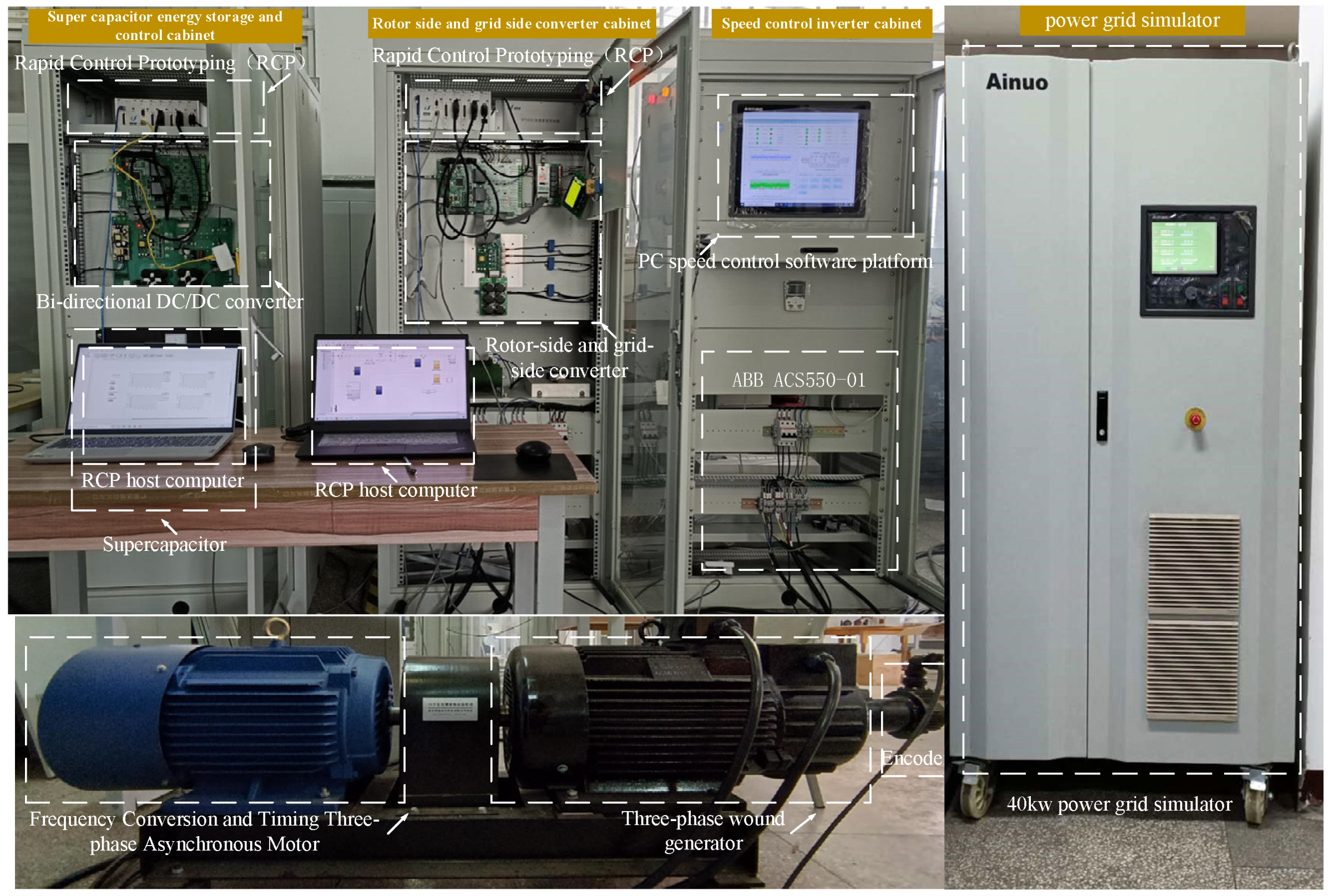
In this paper, a simulation platform of doubly fed wind power generation (10 kW/380 V) is used to verify the correctness of the analysis of the above-mentioned “active power transient frequency characteristics” of doubly fed induction generators, which are mainly composed of a monitoring console, converter cabinet of prime mover speed regulation, converter cabinet of the rotor side and grid side of a doubly fed generator, 40 kW bidirectional power-grid simulator cabinet, 15 kW asynchronous motor and a 10 kW doubly fed generator. The test system structure is shown in
Figure 7. The controller adopts the YXSPACE-SP2000 Rapid Control Prototype Controller (RCP), which can convert the control algorithm under MATLAB-Simulink into input and output switch control quantity and input and output analog regulation quantity, and can complete the actual hardware control.
When the doubly fed induction wind turbine is connected to the grid, and the wind speed is 7 m/s–12 m/s, the simulation system will be disturbed, which will then be transformed into the target value for adjusting the excitation current frequency. We recorded the active power and other state quantities of DFIG output, as shown in
Table 2,
Table 3,
Table 4,
Table 5,
Table 6 and
Table 7.
The active-power transient frequency characteristics of the doubly fed induction generator at different wind speeds are shown in
Figure 8. Take the wind speed of a wind turbine running in the maximum power tracking area as an example. At this time, the rotor speed of the doubly fed induction generator is 1212 r/min, the excitation current frequency is reduced from 9.59 Hz to −10.13 Hz, the rotor speed is increased from 1212 r/min to 1804 r/min, and the active output power of the doubly fed induction generator is reduced from 0.187 pu to 0.055 pu, that is, at the wind speed of 8 m/s. The relationship curve can be seen in
Figure 8. When the synchronous speed of the doubly fed generator fluctuates by 20%, the active power of the generator will change by 70.6%. Considering the response capability of the AC excitation control system, this characteristic can improve the stability of power system, thus realizing the stable control of the transient power system.
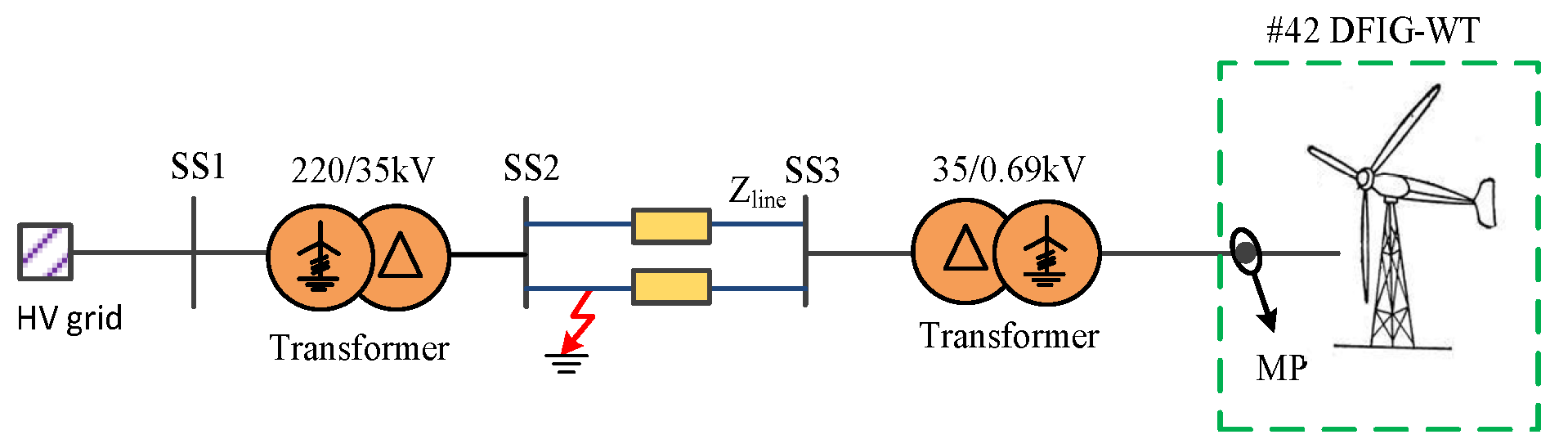
In order to further verify the universality of the application scenario of the above-mentioned doubly fed induction generator with this characteristic, aiming at the single-machine infinite-bus system, this paper establishes a grid-connected system simulation platform based on a doubly fed wind turbine based on MATLAB/Simulink. Its system wiring diagram is shown in
Figure 9 and its main control is shown in
Figure 10. As shown in
Figure 9, in normal operation, the doubly fed induction generator sends power to the infinite system through transformers and double-circuit lines. The wind turbine runs normally at 8 m/s, and when the time T is 200 s, a three-phase short-circuit fault occurs, and the relay protection device acts quickly to protect the system circuit. The specific control in
Figure 10 is such that when the rotor current reaches the critical value of 1.3 pu, the simulation system automatically switches from the conventional control to the active transient frequency characteristic control, which automatically increases the rotor speed so as to follow the relationship between the transient power and the speed in
Figure 1. The active power output by the DFIG will decrease until it reaches the normal value, and the rotor speed will not increase at this time, thus completing the entire control process.
Figure 11 shows the rotor speed curves of the doubly fed induction generator under conventional control and the active transient frequency characteristics’ comparison. When T is less than 200 s in section A-B in the figure, the rotor speed is stable at 0.8 pu. At point B, when time T is 200 s, a three-phase short-circuit fault occurs, and the relay protection device acts quickly to protect the system circuit. By comparing the B-D section with conventional control and the B-C section with active-power transient frequency characteristics, it can be clearly found that under conventional control, after the primary circuit is disconnected, the speed of the doubly fed induction generator loses stability and increases to the maximum value at 1.2 pu. However, after adopting the active-power transient frequency characteristic, the rotor speed increases slightly and then stabilizes at 0.8 pu, which is beneficial to the stability of the system.
Figure 12 shows active power output curves of the doubly fed induction generator under conventional control and the active transient frequency characteristics’ comparison. When T is less than 200 s in section A–B in the figure, the active power output of the generator is stable at 0.18 pu. At point B, when time T is 200 s, a three-phase short-circuit fault occurs, and the relay protection device acts quickly to protect the system circuit. By comparing the B–D section with conventional control and the B–C section with active-power transient frequency characteristics, it can be clearly found that under the conventional control, the output active power drops to zero, and the doubly fed induction generator is off-grid. However, by adopting the active-power transient frequency characteristic, the active power remains at 0.18 pu, which is very beneficial to the stability of the system.
Figure 13 shows the power angle–power characteristic curve of the doubly fed induction wind turbine at a wind speed of 8 m/s. The initial stable operating point of the DFIG is point a (the power angle is
δ0), and when a three-phase short-circuit fault occurs in one circuit, the amplitude of the P
II power curve drops to zero. Under the action of excess torque, the rotor speed of the generator increases, and its relative speed and relative angle continue to increase, moving from operating point b to operating point c. At 0.05 s, when the short-circuit fault occurs, the relay protection device cuts off the fault line, and the power angle–power characteristic curve of the doubly fed induction generator changes to P
III, and the operating point c changes to operating point e. At this time, the output power of the generator is larger, so that the effect of restraining the rotor speed can be achieved. Then, the rotor speed decreases, and the power angle δ continues to decrease. The operating point moves along the curve P
III shown in
Figure 13 in the direction of point k. Finally, due to the energy loss and damping in the oscillation process, it stays at a new dynamic equilibrium point, that is, the intersection point between curve P
III and curve P
T at rotor speed ωr = 0.8 pu.
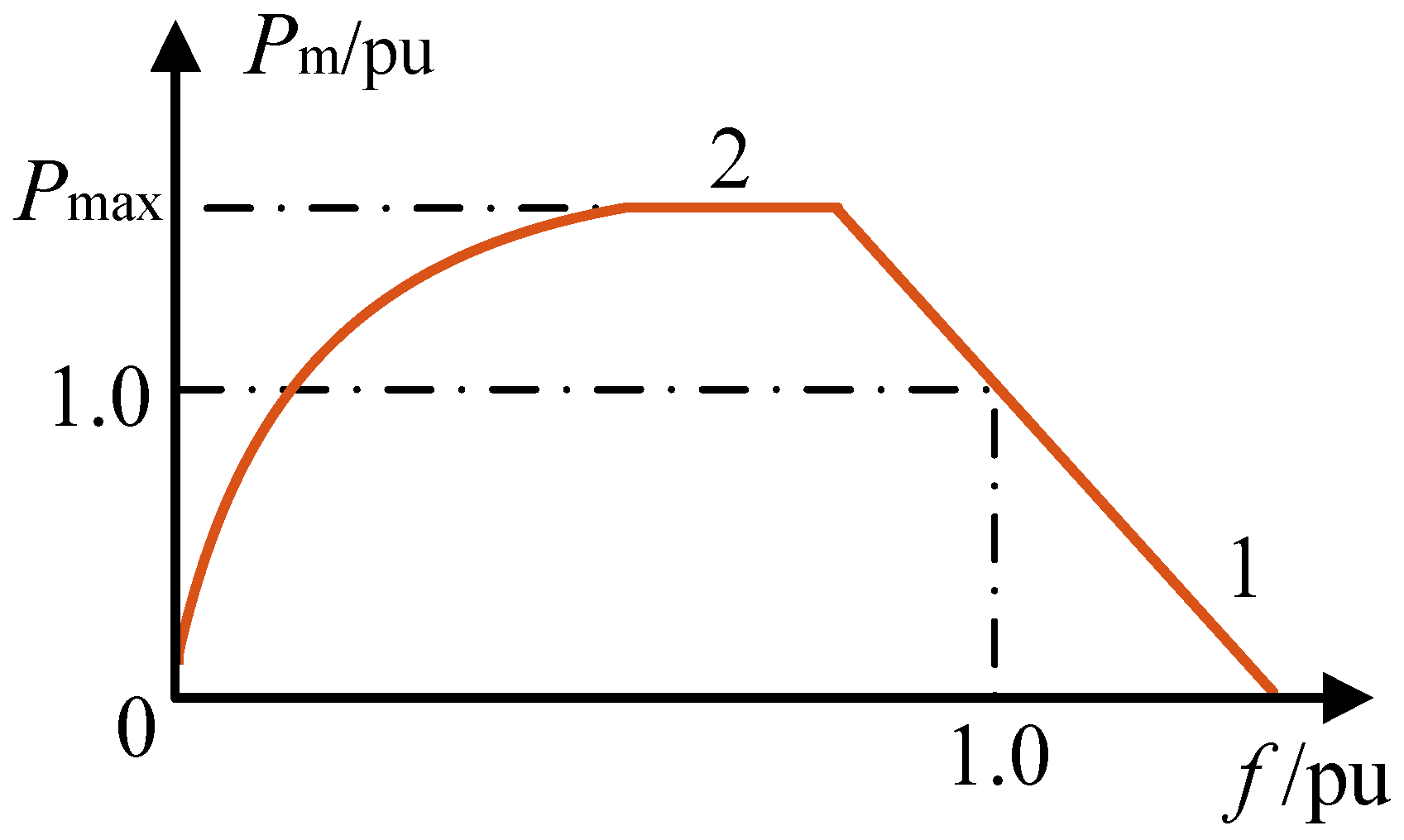
The transient time-domain stability of the doubly fed induction generator is not only related to the magnitude of disturbance and the time to withstand disturbance, but also related to the system structure, power-flow situation, impedance and inertia of the generator, and many other factors, such as excitation regulator (AVR) and governor (GOV) automatic control device. In order to highlight the key research contents of this paper, only the influence of the whole transient process when the wind turbine not equipped with a governor is considered. Therefore, based on the curve shown in
Figure 1, it is approximately considered that the slope of section 1–2 of the curve is unchanged, which can be simplified as shown in
Figure 13. The slope of the straight line is
KG = Δ
PG/Δf, that is, the power–frequency characteristic curve of the wind turbine, which can also be expressed by standard values, in which
KG* = 33.3~20.
Its electromechanical motion equation can be expressed as:
TJ is the inertia time constant of the doubly fed induction generator, and
Tm and
Te are its mechanical torque and electromagnetic torque, respectively. When the torque
T is expressed by power, the electromechanical motion equation becomes:
It is known that the inertia time constant
TJ of the generator usually takes 8–16 s, the unit with a small capacity takes a larger value, and the unit with a large capacity takes a smaller value. Under this time constant, the prime mover accounts for about 60%. Additionally, the mechanical power Pm of the prime mover is represented by the simplified straight line in
Figure 14, such that:
where
ω0 and
Pm0 are the rotational speed and corresponding mechanical power values in the initial operation state, respectively. With Formula (8), the electromechanical motion equation of the doubly fed induction generator can be transformed into:
Set the initial operating state as the rated operating state, that is, Pm0 = PmN = 1, ω0 = ωN = 1, Pe0 = PeN = 1.
Bring these values into Formula (10) and obtain:
Take the wind speed of 8 m/s as an example. When the system fails, the mechanical energy input into the generator is unbalanced with the electric energy sent by the generator to the system, and the generator will deviate from the synchronous point.
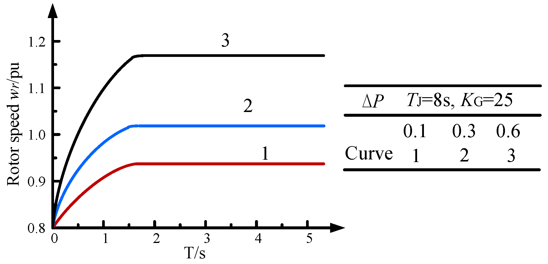
Take the transition process when TJ = 8 s and KG = 25, and the transient power step is ΔP = 0.1, 0.3 and 0.6. Next, the transient process of the doubly fed induction generator is solved iteratively when the system has a permanent fault and the transient power step change ΔP = 0.1, 0.3 and 0.6, respectively.
It can be seen from
Figure 15 that when the system is grounded or three-phase suddenly short-circuited and the rated power difference of the doubly fed induction generator is 10%, 30% and 60%, the generator rotor will accelerate, and the acceleration process will change exponentially. After reaching a certain value, the generator will finally run stably at this speed value. At this time, if the speed control system works, the manner of damper (or valve) will be reduced, so that the rotor speed of the generator will return to the speed running state of before the fault.
With the increase in transient power step value ΔP, the change in generator rotor speed also increases correspondingly. When the inertia time constant TJ = 8 s and the frequency characteristic KG = 25, the transient power step is 60%PN, the change rate Δω of generator rotor speed is less than 1.2, and the transition process t is less than 2 s.
- 2.
Take the transient process when TJ = 8 s and KG = 33.3 and the transient power step is ΔP = 0.1, 0.3 and 0.6.
It can be seen from
Figure 16 that when the frequency characteristic value
KG increases and the inertia time constant remains unchanged, under the action of the same transient power step Δ
P, the transient speed-change rule is the same as that of the first case, but the difference is that the speed change rate of the generator is reduced to Δ
ω < 1.15 and the transition time is shortened to
t < 1 s.
It can be seen from
Figure 16 that when
TJ increases, that is, the inertia time constant increases, other factors such as
KG = 25 and Δ
P = 0.1, 0.3 and 0.6 are the same as those in the first case. During the transient transition, Δ
ω < 1.2,
t < 3 s, that is, the rate of change in rotational speed remains unchanged, but the transition time is prolonged.
According to the above analyses, the larger the inertia time constant of the doubly fed induction generator, the longer the transient process, and the larger the slope of frequency characteristics of the doubly fed induction generator, the smaller the change in rotor speed in the transient process and the shorter the transient process time under the same transient power step.


 ,
, 


